

Page 1

SuperLoader™
(SuperLoader DLT and SuperLoader LTO)
Quick Start Guide
This Quick Start Guide explains
how to unpack, install, and set up
your SuperLoader, including how to
correctly handle magazines and tape
cartridges.
These instructions are for both the
SuperLoader DLT and SuperLoader LTO
due to the nature of their similarities.
In general, the SuperLoader DLT is
used in the illustrations. Though the
components are similar in appearance,
many component parts are not
interchangeable. These include the
magazines, cartridges, drive carrier
assembly, magazine blank, magazine
handle, and the barcode scanner.
Please order the appropriate part
numbers when replacing these items.
For additional information, visit our
Web site or refer to the Superloader
User’s Guide installed as a PDF
(portable document format) file on
the enclosed CD, or contact Technical
Support and Customer Service.
Note: Adobe Acrobat
Reader is required to view
and print PDF documents.
To download a free copy of
Adobe Acrobat Reader, go to
www.adobe.com.
Step 1: Unpack the SuperLoader
Warning: At least two people are required to unpack the SuperLoader to
reduce the risk of personal injury or equipment damage.
a. Look for markings on the shipping carton that indicate the top. If necessary,
position the carton so that it is top-side up.
b. Using scissors, a utility knife, or other appropriate tool, carefully cut the packing
tape along the length and ends of the carton.
c. Remove the accessories box from the shipping carton. The accessories box contains
the following items:
• SCSI cable and terminator
• Documentation CD
• Mounting hardware (brackets and screws)
• Power cord
d. To remove the SuperLoader from the shipping carton:
(1) Position yourself along the long side of the carton. Instruct the other unpacker
to position himself/herself so that he/she is facing you along the other long side
of the carton.
(2) Together with the other unpacker, reach in through the openings in the foam
packaging and grip the SuperLoader securely.
(3) In a coordinated motion with the other unpacker, lift the SuperLoader out of
the shipping carton and onto a stable, flat surface.
e. Remove the foam packaging from the SuperLoader as follows:
(1) While the other unpacker steadies one side of the SuperLoader, grip the front
end of the SuperLoader with one hand and remove the foam packaging from
the other side of the SuperLoader.
Caution: Do not rest the SuperLoader on the unpacked side. The weight of
the unit may bend the metal flange on the front end.
(2) While you steady the unpacked side of the SuperLoader, have the other
unpacker remove the foam packaging from the other side. Set the unit down.
(3) Remove the foam inserts from the front of the SuperLoader.
Page 2
SuperLoader
(SuperLoader DLT and SuperLoader LTO) Quick Start Guide
Page 2
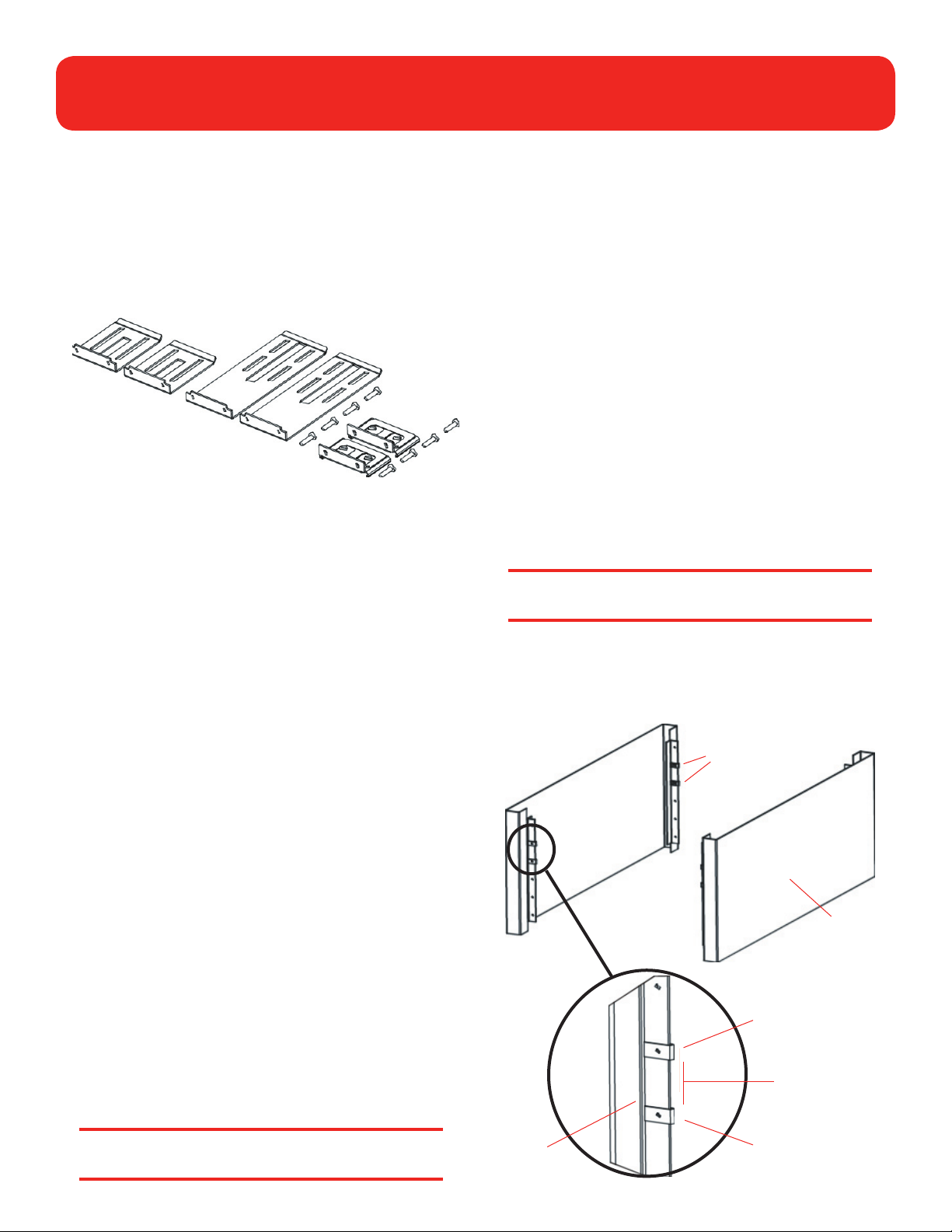
Step 2: Prepare Parts and Tools
a. Check that you have the following parts from the
SuperLoader accessories kit:
• 2 short SuperLoader brackets
• 2 long SuperLoader brackets
• 2 support brackets
• 8 10-32 x 1/4-inch button head support bracket screws
Short brackets
Long brackets
Support brackets
and screws
b. Obtain the following items from the accessories kit that
came with your rack:
• 8 clip nuts
• 8 screws
c. Make sure you have the following tools:
• #2 Phillips screwdriver
• Level
Step 3: Choose a Location for the
SuperLoader
The SuperLoader has the following dimensions:
• Length: 29.67 inches (753.7 mm)
• Width: 17.693 inches (449.4 mm)
• Height: 3.49 inches (88.6 mm)
Step 4: Install the SuperLoader in the
Rack
a. Take the following safety precautions for a rackmount
installation:
(1) Lower the rack’s feet.
(2) Extend the rack’s anti-tip device (if available).
(3) Ensure that the rack and all equipment mounted in the
rack have a reliable ground connection.
(4) Verify that the total current of the rack components
(including SuperLoader) will not exceed the current rating
of the power distribution unit or outlet receptacles. For
SuperLoader specifications, refer to the User’s Guide.
(5) Have the help of at least one other person. At least two
people are required to safely install the SuperLoader into
a rack.
Caution: Failure to take these safety precautions may
result in personal injury or equipment damage.
b. Install two clip nuts onto each of the four rails of the rack,
spacing the nuts 1.75 inches (44.45 mm) apart at exactly the
same level.
Clip nuts
The SuperLoader is designed to fit in a standard 19-inch rack
using either the long or short brackets (depending on the depth
of the rack).
When selecting a location for the SuperLoader, keep in mind the
following guidelines:
• Minimum clearances of 27 inches (686 mm) in front of
the unit and 17 inches (432 mm) in back are required to
facilitate component removal and installation.
• The SuperLoader should be positioned away from cooling
vents or exhaust from other devices to help minimize the
amount of debris entering the tape path.
Caution: Excessive dust or other debris in the tape
path can damage tapes and tape drives.
Rail
Rack
outer
cover
Clip nut
1.75 inches
(44.45 mm)
Clip nut
Page 3
SuperLoader
(SuperLoader DLT and SuperLoader LTO) Quick Start Guide
Page 3
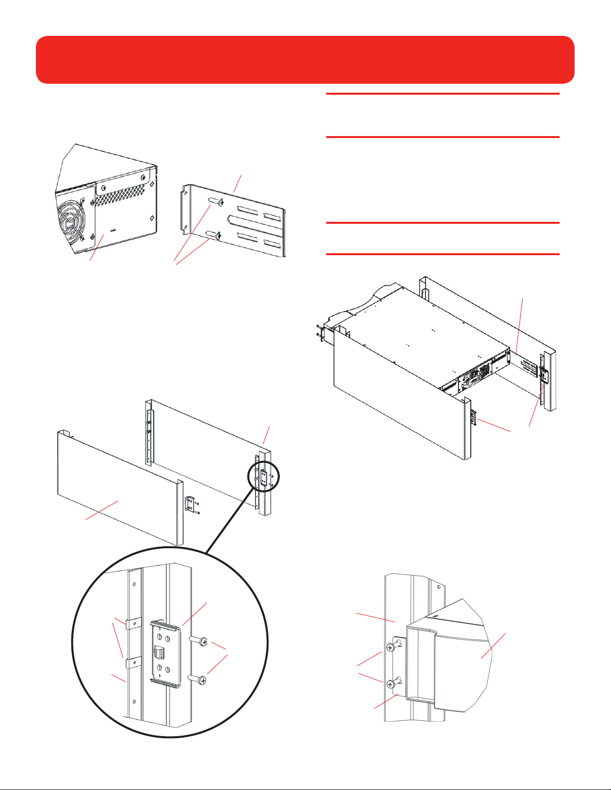
c. Select the long or short SuperLoader brackets (depending on
the depth of the rack) and attach them to the rear of the
SuperLoader on the right and left sides.
Bracket (right side)
Rear of
SuperLoader
Screws (10-32 x 1/4 only)
d. Using rack screws, attach a support bracket to the clip nuts
on each rear rail. Tighten the screws just enough to hold the
support brackets firmly against the rail while still allowing
the support bracket to be slightly shifted by hand. This
shifting will help facilitate the engagement of SuperLoader
brackets as the SuperLoader is installed in the rack (You will
fully tighten these screws later.)
Note: Be sure to attach the support brackets correctly;
the side of the bracket with only two holes should be
secured to the rail.
e. With the help of a second installer, insert the SuperLoader
into the rack so that each SuperLoader bracket slides into the
corresponding support bracket on the rear rails and the tabs
at the front of the SuperLoader align flush with the clip nuts
on the front rails.
Caution: Do not let go of the front end of the
SuperLoader until it can be secured to the rack.
SuperLoader
bracket
Rack
Clip nuts
Right
rear rail
Support
bracket
Rack
screws
Right
rear rail
Support
brackets
f. While the other installer holds the front end of the
SuperLoader, secure the SuperLoader in the rack by doing
the following:
(1) Secure the front end tabs of the SuperLoader to the
rack using four rack screws (two per tab). Make sure the
screws are finger tight.
Left
front
rail
Rack
screws
SuperLoader
(front)
Tab (one on
each side)
Page 4

SuperLoader
(SuperLoader DLT and SuperLoader LTO) Quick Start Guide
Page 4
(2) Install four screws (two per side) to secure the support
brackets to the SuperLoader brackets.
Superloader bracket
Support
bracket
Screws
SuperLoader (rear)
g. Verify that the SuperLoader is level. Make installation
adjustments as needed.
h. When the SuperLoader is level, tighten the screws securing
the SuperLoader tabs to the front rails, the SuperLoader
brackets to the support brackets, and the support brackets
to the rear rails.
Right
rear
rail
Power switch
Power
connector
SuperLoader (rear)
d. Attach the other end of the SCSI cable to the SCSI host
adapter card.
e. Complete the SCSI connection by doing one of the following:
• If the SuperLoader is the last device on the SCSI bus,
attach the SCSI terminator to the open port on the back
of the SuperLoader. Tighten the screws to secure the
terminator connection.
• If the SuperLoader is not the last device on the SCSI bus,
continue the SCSI bus using the open port on the back of
the SuperLoader.
Note: Do not turn on the host computer or any
devices connected to the host computer until you have
configured the SuperLoader and installed tape cartridges.
SCSI ports
Step 5: Establish the SCSI Connection
a. Make sure you have the supplied VHDCI SCSI cable and SCSI
terminator required for this part of the installation.
Note: If the host computer is connected to a network,
check with the system administrator before turning off
power.
b. Properly turn off all peripheral devices connected to the host
computer, and then turn off the host computer.
Caution: When installing SCSI cables, make sure you
correctly align all SCSI connectors to avoid bending
connector pins. Bent or damaged connector pins will
cause the SCSI connection to fail.
c. Attach the SCSI cable to either of the SCSI ports at the back
of the SuperLoader. Tighten the screws to secure the cable
connection.
Step 6: Turn on the SuperLoader
a. Connect the SuperLoader power cord as follows:
(1) Make sure the power switch at the back of the
SuperLoader is set to 0 (off).
(2) Connect the socket end of the power cord to the power
connector on the back of the SuperLoader.
(3) Connect the power cord plug to a grounded electrical
outlet.
b. Turn on the SuperLoader by setting the power switch at the
back of the SuperLoader to 1 (on).
The SuperLoader performs its power-on sequence, which
can be viewed on the LCD screen on the front panel of
the SuperLoader.
Page 5

SuperLoader
(SuperLoader DLT and SuperLoader LTO) Quick Start Guide
Page 5
Note: Do not turn on the host computer until after
you configure the SuperLoader (Step 7) and load tape
cartridges (Step 8).
c. If the SuperLoader LCD screen displays a warning message
any time during the power-up sequence, write down the
contents of the message and then press the Escape button
to clear the message.
Note: After completing this procedure (i.e., turning on
the SuperLoader for the first time), you should use the
power button on the front panel to turn the SuperLoader
on and off.
Step 7: Configure the SuperLoader
a. Determine/set the SCSI ID for the SuperLoader.
The SuperLoader is a SCSI device. Each SCSI device
attached to a server or workstation must have a unique
SCSI ID number. The SCSI IDs enable several devices to be
connected to a single computer without conflict.
The default SCSI ID for the SuperLoader is 5. You should
not have to change the default SCSI ID for SuperLoader
unless another SCSI device connected to the host
computer is already assigned the same ID number.
To change the SCSI ID for theSuperLoader, use the front
panel as explained in the User’s Guide.
b. Set the IP (Internet Protocol) address for the SuperLoader.
Step 8: Load Tape Cartridges
The SuperLoader can hold up to 16 tape cartridges in two
magazines, one installed on the left side and the other installed
on the right side of the SuperLoader. Cartridge slots in the left
magazine are numbered 1 to 8, and cartridge slots in the right
magazine are numbered 9 to 16.
The SuperLoader can also be shipped with an 8-cartridge
capacity. In this case, the SuperLoader comes with the left
magazine only; a magazine blank is installed on the right side.
Note: The SuperLoader will not run unless both
magazine openings are loaded with either a magazine or
magazine blank.
To load tape cartridges in the SuperLoader:
a. Eject and remove an empty magazine as follows:
(1) At the front panel of the SuperLoader, press Enter.
(2) Scroll to Commands and press Enter.
(3) Scroll to Eject and press Enter.
(4) If you are requested to enter a password, type 000000
(the default password) and press Enter.
(5) Scroll to Left Magazine (or Right Magazine as
appropriate) and press Enter to eject that magazine.
The selected magazine is released.
The SuperLoader is also an Ethernet device. Ethernet is
a method for accessing local networks as well as the
Internet. The Ethernet connection also enables you to
use the Web-based On-board Remote Manager to further
modify SuperLoader configuration.
All Ethernet devices must have a unique IP address.
In default configuration, the SuperLoader is assigned
a static IP address. This static IP address must be
modified to match the class of the local network, or the
SuperLoader must be reconfigured to accept dynamic IP
addresses.
For more information, refer to the User’s Guide.
Caution: To prevent damage to the SuperLoader or
to the magazine, both hands should be used when
removing the magazine from the SuperLoader.
(6) Grasp the magazine by the handle with one hand and
slide it out while supporting the length of the magazine
from underneath with the other hand. (See illustration
on following page.)
Note: When you eject a magazine, you must fully remove
it, or fully install it, before turning off the SuperLoader.
(7) To eject and remove the other magazine at this time,
press Escape, then scroll to the other magazine, and
press Enter. Then, repeat step 6.
To remove the other magazine later, repeat this
procedure.
Page 6

SuperLoader
(SuperLoader DLT and SuperLoader LTO) Quick Start Guide
SuperLoader
mounted in rack
Left magazine
Handle
c. Install the magazine(s) into the SuperLoader.
Page 6
Note: Each slot has a keying feature that prevents the
cartridge from being inserted incorrectly.
(4) Repeat this procedure until all tape cartridges have been
loaded into the magazine(s).
Note: You can remove a tape cartridge in the same
manner as you insert it. Use the dials on the magazine
to line up the desired tape cartridge with one of the
openings on the other side of the magazine. Then, using
your thumb and index finger, pull out the cartridge.
You will feel a little resistance as you begin to pull but
continue until the cartridge comes free.
Note: If a magazine blank is installed, it does not need to
be ejected. Instead, it can be installed/removed by sliding
it in/out using the handle.
b. Load tape cartridges into the magazine(s).
(1) Using the dials on the magazine, move the slot conveyor
belt within the magazine until a slot lines up with one of
the six openings on the other side of the magazine.
Right magazine (right side)
Dial
(2) Correctly orient the cartridge for insertion in the slot.
Right magazine (left side)
(1) Grasp the magazine by the handle with one hand and
support it from underneath with the other hand.
(2) Position the magazine correctly in the SuperLoader. The
magazine can only be inserted into the SuperLoader in
the correct orientation.
(3) Push the magazine in until it clicks and locks into place.
(4) Repeat this procedure to install a second magazine as
appropriate.
The SuperLoader performs an auto-inventory of the
tape cartridges in the magazine(s). Once completed, the
SuperLoader is ready for normal operation.
Dial
Note: These instructions are for both the SuperLoader
LTO and SuperLoader DLT due to the nature of
their similarities. Many component parts are not
interchangeable. These include the magazines, cartridges,
drive carrier assembly, magazine blank, magazine handle,
and the barcode scanner. Please order the appropriate
part numbers when replacing these items.
Openings
Tape cartridge
(note orientation)
Openings
(3) Insert the cartridge into the slot. As you push the
cartridge in, you will feel some resistance until the
cartridge latches into the slot.
Caution: When removing magazines or blanks, be
certain that no robotic operations are in process.
Failure to do so will stop the robot.
Page 7

SuperLoader
(SuperLoader DLT and SuperLoader LTO) Quick Start Guide
Page 7
Page 8

SuperLoader
(SuperLoader DLT and SuperLoader LTO) Quick Start Guide
Page 8
For more information,
visit our Web site
81-60222-15 A01
6707947-02cN 02
 Loading...