

Page 1

8OWULXP*HQHUDWLRQ
,QWHUQDO7DSH'ULYHV
*HWWLQJ6WDUWHG*XLGH
Page 2

Page 3

Contents
Read the “Pre-Installation” and “Installing the tape drive” sections if you have to install or
replace your Ultrium Generation 2 tape drive. If you have purchased your tape drive preinstalled in a server, go directly to the operating and troubleshooting information commencing
on page 23.
Pre-Installation
Before you start page 3
Backup software and drivers page 5
Installing the tape drive
Step 1: Check the SCSI connection page 7
Step 2: Check the drive’s SCSI ID page 9
Step 3: Prepare the mounting bay page 11
Step 4: Attach mounting hardware page 13
Step 5: Install the drive page 15
Step 6: Attach power and SCSI cables page 17
Step 7: Secure the drive page 19
Step 8: Verify installation page 21
Using the tape drive
Your Ultrium Generation 2 tape drive page 23
Use the correct media page 25
Optimizing performance page 27
Troubleshooting page 29
Understanding the LEDs page 33
Problems with cartridges page 36
11
Page 4

Copyright © 2003 by Hewlett-Packard Limited.
February 2003
This document was produced for your tape drive or library vendor by Hewlett-Packard.
The information contained in this document is subject to change without notice.
This document contains proprietary information which is protected by copyright. All rights are
reserved. No part of this document may be photocopied, reproduced or translated to another
language without the prior written consent of Hewlett-Packard Limited.
Hewlett-Packard shall not be liable for errors contained herein or for incidental or
consequential damages (including lost profits) in connection with the furnishing, performance,
or use of this material whether based on warranty, contract, or other legal theory.
Linear Tape-Open, LTO, LTO Logo, Ultrium and Ultrium Logo are U.S. trademarks of HP, IBM
and Seagate.
Patented under one or more of U.S. Patents Nos. 5,003,307; 5,016,009; 5,463,390;
5,506,580; held by Hi/fn, Inc.
Windows is a U.S. registered trademark of Microsoft Corp.
UNIX is a registered trademark of X/Open Company in the U.S. and other countries.
Product Details
Write your tape drive details here so you can find them easily if you need them. The model name is on the
front of the drive and the product and serial numbers are on a label on the top of the drive.
Model (type of drive):
Model (number):
Serial (number):
Date purchased/installed:
SCSI ID:
22
Page 5

Before you start
Ultrium Generation 2 tape drives are high performance Ultra 3 SCSI devices designed to
operate on a low voltage differential SCSI bus (LVDS). The tape drive is installed into a spare
drive bay in your server. To get optimum performance from your tape drive you need a SCSI
bus that can transfer data at a rate that supports the tape drive’s maximum burst transfer
speed of 160 MB/second. We recommend an Ultra 3 (160) or Ultra 4 (320) SCSI bus.
Before starting to install your tape drive, you should consider the following:
How do I connect the tape drive to my server’s SCSI bus?
Your tape drive is attached to the SCSI bus of the host server via a spare connection on the
internal SCSI ribbon cable. The cable must be terminated, see “Where should the SCSI
terminator be?” on page 17.
Server connection
You will need a properly installed and configured SCSI host bus adapter (HBA) or a built-in
SCSI controller on your server. For optimum performance your tape drive should only be
connected to an Ultra 3 (160) or Ultra 4 (320) host bus adapter or SCSI controller using a
correctly terminated, LVDS-compatible ribbon cable with a spare 68-pin, high density (HD),
wide SCSI connector. We recommend that the drive is the only device on the SCSI bus. Do not
attach the drive to the same SCSI bus as your disk drive or RAID controller.
See also Table 1, “supported SCSI bus types,” on page 7.
What are the mounting requirements for the tape drive?
Mounting bay
You need one industry standard, 5¼-inch, full-height bay in which to install the Ultrium
Generation 2 tape drive. Power requirements are:
Voltage Typical Current Maximum Current
5 V 3.2 A 6.3 A
12 V 0.7 A 2.75 A
Mounting hardware
For many servers, no mounting tray or rails are required. Devices simply slide into the
computer’s chassis and are fixed with screws. Other servers have built-in trays or rails.
Some servers require a special mounting tray or rails to fix the drive into the empty bay. If this
is the case with your system, you will have to order these accessories from the computer
manufacturer before you can install the tape drive. Mounting hardware for HP servers may be
ordered separately through your tape drive supplier. (Not all HP servers require rails. Some
have a built-in mounting tray.)
Airflow requirements
The server must provide forced cooling and be capable of drawing 6 cfm (0.17 m3/minute
or 10.08 m
3
/hour) of air through the tape drive.
33
Page 6

Ensure that all fans in your server are in place and operational, and make sure that empty
bays have the appropriate blanking plates installed so that airflow is maintained.
Do I need additional items for installation?
• If you do not have a spare, suitably rated SCSI connector on your server, a new HBA (also
known as a SCSI card) will be required. You will need to purchase and install the new HBA
into an unused, 64-bit PCI expansion slot within your server before installing your tape drive.
Full installation instructions and all necessary cables and mounting hardware are normally
provided with the HBA.
• You may also need mounting hardware. See “What are the mounting requirements for the
tape drive?” on page 3.
44
Page 7

Backup software and drivers
Backup software
For optimum performance it is important to use a backup application that is appropriate for
your system’s configuration. In a direct attach configuration, where the tape drive is attached
to a standalone server, you can use backup software that is designed for a single server
environment. In network configurations you will need backup software that supports enterprise
environments. HP, Veritas, Legato and Computer Associates all provide suitable products.
Further details about these products can be found on the software vendor’s web site.
Make sure you have a backup application that supports Ultrium Generation 2 tape drives and
download any upgrades or patches, if required.
Drivers
Windows users
Before you install the tape drive, download the driver from the manufacturer’s web site. Refer
to the accompanying README file for specific installation instructions for Windows NT and
Windows 2000/XP drivers. This will tell you whether you need to install the driver before or
after installing the tape drive.
UNIX users
The recommended backup applications use the operating system’s standard, built-in device
drivers. To upgrade drivers we recommend that you patch to the latest version of the operating
system or configure device files.
IA64 users
If you are installing on IA64, check the manufacturer’s web site for the latest information on
the availability of backup application upgrades and drivers.
55
Page 8
SCSI ribbon
cable
68-pin internal
LVD/SE connector
68-pin internal
SE connector
(Do not use)
50-pin internal SE
connector
(Do not use)
The example shows an
Adaptec 29160 HBA
tape drive
SCSI HBA
SCSI ribbon
cable
Figure 1: checking the SCSI connection
6
Page 9
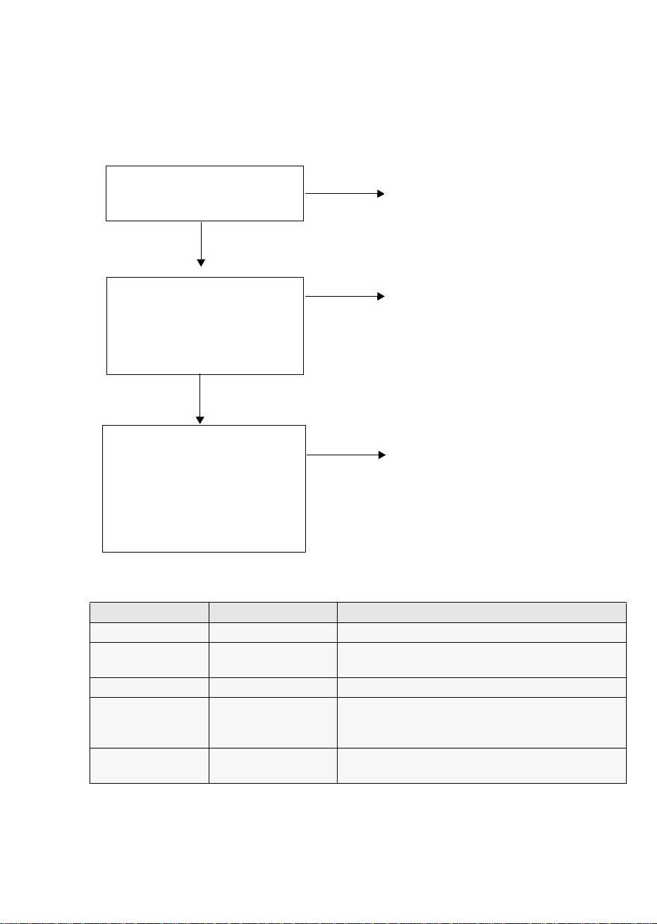
Step 1: Check the SCSI connection
Use the following questions to help you check your SCSI connection. If you answer ‘Yes’ to all
these questions, you are ready to install your tape drive. If you answer ‘No’, you will probably
need to purchase and install additional items.
Purchase and install one of the
1 Is there a spare SCSI port on
the server’s internal SCSI
bus?
Yes ?
No?
recommended HBAs into an unused
64-bit PCI expansion slot. (The HBA
can also be installed in a 32-bit PCI
expansion slot, but performance may
be degraded.)
2 Are the SCSI ribbon cable
and HBA card rated at Ultra
3 (160) or Ultra 4 (320)?
(Make sure the ribbon cable
is terminated. See page 19.)
Yes ?
3 Will the drive be the only
device on the bus? This is the
recommended configuration.
Do not connect to a RAID
controller channel. This is for
disk drives only.
SCSI Bus Type Transfer Speed Supported
Ultra 3 (160) LVD Up to 160 MB/s Yes. This is the recommended configuration.
Ultra 4 (320) LVD Up to 320 MB/s Yes. This is the recommended configuration for more
Ultra 2 LVD Up to 80 MB/s Yes, but this will not provide optimum performance.
Single-ended, wide Up to 40 MB/s Yes, but this is not recommended as it will severely
High Voltage
Differential
Up to 40 MB/s No. The drive will not work and you may damage
No?
No?
Performance may be impaired. See
table below.
Consider replacing
your card with one of the
recommended HBAs.
If you have a spare PCI slot, install a
new Ultra 160 HBA to provide a
dedicated SCSI bus. If you have to
configure more than one drive on the
same bus, install an Ultra 4 (320)
HBA.
than one drive per bus.
restrict performance.
Do not connect to a narrow SCSI bus.
the drive or controller
table 1: supported SCSI bus types
77
Page 10
Example SCSI IDs
(Default)
Figure 2: checking the SCSI ID
8
Page 11

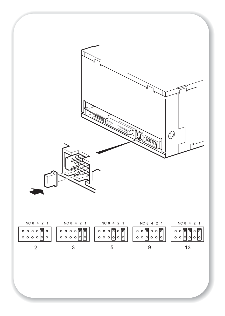
Step 2: Check the drive’s SCSI ID
Your Ultrium Generation 2 drive is shipped with a default SCSI ID of 3, but it can be
assigned any unused ID between 0 and 15. Do not use SCSI ID 7, which is reserved for the
SCSI controller, or SCSI ID 0, which is typically assigned to the boot disk.
1 Determine whether you need to change the SCSI ID from the default of 3.
Caution Static electricity can damage electronic components. Always wear an antistatic wriststrap if
possible. If not, to equalize the electromagnetic charges, touch a bare metal part of the
computer (such as the back plate) before you remove the tape drive from its bag.
2 Change the tape drive’s SCSI ID, if necessary.
The SCSI ID is set using jumpers on a set of pins at the rear of the drive. Move the jumpers
carefully to the pattern corresponding to the ID you want, see Figure 2.
99
Page 12
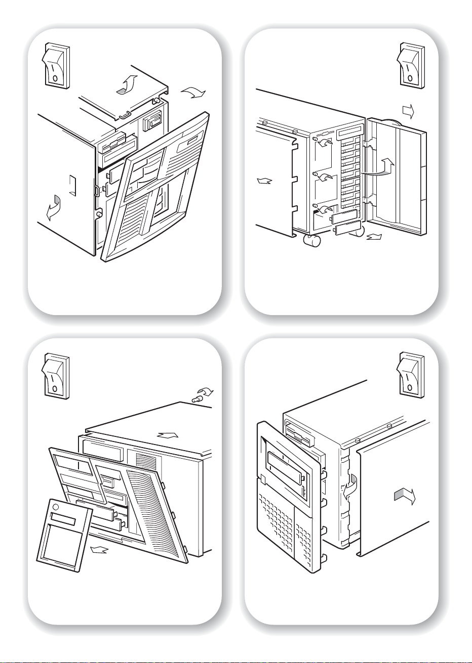
Figure 3a: preparing mounting bay in a
typical HP Netserver
Figure 3b: preparing mounting bay in a
typical HP Proliant server
Figure 3c: preparing mounting bay in a
typical IBM server
10
Figure 3d: preparing mounting bay in a
typical Dell server
Page 13

Step 3: Prepare the mounting bay
Warning To avoid personal injury or damage to the computer or tape drive, ensure that the
computer is disconnected from the mains power supply while you install the drive.
Caution Static electricity can damage electronic components. Always wear an antistatic wriststrap if
one is available. If not, after you have disconnected power from the computer and
removed the cover, touch a bare metal part of the chassis. Similarly, touch a bare metal
part of the drive before installing it.
1 Assemble the necessary tools and materials:
• Phillips screwdriver
• Flat-bladed screwdriver (if your computer uses slotted screws)
• Torx screwdriver (if your computer uses torx screws)
• Your computer manuals (for reference during installation)
2
Perform a normal system shutdown and turn off the computer and any connected
peripherals.
3 Remove the cover and front panel from the computer, as detailed in your computer’s
documentation.
As you work inside the computer, you may have to disconnect the SCSI cable or power
cable from other devices to maneuver the new drive into place. If you have to do this, make
a note of their position and connections so you can put them back correctly later.
4 Remove the front filler panel from a full-height, 5¼-inch bay of your computer, as illustrated.
Keep any screws for use in step 7 on page 19.
The server must provide forced cooling and be capable of drawing 6 cfm (0.17 m3/minute
or 10.08 m
appropriate blanking plates installed so that airflow is maintained.
3
/hour) of air through the tape drive. Ensure that empty bays have the
1111
Page 14

Figure 4a: attaching mounting tray
12
Figure 4b: attaching mounting rails
Page 15

Step 4: Attach mounting hardware
For many servers, no tray or rails are required. Devices simply slide into the computer’s
chassis and are fixed with screws. Other servers have built-in trays or rails.
If your computer does not require special mounting hardware, proceed to “Step 5: Install the
drive” on page 15 now.
If your computer requires special rails or other hardware to install the tape drive in the empty
bay, mount them on the tape drive in this step. Mounting hardware for HP servers may be
ordered separately through your tape drive supplier.
1 Attach the appropriate rails using the four screws supplied with the rail kit.
• If you are installing in a server that requires a tray, place the tape drive in the mounting tray
supplied, as shown in Figure 4a. The tray design may not necessarily be as shown.
• If you are installing in a server that requires mounting rails, fasten the rails to the tape drive,
as shown in Figure 4b. The rail design may not necessarily be as shown.
• Some servers have snap-on mounting rails attached to the filler panel. These can be removed
and attached to the tape drive with screws.
• If your computer uses other mounting hardware, attach it to the tape drive as directed in your
computer documentation.
Note The mounting hardware supplied may not be exactly the same as shown in the illustrations.
1313
Page 16

14
Figure 5: installing the drive
Page 17

Step 5: Install the drive
1 Slide the tape drive into the open bay, aligning the tray or rails with the slots in the bay, as
shown in Figure 5.
If your computer does not use mounting hardware, check that the holes in the chassis are
aligned with the holes in the side of the tape drive.
Do not secure the drive with screws at this point because you may have to move the drive to
get the cables into place.
1515
Page 18

2
SCSI ribbon
cable
2
SCSI ribbon
cable (correctly
terminated)
SCSI
controller
connection
1
power
cable
tape drive
1
power
cable
16
power
supply
Figure 6: attaching power and SCSI cables
Page 19

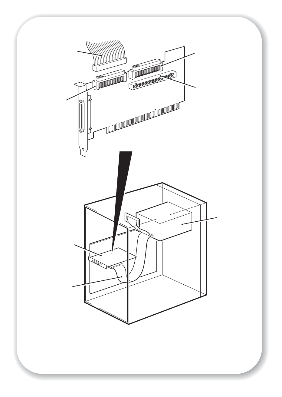
Step 6: Attach power and SCSI cables
1 Attach a spare power cable from the computer's internal power supply to the power
connector, as shown in Figure 6, item 1.
2 Attach a spare connector on the computer or HBA’s SCSI ribbon cable to the SCSI connector
of the drive, as shown in Figure 6, item 2.
3 If the drive is the last device on the SCSI chain, make sure that the SCSI cable is terminated
correctly.
Where should the SCSI terminator be?
Termination must be present at two and ONLY two positions on the SCSI bus—at the
beginning of the SCSI bus and at the end of the SCSI bus. Termination is normally enabled
by default on the HBA and most internal SCSI cables have a terminator attached. This will
usually be a small, rectangular block of plastic attached to the cable end and marked
‘SCSI Terminator’.
Therefore, assuming the HBA is the first device on the bus, you should check that the second
terminator is placed after the last device, as shown in Figure 6, item 2.
1717
Page 20

Figure 7a: securing drive to mounting hardware
18
Figure 7b: securing drive, no mounting hardware
Page 21

Step 7: Secure the drive
Mounting hardware used
1 Secure the tape drive into place. Use the screws you removed in “Step 3: Prepare the
mounting bay” on page 11 to fix the drive in place, as shown in Figure 7a.
2 Replace the cover on the computer.
No mounting hardware used
1 Secure the tape drive into place. Check that the holes in the chassis are aligned with the holes
in the sides of the drive and use the screws provided to secure the drive, as shown in Figure
7b.
2 Replace the cover on the computer.
1919
Page 22

arrow indicates leading
direction
affix label here
Figure 8a: loading a cartridge
20
Eject button
Figure 8b: unloading a cartridge
Page 23

Step 8: Verify installation
Once you have installed the drive hardware and ensured that you have downloaded any
upgrades and drivers necessary for your backup application (see page 5), verify that the tape
drive is functioning properly before you store your valuable data.
Check operation
1 Switch on the server. The tape drive will run its hardware self-test, which takes about 5
seconds. During the test the Ready LED flashes and all the other LEDs are off. On successful
completion the Ready LED is on. If the test fails the Drive Error and Tape Error LEDs flash, while
the Ready and Clean LEDs are off. This continues until the drive is reset. See “LEDs during selftest” on page 33 for more information.
2 Verify that the tape drive installation was successful.
If you encounter a problem during this verification procedure, turn to “Troubleshooting” on
page 29 for help in diagnosing and fixing the problem.
3 You are now ready to carry out a backup and restore test to check that the drive can write data
to tape. Use the blank cartridge supplied with the tape drive. See “Use the correct media” on
page 25 for more information about recommended cartridges.
To load a cartridge
1 Insert the cartridge into the slot in front of the drive with the white arrow uppermost and facing
the drive door. Apply gentle pressure until the drive takes the cartridge and loads it. (See
Figure 8a.)
2 The Ready light flashes green while the drive performs its load sequence. When the cartridge
is loaded, the Ready light shows steady green.
To perform a backup and restore test
Refer to your backup application documentation for specific instructions.
1 Perform a trial backup of data to tape.
2 Perform a trial restore of data from tape.
To unload a cartridge
Caution Never try to remove a cartridge before it is fully ejected or power off the tape drive while a
cartridge is still loaded.
1 Press the Eject button on the front panel. (See Figure 8b.)
2 The drive will complete its current task, rewind the tape to the beginning, and eject the
cartridge. The rewind process may take up to 15 minutes. The Ready light will flash to indicate
that the unload is still in progress.
2121
Page 24

Eject button
Status LEDs
Ready
Drive Error
Tape Error
Clean
Emergency
Reset
22
Figure 9: tape drive controls and indicators
Page 25

Your Ultrium Generation 2 tape drive
Your Ultrium Generation 2 tape drive has four LEDs (light emitting diodes) on the front panel,
which indicate drive status. These LEDs provide useful troubleshooting information. See also
“Understanding the LEDs” on page 33. See page 21 for more information about using the
eject button in normal operation and page 36 for details about force eject and emergency
reset.
Front panel LEDs
There are four LEDs as illustrated in the diagram. (See Figure 10.)
Ready (top, green)
• On: the drive is ready for use
• Off: the drive power is off or there was a failure during self-test
• Flashing: the drive is busy
Drive Error (second, amber)
• Off: no fault has been detected
• Flashing: the drive mechanism has detected a hardware error.
Tape Error (third, amber)
• Off: no fault has been detected
• Flashing: the tape currently in the drive is faulty. This LED could come on for a number of
reasons, but they all relate to the tape being in error in some way, such as unreadable
cartridge memory or unsupported tape. Do not use the cartridge; replace it. The LED will go
out when a tape load is started.
Clean (bottom, amber)
• On: cleaning cartridge in use
• Off: the drive does not require cleaning
• Flashing: the drive needs cleaning
2323
Page 26

24
padlock indicates
cartridge is protected
Figure 10: write-protecting cartridges
Page 27

Use the correct media
Data cartridges
Ultrium Generation 2 tape drives use Ultrium tape cartridges. These are single-reel cartridges
that match your drive's format and are optimized for high capacity, throughput and reliability.
Compatible media can be recognized by the Ultrium logo, which is the same as the logo on
the front of your drive. Do not use other format cartridges in your tape drive and do not use
Ultrium cartridges in other format tape drives.
We recommend Ultrium 400 GB tape cartridges for use with your tape drive (assuming 2:1
compression).
Write-protecting cartridges
If you want to protect the data on a cartridge from being altered or overwritten, you can writeprotect the cartridge.
Always remove the cartridge from the tape drive before you change the write protection.
• To write-protect a cartridge, slide the red tab by the label area on the rear face of the
cartridge to close the hole. Note the padlock on the tab that indicates that the cartridge is
protected.
• To write-enable a cartridge, slide the red tab back so that the hole is open before loading
it into the drive. Figure 10 illustrates the location of the write-protect tab.
Write-protection will not prevent a cartridge being erased by bulk-erasure or degaussing. Do
not bulk erase Ultrium format cartridges. This will destroy pre-recorded servo information and
make the cartridge unusable.
Cleaning cartridges
You must use Ultrium cleaning cartridges with Ultrium Generation 2 tape drives, as other
cleaning cartridges will not load and run. We recommend the Ultrium Universal cartridge.
Unlike some earlier Generation 1 Ultrium cleaning cartridges, the orange colored Ultrium
Universal cleaning cartridge is designed to work with any Ultrium compliant drive. Do not use
other format cartridges in your tape drive and do not use Ultrium cartridges in other format
tape drives.
To clean the tape drive:
A cleaning cartridge is supplied with each tape drive and should only be used when the
orange Clean LED is flashing.
1 Insert the cleaning cartridge.
2 The drive will carry out its cleaning cycle and eject the cartridge on completion (which can take
up to 5 minutes). During the cleaning cycle the orange Clean LED will be on solidly and the
green Ready LED will flash.
Each cleaning cartridge can be used up to 15 times. If the cleaning cartridge is ejected
immediately with the Tape Error LED on, it has expired.
2525
Page 28

Looking after cartridges
• Do not touch the tape media.
• Do not attempt to clean the tape path or tape guides inside the cartridge.
• Do not leave cartridges in excessively dry or humid conditions. Do not leave cartridges in
direct sunlight or in places where magnetic fields are present (for example, under
telephones, next to monitors or near transformers).
• Do not drop cartridges or handle them roughly.
• Stick labels onto the label area only.
• Do not bulk erase Ultrium format cartridges.
• See the insert included with the tape cartridge for storage conditions.
2626
Page 29

Optimizing performance
Various factors can affect tape drive performance, particularly in a network environment or if
the drive is not on a dedicated SCSI bus. If your tape drive is not performing as well as
expected, consider the following points.
Is the tape drive on a dedicated SCSI bus?
For optimum performance, we recommend that the tape drive is the only device on the SCSI
bus. If it is not, ensure other devices are LVD-compliant. If they are single-ended, the bus will
switch to single-ended mode with a lower transfer speed. There will also be restrictions on
cable length.
Can your system deliver the required performance?
The Ultrium Generation 2 tape drive can write data at 30 MB/s (native) or 60 MB/s
(compressed - assuming 2:1 compression), however, to get this performance it is essential that
your whole system can deliver this performance.
Typical areas where bottlenecks can occur are:
• Disk system (a single hard disk drive will not be able to deliver 60 MB/s transfer rates).
• Some file systems are able to transfer data faster than others.
• The type of data being backed up can affect backup performance (for example, file sizes
and compressibility).
• Some backup software performs better than others.
To improve performance you may like to consider a RAIDed disk solution with a large number
of physical hard disks.
Some enterprise class backup applications can be made to interleave data from multiple
sources, such as clients or disks, to keep the tape drive working at optimum performance.
Is the data transfer rate too slow?
Adaptive Tape Speed (ATS) enables the drive to “stream” data at variable tape speed, which
means that it maintains a continuous data flow to tape even when the transfer speed varies.
This is automatically managed by the drive to keep the drive running at best performance.
When using Ultrium 2 cartridges, the ATS range is 10 -30 MB/s, so, if possible data transfer
should remain within this range. In most cases, the backup application will provide details of
the average time taken at the end of the backup.
For optimum performance always use Ultrium 2 cartridges. If you are using Ultrium 1
cartridges, the ATS range is 6.6-20 MB/s.
2727
Page 30

Performance checklist
The following list summarizes factors that can affect performance. They provide a guideline
only of areas that may need further investigation. They do not attempt to explain how to
configure individual systems.)
• Is the tape drive reading and writing data at the correct speed?
• Is the source system (hard disk) transferring data at the correct speed?
• Is the backup application writing buffers at the correct speed? You may need to tune the
transfer, buffer and block size settings to optimize the speed that the application writes data
to the tape drive. Ultrium Generation 2 tape drives have an internal buffer of 64 MB.
• Is the operating system tuned for performance? You may need to adjust the data transfer
packet size.
• Are user applications, such as Exchange or database servers, optimized for backup
performance?
• Are there other factors that could be affecting performance, such as interference or fibre
channel infrastructure?
2828
Page 31

Troubleshooting
The first step in problem-solving is establishing whether the problem lies with the cartridge, the
drive, the host computer and its connections, or with the way the system is being operated.
Most modern SCSI host bus adapters locate and display attached devices when the system is
booting up. On Windows systems, if you swap or connect a product when your system is
running, you will need to reboot the system. IA32 systems also usually need to be rebooted.
UNIX systems may have pluggable drivers, which allow drives to be attached to a running
system and detected without rebooting.
If the device is not detected on boot up, there is probably a problem with the physical
hardware: cables, termination, connections, power or the host bus adapter itself. If the device
is displayed during boot up but cannot be found in the operating system, this is more likely to
be a software problem.
• If you encounter a problem during installation and need further clarification, refer to the
“Problems encountered during installation” on page 30.
• If a problem arises during testing after you have installed the drive, refer to the symptombased section “Testing after installation” on page 31.
• For more information about LED sequences, refer to “Understanding the LEDs” on page 33.
• For information about cartridges, refer to “Problems with cartridges” on page 36.
2929
Page 32

Problems encountered during installation
Unpacking
Description Further information
Some parts appear to be missing or
damaged.
The server requires mounting hardware
Description Further information
Additional parts may be required for
fitting the tape drive into the server.
Does the SCSI ID need changing?
Description Further information
SCSI ID 3 is already in use. The Ultrium Generation 2 internal drive has its
How should the SCSI bus be terminated?
Contact your vendor if any parts need replacing.
Mounting hardware may need to be ordered
separately through your tape drive vendor or
computer manufacturer.
SCSI ID set to 3 by default. This should be left
unchanged unless this number is already in use.
Full instructions on how to change the SCSI ID are
given on page 9.
Description Further information
It is unclear if the bus is already
terminated or where an additional
terminator should be placed.
Both ends of a SCSI bus must be terminated.
Typically, when connecting an internal drive to the
ribbon cable already inside your server then both
the host bus adapter and the end of the ribbon
cable will already be terminated and no further
action is required.
3030
Page 33

Is the correct SCSI host bus adapter installed?
Description Further information
The server already has a SCSI host bus
adapter but it is difficult to determine
what type it is.
The server may not have a SCSI host bus
adapter installed.
You can check the SCSI configuration from the
boot-up screen or from the Windows Control
Panel.
If not, you will need to purchase one. See
“supported SCSI bus types” on page 7.
Do drivers need to be installed and, if so, which one?s
Description Further information
It is unclear whether there is a need to
install drivers onto the system and more
help is required.
For detailed information specific to your system
check the software vendor’s web site.
(Backup software that states support for Ultrium
Generation 2 tape drives also provides the
required drivers.)
Testing after installation
Remember that the system recognizes devices during boot-up. If you swap or connect a
product when your system is running, you will need to reboot the system. Rebooting the system
will reset devices and will often resolve problems. It is good practice to reboot every time you
add a driver or install firmware.
Caution Never power off the drive while a cartridge is still loaded or during a firmware upgrade.
The computer does not reboot after installation
Possible reason Recommended action
You have installed an additional SCSI
host bus adapter and its resources are
clashing with an existing adapter.
You have disconnected the power or SCSI
cable from the computer’s boot disk
during the drive installation process.
Remove the new host bus adapter and check the
server documentation.
Check that the cables to all devices are firmly
connected.
3131
Page 34

The computer boots but does not recognize the tape drive
Possible reason Recommended action
The power or SCSI cable is not connected
properly.
The SCSI bus is not terminated correctly. Check that the SCSI bus is actively terminated.
The tape drive’s SCSI ID address is not
unique.
Check that the cables to the tape drive are firmly
connected. Ensure that the SCSI cable is LVDScompliant and does not have any bent pins.
Replace, if necessary.
(Refer also to the documentation for your SCSI
controller and any other SCSI devices you may
have.)
Make sure that each device on the SCSI bus has a
unique ID.
We recommend that the tape drive is connected
to a dedicated host bus adapter. Do not connect
the drive to a disk RAID controller as this is not
supported.
The application does not recognize the tape drive
Possible reason Recommended action
The application does not support the tape
drive.
Some applications require drivers to be
loaded.
Check that the drive is installed properly. Refer to
the software vendor’s World Wide Web site and
load any service packs as necessary.
Check that the correct SCSI and tape drive drivers
are installed. Consult the backup application’s
installation notes for details.
3232
The drive does not work
Possible reason Recommended action
If the drive does not power up (all LEDs
are off), the power cable may not be
connected to the drive properly.
If the self-test fails (see “LEDs during selftest” on page 33), there may be a
hardware or firmware failure.
Check the power cable connection and try
another cable if necessary. If the drive still does
not power up, call for assistance.
If there is a cartridge in the drive, remove it.
Power down the drive and power it up again. Try
another power connector. If the power supply is
present and all LEDs remain off, try the reset
button to power cycle the drive. If the self-test still
fails, call for assistance.
Page 35

Understanding the LEDs
LEDs during self-test
Your Ultrium Generation 2 tape drive has four LEDs (light emitting
diodes) on the front panel, which indicate drive status. These LEDs
provide useful troubleshooting information.
The tape drive performs a power on self-test whenever power is applied
or the drive is reset. The test takes about 5 seconds.
The green Ready light flashes several times and then remains on if selftest passes. All other LEDs remain off.
If the self-test fails, the Drive Error and Tape Error LEDs flash, while the
Ready and Clean LEDs are off. This continues until the drive is reset.
Using the LEDs for troubleshooting
Use the following table to interpret the front panel LED sequences and the appropriate action
to take, if any.
LED
Sequence
Cause Action required
All LEDs OFF.
Drive may not have
power, may be faulty or
may have been power
cycled or reset during a
firmware upgrade.
Ready and Clean OFF.
Drive Error and Tape Error
FLASHING
The drive has failed to
execute power-on self
test (POST).
Ready is ON.
The drive is ready for
operation.
.
Make sure the server is switched on.
If this is not on, check the internal power cable con-
nection and replace the cable if necessary.
If the power supply is present and all LEDs remain off,
press emergency reset (see page 23) or power cycle
the server. If it still fails, call for service.
Power cycle or reset the server.
If the error condition reappears, call for service.
None. This is normal.
3333
Page 36

LED
Sequence
Cause Action required
Ready is FLASHING.
The drive is carrying out
a normal activity (read,
None.
If the drive is upgrading firmware, do not reset or
power cycle it.
write).
Ready is FLASHING fast.
The drive is
downloading firmware.
Ready is OFF, others are
ON.
Firmware is being
reprogrammed.
Clean is FLASHING.
The drive requires
cleaning.
Ready is FLASHING and
Clean is ON.
Cleaning is in progress.
None.
Do not reset or power cycle the drive.
None.
Do not reset or power cycle the drive.
Load the Ultrium cleaning cartridge. See page 25 for
supported cartridges and instructions.
If the clean LED is still flashing when you load a new
or known data cartridge after cleaning, call for
service.
None. The cleaning cartridge will eject on completion.
The cleaning cycle can take up to 5 minutes to
complete.
3434
Tape Error is FLASHING.
The drive believes the
current tape or the tape
just ejected is faulty.
Unload the tape cartridge. Make sure that you are
using the correct format cartridge; an Ultrium data
cartridge or Ultrium Universal cleaning cartridge. (See
page 25.)
Reload the cartridge. If the 'Tape Error' LED still
flashes or starts flashing during the next backup, load
a new or known, good cartridge.
If the 'Tape Error' LED is now off, discard the 'suspect'
tape cartridge. If it is still on, call for service.
The tape is ejected
immediately and Tape
or
Error is FLASHING, or
Drive Error FLASHES on
unloading tape.
Write-protect the cartridge by sliding the red switch on
the tape cartridge. The tape can be loaded and the
data read. Once the data is recovered, the cartridge
must be discarded.
The tape cartridge
memory (CM) may be
faulty.
Page 37

LED
Sequence
Cause Action required
Drive Error FLASHING.
The drive mechanism
has detected an error.
Load a new cartridge. If the error persists, power cycle
or reset the drive.
If the 'Drive Error' LED remains on, call for service.
then
Drive Error, Tape Error and
Ready FLASHING.
There is a firmware
download problem.
Drive Error and Ready ON
with Tape Error and Clean
OFF. Sequence alternates
repeatedly.
The drive has a
firmware error.
Insert a cartridge to clear the LED sequence. If the
condition persists, call for service.
Power cycle or reset the drive.
Upgrade the firmware. If the condition persists, call for
service.
3535
Page 38

Problems with cartridges
If you experience any problems using Ultrium branded cartridges, check:
• The cartridge case is intact and that it contains no splits, cracks or damage.
• The cartridge has been stored at the correct temperature and humidity. This prevents
condensation. See the insert included with the tape cartridge for storage conditions.
• The write-protect switch is fully operational. It should move from side to side with a positive
click.
Cartridge is jammed
If the cartridge is jammed or the backup application is unable to eject it, you can force eject
the cartridge. Once the cartridge is successfully ejected, it is good practise to upgrade the
firmware.
1 Press and hold the Eject button on the front of the tape drive for 10 seconds.
2 Wait for the cartridge to be ejected. This process may take up to 15 minutes (the maximum
rewind time). It is important that you allow sufficient time for the drive to complete this process.
If you interrupt it, you may damage the media or the tape drive.
3 If the cartridge is still jammed, press the emergency reset button as shown on page 22. (Use
the tip of a paperclip to press the button.)
4 Wait for the drive to reset and get back to the loaded position. This process may take up to 15
minutes (the maximum rewind time) to complete.
5 Press and hold the Eject button for 10 seconds.
If the cartridge is still jammed, the tape drive has failed.
The drive will not accept cartridge (or ejects it immediately)
The cartridge may have been damaged, for example dropped, the cartridge memory may be
corrupted or the drive may have a fault.
1 Check that the drive has power (the power cable is properly connected and the ready LED is
on).
2 Check that you are using the correct media. Only use Ultrium media, we recommend Ultrium
2 cartridges (see page 25).
3 Make sure that you have loaded the cartridge with the correct orientation (see “To load a
cartridge” on page 21.)
3636
Page 39

4 Check for damage to your media (to the cartridge case, leader pin or cartridge teeth) and
discard it if it is damaged.
5 Use a new or known, good piece of media and see if it loads. If it does, the original cartridge
is faulty and should be discarded.
6 Check if another Ultrium Generation 2 drive will accept the cartridge. If it does, the original
drive may be faulty. Before calling customer service, please check that the tape drive is
responding and that it can be seen on the SCSI bus.
3737
Page 40

3838
 Loading...