

Page 1

HP LTO Ultrium tape drives
technical reference manual
LTO4 FC, SCSI and SAS drives
volume 1: hardware integration
Edition 1, June 2007
HP restricted
Page 2

Legal and notice information
© Copyright 2005–2007 Hewlett-Packard Development Company, L.P.
Hewlett-Packard Company makes no warranty of any kind with regard to this material, including, but not limited to, the implied
warranties of merchantability and fitness for a particular purpose. Hewlett-Packard shall not be liable for errors contained herein or
for incidental or consequential damages in connection with the furnishing, performance, or use of this material.
This document contains proprietary information, which is protected by copyright. No part of this document may be photocopied,
reproduced, or translated into another language without the prior written consent of Hewlett-Packard. The information is provided
“as is” without warranty of any kind and is subject to change without notice. The only warranties for HP products and services are
set forth in the express warranty statements accompanying such products and services. Nothing herein should be construed as
constituting an additional warranty. HP shall not be liable for technical or editorial errors or omissions contained herein.
Revision history
Version Edition Date Changes
LTO 4 Edition 1 June 2007 LTO4 drives
This document is frequently revised and updated. To find out if there is a later version, please ask your HP OEM Representative.
HP LTO Ultrium 4 drives technical reference manual, volume 1: hardware integration
HP restricted
Page 3

Contents
Related documents . . . . . . . . . . . . . . . . . . . . . . . . . . . . . . . . . . . . . . . . . . . . . . . . . . . . . . . . . 9
Related documents . . . . . . . . . . . . . . . . . . . . . . . . . . . . . . . . . . . . . . . . . . . . . . . . . . . . . . . . . 9
Documentation map. . . . . . . . . . . . . . . . . . . . . . . . . . . . . . . . . . . . . . . . . . . . . . . . . . . . . . 9
Drives—general . . . . . . . . . . . . . . . . . . . . . . . . . . . . . . . . . . . . . . . . . . . . . . . . . . . . . . 9
Installation and configuration . . . . . . . . . . . . . . . . . . . . . . . . . . . . . . . . . . . . . . . . . . . . . 9
Operation . . . . . . . . . . . . . . . . . . . . . . . . . . . . . . . . . . . . . . . . . . . . . . . . . . . . . . . . . 10
Cartridges . . . . . . . . . . . . . . . . . . . . . . . . . . . . . . . . . . . . . . . . . . . . . . . . . . . . . . . . . 10
Interface . . . . . . . . . . . . . . . . . . . . . . . . . . . . . . . . . . . . . . . . . . . . . . . . . . . . . . . . . . 10
Maintenance and troubleshooting . . . . . . . . . . . . . . . . . . . . . . . . . . . . . . . . . . . . . . . . . 11
Dealing with errors . . . . . . . . . . . . . . . . . . . . . . . . . . . . . . . . . . . . . . . . . . . . . . . . . . . 11
LTO Ultrium features . . . . . . . . . . . . . . . . . . . . . . . . . . . . . . . . . . . . . . . . . . . . . . . . . . 11
General documents and standardization . . . . . . . . . . . . . . . . . . . . . . . . . . . . . . . . . . . . . . 12
1 LTO Ultrium drives in libraries . . . . . . . . . . . . . . . . . . . . . . . . . . . . . . . . . . . . . 13
Introduction . . . . . . . . . . . . . . . . . . . . . . . . . . . . . . . . . . . . . . . . . . . . . . . . . . . . . . . . . . . . . 13
Backup software . . . . . . . . . . . . . . . . . . . . . . . . . . . . . . . . . . . . . . . . . . . . . . . . . . . . . . . 13
Front panel for automation use . . . . . . . . . . . . . . . . . . . . . . . . . . . . . . . . . . . . . . . . . . . . . . . . 14
Front panel for use in autoloaders . . . . . . . . . . . . . . . . . . . . . . . . . . . . . . . . . . . . . . . . . . . 14
Installing drives . . . . . . . . . . . . . . . . . . . . . . . . . . . . . . . . . . . . . . . . . . . . . . . . . . . . . . . . . . 16
Airflow requirements . . . . . . . . . . . . . . . . . . . . . . . . . . . . . . . . . . . . . . . . . . . . . . . . . . . . 16
Measuring internal drive temperatures. . . . . . . . . . . . . . . . . . . . . . . . . . . . . . . . . . . . . . 16
Electrical fit . . . . . . . . . . . . . . . . . . . . . . . . . . . . . . . . . . . . . . . . . . . . . . . . . . . . . . . . . . . 18
Rear panel and connectors . . . . . . . . . . . . . . . . . . . . . . . . . . . . . . . . . . . . . . . . . . . . . . . . 18
Fixing dimensions . . . . . . . . . . . . . . . . . . . . . . . . . . . . . . . . . . . . . . . . . . . . . . . . . . . . . . 19
Bottom panel . . . . . . . . . . . . . . . . . . . . . . . . . . . . . . . . . . . . . . . . . . . . . . . . . . . . . . . 20
Side panel . . . . . . . . . . . . . . . . . . . . . . . . . . . . . . . . . . . . . . . . . . . . . . . . . . . . . . . . . 20
Operating drives . . . . . . . . . . . . . . . . . . . . . . . . . . . . . . . . . . . . . . . . . . . . . . . . . . . . . . . . . 20
Cleaning . . . . . . . . . . . . . . . . . . . . . . . . . . . . . . . . . . . . . . . . . . . . . . . . . . . . . . . . . . . . 21
Resetting drives . . . . . . . . . . . . . . . . . . . . . . . . . . . . . . . . . . . . . . . . . . . . . . . . . . . . . . . . 21
Troubleshooting . . . . . . . . . . . . . . . . . . . . . . . . . . . . . . . . . . . . . . . . . . . . . . . . . . . . . . . . . . 22
Diagnostics . . . . . . . . . . . . . . . . . . . . . . . . . . . . . . . . . . . . . . . . . . . . . . . . . . . . . . . . . . . 22
Forced eject . . . . . . . . . . . . . . . . . . . . . . . . . . . . . . . . . . . . . . . . . . . . . . . . . . . . . . . . . . 22
Cleaning issues . . . . . . . . . . . . . . . . . . . . . . . . . . . . . . . . . . . . . . . . . . . . . . . . . . . . . . . . 23
2 Using special features in libraries . . . . . . . . . . . . . . . . . . . . . . . . . . . . . . . . . . 25
Introduction . . . . . . . . . . . . . . . . . . . . . . . . . . . . . . . . . . . . . . . . . . . . . . . . . . . . . . . . . . . . . 25
Automation and drive interface . . . . . . . . . . . . . . . . . . . . . . . . . . . . . . . . . . . . . . . . . . . . . . . 25
Automation Control Interface (ACI) . . . . . . . . . . . . . . . . . . . . . . . . . . . . . . . . . . . . . . . . . . 25
Automation/Drive Interface (ADI). . . . . . . . . . . . . . . . . . . . . . . . . . . . . . . . . . . . . . . . . . . . 26
Configuring autoload and library-controlled loads . . . . . . . . . . . . . . . . . . . . . . . . . . . . . . . . . . 27
Cartridge positions during load and unload . . . . . . . . . . . . . . . . . . . . . . . . . . . . . . . . . . . . 27
HP LTO Ultrium 4 drives technical reference manual, volume 1: hardware integration 3
HP restricted
Page 4

Load scenarios . . . . . . . . . . . . . . . . . . . . . . . . . . . . . . . . . . . . . . . . . . . . . . . . . . . . . . . . 28
Load forces . . . . . . . . . . . . . . . . . . . . . . . . . . . . . . . . . . . . . . . . . . . . . . . . . . . . . . . . . . . 29
Using Cartridge Memory (LTO-CM). . . . . . . . . . . . . . . . . . . . . . . . . . . . . . . . . . . . . . . . . . . . . 30
Use in libraries . . . . . . . . . . . . . . . . . . . . . . . . . . . . . . . . . . . . . . . . . . . . . . . . . . . . . . . . 31
Current libraries — barcodes . . . . . . . . . . . . . . . . . . . . . . . . . . . . . . . . . . . . . . . . . . . . 31
More information. . . . . . . . . . . . . . . . . . . . . . . . . . . . . . . . . . . . . . . . . . . . . . . . . . . . . . . 32
3 Drives in tape arrays . . . . . . . . . . . . . . . . . . . . . . . . . . . . . . . . . . . . . . . . . . . 33
Installing drives . . . . . . . . . . . . . . . . . . . . . . . . . . . . . . . . . . . . . . . . . . . . . . . . . . . . . . . . . . 33
Identifying the drive . . . . . . . . . . . . . . . . . . . . . . . . . . . . . . . . . . . . . . . . . . . . . . . . . . . . . 33
Modes of usage . . . . . . . . . . . . . . . . . . . . . . . . . . . . . . . . . . . . . . . . . . . . . . . . . . . . . . . 33
Attaching to Fibre Channel . . . . . . . . . . . . . . . . . . . . . . . . . . . . . . . . . . . . . . . . . . . . . . . . 33
Attaching to SCSI . . . . . . . . . . . . . . . . . . . . . . . . . . . . . . . . . . . . . . . . . . . . . . . . . . . . . . 33
Attaching to SAS . . . . . . . . . . . . . . . . . . . . . . . . . . . . . . . . . . . . . . . . . . . . . . . . . . . . . . . 33
Appropriate HP rack-mount systems. . . . . . . . . . . . . . . . . . . . . . . . . . . . . . . . . . . . . . . . 33
Airflow requirements . . . . . . . . . . . . . . . . . . . . . . . . . . . . . . . . . . . . . . . . . . . . . . . . . . 33
Setting the SCSI ID. . . . . . . . . . . . . . . . . . . . . . . . . . . . . . . . . . . . . . . . . . . . . . . . . . . . . . 34
Termination . . . . . . . . . . . . . . . . . . . . . . . . . . . . . . . . . . . . . . . . . . . . . . . . . . . . . . . . 34
Inserting a drive . . . . . . . . . . . . . . . . . . . . . . . . . . . . . . . . . . . . . . . . . . . . . . . . . . . . . . . 35
Connecting to a Fibre Channel router or by SCSI/SAS to a server or router . . . . . . . . . . . . . . 35
Fibre Channel connection . . . . . . . . . . . . . . . . . . . . . . . . . . . . . . . . . . . . . . . . . . . . . . 35
Server SCSI connection . . . . . . . . . . . . . . . . . . . . . . . . . . . . . . . . . . . . . . . . . . . . . . . . 35
Server SAS connection . . . . . . . . . . . . . . . . . . . . . . . . . . . . . . . . . . . . . . . . . . . . . . . . 36
Replacing a drive . . . . . . . . . . . . . . . . . . . . . . . . . . . . . . . . . . . . . . . . . . . . . . . . . . . . . . . . . 36
Removing a drive . . . . . . . . . . . . . . . . . . . . . . . . . . . . . . . . . . . . . . . . . . . . . . . . . . . . . . 36
Installing a new drive . . . . . . . . . . . . . . . . . . . . . . . . . . . . . . . . . . . . . . . . . . . . . . . . . . . . 36
Operating the drive . . . . . . . . . . . . . . . . . . . . . . . . . . . . . . . . . . . . . . . . . . . . . . . . . . . . . . . 36
Front panel features . . . . . . . . . . . . . . . . . . . . . . . . . . . . . . . . . . . . . . . . . . . . . . . . . . . . . 37
LEDs . . . . . . . . . . . . . . . . . . . . . . . . . . . . . . . . . . . . . . . . . . . . . . . . . . . . . . . . . . . . . 37
Reset switch . . . . . . . . . . . . . . . . . . . . . . . . . . . . . . . . . . . . . . . . . . . . . . . . . . . . . . . . 38
Loading a cartridge . . . . . . . . . . . . . . . . . . . . . . . . . . . . . . . . . . . . . . . . . . . . . . . . . . . . . 38
Unloading a cartridge . . . . . . . . . . . . . . . . . . . . . . . . . . . . . . . . . . . . . . . . . . . . . . . . . . . 38
Cleaning the drive . . . . . . . . . . . . . . . . . . . . . . . . . . . . . . . . . . . . . . . . . . . . . . . . . . . . . . . . 39
Troubleshooting . . . . . . . . . . . . . . . . . . . . . . . . . . . . . . . . . . . . . . . . . . . . . . . . . . . . . . . . . . 39
Emergency unload . . . . . . . . . . . . . . . . . . . . . . . . . . . . . . . . . . . . . . . . . . . . . . . . . . . . . . 39
General guidelines . . . . . . . . . . . . . . . . . . . . . . . . . . . . . . . . . . . . . . . . . . . . . . . . . . . . . 39
Problems with the host computer . . . . . . . . . . . . . . . . . . . . . . . . . . . . . . . . . . . . . . . . . . 40
Problems with the drive and cartridge . . . . . . . . . . . . . . . . . . . . . . . . . . . . . . . . . . . . . . 41
4 Internal drives in servers. . . . . . . . . . . . . . . . . . . . . . . . . . . . . . . . . . . . . . . . . 45
Installing an internal drive into a server . . . . . . . . . . . . . . . . . . . . . . . . . . . . . . . . . . . . . . . . . . 45
Identifying the model . . . . . . . . . . . . . . . . . . . . . . . . . . . . . . . . . . . . . . . . . . . . . . . . . . . . 45
Standards and safety . . . . . . . . . . . . . . . . . . . . . . . . . . . . . . . . . . . . . . . . . . . . . . . . . . . . 45
Requirements . . . . . . . . . . . . . . . . . . . . . . . . . . . . . . . . . . . . . . . . . . . . . . . . . . . . . . . . . 45
Mounting requirements . . . . . . . . . . . . . . . . . . . . . . . . . . . . . . . . . . . . . . . . . . . . . . . . 45
Airflow and cooling . . . . . . . . . . . . . . . . . . . . . . . . . . . . . . . . . . . . . . . . . . . . . . . . . . 45
Power requirements. . . . . . . . . . . . . . . . . . . . . . . . . . . . . . . . . . . . . . . . . . . . . . . . . . . 46
4
HP restricted
Page 5

Server connections . . . . . . . . . . . . . . . . . . . . . . . . . . . . . . . . . . . . . . . . . . . . . . . . . . . 47
Fixing dimensions. . . . . . . . . . . . . . . . . . . . . . . . . . . . . . . . . . . . . . . . . . . . . . . . . . . . . . . . . 48
Bottom panel, full-height internal drives . . . . . . . . . . . . . . . . . . . . . . . . . . . . . . . . . . . . . 49
Side panel, full-height internal drives . . . . . . . . . . . . . . . . . . . . . . . . . . . . . . . . . . . . . . . 49
Connecting the drive. . . . . . . . . . . . . . . . . . . . . . . . . . . . . . . . . . . . . . . . . . . . . . . . . . . . . . . 49
Fibre Channel connector. . . . . . . . . . . . . . . . . . . . . . . . . . . . . . . . . . . . . . . . . . . . . . . . . . 49
SCSI connector . . . . . . . . . . . . . . . . . . . . . . . . . . . . . . . . . . . . . . . . . . . . . . . . . . . . . . . . 50
Termination . . . . . . . . . . . . . . . . . . . . . . . . . . . . . . . . . . . . . . . . . . . . . . . . . . . . . . . . 51
SAS connector . . . . . . . . . . . . . . . . . . . . . . . . . . . . . . . . . . . . . . . . . . . . . . . . . . . . . . . . 51
Backup software. . . . . . . . . . . . . . . . . . . . . . . . . . . . . . . . . . . . . . . . . . . . . . . . . . . . . . . . . . 51
Operating the drive . . . . . . . . . . . . . . . . . . . . . . . . . . . . . . . . . . . . . . . . . . . . . . . . . . . . . . . 52
Front panel features . . . . . . . . . . . . . . . . . . . . . . . . . . . . . . . . . . . . . . . . . . . . . . . . . . . . . 53
LEDs . . . . . . . . . . . . . . . . . . . . . . . . . . . . . . . . . . . . . . . . . . . . . . . . . . . . . . . . . . . . . 53
Reset switch . . . . . . . . . . . . . . . . . . . . . . . . . . . . . . . . . . . . . . . . . . . . . . . . . . . . . . . . 53
Loading a cartridge . . . . . . . . . . . . . . . . . . . . . . . . . . . . . . . . . . . . . . . . . . . . . . . . . . . . . 54
Unloading a cartridge . . . . . . . . . . . . . . . . . . . . . . . . . . . . . . . . . . . . . . . . . . . . . . . . . . . 54
Cleaning the drive . . . . . . . . . . . . . . . . . . . . . . . . . . . . . . . . . . . . . . . . . . . . . . . . . . . . . . . . 54
Troubleshooting . . . . . . . . . . . . . . . . . . . . . . . . . . . . . . . . . . . . . . . . . . . . . . . . . . . . . . . . . . 55
Emergency unload . . . . . . . . . . . . . . . . . . . . . . . . . . . . . . . . . . . . . . . . . . . . . . . . . . . . . . 55
General guidelines . . . . . . . . . . . . . . . . . . . . . . . . . . . . . . . . . . . . . . . . . . . . . . . . . . . . . 55
Diagnosing the problem . . . . . . . . . . . . . . . . . . . . . . . . . . . . . . . . . . . . . . . . . . . . . . . . . . 55
Problems with the host computer . . . . . . . . . . . . . . . . . . . . . . . . . . . . . . . . . . . . . . . . . . 56
Problems with the drive and cartridge . . . . . . . . . . . . . . . . . . . . . . . . . . . . . . . . . . . . . . 57
5 External standalone drives . . . . . . . . . . . . . . . . . . . . . . . . . . . . . . . . . . . . . . . 59
Identifying the drive . . . . . . . . . . . . . . . . . . . . . . . . . . . . . . . . . . . . . . . . . . . . . . . . . . . . . . . 59
Connecting the drive. . . . . . . . . . . . . . . . . . . . . . . . . . . . . . . . . . . . . . . . . . . . . . . . . . . . . . . 59
SCSI connection . . . . . . . . . . . . . . . . . . . . . . . . . . . . . . . . . . . . . . . . . . . . . . . . . . . . . . . 59
Setting the SCSI ID . . . . . . . . . . . . . . . . . . . . . . . . . . . . . . . . . . . . . . . . . . . . . . . . . . . 59
Termination . . . . . . . . . . . . . . . . . . . . . . . . . . . . . . . . . . . . . . . . . . . . . . . . . . . . . . . . 59
SAS Connection . . . . . . . . . . . . . . . . . . . . . . . . . . . . . . . . . . . . . . . . . . . . . . . . . . . . . 60
Moving drives . . . . . . . . . . . . . . . . . . . . . . . . . . . . . . . . . . . . . . . . . . . . . . . . . . . . . . . . . . . 60
Operating the drive . . . . . . . . . . . . . . . . . . . . . . . . . . . . . . . . . . . . . . . . . . . . . . . . . . . . . . . 60
Front panel features . . . . . . . . . . . . . . . . . . . . . . . . . . . . . . . . . . . . . . . . . . . . . . . . . . . . . 61
LEDs . . . . . . . . . . . . . . . . . . . . . . . . . . . . . . . . . . . . . . . . . . . . . . . . . . . . . . . . . . . . . 61
Reset switch . . . . . . . . . . . . . . . . . . . . . . . . . . . . . . . . . . . . . . . . . . . . . . . . . . . . . . . . 61
Loading a cartridge . . . . . . . . . . . . . . . . . . . . . . . . . . . . . . . . . . . . . . . . . . . . . . . . . . . . . 61
Unloading a cartridge . . . . . . . . . . . . . . . . . . . . . . . . . . . . . . . . . . . . . . . . . . . . . . . . . . . 62
Rear panel LEDs . . . . . . . . . . . . . . . . . . . . . . . . . . . . . . . . . . . . . . . . . . . . . . . . . . . . . . . 63
Cleaning the drive . . . . . . . . . . . . . . . . . . . . . . . . . . . . . . . . . . . . . . . . . . . . . . . . . . . . . . . . 63
Troubleshooting . . . . . . . . . . . . . . . . . . . . . . . . . . . . . . . . . . . . . . . . . . . . . . . . . . . . . . . . . . 64
Emergency unload . . . . . . . . . . . . . . . . . . . . . . . . . . . . . . . . . . . . . . . . . . . . . . . . . . . . . . 64
General guidelines . . . . . . . . . . . . . . . . . . . . . . . . . . . . . . . . . . . . . . . . . . . . . . . . . . . . . 64
Problems with the host computer . . . . . . . . . . . . . . . . . . . . . . . . . . . . . . . . . . . . . . . . . . 65
Problems with the drive and cartridge . . . . . . . . . . . . . . . . . . . . . . . . . . . . . . . . . . . . . . 66
HP LTO Ultrium 4 drives technical reference manual, volume 1: hardware integration 5
HP restricted
Page 6

6 Front panel and LEDs. . . . . . . . . . . . . . . . . . . . . . . . . . . . . . . . . . . . . . . . . . . 69
Usual meaning of LEDs . . . . . . . . . . . . . . . . . . . . . . . . . . . . . . . . . . . . . . . . . . . . . . . . . . . . . 69
Other LED patterns . . . . . . . . . . . . . . . . . . . . . . . . . . . . . . . . . . . . . . . . . . . . . . . . . . . . . . . . 70
During firmware upgrade . . . . . . . . . . . . . . . . . . . . . . . . . . . . . . . . . . . . . . . . . . . . . . . . . . . 72
Replacing the front panel. . . . . . . . . . . . . . . . . . . . . . . . . . . . . . . . . . . . . . . . . . . . . . . . . . . . 73
Parts needed . . . . . . . . . . . . . . . . . . . . . . . . . . . . . . . . . . . . . . . . . . . . . . . . . . . . . . . 73
Replacing the front panel on an full-height LTO Ultrium drive . . . . . . . . . . . . . . . . . . . . . . . . . 73
7 Rear panel LEDs, connectors and switches . . . . . . . . . . . . . . . . . . . . . . . . . . . . 75
LEDs (Fibre Channel drives only). . . . . . . . . . . . . . . . . . . . . . . . . . . . . . . . . . . . . . . . . . . . . . . 77
Power-on self-test failure . . . . . . . . . . . . . . . . . . . . . . . . . . . . . . . . . . . . . . . . . . . . . . . . . . 77
Port initialized . . . . . . . . . . . . . . . . . . . . . . . . . . . . . . . . . . . . . . . . . . . . . . . . . . . . . . . . . 77
Port activity . . . . . . . . . . . . . . . . . . . . . . . . . . . . . . . . . . . . . . . . . . . . . . . . . . . . . . . . . . . 78
Fibre Channel addressing . . . . . . . . . . . . . . . . . . . . . . . . . . . . . . . . . . . . . . . . . . . . . . . . . . . 78
Connectors . . . . . . . . . . . . . . . . . . . . . . . . . . . . . . . . . . . . . . . . . . . . . . . . . . . . . . . . . . . . . 80
SCSI connector . . . . . . . . . . . . . . . . . . . . . . . . . . . . . . . . . . . . . . . . . . . . . . . . . . . . . . . . 80
Fibre Channel connector. . . . . . . . . . . . . . . . . . . . . . . . . . . . . . . . . . . . . . . . . . . . . . . . . . 80
SAS connector . . . . . . . . . . . . . . . . . . . . . . . . . . . . . . . . . . . . . . . . . . . . . . . . . . . . . . . . 80
Automation Device/Interface (ADI) connector . . . . . . . . . . . . . . . . . . . . . . . . . . . . . . . . . . . 80
Connector pins . . . . . . . . . . . . . . . . . . . . . . . . . . . . . . . . . . . . . . . . . . . . . . . . . . . . . . 81
8 Modes of usage and optimizing performance . . . . . . . . . . . . . . . . . . . . . . . . . . 83
Modes of usage . . . . . . . . . . . . . . . . . . . . . . . . . . . . . . . . . . . . . . . . . . . . . . . . . . . . . . . . . . 83
Direct Attach . . . . . . . . . . . . . . . . . . . . . . . . . . . . . . . . . . . . . . . . . . . . . . . . . . . . . . . . . . 83
Network Attach (LAN) . . . . . . . . . . . . . . . . . . . . . . . . . . . . . . . . . . . . . . . . . . . . . . . . . . . 84
Storage Area Network (SAN) . . . . . . . . . . . . . . . . . . . . . . . . . . . . . . . . . . . . . . . . . . . . . . 84
Optimizing performance . . . . . . . . . . . . . . . . . . . . . . . . . . . . . . . . . . . . . . . . . . . . . . . . . . . . 84
Dedicated SCSI bus . . . . . . . . . . . . . . . . . . . . . . . . . . . . . . . . . . . . . . . . . . . . . . . . . . . . . 85
System performance. . . . . . . . . . . . . . . . . . . . . . . . . . . . . . . . . . . . . . . . . . . . . . . . . . . . . 85
Data transfer rate . . . . . . . . . . . . . . . . . . . . . . . . . . . . . . . . . . . . . . . . . . . . . . . . . . . . . . 85
Performance checklist. . . . . . . . . . . . . . . . . . . . . . . . . . . . . . . . . . . . . . . . . . . . . . . . . . . . 85
9 Cartridges . . . . . . . . . . . . . . . . . . . . . . . . . . . . . . . . . . . . . . . . . . . . . . . . . . 87
Choosing cartridges . . . . . . . . . . . . . . . . . . . . . . . . . . . . . . . . . . . . . . . . . . . . . . . . . . . . . . . 87
Labeling cartridges . . . . . . . . . . . . . . . . . . . . . . . . . . . . . . . . . . . . . . . . . . . . . . . . . . . . . . . . 87
Write-protecting cartridges . . . . . . . . . . . . . . . . . . . . . . . . . . . . . . . . . . . . . . . . . . . . . . . . . . 87
Cartridge life . . . . . . . . . . . . . . . . . . . . . . . . . . . . . . . . . . . . . . . . . . . . . . . . . . . . . . . . . . . . 88
Caring for cartridges . . . . . . . . . . . . . . . . . . . . . . . . . . . . . . . . . . . . . . . . . . . . . . . . . . . . . . 88
Avoiding condensation . . . . . . . . . . . . . . . . . . . . . . . . . . . . . . . . . . . . . . . . . . . . . . . . 88
Conditions in use . . . . . . . . . . . . . . . . . . . . . . . . . . . . . . . . . . . . . . . . . . . . . . . . . . . . 88
Conditions in storage . . . . . . . . . . . . . . . . . . . . . . . . . . . . . . . . . . . . . . . . . . . . . . . . . 89
Maximizing tape life . . . . . . . . . . . . . . . . . . . . . . . . . . . . . . . . . . . . . . . . . . . . . . . . . . 89
LTO Cartridge Memory . . . . . . . . . . . . . . . . . . . . . . . . . . . . . . . . . . . . . . . . . . . . . . . . . . . . . 89
LTO Cartridge Memory issues . . . . . . . . . . . . . . . . . . . . . . . . . . . . . . . . . . . . . . . . . . . . . . 90
10Drive error codes . . . . . . . . . . . . . . . . . . . . . . . . . . . . . . . . . . . . . . . . . . . . . 91
Generic module (from 0000h). . . . . . . . . . . . . . . . . . . . . . . . . . . . . . . . . . . . . . . . . . . . . . 91
Automation Control Interface (from 0400h). . . . . . . . . . . . . . . . . . . . . . . . . . . . . . . . . . . . . 91
6
HP restricted
Page 7

Buffer manager (from 0800h) . . . . . . . . . . . . . . . . . . . . . . . . . . . . . . . . . . . . . . . . . . . . . . 94
Diagnostic control (from 1800h) . . . . . . . . . . . . . . . . . . . . . . . . . . . . . . . . . . . . . . . . . . . . 95
Drive control (from 1C00h) . . . . . . . . . . . . . . . . . . . . . . . . . . . . . . . . . . . . . . . . . . . . . . . . 97
Drive monitor (from 2000h) . . . . . . . . . . . . . . . . . . . . . . . . . . . . . . . . . . . . . . . . . . . . . . . 98
External interfaces (from 2400h) . . . . . . . . . . . . . . . . . . . . . . . . . . . . . . . . . . . . . . . . . . . . 98
Front panel interface (from 2800h) . . . . . . . . . . . . . . . . . . . . . . . . . . . . . . . . . . . . . . . . . . 99
Host interface (from 2C01h) . . . . . . . . . . . . . . . . . . . . . . . . . . . . . . . . . . . . . . . . . . . . . . . 99
Logical formatter (from 3000h) . . . . . . . . . . . . . . . . . . . . . . . . . . . . . . . . . . . . . . . . . . . . 107
Logical media (from 3400h) . . . . . . . . . . . . . . . . . . . . . . . . . . . . . . . . . . . . . . . . . . . . . . 109
Logical pipeline control (from 3800h) . . . . . . . . . . . . . . . . . . . . . . . . . . . . . . . . . . . . . . . 111
Mechanism control (from 3C00h) . . . . . . . . . . . . . . . . . . . . . . . . . . . . . . . . . . . . . . . . . . 111
Non-volatile data manager (from 4000h) . . . . . . . . . . . . . . . . . . . . . . . . . . . . . . . . . . . . . 112
Operating system (from 4400h) . . . . . . . . . . . . . . . . . . . . . . . . . . . . . . . . . . . . . . . . . . . 115
Physical formatter (from 4C00h) . . . . . . . . . . . . . . . . . . . . . . . . . . . . . . . . . . . . . . . . . . . 115
Physical pipeline control (from 5000h) . . . . . . . . . . . . . . . . . . . . . . . . . . . . . . . . . . . . . . . 116
Physical side error recovery (from 5400h) . . . . . . . . . . . . . . . . . . . . . . . . . . . . . . . . . . . . 117
Read/write control (from 5800h). . . . . . . . . . . . . . . . . . . . . . . . . . . . . . . . . . . . . . . . . . . 117
System architecture (from 6400h) . . . . . . . . . . . . . . . . . . . . . . . . . . . . . . . . . . . . . . . . . . 118
Tight integ (from 6800h). . . . . . . . . . . . . . . . . . . . . . . . . . . . . . . . . . . . . . . . . . . . . . . . . 119
Trace logger (from 6C00h) . . . . . . . . . . . . . . . . . . . . . . . . . . . . . . . . . . . . . . . . . . . . . . . 119
Mechanical interface (from 7400h) . . . . . . . . . . . . . . . . . . . . . . . . . . . . . . . . . . . . . . . . . 119
Exception handler (from 7800h) . . . . . . . . . . . . . . . . . . . . . . . . . . . . . . . . . . . . . . . . . . . 133
SPI interface (from 7C01h) . . . . . . . . . . . . . . . . . . . . . . . . . . . . . . . . . . . . . . . . . . . . . . . 133
Cartridge Memory (from 8000h) . . . . . . . . . . . . . . . . . . . . . . . . . . . . . . . . . . . . . . . . . . . 133
Fault log manager section (from 8400h) . . . . . . . . . . . . . . . . . . . . . . . . . . . . . . . . . . . . . . 134
Infrastructure section (from 8800h). . . . . . . . . . . . . . . . . . . . . . . . . . . . . . . . . . . . . . . . . . 134
Critical section (from 8C00h) . . . . . . . . . . . . . . . . . . . . . . . . . . . . . . . . . . . . . . . . . . . . . 135
SCSI module (from 9400h) . . . . . . . . . . . . . . . . . . . . . . . . . . . . . . . . . . . . . . . . . . . . . . . 135
Automation/Drive Interface (from 9800h) . . . . . . . . . . . . . . . . . . . . . . . . . . . . . . . . . . . . . 139
Glossary . . . . . . . . . . . . . . . . . . . . . . . . . . . . . . . . . . . . . . . . . . . . . . . . . . . . 143
Index . . . . . . . . . . . . . . . . . . . . . . . . . . . . . . . . . . . . . . . . . . . . . . . . . . . . . . . 149
HP LTO Ultrium 4 drives technical reference manual, volume 1: hardware integration 7
HP restricted
Page 8

8
HP restricted
Page 9

Related documents
This is one of five volumes that document HP LTO Ultrium drives. This volume provides hardware
integration information for the following products:
• HP LTO Ultrium 4 full-height Fibre Channel tape drives
• HP LTO Ultrium 4 full-height SCSI tape drives
• HP LTO Ultrium 4 full-height SAS tape drives
The following documents provide additional information:
Related documents
Documents specific to HP LTO Ultrium drives
• Software Integration Guide, volume 2 of the HP LTO Ultrium Technical Reference Manual
• Host Interface Guide, volume 3 of the HP LTO Ultrium Technical Reference Manual
• Specifications, volume 4 of the HP LTO Ultrium Technical Reference Manual
• UNIX, Linux and OpenVMS Configuration Guide, volume 5 of the HP LTO Ultrium Technical
Reference Manual
Please contact your HP supplier for copies.
• The features and benefits of HP LTO Ultrium drives are discussed in the HP LTO Ultrium
Technology White Paper.
• For a general background to LTO technology and licensing, go to
http://www.lto-technology.com
.
Documentation map
The following will help you locate information in the Technical Reference Manual. A reference like
“
1 HW Integration: ch. 7” means Volume 1, Hardware Integration Guide, of the HP LTO Ultrium
Technical Reference Manual, chapter 7.
Drives—general
Connectors
Front panel LEDs
Specifications
Installation and configuration
Connectors
Determining the configuration
External drives
HP LTO Ultrium 4 drives technical reference manual, volume 1: hardware integration 9
FC Drives SCSI Drives SAS Drives
1 HW Integration: ch. 4 1 HW Integration: ch. 7
1 HW Integration: ch. 3 1 HW Integration: ch. 6
4 Specifications
FC Drives SCSI Drives SAS Drives
1 HW Integration: ch. 4 1 HW Integration: ch. 7
2 SW Integration: ch. 2
n/a 1 HW Integration: ch. 5
HP restricted
Page 10

In libraries
In servers
In tape arrays
Linux configuration
Modes of usage
OpenVMS configuration
Optimizing performance
UNIX configuration
Operation
External drives
In libraries
In servers
In tape arrays
Cartridges
FC Drives SCSI Drives SAS Drives
1 HW Integration: ch. 1
n/a 1 HW Integration: ch. 4
n/a 1 HW Integration: ch. 3 n/a
5 UNIX, Linux, OpenVMS Configuration
n/a 1 HW Integration: ch. 8 n/a
5 UNIX, Linux, OpenVMS Configuration
n/a 1 HW Integration: ch. 8 n/a
2 SW Integration: ch. 4
5 UNIX, Linux, OpenVMS Configuration
FC Drives SCSI Drives SAS Drives
n/a 1 HW Integration: ch. 5
1 HW Integration: ch. 1
n/a 1 HW Integration: ch. 4
n/a 1 HW Integration: ch. 3 n/a
Cartridge Memory (LTO-CM)
Cartridges
Managing the use of cartridges
Use of cartridges
Interface
FC, SCSI and SAS host interface guide
Commands
Error codes
Implementation
Interpreting sense data
Messages
Mode pages
—see the MODE SENSE command
10
FC Drives SCSI Drives SAS Drives
2 SW Integration: ch. 5
1 HW Integration: ch. 5 1 HW Integration: ch. 9
2 SW Integration: ch. 1
2 SW Integration: ch. 3
FC Drives SCSI Drives SAS Drives
3 Host Interface
3 Host Interface: ch. 5
1 HW Integration: ch. 6 1 HW Integration: ch. 10
3 Host Interface: ch. 1
2 SW Integration: ch. 3
3 Host Interface: ch. 2
3 Host Interface: ch. 5
HP restricted
Page 11

Pre-execution checks
Responding to sense keys and ASC/Q
Sense keys and ASC/Q
—see REQUEST SENSE command
Task management functions
Maintenance and troubleshooting
Cleaning
External drives
In libraries
In servers
In tape arrays
Monitoring drive and tape condition
Software troubleshooting techniques
Dealing with errors
FC Drives SCSI Drives SAS Drives
3 Host Interface: ch. 4
2 SW Integration: ch. 6
3 Host Interface: ch. 5
n/a 3 Host Interface: ch. 3
FC Drives SCSI Drives SAS Drives
2 SW Integration: ch. 5
2 SW Integration: ch. 7
n/a 1 HW Integration: ch. 5
1 HW Integration: ch. 1
n/a 1 HW Integration: ch. 4
n/a 1 HW Integration: ch. 3 n/a
2 SW Integration: ch. 7
2 SW Integration: ch. 1
Error codes
Handling errors
Logs—see the LOG SENSE command
Recovering from write and read errors
Software response to error correction
Software response to logs
TapeAlert log
LTO Ultrium features
Autoload
Automation Control Interface (ACI)
Cartridge Memory (LTO-CM)
Data compression, managing
OBDR and CD-ROM emulation
HP LTO Ultrium 4 drives technical reference manual, volume 1: hardware integration 11
FC Drives SCSI Drives SAS Drives
1 HW Integration: ch. 6 1 HW Integration: ch. 10
2 SW Integration: ch. 5
3 Host Interface: ch. 4
2 SW Integration: ch. 7
2 SW Integration: ch. 3
2 SW Integration: ch. 3
2 SW Integration: ch. 7
FC Drives SCSI Drives SAS Drives
1 HW Integration: ch. 2
1 HW Integration: ch. 2
1 HW Integration: ch. 2
2 SW Integration: ch. 5
2 SW Integration: ch. 5
2 SW Integration: ch. 7
HP restricted
Page 12

FC Drives SCSI Drives SAS Drives
Performance optimization
n/a 1 HW Integration: ch. 8
Performance, factors affecting
Software design
Supporting LTO Ultrium features
General documents and standardization
See http://www.t10.org/t10_main.htm for INCITS SCSI Primary Commands—3 (SPC-3), SCSI
Streaming Commands (SSC-3) and other specifications
Copies of documents of other standards bodies can be obtained from:
2 SW Integration: ch. 1
2 SW Integration: ch. 4
2 SW Integration: ch. 1
2 SW Integration: ch. 5
INCITS
ISO
ECMA
Global Engineering
Documents
11 West 42nd Street
New York,
NY 10036-8002
USA
CP 56
CH-1211 Geneva 20
Switzerland
114 Rue du Rhône
CH-1204 Geneva
Switzerland
2805 McGaw
Irvine, CA 92714
USA
Tel: +41 22 849 6000
Web URL: http://www.ecma.ch
Tel: 800 854 7179 or 714 261 1455
12
HP restricted
Page 13

1 LTO Ultrium drives in libraries
Introduction
This chapter contains information that relates to placing an HP LTO Ultrium drive in an automated
device, such as an autochanger or a tape library:
• Drives for use in libraries have different front panels from drives mounted individually in servers
and standalone drives. There is also a special front panel for use in autoloaders. These are
described on page 14.
• For notes on the requirements and other details for the installation of drives into libraries, see
page 16.
• For notes on the operation of drives in libraries, see page 20.
• For troubleshooting information, see page 22.
Chapter 2 contains information about using special features of LTO Ultrium drives in libraries:
• The “Automation and drive interface” (ACI/ADI) allows the activities of the drive to be
coordinated within a library. See page 25 for details.
• “Configuring autoload and library-controlled loads” on page 27 allows you to configure
whether automatic or ACI-controlled loads and unloads occur.
• LTO Cartridge Memory (LTO-CM) or Cartridge Memory is EEPROM memory that is embedded in
every LTO Ultrium tape cartridge. It is non-volatile and is contactless in that it is read by RF
coupling rather than electrical contact.
• For suggestions of how to make use of cartridge memory in libraries, see “Using Cartridge
Memory (LTO-CM)” on page 30.
Backup software
You need backup application software that supports your LTO Ultrium drive and tape library.
Suitable backup applications will include driver software that establishes the interface between the
tape drive and the software. Applications usually recognize tape drives by their manufacturers’ ID
string rather than their model numbers, so check the following table for the appropriate reference.
Drive Model ID String
LTO 4 FC drive “HP Ultrium 4-SCSI”
LTO 4 SCSI drive “HP Ultrium 4-SCSI”
LTO 4 SAS drive “HP Ultrium 4-SCSI”
HP LTO Ultrium 4 drives technical reference manual, volume 1: hardware integration 13
HP restricted
Page 14
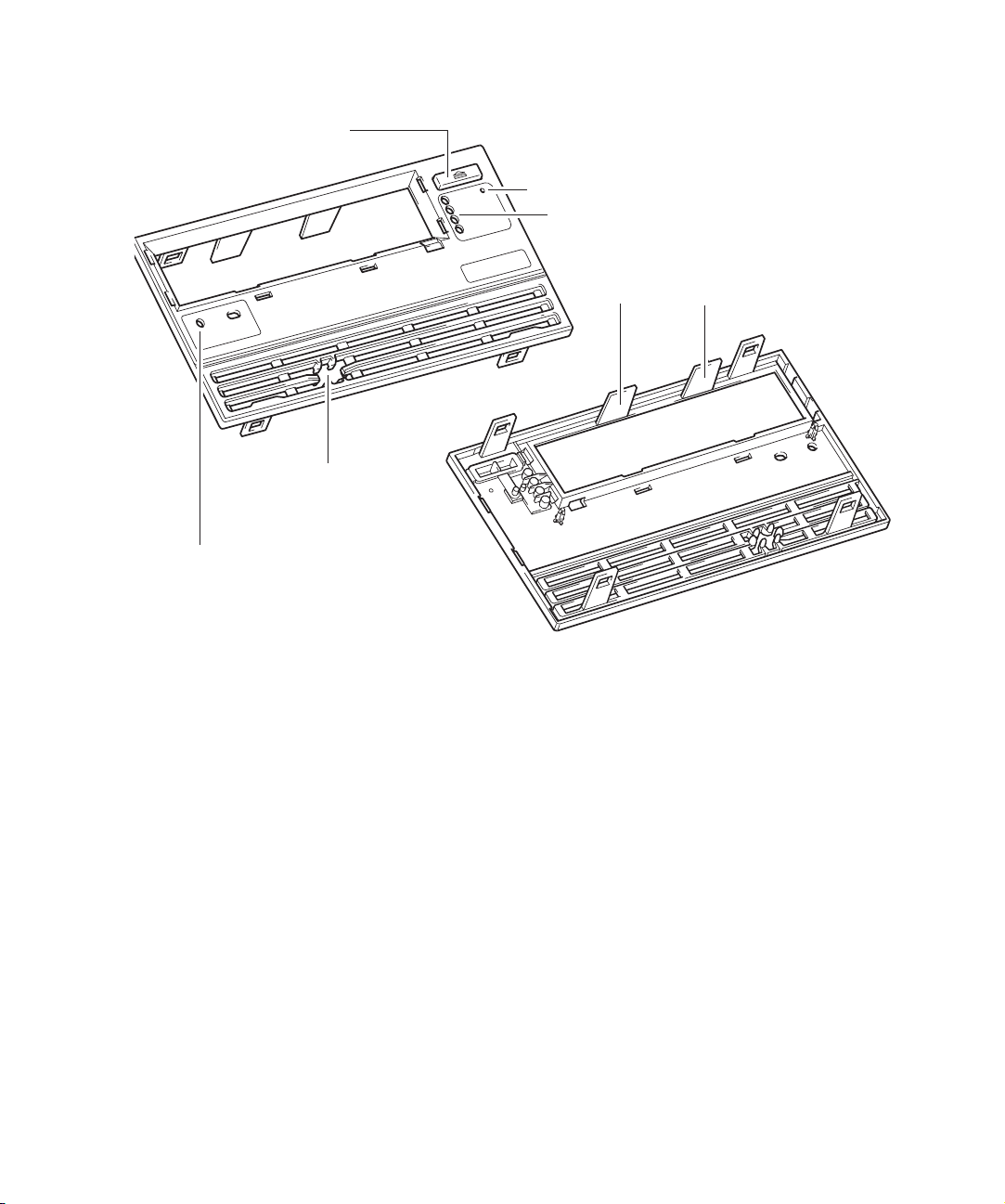
Front panel for automation use
eject button
diagnostic
port access
holestoactas
targets for optical
position sensors
access to emergency reset button
lights
guides to assist with loading
and unloading cartridge
The automation front panel has the following features:
• There is an eject button for manually ejecting a cartridge. Press this for approximately ten
seconds to start a “forced eject” for recovering a cartridge manually. See page 22 for details.
• Indicator LEDs provide a visible indicator of the state of health of the drive. See Chapter 6 on
page 69 for details.
• There is no door. Instead there are two fixed guides to guide the cartridge into the drive.
• There is access to a proprietary serial HP LTO diagnostics port. To access this port via RS232
requires an HP LTO Diagnostics Interface Card. Diagnostic information from the drive such as
power-on hours, tape-pulling hours, error codes, and firmware trace-logs can be accessed by
connecting to the serial communications port on a computer. Please contact HP for further details
on this diagnostics port.
• The indent for a label on the left just under the cartridge opening is left blank, exposing two
holes. These can be used to provide a target for the optical position sensor of a library picker.
• There are additional holes around the cartridge opening to allow a throat to be fitted if
necessary, to help the smooth loading of cartridges.
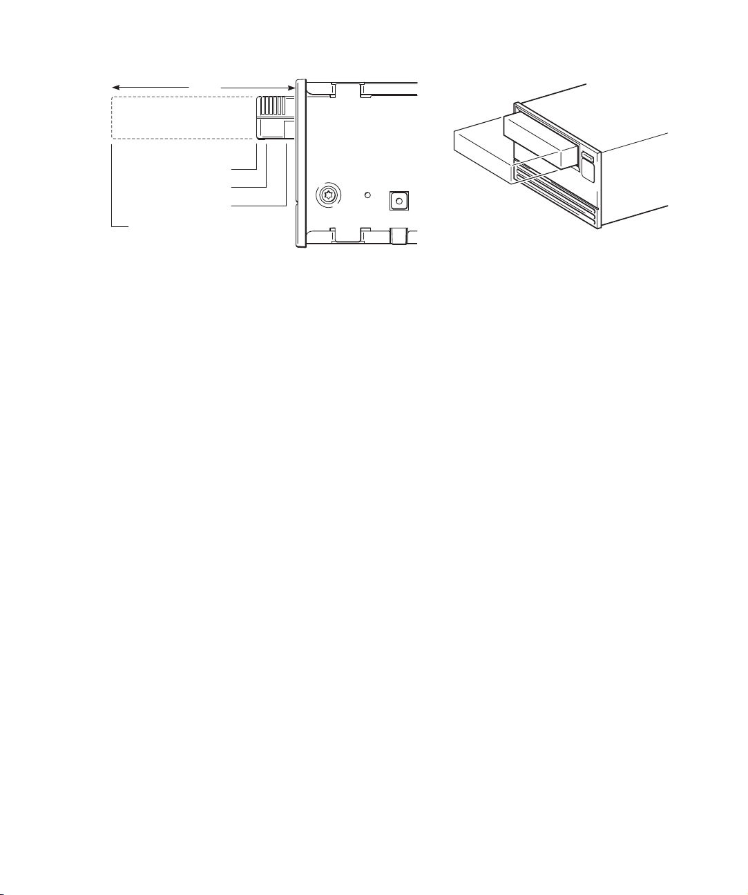
Front panel for use in autoloaders
A special front panel is available for autoloader applications where the autoloader conforms to a
2U product height. The front panel fits within the drive form factor in height and width:
LTO Ultrium drives in libraries14
HP restricted
Page 15
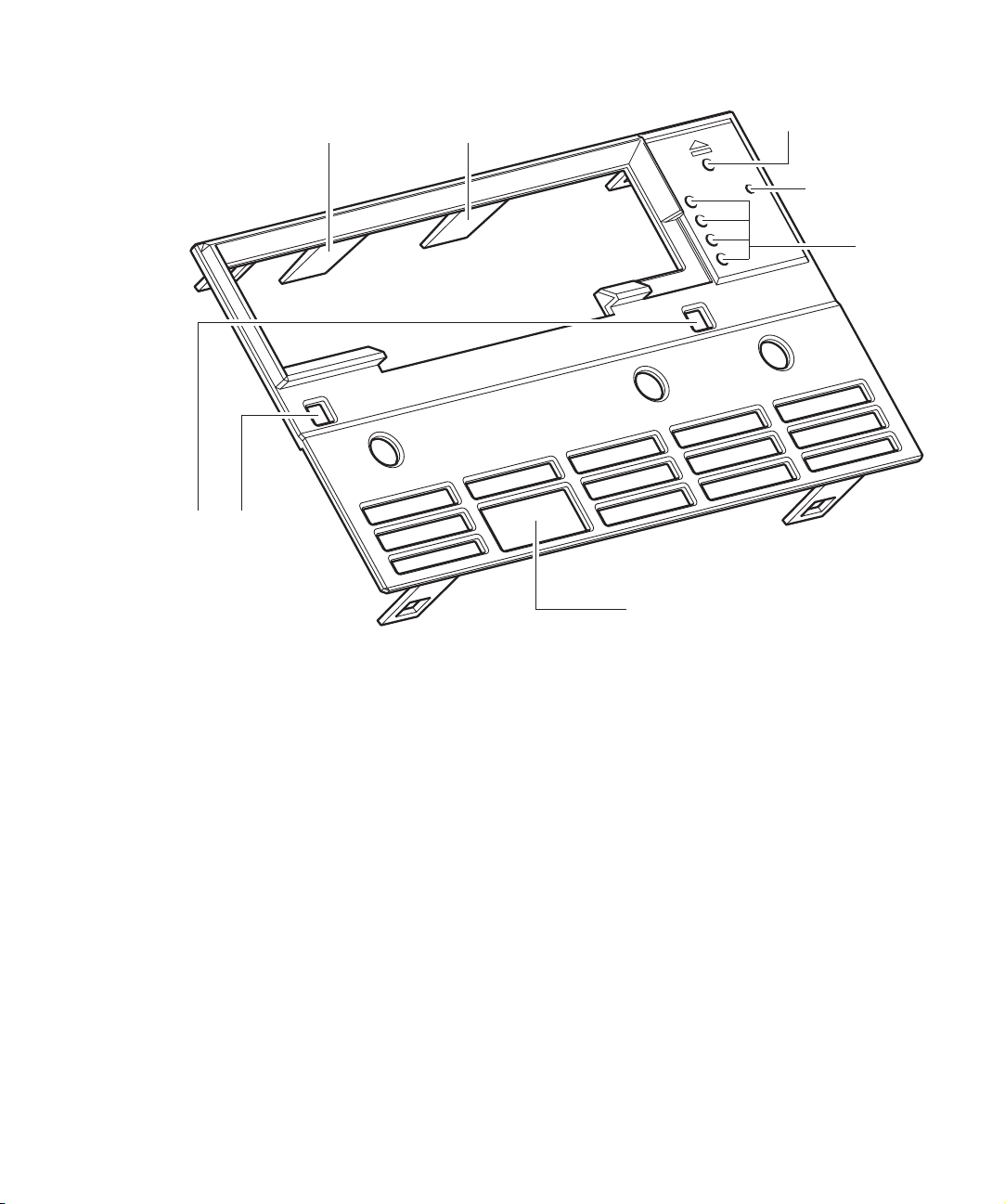
The autoloader front panel has the following features:
guides to assist with loading
and unloading cartridge
access to datum
surface on the front
of the drive
access to
eject switch
access to
emergency
reset button
lights
access to diagnostic port
• Simple one-piece plastic design
• Pinhole access to the eject switch on the drive for manually ejecting a cartridge. Press this for
approximately ten seconds to start a “forced eject” for recovering a cartridge manually. See
page 22 for details.
• Indicator LEDs provide a visible indicator of the state of health of the drive. See Chapter 6 for
details. The LEDs are viewed through holes in the autoloader front panel; no light pipes are
present.
• Access to a proprietary serial HP LTO diagnostics port. To access this port via RS232 requires an
HP LTO Diagnostics Interface Card. Diagnostic information from the drive such as power-on
hours, tape-pulling hours, error codes, and firmware trace-logs can be accessed by connecting
to the serial communications port on a computer. Please contact HP for further details.
• Clearance for picker finger access to the right-side cartridge-handling notch
• Two square holes through the panel to provide access to a datum surface on the front of the
drive
• Cartridge lead-in features to improve cartridge load and unload operations
HP LTO Ultrium 4 drives technical reference manual, volume 1: hardware integration 15
HP restricted
Page 16

Installing drives
Airflow requirements
HP LTO Ultrium drives require forced airflow from front to back and, in the case of full-height drives,
from back to front provided it does not exceed critical temperatures.
The required flow depends on the ambient air temperature:
• 6 cfm for ambient air temperatures fluctuating in the range 10°C–35°C.
• 8 cfm for ambient air temperatures fluctuating in the range 10°C–40°C.
Measuring internal drive temperatures
FC and SCSI drives
The recommended method of measuring the temperature of critical components is to read the “Max
temperature since cartridge loaded” after exercising the drive by writing data at the maximum data
rate for a period of at least one hour. This temperature correlates closely with the temperature of the
most critical ICs.
If the airflow is adequate, the maximum temperature at the sensor should be no more than 20°C
above ambient.
The maximum temperature at the sensor should be:
• <31°C above ambient for 40°C maximum temperature ambient environment
• <36°C above ambient for 35°C maximum temperature ambient environment
This equates to:
• <71°C at 40°C ambient (8 cfm airflow)
• <71°C at 35°C ambient (6 cfm airflow)
Extracting internal temperature information
You can extract the “Max temperature since cartridge loaded” reading via the main interface or via
the ACI/ADI send_scsi command as follows:
1. Send a
1D 10 00 00 08 00
93 00 00 04 00 00 20 2A
2. Send a
1C 01 93 00 44 00
3. The “Max temperature since cartridge loaded” value is ASCII encoded in bytes 22–29 of the
incoming data.
Example SCSI trace:
SendDiagnostic |1D 11 00 00 08 00 |00008|00|00|
ReceiveDiagResults |1C 01 93 01 00 00 |0009C|00|00|
LTO Ultrium drives in libraries16
SEND DIAGNOSTICS command with the following data out:
RECEIVE DIAGNOSTICS command:
Data Out |93 00 00 04 00 00 20 2A |
Data In |93 00 00 98 30 30 30 30 31 41 31 32 20 30 30 30 |
Data In |30 31 41 31 32 20 30 30 30 30 31 41 37 34 20 30 |
HP restricted
Page 17
Data In |30 30 30 31 39 31 37 20 0D 0A 30 30 30 30 30 30 |
Data In |30 30 20 30 30 30 30 30 30 30 30 20 30 30 30 30 |
Data In |33 32 30 30 20 30 30 30 30 30 35 30 30 20 0D 0A |
Data In |46 46 46 46 38 30 30 30 20 46 46 46 46 38 30 30 |
Data In |30 20 46 46 46 46 38 30 30 30 20 46 46 46 46 38 |
Data In |30 30 30 20 0D 0A 46 46 46 46 38 30 30 30 20 46 |
Data In |46 46 46 38 30 30 30 20 30 30 30 30 30 35 30 30 |
Data In |20 30 30 30 30 30 35 30 30 20 0D 0A |
4. Translate each character received from ASCI to hex numbers.
For the example above: 30 30 30 30 31 41 37 34 = 00001A74h
5. Convert this number to decimal = 6772
6. Divide this number by 256 to give the temperature in °C = 26.45°C
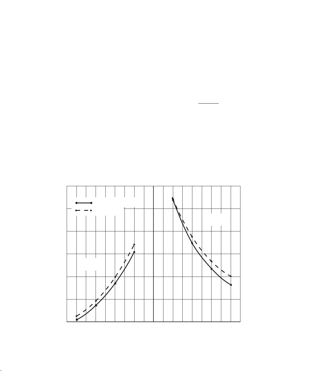
FC and SCSI drives
A method for approximating the air flow for LTO Ultrium drives is to use the drive’s Primary
Temperature Sensor (PTS).
1. Exercise the drive by writing data at the maximum data rate for a period of at least 45 minutes.
2. Find the PTS reading as in the previous section, ”Extracting internal temperature information”.
3. Subtract the ambient air temperature in which the drive was run from this PTS temperature.
4. Use this temperature rise above ambient to find the required air flow for the drive using the
following graph. Because of variations in the temperature sensor (PTS) reading between drives,
you are recommended to average readings from four different drives to obtain the best results.
50
45
SCSI drives
Airflow from
frontto back
Fibre Channel drives
40
35
Airflow from
backtofront
30
Temperature above ambient(ºC)
25
20
–9
–7
–8
–5
–6
–3
–4
–2 –1
0
12
3
5
4
678
9
Airflow(cfm)
HP LTO Ultrium 4 drives technical reference manual, volume 1: hardware integration 17
HP restricted
Page 18

Electrical fit
NOTE: SAS drives should be powered from the normal rear panel connector, not through the
power part of the SAS connector.
The drive is specified to operate at 5V±5% and 12V±10%. Voltage and current requirement are as
follows:
Full-height drives
Specification 5V 12V 5V 12V 5V 12V
Max voltage 5.25V 13.2V 5.25V 13.2V 5.25V 13.2V
Min voltage 4.75V 10.8V 4.75V 10.8V 4.75V 10.8V
Max steady-state current 4.2A 0.75A TBD*A TBDA TBD*A TBDA
Max transient current 4.5A 2.5A TBD*A TBDA TBD*A TBDA
Max steady-state power 21W 9W TBDW TBDW TBDW TBDW
Max transient power 22.5W 30W TBDW TBDW TBDW TBDW
Max noise/ripple 150 mVpp 150 mVpp TBD mVpp TBD mVpp TBD mVpp TBD mVpp
Rear panel and connectors
FC Drives SCSI Drives SAS Drives
CAUTION: LTO Ultrium tape drives are not installable or replaceable by end-users, so the
attachment or removal of FC, SCSI, SAS, power and ADI cables between the tape drive and the
tape library should only be carried out be service-trained personnel authorized by the tape library
supplier. The connectors are not field upgradeable.
The rear panel contains the connectors that allow the tape drive to communicate with the tape
library and host computer system. The panel includes the following connectors:
On all drives:
• Power connector
A standard 4-pin power connector used to supply the 5V and 12V power the tape drive.
• ADI connector (for automation use)
For details of the ADI connector, see page 80. For details of the use of the ADI connector in
libraries see ”Automation/Drive Interface (ADI)” on page 26.
• Diagnostic Serial port connector
The proprietary serial HP LTO diagnostic port. To access this port via RS232 requires an HP LTO
Diagnostic Interface Card. Diagnostic information from the drive can be accessed by connecting
to the serial communications port on a computer. Contact HP for further details on this diagnostic
port and its function.
LTO Ultrium drives in libraries18
HP restricted
Page 19

On Fibre Channel drives:
• Fibre Channel connectors
Two Small Form Factor Pluggable (SFP) duplex-LC fibre channel transceivers. Depending on the
specific configuration, only one SFP FC transceiver may be installed. For details see page 80.
• AL_PA connector
A 2x7-pin auxiliary connector used to set a specific Arbitrated Loop Physical Address (AL_PA).
Two pairs of pins can also be used to power remote transceiver status LEDs. For details see
”Fibre Channel addressing” on page 78.
On SCSI drives:
• SCSI connector
A standard 68-pin high-density SCSI connector. The SCSI cables may be installed in a
daisy-chain configuration linking two or more LTO Ultrium tape drives on the same SCSI bus.
• SCSI address connector
A 12-pin auxiliary connector used to set the SCSI ID. Each device on the SCSI bus must have a
unique SCSI ID set by the SCSI address connector or by the tape library.
On SAS drives:
• A standard internal SAS connector
An HP LTO4 SAS tape drive should be powered from the normal power connector and not
through the power port of the SAS connector. The power port on the SAS connector is not
connected to the tape drive.
Fixing dimensions
The positions of fixing points are shown below.
The recommended screw length depends on the thickness of the rails or enclosure into which the
drive is mounted:
Server or Rail Thickness Recommended Screw Length
> 1.5 mm ≤ 2.0mm M3 x 6.0mm
> 1.0 mm ≤ 1.5 mm M3 x 6.0 mm
≤ 1.0mm M3 x 5.0mm
All screws should be M3 threaded. Do not use spring washers.
The recommended mounting torque is 6.0 ±0.5 in-lbs (60–70 N/cm).
HP recommends 0.3 mm mounting clearance around all covers for isolation mounting movement.
HP LTO Ultrium 4 drives technical reference manual, volume 1: hardware integration 19
HP restricted
Page 20
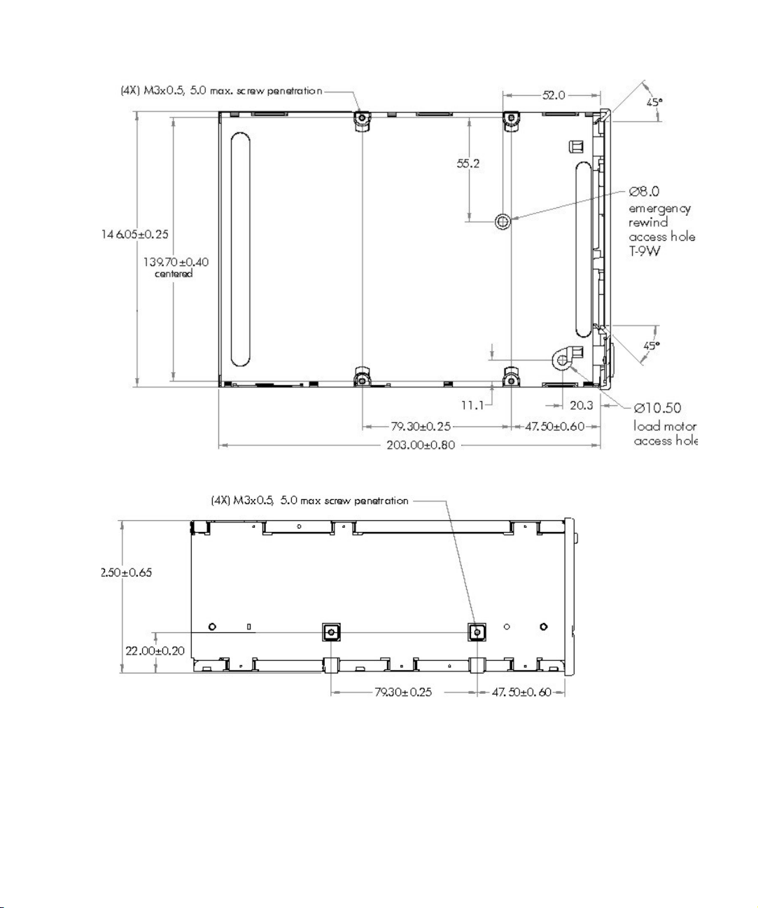
Bottom panel
Side panel
Operating drives
Drives installed in a tape library are controlled through the tape library operator panel. Refer to the
tape library documentation for details.
LTO Ultrium drives in libraries20
HP restricted
Page 21

Cleaning
When the drive needs cleaning, the orange ‘Clean’ LED on the tape drive will flash. Only insert an
HP Ultrium Universal cleaning cartridge into the tape drive when the LED flashes.
The tape drive also tells the automation controller that a cleaning tape needs to be used via the ADI
connector.
See ”Automation and drive interface” on page 25 for details of ACI commands.
CAUTION: Only use LTO Ultrium Universal cleaning cartridges with HP LTO Ultrium tape drives. Do
not use swabs or other means of cleaning the heads.
To clean the heads:
NOTE: HP recommends that you use the HP LTO Ultrium Universal cleaning cartridge C7978A
(Orange).
LTO Ultrium Universal cleaning cartridges can be used up to 50 times.
1. Insert a cleaning cartridge into the drive. The tape drive automatically loads the cartridge and
2. Remove the cleaning cartridge from the drive.
cleans the heads.
If the cleaning cartridge ejects or returns to the ready-to-eject position immediately with the Tape
Error LED on, it has expired or it is not an LTO Ultrium Universal cleaning cartridge (or is an
older unsupported LTO Ultrium 1 cleaning cartridge). In this case, discard the cleaning cartridge
and repeat the operation with a new one.
The cleaning cycle can take up to 3 minutes, during which the orange ‘Clean’ LED will be on
steadily and the green ‘Ready’ LED will flash. When it has finished, the drive ejects the cartridge
or returns the cartridge to the ready-to-eject position.
Resetting drives
The tape drive can be reset by the automation controller via the ADI connector or by pulling the
ACI_RST_L line low (see page 80).
There are two levels of reset via the ADI connector:
• ACI reset—resets the ACI port and all Fibre Channel, SCSI or SAS ports
• Drive reset—equivalent to a power-on reset
Either reset method will interrupt the interface between the drive and host. A reset may result in no
End of Data mark being written. As a result, it is strongly recommended that a reset command is not
sent unless all other recovery methods have failed. Note that certain automation commands (Load,
Unload, Set Drive Configuration, Reset and Set Baud Rate) can be queued behind outstanding SCSI
commands giving the impression that the drive has stopped responding over the ADI connector. (All
command packages will be still be ack’ed even though the command will be queued.)
HP LTO Ultrium 4 drives technical reference manual, volume 1: hardware integration 21
HP restricted
Page 22

Following a Reset command with reset control set to Drive Reset or after pulling the ACI_RST_L line
low, the drive will behave as if it has powered up and will go off bus and lose all ADI connector
configurations.
An FCP reset will not affect the ACI interface.
Note that following an upgrade of the drive firmware, the drive will be reset as if it had been
powered up.
Troubleshooting
If you experience problems when using your tape drive within an automation environment, you need
to isolate the cause of the problem. For example, if you have just installed a new SCSI host bus
adapter in your host system and your system will not start, the cause of the problem is likely to be the
adapter.
The first step in problem-solving is establishing whether the problem lies with the cartridge, the drive,
the tape library, the host computer and its connections, the operating system or backup application
on the host, or operator error.
Please refer to troubleshooting information provided with the tape library, the host or the backup
software if the problem seems to lie in one of these areas.
If none of the following advice helps you solve the problem, contact your tape library supplier.
Diagnostics
HP LTO Ultrium tape drives continuously monitor and gather information such as tape-pulling hours,
power-on hours, usage information on cartridges, firmware trace-logs, and error logs. These can be
used to aid health checks and diagnosis in cases of failure. Data can be extracted via:
• The main host interface
• The ADI connector
• The serial diagnostics port using a proprietary serial interface application.
Contact HP for a copy of the Diagnostics Extraction Guide on extracting and interpreting the
information.
Interpreting the LEDs on individual drives
HP LTO Ultrium tape drives have four LEDs on the front. See Chapter 6 on page 69.
Forced eject
If a cartridge fails to eject using the normal unload procedure, press and hold the Eject button for
10 seconds. This instructs the drive mechanics to perform an emergency unload. Wait for the
cartridge to be ejected. This may take up to 15 minutes (the maximum rewind time).
If the cartridge is still jammed, press the emergency reset button (see page 14) or perform an
emergency reset by pressing and holding the Eject button for 20 seconds. The drive will reset when
you release the button. Wait for the drive to reset and get back to the loaded position. This may take
up to 15 minutes. Again press and hold the Eject button for 10 seconds to perform a second forced
eject and emergency unload.
LTO Ultrium drives in libraries22
HP restricted
Page 23

Cleaning issues
Use the following table to resolve cleaning problems:
Problem Solution
Recurring cleaning
message.
A brand new data cartridge
is used, and the library
operator panel indicates
that cleaning is required.
The cleaning cartridge is
ejected immediately after
loading.
Clean the drive with an LTO Universal Cleaning Cartridge as
instructed in the tape library documentation. If the message
reappears, replace the cleaning cartridge with a new one.
If the message reappears when a particular data cartridge is used,
verify that the data cartridge is readable by clearing the message
and reading the tape again.
If the data cartridge can be read, back up the data to another
cartridge and then discard the damaged one.
Clean the outside of the data cartridge with a barely damp, clean,
lint-free cloth. Clean the drive as instructed by your tape library
documentation.
If the operator panel indicates cleaning is required within a short
period of time, replace the data cartridge.
Make sure that you are using an approved LTO Ultrium Universal
cleaning cartridge and that the cleaning cartridge is not expired.
HP LTO Ultrium 4 drives technical reference manual, volume 1: hardware integration 23
HP restricted
Page 24

LTO Ultrium drives in libraries24
HP restricted
Page 25

2 Using special features in libraries
Introduction
This chapter contains information that relates to placing an HP LTO Ultrium drive in an automated
device, such as an autochanger or a tape library.
• The “Automation and drive interface” described below allows the activities of the drive to be
coordinated within a library.
• “Configuring autoload and library-controlled loads” on page 27 tells you how to configure
whether automatic or library-controlled loads and unloads occur.
• “Using Cartridge Memory (LTO-CM)” on page 30 describes the EEPROM embedded in every
LTO Ultrium tape cartridge, part of which is available for use by applications.
Drives for inclusion in automated devices have different front panels from individual drives.
Automation and drive interface
The interface between the tape drive and the library will support both the Automation Control
Interface (ACI) and the Automation/Device Interface (ADI) standards. Typically the interface support
will be an OEM selection. For convenience, the connector is referred to as the ADI Connector in this
manual.
NOTE: ADI is covered by two T10 standards:
• For ADT: ANSI INCITS 406-2005
• For ADC: ANSI INCITS 403-2005
Automation Control Interface (ACI)
The Automation Control Interface (ACI) allows the activities of the drive to be coordinated within a
library. The protocol has been designed so that it can be made into a standard feature of tape
drives. It provides a rich and extensible functionality to allow automation manufactures to add value
in their application of it.
The interface is a serial bus with additional control lines, designed to connect the LTO Ultrium tape
drive to an automation controller in a tape library. Each tape drive position has a separate
automation controller. The ADI RS-422 serial port on the rear of the drive allows for ACI connection.
The ACI protocol provides the following fundamental functions:
• Coordinating the automation controller and the tape drive for Load and Unload operations
• Allowing the automation controller to retrieve information from the tape drive
• Setting tape drive configuration information
In addition, the following functions may be supported depending on the way that the tape library is
configured:
HP LTO Ultrium 4 drives technical reference manual, volume 1: hardware integration 25
HP restricted
Page 26

• Providing upload and download of firmware images
• Providing access to the contents of the Cartridge Memory
• Providing a protocol for passing SCSI commands from the host to the tape drive
• Providing a protocol for passing SCSI commands from the host to the library (Surrogate SCSI)
NOTE: These notes refer to the “standard” automation drive variant.
For details of using ACI commands and the ACI protocol, see Chapter 5 of the Software Integration
Guide, volume 2 of the HP LTO Ultrium Technical Reference Manual.
Automation/Drive Interface (ADI)
The INCITS T10 (SCSI) committee has a working group devoted to the development of a common
Automation-Drive Interface (ADI). ADI consists of two standards:
• Automation/Drive Interface—Commands (ADC), ANSI INCITS 406-2005, which specifies the
SCSI command set used over ADI.
• Automation/Drive Interface—Transport Protocol (ADT), ANSI INCITS 403-2005, which specifies
a transport protocol for ADI.
The drive operates in either ACI or ADI mode. It is not possible to interleave ACI and ADI
commands because they are handled very differently. The drive defaults to ACI mode after a
power-on or hard reset. The Automation Controller can then instruct the tape drive to switch to ADI
mode by sending a Port Login frame under the following conditions:
1. No ACI commands are outstanding. This not only means that the tape drive must have received
acknowledgement for all responses to all ACI commands received, but also that all immediate
response commands have also finished. For example, if an Automation Controller initiates an
immediate response Load command (see section 5.3 of ACI specification), it cannot issue an
ADI command until the tape drive has finished physically loading the cartridge. If an ACI
command is outstanding when an ADI frame is received the drive will transmit an ACI <NAK>
character in response.
2. An Encoded ADI frame received when the tape drive is in ACI Mode must not exceed the
Receive Buffer size (see section 5.16 of the ACI Specification for details) and the frame must be
received within the ACI Transmission Period (see section 4.6.6.3.2 of the ACI Specification). If
either of these conditions is exceeded the tape drive will transmit a <NAK> character.
3. ADI frames received in ACI Mode must be Port Login frames otherwise the tape drive will revert
to ACI Mode after transmitting the appropriate ADI response.
4. The ADI protocol must be enabled; see the Set Drive Configuration command (section 5.6 of the
ACI Specification) for details. If the tape drive receives an ADI frame when the ADI protocol has
been disabled the drive will transmit a <NAK> character.
When the tape drive is in ADI Mode it will not acknowledge or respond to any ACI command until
the ADI port becomes logged out, either with an explicit Port Logout frame or an ADI Reset.
When the tape drive transitions from one mode to the other (ACI to ADI or ADI to ACI) it will not
implicitly change the drive’s configuration. However, Automation/Drive Interface [ADC] SCSI mode
Using special features in libraries26
HP restricted
Page 27

parameters only apply when the tape drive is in ADI Mode, so the tape drive behavior may change
after transitioning between the two modes.
HP recommends that the drive is used in either exclusively ACI or ADI modes of operation. Avoid
mixing operation of the two modes.
Configuring autoload and library-controlled loads
HP LTO Ultrium tape drives can be configured so that loads either occur automatically or under the
control of the library. A SCSI
is byte 5, bits 0–2 of the Control Mode page, 0Ah.
If the Autoload field = 0, Autoload is set and the drive automatically loads a cartridge when it is
inserted and threads the tape so that it is ready for use.
MODE SELECT command can set the Autoload field to do this. The field
If the Autoload field = 1 or 2, the drive pulls the cartridge into the drive but does
tape. In this position, the LTO-Cartridge Memory can be read. The drive requires a Load command
to thread the tape and make it ready for use.
Cartridge positions during load and unload
The following diagrams show the positions of importance during load and unload.
not thread the
HP LTO Ultrium 4 drives technical reference manual, volume 1: hardware integration 27
HP restricted
Page 28
Full-height drives
50 mm
5 mm
10 mm
5 mm
eject point
load point1
load point2
cartridge present point
SCALE 25%&50%
Eject Point Cartridges are ejected to this point. It is 20.9 mm beyond the front panel
and 26.1 mm beyond the front of the mechanism. The position tolerance is
±1 mm. The automation controller cannot configure the location of this
position.
Load Point 1 If Autoload is set (Autoload field = 0), the drive will start to load the
cartridge when it reaches this point.
If Autoload is not set (Autoload field = 1 or 2), the library must insert the
cartridge into the drive to a position between Load Point 1 and Load Point 2
and preferably closer to Load Point 1. The library can then issue a Load
command via the ADI connector to instruct the drive to load and thread the
cartridge.
Load Point 2 The maximum distance a cartridge can be inserted for optimal loading
There is one other point of note, the ready-to-eject position. If Auto-Eject is not set then when an
unload command is received by the drive, the tape will be rewound and unthreaded. The drive will
then wait at this point until it is commanded to eject the cartridge by the ACI Unload command.
Load scenarios
The following scenarios describe the operation during the various types of load.
Load scenario 1: Autoload
1. The library sends a Set Configuration command to enable Autoload. This is only necessary after
a drive power-on.
2. The host sends a Move Medium command to the robotics.
Using special features in libraries28
The maximum speed for inserting a cartridge into the drive is 80 mm/s.
Load Point 1 is the recommended minimum load point for commanded
loads. It is 15 mm beyond the front panel with a –2 mm tolerance.
performance, so that autoload or a Load command can load the cartridge. It
is 5 mm beyond the front panel. The automation controller cannot configure
the location of this position.
The maximum speed for inserting a cartridge into the drive is 80 mm/s.
HP restricted
Page 29

3. The picker gets a cartridge from a storage slot.
4. The picker inserts the cartridge into the drive aperture.
5. The picker pushes the cartridge to at least Load Point 1.
6. The drive automatically takes the cartridge, loads it and threads it.
Load scenario 2: Library controlled
1. The host sends a Move Medium command to the robotics.
2. The picker gets a cartridge from a storage slot.
3. The picker inserts the cartridge to between Load Point 1 and Load Point 2.
4. The picker lets go of the cartridge.
5. The library sends a Load command to the drive.
6. The drive takes the cartridge, then loads and threads it.
Unload scenario 1: Autoload
1. The library sends a Set Configuration command to enable Auto-Eject. This is only necessary after
a drive power-on.
2. The host sends an Unload command to the tape drive.
3. The drive rewinds, unthreads and ejects the cartridge to Eject Point.
4. The host sends a Move Medium command to the robotics.
5. The picker takes the cartridge from the tape drive and places it in its storage slot.
Unload scenario 2: Library controlled
1. The host sends an Unload command to the drive.
2. The drive rewinds and unthreads the tape. It then pauses with the cartridge at ready-to-eject
position.
3. The library sends an Unload command to eject the cartridge.
4. The drive ejects the tape to Eject Point.
5. The picker takes the cartridge from drive and places it in its storage slot.
Load forces
The unload force is 4.45N maximum; this is the force that an external mechanism must exert to
remove a fully ejected cartridge from the drive.
The load force varies according to the speed at which the cartridge is inserted into the drive. The
peak load force occurs when the cartridge begins to accelerate the drive carrier and only lasts for a
short time. The following graph plots examples of peak load force against load speed:
Figure 1 Peak load force versus load speed
HP LTO Ultrium 4 drives technical reference manual, volume 1: hardware integration 29
HP restricted
Page 30

Using Cartridge Memory (LTO-CM)
Linear Tape Open—Cartridge Memory (LTO-CM) is an EEPROM that is embedded in every LTO
Ultrium tape cartridge. It is non-volatile and is contactless in that it is read by inductive coupling
rather than electrical contact.
The Cartridge Memory is used to store the tape directory and diagnostic and log information.
Because of the speed at which it can be read, load and unload times are reduced, information is
found on the tape more quickly and fewer tape passes are needed, increasing tape reliability.
The memory is primarily designed to speed up internal operations in the drive, but it also contains
free space that can be used by application software. This may be used to store “common”
information (shared by all software vendors) and “vendor-unique” information (specific to the
application).
Hosts can use this free space using the SCSI Write Attribute and Read Attribute commands. For
information on these commands, see Chapter 4 of Interface Guide, Volume 3 of this HP LTO Ultrium
Technical Reference Manual.
To support CM fully, software vendors should ensure that their company names are registered with
ANSI T10 or the National Committee for Information Technology Standards (NCITS) as they are
now known. The list of Vendor IDs is displayed at http://www.t10.org/lists/vid-alph.htm
also contains details of how to get a new name assigned.
Cartridge Memory adheres to the Media Auxiliary Memory (MAM) standard. “MAM” indicates
that the access method applies to all types of media, not just LTO Ultrium.
The MAM standard provides for the storage and access of information held as a set of pre-defined
and user-definable attributes that are divided into six main sections:
, which
• Media Common Section—hard-coded by the media manufacturer.
For example: manufacturer’s name, cartridge serial number, length, media type
Using special features in libraries30
HP restricted
Page 31

• Drive Common Section—updated by the drive every time it accesses the media.
For example: maximum and remaining tape capacity, TapeAlert flags
• Host Common Section—updated by the host’s software application every time it uses the media.
For example: software application vendor’s name and version, media text label, date last written
• Media Vendor Unique Section—optional information written by the media vendor for their own
purposes. Unique to the media vendor.
• Media Vendor Unique Section—optional information written by the media vendor for their own
purposes. Unique to the media vendor.
• Host Vendor Unique Section—space reserved for use by software applications for their own
purposes. Unique to the software vendor. Approximately 1 kilobyte.
For details of SCSI commands relating to Cartridge Memory or MAM, see Read Attributes (8Ch)
and Write Attributes (8Dh) in the Interface Guide.
Use in libraries
Cartridge memory offers possibilities for use in libraries as an adjunct to or replacement for
barcodes. The following diagram shows the architecture required. HP is working to provide a
standard module with this functionality via a third party.
Drive or Library Ultrium Cartridge
Controller
Demodulator/
Buffer
SPI
Interface
Host
Current libraries — barcodes
Many libraries use sticky labels with barcodes on cartridges to identify them. These are read by a
barcode reader attached to the picker arm. The application then needs to hold information as to the
contents of the tape to which it can relate the bar code.
Encoder/
Modulator
Decoder
LTO-CM
Reader IC
coupling
Tuning Circuit
RF
Demodulator/
Decoder
Encoder/
Modulator
LTO-CM
Transponder IC
Controller
4 KB EEPROM
(128x32 byte)
Cartridge Memory can be used as a substitute for these barcodes. No human interaction is needed
to fix barcode labels, reducing errors, though cartridges may still need labels that humans can read.
A cartridge can be identified by its serial number.
HP LTO Ultrium 4 drives technical reference manual, volume 1: hardware integration 31
HP restricted
Page 32

However, because Cartridge Memory has space that can be written by applications, it can hold
details of the contents and nature of the tape. This obviates the need for this information to be held
by the application. HP is working with other industry leaders, both hardware and software, on an
Industry Common Implementation Guide.
More information
• The latest version of the specification is incorporated into SCSI SPC-3.
• The access specification can be found at http://www.t10.org/
.
Using special features in libraries32
HP restricted
Page 33

3 Drives in tape arrays
Installing drives
Identifying the drive
The model name is on the front panel and the product and serial numbers are on a label attached
to the drive.
Modes of usage
Tape arrays can be used in different system configurations; direct attach, network attach and
attached to a Storage Area Network (SAN). For details of these see page 83.
Attaching to Fibre Channel
When installing a SCSI drive on a fibre channel direct attach network or SAN configuration, you
need a fibre channel/SCSI router. Check www.hp.com
manual does not describe how to configure your fibre channel infrastructure or SAN network to use
the tape array. This is a complex area and users are advised to refer to their SAN documentation or
contact their SAN system administrator or supplier for technical support.
Attaching to SCSI
HP LTO Ultrium SCSI drives are high performance Ultra 3 SCSI devices designed to operate on a
low voltage differential SCSI bus (LVDS). They are installed in a tape array in a rack-mount system
and can be connected to a SCSI connection on a server or fibre channel/SCSI router. To get
optimum performance from your tape drive you need a SCSI bus that can transfer data at a rate that
supports the tape drive’s maximum transfer speed. We recommend an Ultra 3, 160 and 320 SCSI
bus.
for the latest ordering information. This
Attaching to SAS
HP LTO Ultrium SAS drives are high performance 3 GB SAS devices. When installed in a tape array
in a compatible rack mount system they can be connected to a SAS connection on a server or to an
expander as part of a larger SAS network. To get the optimum performance from your tape drive
you need a SAS topology that can transfer data at a rate that supports the tape drive's maximum
transfer speed.
Appropriate HP rack-mount systems
HP LTO Ultrium removable tape drives are used in conjunction with the HP StorageWorks Tape
Array 5300 system, which will hold up to two full-height drives.
The tape array is designed to be installed into any compatible 19” rack-mount systems. It must be
properly installed and configured. Refer to your tape array documentation for further details.
Airflow requirements
As long as the tape array is fully populated, it will provide adequate airflow for HP LTO Ultrium
drives.
HP LTO Ultrium 4 drives technical reference manual, volume 1: hardware integration 33
HP restricted
Page 34

If you have unused bays in the tape array, you must install the blanking plates provided with the
tape array. This ensures that there is adequate airflow to the drives. See the documentation with the
tape array for details on installing blanking plates.
You should ensure that ventilation is adequate at the front and rear of the tape array.
HP LTO Ultrium drives require forced airflow, either from front to back or from back to front.
The required flow depends on the ambient air temperature:
• 6 cfm for ambient air temperatures fluctuating in the range 10°C–35°C.
• 8 cfm for ambient air temperatures fluctuating in the range 10°C–40°C.
For details of how to test if the airflow is adequate, see “Airflow requirements” on page 16.
Setting the SCSI ID
For removable drives installed in an HP StorageWorks Tape Array 5300 rack enclosure, set the SCSI
ID at the appropriate switch on the rear of the tape array. Each drive should have a unique ID. The
number of address switches corresponds to the number of tape drives that can be inserted into the
tape array, so the HP StorageWorks Tape Array 5300 has four SCSI ID switches to enable the
installation of up to four half-height tape drives. When installing two HP LTO Ultrium full-height tape
drives, use the SCSI ID switches 1 and 2 only.
Termination
Both ends of a SCSI bus must be terminated.
Assuming that the host bus adapter is already correctly terminated, there are typically two
possibilities:
• The tape drive is being connected in a direct one-to-one configuration to the host
server—termination must be used.
• The tape drive is being daisy-chained with other tape devices onto the host server—only the last
device must be terminated.
The terminator can be plugged directly onto either of the two SCSI connectors on the rear of the
tape array. Terminators must be ordered separately.
Drives in tape arrays34
HP restricted
Page 35

Inserting a drive
1. Ensure that the extractor lever on the drive is in the
out position, as shown in the picture.
2. Lift the drive carefully.
3. Align the rear of the drive with the guides on the side
of the HP StorageWorks Tape Array 5300.
4. Slide the drive along the guides until the connectors
on the back mate with the connectors at the back of
the enclosure.
5. Push the extractor lever in until it locks the drive in
position.
Connecting to a Fibre Channel router or by SCSI/SAS to a server or router
Individual SCSI tape drives are connected to their host server or fibre channel router via the high
density LVD/SE SCSI connectors on the back of the tape array. They do not require any SCSI cables
to plug into the tape array. However, cabling and terminators are required to connect the tape array
with the SCSI host.
Individual SAS tape drives are connected to their hosts via the SAS connectors on the back of the
tape array. They do not require any SAS cables to plug into the array. However, cabling is required
to connect the tape array with the SAS host or expander.
Fibre Channel connection
If you are using your SCSI tape drive on a fibre channel (FC) network, you will need a FC/SCSI
router with a spare LVDS SCSI port. The router should be connected via a 68-pin, wide, LVDS-rated
cable to the tape array. Refer to our web site at www.hp.com/go/connect
recommended FC/SCSI routers and cables. If you are attaching your tape drive to a SAN
environment supplied by HP, refer to your SAN solution collateral or configuration guides for further
details.
Server SCSI connection
If you are attaching the drive to a server, you will need a properly installed and configured SCSI
host bus adapter (HBA) or a built-in SCSI controller on your server with a spare LVDS SCSI port. For
optimum performance your tape drive should only be connected to an Ultra 3, 160 or 320 host bus
adapter or SCSI controller.
The server should be connected via a 68-pin, wide, LVDS-rated cable to the tape array. The
standard, recommended configuration is a direct, one-to-one SCSI connection between the tape
drive and the host server so that the drive is the only device on the SCSI bus. It is possible to
daisy-chain two tape drives together within the tape array, but to preserve performance, this should
only be done if the drives are on an Ultra 3, 160 or 320 SCSI bus. Do not daisy-chain more than
two drives together, as this will degrade their individual performance with respect to transfer rate.
Do not attach the drive to the same SCSI bus as your disk drive or RAID controller.
HP LTO Ultrium 4 drives technical reference manual, volume 1: hardware integration 35
for details of
HP restricted
Page 36

Server SAS connection
If you are attaching the drive to a server, you need a properly installed and configured SAS host bus
adapter (HBA) or a built-in SAS controller on your server with a spare SAS port. For optimum
performance your tape drive should only be connected to a 3 GB SAS host bus adapter or SAS
controller, but the drive will also work with a 1.5 GB SAS connection.
Replacing a drive
HP LTO Ultrium removable drives can be removed and replaced without powering down the tape
array and without interrupting operations to the other drives in the array. However, note the
following:
• In Berkeley mode, the tape position will remain unchanged by a device close operation.
• In AT&T mode, a device close operation will cause the tape to be repositioned just after the next
tape filemark (the start of the next file).
If all drives in the tape array are powered up when the system is turned on, the host will be aware of
those drives. You can remove any drive and replace it with another without disrupting the system.
If a drive is not powered up or you place a drive in an empty slot after the system has been powered
up, the system will have to be reset before the host will recognize the drive.
Removable drives allow modules to be replaced while powered up as long as no data is being
transmitted from the system to the module or vice versa. The SCSI IDs are controlled by the tape
array, not the drives, so if you remove a drive and replace it with another the ID will not change.
Removing a drive
Installing a new drive
See the instructions in “Inserting a drive” on page 35.
Operating the drive
Removable drives are powered on when you switch on your tape array and computer.
Drives in tape arrays36
1. Pull the extraction lever of the drive that you want to
replace so that it is in the out position.
2. Using the extraction lever, pull the drive gently and
firmly out of the tape array.
HP restricted
Page 37

The tape drive will run its hardware self-test. During the test the ‘Ready’ LED flashes and all the other
LEDs are off. On successful completion the ‘Ready’ LED is on. If the self-test fails, the ‘Drive Error’
and ‘Tape Error’ LEDs flash, while the ‘Ready’ and ‘Clean’ LEDs are off. This continues until the drive
is reset.
• If you have just installed the drive, check the installation for loose connections, reset the drive
and repeat the self-test.
• Try the “Troubleshooting” on page 39 to determine what the problem is.
• If the fault condition persists, call for assistance.
Front panel features
LEDs
eject button
readylight
driveerrorlight
tape error light
clean light
For details of the front panel LEDs, see page 69.
HP LTO Ultrium 4 drives technical reference manual, volume 1: hardware integration 37
HP restricted
access to
reset switch
Page 38

Reset switch
The emergency reset switch allows you to reset the drive without powering off the drive and
computer, for example if the drive stops responding. Access to the switch is through a small hole. It
can be activated by a thin object, such as the end of a straightened paper-clip.
Loading a cartridge
Use HP LTO Ultrium cartridges with your drive.
1. In HP StorageWorks Tape Arrays:
Insert the cartridge into the slot in front of the drive with the white arrow on the top facing the
drive door. The toothed drive hub is on the bottom of the cartridge.
2. Apply gentle pressure on the rear of the cartridge until the drive takes the cartridge and loads it.
The ‘Ready’ LED flashes green while the drive performs its load sequence. When the cartridge is
loaded, the ‘Ready’ LED shows steady green.
Do not try to force the cartridge if it does not load properly. The drive will eject the cartridge after
about 10 seconds so you can load it again.
Unloading a cartridge
1. Press the Eject button on the front panel.
During the unload sequence the ‘Ready’ LED flashes green. The drive completes any task it is
Drives in tape arrays38
HP restricted
Page 39

currently performing, rewinds the tape and ejects the cartridge. Once the tape has rewound, the
eject cycle will take less than 13 seconds.
2. Remove the cartridge and store it in its plastic case in a cool, dry atmosphere.
Cleaning the drive
CAUTION: It is essential to use only LTO Ultrium Universal cleaning cartridges with HP LTO Ultrium
tape drives as other format cleaning cartridges will not load and run. Use of HP cleaning cartridges
will ensure your tape drive is fully protected.
Do not use swabs or other means of cleaning the heads.
When the drive needs cleaning, the orange ‘Clean’ LED on the tape drive will flash. Only insert a
cleaning cartridge into the tape drive when the LED flashes.
The drive’s TapeAlert feature will send a message to your backup application when the tape heads
need cleaning or a cleaning cartridge has expired.
LTO Ultrium Universal cleaning cartridges can be used up to 50 times.
To clean the heads:
1. Insert a cleaning cartridge into the drive. The tape drive automatically loads the cartridge and
cleans the heads.
If the cleaning cartridge ejects immediately, it has expired or it is not an LTO Ultrium Universal
cleaning cartridge (or is an older LTO Ultrium 1 cleaning cartridge). In this case, discard the
cleaning cartridge and repeat the operation with a new one.
The cleaning cycle can take up to 3 minutes, during which the orange ‘Clean’ LED will be on
and the green ‘Ready’ LED will flash. When it has finished, the drive ejects the cartridge.
2. Remove the cleaning cartridge from the drive.
Troubleshooting
Emergency unload
If a cartridge fails to eject using the normal unload procedure, press and hold the Eject button for
10 seconds. This instructs the drive mechanics to perform an emergency unload. Wait for the
cartridge to be ejected. This process may take up to 15 minutes (the maximum rewind time).
If the cartridge is still jammed, press the emergency reset button (see page 38). Wait for the drive to
reset and get back to the loaded position. This process may take up to 15 minutes (the maximum
rewind time). Again press and hold the Eject button for 10 seconds to perform an emergency
unload.
General guidelines
The first step in problem-solving is establishing whether the problem lies with the cartridge, the drive,
the host computer and its connections, or with the way the system is being operated.
Most modern host bus adapters locate and display attached devices when the system is booting up.
On Windows systems, if you swap or connect a product when your system is running, you will need
HP LTO Ultrium 4 drives technical reference manual, volume 1: hardware integration 39
HP restricted
Page 40

to reboot the system. IA32 systems also usually need to be rebooted. UNIX systems may have
pluggable drivers, which allow drives to be attached to a running system and detected without
rebooting.
If the device is not detected on boot up, there is probably a problem with the physical hardware:
cables, termination, connections, power or the host bus adapter. If the device is displayed during
boot up but cannot be found in the operating system, this is more likely to be a software problem.
Problems with the host computer
Most modern host bus adapters locate and display attached devices when the system is booting up.
If the device is not detected at this stage, there is probably a problem with the physical hardware:
cables, termination, connections, power or the HBA itself.
If your drive is found on system boot up but cannot be found in the operating system, this is more
likely to be a software problem.
Computer does not boot up
Possible Cause Potential Solution
You have connected the tape drive to an existing
SCSI bus that has other devices connected to it and
the SCSI address of the drive is identical to the
address used by another device.
You have installed an additional host bus adapter
and its resources are clashing with an existing
adapter.
You have disconnected the power or cable from the
computer’s boot disk during the drive installation
process.
Computer boots, but does not recognize the drive
Possible Cause Potential Solution
The power or interface
cable is not connected
properly.
The SCSI bus is not
terminated correctly.
Check that the cables to the tape drive are firmly connected. Ensure
that the interface cable is LVDS-compliant and that it does not have any
bent pins or is damaged. Replace, if necessary.
Check that the SCSI bus is actively terminated. (Refer also to the
documentation for your SCSI controller and any other SCSI devices you
may have.)
Make sure that each device on the SCSI
bus has a unique ID. We recommend that
the tape drive is connected to a dedicated
host bus adapter. Do not connect the drive
to a disk RAID controller as this is not
supported.
Remove the new host bus adapter and
check the server documentation.
Check that the cables to all devices are
firmly connected.
The tape drive’s SCSI ID
address is not unique.
Drives in tape arrays40
Make sure that each device connected to the SCSI controller has a
unique SCSI ID. Remember that 7 is normally reserved for the host bus
adapter.
HP restricted
Page 41

Problems with the drive and cartridge
Tape drive does not work
Possible Cause Potential Solution
The drive is not
receiving power from
the tape array.
• Check the tape array is connected to a power source and switched
on.
• Check the drive is properly inserted into the tape array so that it
mates with the connections at the rear of the enclosure. The
extraction lever should be pushed in, locking the drive in position.
• If the drive ‘Ready’ LED is still off, call for assistance.
There is a fault with the
drive.
If possible, and if no other drives in the tape array are in use, try
resetting the drive, or turning the power switch on the tape array off
and then on again. (If there is a tape cartridge loaded in the drive, try
to unload it by pressing the Eject button. If this succeeds, switch the
tape array off and then on again.
If the problem persists, call for assistance.
The computer no longer recognizes the drive
Possible Cause Potential Solution
You powered up the drive
or added it to the tape
array after the host system
was turned on.
You changed the drive’s
SCSI ID after the host
system was turned on.
The host computer system only identifies which IDs are present on SCSI
buses after power-on or a reset. To make the host look for devices on the
bus, you need to reset the host. You should be able to do this using the
SCSI management software on your computer. As a last resort, you could
turn the host system off and on again
• If you have replaced a drive that was recognized by the host, the
host should recognize the new drive at the same SCSI ID as its
predecessor.
• If you make any changes to SCSI IDs (on the back on the tape
array), you need to reset the bus for the host to recognize the
changes.
.
The drive is not inserted
correctly.
HP LTO Ultrium 4 drives technical reference manual, volume 1: hardware integration 41
Check the drive is properly inserted into the tape array so that it mates
with the connections at the rear of the enclosure. The extraction lever
should be pushed in, locking the drive in position.
HP restricted
Page 42

Possible Cause Potential Solution
The SCSI bus is not
terminated correctly.
• Check the SCSI cable from the tape array is firmly connected to
the SCSI connector in the computer.
• If there are other devices in the SCSI bus, make sure that each
device has a unique ID.
• If there is more than one SCSI bus attached to your system, check
that the system is looking for the drive on the correct SCSI bus.
• Make sure that the bus is terminated correctly. If the array is the
only device or the last device on the bus, it must have a terminator
fitted. If some other device is last on the bus, it should have a
terminator fitted and the tape array should not.
There is a fault with the
host system.
• Make sure that the system is configured to recognize the correct
device at each SCSI ID.
• Ensure that the correct driver for the tape drive is installed. Look at
the SCSI host adapter documentation and backup software
documentation for further advice.
The application does not recognize the drive
Possible Cause Potential Solution
The application does
not support the tape
drive.
Check the drive is installed properly. Refer to our World Wide Web site
(www.hp.com/go/connect
support HP LTO Ultrium tape drives. Load any service packs as
necessary.
) for details of backup applications that
Some applications
require drivers to be
loaded.
Drives in tape arrays42
Check the correct HBA and tape drive drivers are installed. Consult the
backup application’s installation notes for details.
HP restricted
Page 43

The cartridge will not eject
Possible Cause Potential Solution
The cartridge is jammed
in the drive, or the
backup application
cannot eject the
cartridge.
This is most likely to be a
communication problem
between the drive and
the system.
Check there is power to the drive.
If the cartridge fails to eject using the normal unload procedure, press
and hold the Eject button for 10 seconds. Wait for the cartridge to be
ejected. This may take up to 15 minutes (the maximum rewind time).
If the cartridge is still jammed, perform an emergency reset by
pressing and holding the Eject button for 20 seconds. The drive will
reset when you release the button. Wait for the drive to reset and get
back to the loaded position. This may take up to 15 minutes. Again
press and hold the Eject button for 10 seconds to perform a second
forced eject.
If the cartridge is still jammed, call for support.
The drive will not accept a cartridge or ejects it immediately
Possible Cause Potential Solution
The cartridge may have
been damaged, for
example dropped, the
cartridge memory may be
corrupted or the drive may
have a fault.
1. Check the drive has power (the power cable is properly
connected and the ready LED is on).
2. Check you are using LTO Ultrium 2, 3 or 4 media. DLT cartridges
are not compatible with LTO Ultrium drives. See Chapter 9 on
page 87.
3. Make sure that you have loaded the cartridge with the correct
orientation (see “Front panel features” on page 37.)
4. Check for damage to the media (to the cartridge case, leader pin
or cartridge teeth) and discard it if it is damaged.
5. Use another cartridge that you know is good and see if it loads. If
it does, the original cartridge is faulty and should be discarded.
6. Check if another drive will accept the cartridge. If it does, the
original drive may be faulty. Before calling customer service,
please check that the tape drive is responding and that it can be
seen on the SCSI bus.
HP LTO Ultrium 4 drives technical reference manual, volume 1: hardware integration 43
HP restricted
Page 44

Drives in tape arrays44
HP restricted
Page 45

4Internal drives in servers
For the physical specification of the drive, see Chapter 1, “Physical Specification” in Specifications,
Volume 4 of the HP LTO Ultrium Technical Reference Manual.
If you are installing the tape drive on a UNIX system, refer to the UNIX Configuration Guide, Volume
5 of the HP LTO Ultrium Technical Reference Manual.
Installing an internal drive into a server
Full details of how to install an internal LTO Ultrium tape drive into a server drive bay is given in the
Getting Started Guide.
Identifying the model
The model name is on the front panel and the product and serial numbers are on a label on the top
of the drive.
Standards and safety
Use the drive only in equipment where the suitability of the combination has been determined by an
appropriate certification organization (such as Underwriters Laboratories Inc. or the Canadian
Standards Association in North America, and the British Standards Institution or Verband Deutscher
Elektrotechniker in Europe). Other considerations include the following:
1. A drive must be installed in an enclosure to limit an operator’s access to live parts, to provide
system stability, and to give the drive the necessary grounding integrity.
2. A drive must only be supplied by a Safety-Extra-Low-Voltage (secondary) circuit in accordance
with DIN VDE 0805. During incorporation of the equipment, all requirements of DIN VDE 0805
must be observed and obeyed.
NOTE: The drives are only fused to protect them from excessive currents.
Requirements
Mounting requirements
Drives require one industry standard 5¼-inch, full-height bay.
HP recommends 0.3 mm mounting clearance around all covers for isolation mounting movement.
For many servers, no mounting tray or rails are required. Devices simply slide into the computer’s
chassis and are fixed with screws. Other servers have built-in trays or rails. Yet others require a
special mounting tray or rails to fix the drive into the empty bay.
Airflow and cooling
HP LTO Ultrium drives require forced airflow, either from front to back or from back to front, that
satisfies the following conditions:
HP LTO Ultrium 4 drives technical reference manual, volume 1: hardware integration 45
HP restricted
Page 46

• For full-height internal drives, the airflow at 35°C ambient air operation should be at least
6 cubic feet per minute (0.17 cubic meters per minute or 10.19 cubic meters per hour) through
the product. At 40°C, it should be at least 8 cfm (0.23 m
These requirements and the operating temperature specification should keep the internal
temperature around the media to less than 45°C and ensure reliable operation.
The airflow does not require filtering if the air contamination specifications are met. See “Climatics”
in Chapter 4, “Environmental Specification” in Specifications, Volume 4 of the HP LTO Ultrium
Technical Reference Manual.
CAUTION: Care must be taken that empty bays in the server have the appropriate blanking plates
installed so that airflow is maintained. Refer to your server documentation.
For details of how to measure the internal drive temperature, see “Measuring internal drive
temperatures” on page 16.
Power requirements
NOTE: SAS drives should be powered from the normal rear panel connector, not through the
power part of the SAS connector.
The following are the PSU requirements for FC, SCSI and SAS full-height drives:
3
/min. or 13.60 m3/h)
Voltage Typical Current Maximum Current
5 V 4.2A 4.5A
12 V 0.75A 2.5A
See also details in Chapter 2, “Electrical Requirements” in Specifications, Volume 4 of the HP LTO
Ultrium Technical Reference Manual.
The drive is specified to operate at 5V ± 5% and 12V ± 10%.
Internal drives in servers46
HP restricted
Page 47

Full-height drives
Specification 5V 12V 5V 12V 5V 12V
Max voltage 5.25V 13.2V 5.25V 13.2V 5.25V 13.2V
Min voltage 4.75V 10.8V 4.75V 10.8V 4.75V 10.8V
Max steady-state current 4.2A 0.75A TBD*A TBDA TBD*A TBDA
Max transient current 4.5A 2.5A TBD*A TBDA TBD*A TBDA
Max steady-state power 21W 9W TBDW TBDW TBDW TBDW
Max transient power 22.5W 30W TBDW TBDW TBDW TBDW
Max noise/ripple 150 mVpp 150 mVpp TBD mVpp TBD mVpp TBD mVpp TBD mVpp
Server connections
You need a properly installed and configured SCSI or SAS host bus adapter (HBA) or a built-in SCSI
or SAS controller on the server.
The SCSI drives are Ultra3 wide, SCAM-1 compliant SCSI devices designed to operate on a low
voltage differential SCSI bus (LVDS). LVDS interfaces enable longer cable lengths compared with
single ended SCSI and Ultra3 supports a maximum bus speed of 160 MB/s (as opposed to
80 MB/s with Ultra2 and 40 MB/s with single-ended SCSI). Therefore, we do not recommend
installing the drive onto an Ultra2 or single-ended bus or onto a bus with other Ultra2 or
single-ended devices, as this may restrict performance. Similarly, do not install the drive onto a
narrow SCSI bus, as this will restrict performance.
FC Drives SCSI Drives SAS Drives
The SAS drives have a 3 GB SAS interface, and are designed to work with most SAS devices. The
3 GB SAS interface supports a maximum bus speed of 300 MB/s, as opposed to the 150 MB/s of
the 1.5 GB SAS interface. Therefore, we do not recommend installing the drive onto a 1.5 GB bus
as this may restrict performance.
For optimum performance, use a dedicated host bus adapter for the tape drive.
Do not connect to a RAID controller channel; these are for disk drives only. Consult your supplier for
details.
For a SCSI internal drive, you will need:
• Ultra3 (160) or Ultra4 (320) SCSI host bus adapter or server’s embedded HBA
• LVDS-compliant SCSI ribbon cable with termination (normally supplied with the host bus adapter)
• A full-height 5¼-inch mounting bay
• Mounting hardware, if required
• Backup software that supports the tape drive
For a SAS internal drive, you will need:
• 3 GB SAS host bus adapter or server’s embedded HBA
• SAS-compliant cable
• Mounting hardware, if required
HP LTO Ultrium 4 drives technical reference manual, volume 1: hardware integration 47
HP restricted
Page 48

• Backup software that supports the tape drive
Supported bus types
SCSI Bus Type Transfer Speed Supported
Ultra3 (160) LVD Up to 160 MB/s Yes. This is the recommended configuration.
Ultra4 (320) LVD Up to 320 MB/s Yes. This is the recommended configuration for more than
one drive per bus.
Ultra2 LVD Up to 80 MB/s Yes, but this will not provide optimum performance.
Single-ended,
wide
High Voltage
Differential
SAS Bus Type Transfer Speed Supported
1.5 Gbps Up to 150 MB/s Yes
3.0 Gbps Up to 300 MB/s Yes. This is the recommended configuration.
6.0 Gbps Up to 600 MB/s No
Fixing dimensions
The positions of fixing points are shown below.
The recommended screw length depends on the thickness of the rails or enclosure into which the
drive is mounted:
Server or Rail Thickness Recommended Screw Length
> 1.5 mm ≤ 2.0mm M3 x 6.0mm
> 1.0 mm ≤ 1.5mm M3 x 6.0mm
Up to 40 MB/s Yes, but this is not recommended as it will severely restrict
performance.
Do not connect to a narrow SCSI bus.
Up to 40 MB/s No. The drive will not work and you may damage the
drive or controller
≤ 1.0mm M3 x 5.0mm
All screws should be M3 threaded. Do not use spring washers.
The recommended mounting torque is 6.0 ±0.5 in-lbs (60–70 N/cm).
HP recommends 0.3 mm mounting clearance around all covers for isolation mounting movement.
Internal drives in servers48
HP restricted
Page 49

Bottom panel, full-height internal drives
Side panel, full-height internal drives
Connecting the drive
Fibre Channel connector
For the location of the rear panel FC connector, see page 80.
The fibre channel drive is equipped with a native fibre channel interface consisting of two SFP
duplex-LC fibre channel transceivers. The tape drive is capable of switched fabric attach or public
loop.
HP LTO Ultrium 4 drives technical reference manual, volume 1: hardware integration 49
HP restricted
Page 50

The rear connections of Fibre Link HP LTO Ultrium drives are as follows:
• ACI/ADI port (for libraries)
• Two SFP duplex-LC fibre connectors (only one may be loaded)
• Serial port (duplicate of the Serial Diagnostics Port on the front panel)
SCSI connector
For the location of the rear panel SCSI connector, see page 80.
The SCSI drive uses a straddle-mounted three-part SCSI peripheral connector. This incorporates a
68-pin high density SCSI connector, a 4-pin power connector and a 12-pin auxiliary connector.
The auxiliary connector is used for setting the SCSI address. The pins are as follows:
Pin Signal Description Pin Signal Description
1 SEL0- SCSI ID 0 (active low) 7 SEL3- SCSI ID 3 (active low)
2 GND Ground 8 GND Ground
3 SEL1- SCSI ID 1 (active low) 9 —
4GNDGround 10 —
5 SEL2- SCSI ID 2 (active low) 11 — Termination Power (5V)
6 GND Ground 12 — Termination Power (5V)
The following diagram shows jumper settings for a few example SCSI IDs:
pin 34
pin 68
NC 1248
pin 1
pin 35
pin 12 pin 2
LVD 68-pin
NC 1248NC1248NC1248NC1248
pin1
SCSI ID
235913
Internal drives in servers50
HP restricted
5V GND
5V
12V
12V GND
Power
Page 51

To connect an internal drive:
1. Attach a spare power cable from the computer’s internal power supply to the power connector.
2. Attach a spare connector on the computer or HBA’s SCSI ribbon cable to the SCSI connector of
the drive.
3. If the drive is the last device on the SCSI chain, make sure that the SCSI cable is terminated
correctly.
Termination
Termination must be present at two and only two positions on the SCSI bus—at the beginning of the
SCSI bus and at the end of the SCSI bus. Termination is normally enabled by default on the HBA
and most internal SCSI cables have a terminator attached. This will usually be a small, rectangular
block of plastic attached to the cable end and marked ‘SCSI Terminator’.
Therefore, assuming the HBA is the first device on the bus, you should check that the second
terminator is placed after the last device. If the drive should be the only device on a bus, as is
recommended, the terminator should be placed after the drive.
Termination power
With HP’s LTO Ultrium drives, termination power is provided and is switchable through pins 11 and
12 of the auxiliary connector. The supply is a 5V line via a fuse and diode/capacitor combination.
In this way, the drive “tops up” the termination power voltage if the host supply is below 5V (due to
cable length or bad host termination power).
SAS connector
For the location of the rear panel SAS connector, see page 77
The SAS drive is equipped with a 3 Gbps SAS plug connector as per SFF8482 [5.2.3.2]. A SAS
drive is hot pluggable but the connector location is not as per SFF8482.
NOTE: Only power a SAS tape drive from the normal power connector, not through the power port
of the SAS connector, which is not connected.
The rear connections of an HP LTO4 SAS tape drive are as follows:
• ACI/ADI port (for libraries)
• Standard internal SAS plug connector
• Diagnostic Serial Port (contact HP for further details on this diagnostic port and its function)
Backup software
You need backup software that supports the HP LTO Ultrium drive within your system’s configuration.
In a direct attach configuration, where the tape drive is attached to a standalone server, you can use
backup software that is designed for a single server environment. In network and SAN
configurations, you will need backup software that supports enterprise environments. As a general
rule, native backup applications (such as NTBackup and tar) do not provide the required data
streaming rate to get the full performance of your drive. For the latest list of backup packages that
HP LTO Ultrium 4 drives technical reference manual, volume 1: hardware integration 51
HP restricted
Page 52

support HP LTO Ultrium drives, please consult our World Wide Web site
(www.hp.com/go/connect
Applications usually recognize tape drives by their manufacturers’ ID string rather than their model
number, so check the table below for the appropriate reference.
Drive Model ID String
LTO Ultrium 1 drive HP Ultrium 1-SCSI
LTO Ultrium 2 drive HP Ultrium 2-SCSI
LTO Ultrium 3 drive HP Ultrium 3-SCSI
LTO Ultrium 4 drive HP Ultrium 4-SCSI
Operating the drive
Internal drives are powered on when you switch on your computer.
The tape drive will run its hardware self-test. During the test the ‘Ready’ LED flashes and all the other
LEDs are off. On successful completion the ‘Ready’ LED is on. If the self-test fails, the ‘Drive Error’
and ‘Tape Error’ LEDs flash, while the ‘Ready’ and ‘
is reset.
• If you have just installed the drive, check the installation for loose connections, reset the drive
and repeat the self-test.
• Try the “Troubleshooting” on page 55 to determine what the problem is.
• If the fault condition persists, call for assistance.
).
Clean’ LEDs are off. This continues until the drive
Internal drives in servers52
HP restricted
Page 53

Front panel features
Figure 2 Full-height drive
eject button
driveerrorlight
tape error light
LEDs
For details of the front panel LEDs, see page 69.
Reset switch
The emergency reset switch allows you to reset the drive without powering off the drive and
computer, for example if the drive stops responding. Access to the switch is through a small hole. It
can be activated by a thin object, such as the end of a straightened paper-clip.
readylight
access to
reset switch
clean light
HP LTO Ultrium 4 drives technical reference manual, volume 1: hardware integration 53
HP restricted
Page 54

Loading a cartridge
Unloading a cartridge
Use HP LTO Ultrium cartridges with your drive.
1. Insert the cartridge into the slot in front of the drive
with the white arrow uppermost and facing the drive
door.
2. Apply gentle pressure on the rear of the cartridge
until the drive takes the cartridge and loads it.
The Ready LED flashes green while the drive performs its
load sequence. When the cartridge is loaded, the Ready
LED shows steady green.
Do not try to force the cartridge if it does not load
properly. The drive will eject the cartridge after about
10 seconds so you can load it again.
1. Press the Eject button on the front panel.
During the unload sequence the READY LED flashes
green. The drive completes any task it is currently
performing, rewinds the tape and ejects the cartridge.
Once the tape has rewound, the eject cycle will take
less than 13 seconds.
2. Remove the cartridge and store it in its plastic case in
a cool, dry atmosphere.
Cleaning the drive
CAUTION: It is essential to use only LTO Ultrium Universal cleaning cartridges with HP LTO Ultrium
tape drives as other format cleaning cartridges will not load and run. Use of HP Universal cleaning
cartridges will ensure your tape drive is fully protected.
Do not use swabs or other means of cleaning the heads.
When the drive needs cleaning, the orange ‘Clean’ LED on the tape drive will flash. Only insert a
cleaning cartridge into the tape drive when the LED flashes.
Internal drives in servers54
HP restricted
Page 55

The drive’s TapeAlert feature will send a message to your backup application when the tape heads
need cleaning or a cleaning cartridge has expired.
LTO Ultrium Universal cleaning cartridges can be used up to 50 times.
To clean the heads, proceed as follows:
1. Insert a cleaning cartridge into the drive. The tape drive automatically loads the cartridge and
cleans the heads.
If the cleaning cartridge ejects immediately, it has expired or it is not an LTO Ultrium Universal
cleaning cartridge (or is an older LTO Ultrium 1 cleaning cartridge). In this case, discard the
cleaning cartridge and repeat the operation with a new one.
The cleaning cycle can take up to 3 minutes, during which the orange ‘
the green ‘Ready’ LED will flash. When it has finished, the drive ejects the cartridge.
2. Remove the cleaning cartridge from the drive.
Troubleshooting
Emergency unload
If a cartridge fails to eject using the normal unload procedure, press and hold the Eject button for
10 seconds. This instructs the drive mechanics to perform an emergency unload. Wait for the
cartridge to be ejected. This may take up to 15 minutes (the maximum rewind time).
If the cartridge is still jammed, press the emergency reset button (see page 53). Wait for the drive to
reset and get back to the loaded position. This may take up to 15 minutes. Again press and hold
the Eject button for 10 seconds to perform an emergency unload.
Clean’ LED will be on and
General guidelines
If you experience problems when using the tape drive, you need to isolate the cause of the problem.
For example, if you have just installed a new host bus adapter and your system will not start, the
cause of the problem is likely to be the adapter.
When installing multiple items of hardware and software, we recommend that you install each in
turn and restart the system each time. Similarly if you have already installed multiple devices and
software and you experience problems, remove or uninstall each in turn to establish which one is
causing the problem.
Remember that the system recognizes devices during boot-up. If you swap or connect a product
when your system is running, you will need to reboot the system. Rebooting the system will reset
devices and will often resolve problems. It is good practice to reboot every time you add a driver or
install firmware.
Diagnosing the problem
The first step in problem-solving is establishing whether the problem lies with the cartridge, the drive,
the host computer and its connections, or with the way the system is being operated.
HP LTO Ultrium 4 drives technical reference manual, volume 1: hardware integration 55
HP restricted
Page 56

Problems with the host computer
Most modern host bus adapters locate and display attached devices when the system is booting up.
If the device is not detected at this stage, there is probably a problem with the physical hardware:
cables, termination, connections, power or the HBA itself.
If your drive is found on system boot up but cannot be found in the operating system, this is more
likely to be a software problem.
Computer does not boot up
Possible Cause Potential Solution
You have connected the tape drive to an
existing SCSI bus that has other devices
connected to it and the SCSI address of
the drive is identical to the address used
by another device.
You have installed an additional host bus
adapter and its resources are clashing
with an existing adapter.
You have disconnected the power or data
cable from the computer’s boot disk
during the drive installation process.
Computer boots, but does not recognize the drive
Possible Cause Potential Solution
The power or interface cable is not
connected properly.
The SCSI bus is not terminated correctly. Remove the new host bus adapter and check the
The tape drive’s SCSI ID address is not
unique.
Make sure that each device on the SCSI bus has a
unique ID. We recommend that the tape drive is
connected to a dedicated host bus adapter. Do not
connect the drive to a disk RAID controller as this is
not supported.
Remove the new host bus adapter and check the
server documentation.
Check that the cables to all devices are firmly
connected.
Check that the cables to the tape drive are firmly
connected. Ensure that the cable is compliant and
that is not damaged. Replace, if necessary.
server documentation.
Make sure that each device connected to the SCSI
controller has a unique SCSI ID. Remember that 7 is
normally reserved for the host bus adapter.
Internal drives in servers56
HP restricted
Page 57

Problems with the drive and cartridge
Tape drive does not power up
Possible Cause Potential Solution
The power cable is not
connected properly.
The self-test fails (Ready LED is
off and the other LEDs are on
steadily).
The application does not recognize the drive
Possible Cause Potential Solution
The application does not
support the tape drive.
Some applications
require drivers to be
loaded.
The cartridge will not eject
Check the drive is installed properly. Refer to our World Wide Web
site (www.hp.com/go/connect
support HP LTO Ultrium tape drives. Load any service packs as
necessary.
Check the correct interface and tape drive drivers are installed. Consult
the backup application’s installation notes for details.
• Check that the cables to the tape drive are firmly connected.
• Make sure that the power cable is firmly connected.
• Try another power connector.
• If the power supply is present and all LEDs remain off, call
support
If there is a cartridge in the drive, remove it. Power down the
drive and power it up again. If the self-test still fails, call
support.
) for details of backup applications that
Possible Cause Potential Solution
The cartridge is jammed
in the drive, or the
backup application
cannot eject the
cartridge. This is most
likely to be a
communication problem
between the drive and
the system.
HP LTO Ultrium 4 drives technical reference manual, volume 1: hardware integration 57
Check there is power to the drive.
Press and hold the Eject button for 10 seconds. Allow the drive up to
15 minutes to eject (this is the maximum rewind time of the cartridge.)
If the cartridge is still jammed, reset the drive (see page 53). Allow
15 minutes for the drive to return to the loaded position. Press and hold
the Eject button for 10 seconds to eject the cartridge from the reset
drive.
If the cartridge is still jammed, call for support.
HP restricted
Page 58

The drive will not accept a cartridge
Possible Cause Potential Solution
The cartridge is not
compatible with your
tape drive.
Check you are using LTO Ultrium 2, 3 or 4 media. DLT cartridges are
not compatible with LTO Ultrium drives.
Check the orientation of the cartridge when loading into the drive.
Note: LTO Ultrium 1 cartridges are not supported in HP LTO Ultrium 4
tape drives.
The cartridge has been
damaged.
Check the cartridge case is not cracked or split.
Check the leader pin is not damaged. If it is, discard the cartridge.
Check the cartridge teeth are not damaged. If they are, discard the
cartridge.
If the drive will still not accept the cartridge, try using a new or known
good cartridge. If it loads, the original cartridge is faulty and should
be discarded.
If the original cartridge is accepted in another tape drive, the original
tape drive may be at fault. Check the interface connection and that the
tape drive is recognized by the backup application.
The tape drive is faulty. Check the drive is powered on.
If the drive still will not accept the cartridge, there may be a problem
with the drive’s cartridge memory. Call for support.
Internal drives in servers58
HP restricted
Page 59

5 External standalone drives
For the physical specification of the drive, see Chapter 1, “Physical Specification” in Specifications,
Volume 4 of the HP LTO Ultrium Technical Reference Manual.
If you are installing the tape drive on a UNIX system, refer to the UNIX Configuration Guide, Volume
5 of the HP LTO Ultrium Technical Reference Manual.
Identifying the drive
The model name is on the front panel and the product and serial numbers are on a label on the
bottom of the drive.
Connecting the drive
SCSI connection
The rear panel connections on the external SCSI standalone drives consist of a mains power
connector, two 68-pin very high density SCSI-3 connectors and a SCSI address switch. The drive
should be connected to the server via a 68-pin, wide LVDS-rated cable using the SCSI-IN connection
on the back of the drive. The standard, recommended configuration is a direct one-to-one SCSI
connection between the tape drive and the host server so that the drive is the only device on the
SCSI bus. You can daisy-chain two or more drives together, but to preserve performance you should
only do this if the drives are on an Ultra320 SCSI bus. Do not daisy-chain more than two drives as
this will degrade their individual performance.
Setting the SCSI ID
Each drive should have a unique SCSI ID. Set the ID using the SCSI address switch on the rear of the
drive enclosure. Remember that a SCSI address of 7 is usually reserved for the host bus adapter.
Termination
Both ends of a SCSI bus must be terminated. As long as the drive is the last or only device on the
SCSI bus, the drive enclosure automatically provides active termination when a cable is connected
to the SCSI-IN connector. If there are other devices on the bus (which is not recommended), use the
SCSI-OUT connector to connect to the next device in the chain, and make sure that the chain is
terminated at the end with a multimode terminator.
If the drive is providing active termination, the green LED on the rear panel marked Act TERM will be
lit (see page 63).
Termination power
With HP’s LTO Ultrium drives, termination power is always provided; you cannot switch it off. The
supply is a 5V line via a fuse and diode/capacitor combination. In this way, the drive “tops up” the
termination power voltage if the host supply is below 5V (due to cable length or bad host
termination power).
HP LTO Ultrium 4 drives technical reference manual, volume 1: hardware integration 59
HP restricted
Page 60

SAS Connection
The rear panel connections of an external SAS standalone drive consist of a mains power connector
and a Mini-SAS connector. The drive should be connected to the host server/expander with a good
quality external SAS cable that is as short as possible. If you are attaching an SAS drive to a server,
you will need a properly installed and configured SAS host bus adapter (HBA) or a built-in SAS
controller on your server with a spare SAS port. For optimum performance your tape drive should
only be connected to a 3 Gbps SAS host bus adapter or SAS controller, but the drive will also work
with a 1.5 Gpbs SAS bus.
Moving drives
If there is a tape in the drive, unload it before powering down and moving the drive. When the drive
is powered down, there is no physical lock on the tape reels. If you leave a tape threaded in the
drive with the power off, the reels could rotate, causing a loop of tape to occur in the tape path.
When the drive is next powered up, the tape could then fall off the guides and be damaged.
If for any reason you must move a drive with a tape threaded, move it slowly and carefully, making
no sudden movements that could cause the reels to rotate.
Operating the drive
Switch on external drives using the power switch on the front panel, and then switch on the host
computer.
The tape drive will run its hardware self-test, during which the ‘Ready’ LED flashes and all the other
LEDs are off. On successful completion the ‘Ready’ LED is on.
If the self-test fails, the ‘Drive Error’ and ‘Tape Error’ LEDs flash, while the ‘Ready’ and ‘
are off. This continues until the drive is reset.
• If you have just installed the drive, check the installation for loose connections, reset the drive
and repeat the self-test.
• Try “Troubleshooting” on page 64 to determine what the problem is.
• If the fault condition persists, call for assistance.
External standalone drives60
HP restricted
Clean’ LEDs
Page 61

Front panel features
eject button
reset button
power switch
LEDs
For details of the front panel LEDs, see page 69.
Reset switch
The emergency reset switch allows you to reset the drive without powering off the drive and
computer, for example if the drive stops responding. Access to the switch is through a small hole. It
can be activated by a thin object, such as the end of a straightened paper-clip.
Loading a cartridge
Use HP LTO Ultrium cartridges.
LEDs
1. Insert the cartridge into the slot in front of the drive with the arrow uppermost and facing the
drive door.
2. Apply gentle pressure on the rear of the cartridge until the drive takes the cartridge and loads it.
The Ready LED flashes green while the drive performs its load sequence. When the cartridge is
loaded, the Ready LED shows steady green.
HP LTO Ultrium 4 drives technical reference manual, volume 1: hardware integration 61
HP restricted
Page 62

Do not try to force the cartridge if it does not load properly. The drive will eject the cartridge after
about 10 seconds so you can load it again.
Unloading a cartridge
1. Press the Eject button on the front panel.
During the unload sequence the READY LED flashes green. The drive completes any task it is
currently performing, winds the tape to the beginning and ejects the cartridge. Once the tape
has rewound, the eject cycle will take less than 13 seconds.
2. Remove the cartridge and store it in its plastic case in a cool, dry atmosphere.
External standalone drives62
HP restricted
Page 63

Rear panel LEDs
The rear panel has two additional LEDs as shown below.
Act TERM (termination active)
Off The drive enclosure is not providing active
termination (there is another device or
terminator attached to the SCSI-OUT connector).
On The drive enclosure is providing active
termination on the SCSI bus.
Fan/PWR Fault (fault with the fan or power supply)
Off No fault has been detected.
On A fault has been detected with the fan or power
supply. Call for support.
Cleaning the drive
When the drive needs cleaning, the orange ‘Clean’ LED on the front of the tape drive will flash. Only
insert a cleaning cartridge into the tape drive when the LED flashes.
NOTE: The drive’s TapeAlert feature will send a message to your backup application when the
tape heads need cleaning or a cleaning cartridge has expired.
HP LTO Ultrium 4 drives technical reference manual, volume 1: hardware integration 63
HP restricted
Page 64

CAUTION: It is essential to use only LTO Ultrium Universal cleaning cartridges with HP LTO Ultrium
tape drives as other format cleaning cartridges will not load and run. Use of HP cleaning media will
ensure your tape drive is fully protected.
Do not use swabs or other means of cleaning the heads.
LTO Ultrium Universal cleaning cartridges can be used up to 50 times.
To clean the heads:
1. Insert a cleaning cartridge into the drive. The tape drive automatically loads the cartridge and
cleans the heads.
If the cleaning cartridge ejects immediately, it has expired or it is not an LTO Ultrium Universal
cleaning cartridge (or is an older unsupported LTO Ultrium 1 cleaning cartridge). In this case,
discard the cleaning cartridge and repeat the operation with a new one.
The cleaning cycle can take up to 3 minutes, during which the orange ‘
the green ‘Ready’ LED will flash. When it has finished, the drive ejects the cartridge.
2. Remove the cleaning cartridge from the drive.
Troubleshooting
Emergency unload
If a cartridge fails to eject using the normal unload procedure, press and hold the Eject button for
10 seconds. This instructs the drive mechanics to perform an emergency unload. Wait for the
cartridge to be ejected. This may take up to 15 minutes (the maximum rewind time).
Clean’ LED will be on and
If the cartridge is still jammed, press the emergency reset button (see page 61). Wait for the drive to
reset and get back to the loaded position. This may take up to 15 minutes. Again press and hold
the Eject button for 10 seconds to perform an emergency unload.
General guidelines
If you experience problems when using the tape drive, you need to isolate the cause of the problem.
For example, if you have just installed a new SCSI host bus adapter and your system will not start,
the cause of the problem is likely to be the adapter.
When installing multiple items of hardware and software, we recommend that you install each in
turn and restart the system each time. Similarly if you have already installed multiple devices and
software and you experience problems, remove or uninstall each in turn to establish which one is
causing the problem.
Remember that the system recognizes devices during boot-up. If you swap or connect a product
when your system is running, you will need to reboot the system. Rebooting the system will reset
devices and will often resolve problems. It is good practice to reboot every time you add a driver or
install firmware.
External standalone drives64
HP restricted
Page 65

Problems with the host computer
Most modern SCSI host bus adapters locate and display attached devices when the system is
booting up. If the device is not detected at this stage, there is probably a problem with the physical
hardware: cables, termination, connections, power or the HBA itself.
If your drive is found on system boot up but cannot be found in the operating system, this is more
likely to be a software problem.
Computer does not boot up
Possible Cause Potential Solution
You have connected the tape drive to an
existing SCSI bus that has other devices
connected to it and the SCSI address of
the drive is identical to the address used
by another device.
You have installed an additional SCSI host
bus adapter and its resources are clashing
with an existing adapter.
You have disconnected the power or SCSI
cable from the computer’s boot disk
during the drive installation process.
Computer boots, but does not recognize the drive
Possible Cause Potential Solution
The power or SCSI cable is not connected
properly.
The SCSI bus is not terminated correctly. Remove the new host bus adapter and check the
Make sure that each device on the SCSI bus has a
unique ID. We recommend that the tape drive is
connected to a dedicated host bus adapter. Do not
connect the drive to a disk RAID controller as this is
not supported.
Remove the new host bus adapter and check the
server documentation.
Check that the cables to all devices are firmly
connected.
Check the cables to the tape drive are firmly
connected. Ensure the SCSI cable is LVDS-compliant
and that it does not have any bent pins. Replace, if
necessary.
server documentation.
The tape drive’s SCSI ID address is not
unique.
The tape drive may have been switched on
after the computer was booted up. The
computer checks for SCSI devices only at
power-on.
HP LTO Ultrium 4 drives technical reference manual, volume 1: hardware integration 65
HP restricted
Make sure that each device connected to the SCSI
controller has a unique SCSI ID. Remember that 7 is
normally reserved for the host bus adapter.
Switch on the tape drive, then switch the computer off
and then on again.
Page 66

Problems with the drive and cartridge
Tape drive does not power up
Possible Cause Potential Solution
The power cable is not connected
properly.
The self-test fails (Ready LED is off and
the other LEDs are on solidly).
The application does not recognize the drive
Possible Cause Potential Solution
The application does
not support the tape
drive.
Some applications
require drivers to be
loaded.
Check the drive is installed properly. Refer to our World Wide Web site
(www.hp.com/go/connect
support HP LTO Ultrium tape drives. Load any service packs as
necessary.
Check the correct HBA and tape drive drivers are installed. Consult the
backup application’s installation notes for details.
• Check the cables to the tape drive are firmly
connected.
• Make sure that the power cable is firmly connected.
• The power on/off switch incorporates a green LED.
If this is not on, check the power cable connection
and replace the cable if necessary. You can use the
power cable from your monitor or another device to
check that the connection is working.
• If the power supply is present and all LEDs remain
off, call support
If there is a cartridge in the drive, remove it. Power
down the drive and power it up again. If the self-test still
fails, call support.
) for details of backup applications that
External standalone drives66
HP restricted
Page 67

The cartridge will not eject
Possible Cause Potential Solution
The cartridge is jammed
in the drive, or the
backup application
cannot eject the
cartridge.
This is most likely to be
a communication
problem between drive
and system.
Check there is power to the drive.
Press and hold the Eject button for 10 seconds. Allow the drive up to
15 minutes to eject (this is the maximum rewind time of the cartridge.)
If the cartridge is still jammed, reset the drive (see page 61). Allow
15 minutes for the drive to return to the loaded position. Press and hold
the Eject button for 10 seconds to eject the cartridge from the reset
drive.
If the cartridge is still jammed, perform an emergency reset by pressing
and holding the Eject button for 20 seconds. The drive will reset when
you release the button. Wait for the drive to reset and get back to the
loaded position. This may take up to 15 minutes. Again press and hold
the Eject button for 10 seconds to perform a second forced eject.
If the cartridge is still jammed, call for support.
The drive will not accept a cartridge
Possible Cause Potential Solution
The cartridge is not
compatible with your
tape drive.
Check you are using LTO Ultrium 2, 3 or 4 media. DLT cartridges are
not compatible with LTO Ultrium drives.
Check the orientation of the cartridge when loading into the drive.
Note: LTO Ultrium 1 cartridges are not supported in HP LTO Ultrium 4
tape drives.
The cartridge has been
damaged.
Check the cartridge case is not cracked or split.
Check the leader pin and cartridge teeth are not damaged. If they are,
discard the cartridge.
If the drive will still not accept the cartridge, try a new or known good
cartridge. If it loads, the original cartridge is faulty and should be
discarded.
If the original cartridge is accepted in another tape drive, the original
tape drive may be at fault. Check the SCSI connection and that the tape
drive is recognized by the backup application.
The tape drive is faulty. Check the drive is powered on.
If the drive still will not accept the cartridge, there may be a problem
with the drive’s cartridge memory. Call support.
HP LTO Ultrium 4 drives technical reference manual, volume 1: hardware integration 67
HP restricted
Page 68

Rear panel LED patterns
The two LEDs on the rear panel can give information about problems with the following patterns:
LEDs Cause Action required
The Act Term LED is off.
The enclosure is not providing
auto-termination.
Check that the drive’s SCSI cable is connected to the
SCSI-IN connector.
Check whether a terminator or other SCSI cable is
plugged into the SCSI-OUT connector. If a terminator
is connected, remove it. If another SCSI cable is
connected, make sure that the SCSI chain is
terminated at the last device.
The Fan/PWR LED is orange.
Call support.
There has been an enclosure
failure or the cooling fan is not
working correctly.
For more information about the rear panel LEDs, see page 63.
External standalone drives68
HP restricted
Page 69

6 Front panel and LEDs
There are three front panels for full-height HP LTO Ultrium 4 products:
• Default—see page 53
• Automation, for use when the drive is embedded in automation applications—see page 14
• A third front panel allowing drives to be used in 2U autoloaders where the front panel cannot
exceed the drive form factor in height and width—see page 14
The drive is not designed to operate without a front panel (even in automation applications). The
front panel was designed to meet Section 508 accessibility guidelines.
Full details of the default front panel are given in the Operation topic within the User’s Guide.
Usual meaning of LEDs
The four LEDs, Ready, Drive Error, Tape Error and Clean usually have the following meanings:
Ready Top LED—green. Indicates power and activity:
Off Power off or self-test failure
On Powered on and ready for use, but no activity
Flashing Engaged in activity, such as responding to Read, Write or Space
commands or performing a self-test
Fast flash New firmware download
Repeating
pattern
Drive Error Second LED—orange. Indicates drive problems:
Off No fault
Flashing Unrecoverable hardware failure. A power cycle or successful tape load
Tape Error Third LED—orange. Indicates tape problems:
Off No fault
Flashing Current tape is faulty, such as unreadable cartridge memory or
HP LTO Ultrium 4 drives technical reference manual, volume 1: hardware integration 69
A repeating pattern of short and long flashes indicates that the drive is in
OBDR mode.
will turn the LED off, but the LED will start flashing again if the same
operation is performed and the hardware fault is still present
unsupported type. Do not use the cartridge; replace it. The LED will go
out when a tape load begins.
HP restricted
Page 70

Clean Bottom LED—orange. Indicates whether the drive needs cleaning.
Off Cleaning not required
On Cleaning cartridge being used. The Ready LED flashes.
Flashing Cleaning needed. The LED continues to flash if the drive is power cycled,
Other LED patterns
There are other patterns usually involving several LEDs, which have the following meanings:
and will only go out after a supported cleaning tape has been used.
LED
Sequence
Cause Action required
All LEDs OFF.
Drive may not have power,
may be faulty or may have
been power cycled or reset
during a firmware upgrade.
Ready and Clean OFF.
Drive Error and Tape Error
FLASHING.
The drive has failed to execute
power-on self test (POST).
Ensure the drive is switched on.
If the green LED on the power switch is not on,
check the power cable and replace it if
necessary.
If the drive has just been switched on or reset,
the LED pattern should change after 1 second. If
not, the drive has Firmware Image Corruption
(caused by being switched off or reset during
firmware upgrade). Return it to the factory for
repair or reprogramming.
If power is present and all LEDs remain off, try
performing an interface operation (host or ACI).
If the drive does not respond, or power-cycle the
drive.
If it still fails, call for service.
Power cycle or reset the drive.
If the condition reappears, call for service.
Ready ON.
The drive is ready for
operation.
Front panel and LEDs70
HP restricted
None. This is normal.
Page 71

LED
Sequence
Cause Action required
etc.
then
Ready OFF, others ON.
Firmware is being
reprogrammed.
Ready FLASHES twice, then
pauses ON, then FLASHES
twice.
The drive is in OBDR mode.
Clean FLASHING. (Other
LEDs may be flashing.)
The drive requires cleaning.
Ready FLASHING and Clean
ON. (Other LEDs may be
flashing.)
Cleaning is in progress.
Tape Error FLASHING. (Other
LEDs may be flashing.)
The drive believes the current
tape or the tape just ejected is
faulty.
None.
If the drive is upgrading firmware, do not reset
or power cycle it.
If you need to exit OBDR mode, power cycle or
reset the drive.
NOTE: OBDR is not supported in all versions.
Load an LTO Ultrium Universal cleaning
cartridge to clean the heads.
If the Clean LED is still flashing when you load a
new or known data cartridge after cleaning, call
for service.
None. The cleaning cartridge will eject on
completion.
The cleaning cycle can take up to 3 minutes .
Unload the tape cartridge. Make sure that it is a
valid format: an LTO Ultrium data cartridge or
LTO Ultrium Universal cleaning cartridge.
Reload the cartridge. If the Tape Error LED still
flashes or starts flashing during the next backup,
load a new or known, good cartridge.
If the Tape Error LED is now off, discard the
‘suspect’ tape cartridge. If it is still on, call for
service.
HP LTO Ultrium 4 drives technical reference manual, volume 1: hardware integration 71
HP restricted
Page 72

LED
Sequence
Cause Action required
or
then
Tape ejects immediately and
Tape Error FLASHES
The tape cartridge memory
(CM) may be faulty.
Drive Error FLASHING. (Other
LEDs may be flashing.)
The drive mechanism has
detected an error.
Drive Error, Tape Error and
Ready FLASH.
There is a firmware download
problem.
Drive Error and Ready ON
with Tape Error and Clean
OFF. Sequence alternates
repeatedly.
The drive has a firmware
error.
Write-protect the cartridge by sliding the red
switch on the cartridge. The tape can be loaded
and the data read. Once the data is recovered,
discard the cartridge.
Load a new cartridge. If the error persists, power
cycle or reset the drive.
If the Drive Error LED remains on, call for service.
Insert a cartridge to clear the LED sequence; the
drive will continue using the old firmware. If the
condition persists, call for service.
Power cycle or reset the drive. If the sequence
reoccurs, upgrade the firmware. If the condition
persists, call for service.
During firmware upgrade
CAUTION: Do not reset or power-cycle the drive until the firmware upgrade is complete, otherwise
the drive will be not be able to operate.
If a firmware upgrade is successful, the LEDs light in sequence during the download as shown in the
table above.
If a corrupt or incompatible image is downloaded from tape, the Ready LED will remain on steadily
and the Tape Error LED will flash until a tape load is started. The other LEDs will be off.
Front panel and LEDs72
HP restricted
Page 73

Replacing the front panel
CAUTION: At all times please observe ESD precautions as indicated in the installation manual
supplied with the tape drive.
Static electricity can damage electronic components. Touch a bare metal part of the computer, such
as a back plate, before you attempt to install or remove the drive.
Parts needed
• Replacement front panel
• Small bladed screwdriver (125x5 slotted or smaller)
Replacing the front panel on an full-height LTO Ultrium drive
1. Use the screwdriver to release the tabs at the top of the chassis and underneath.
2. Pull the front panel towards you and away from the drive.
To replace the panel, line up the four tabs with the chassis and push the panel firmly into place.
There will be a slight click when the lugs are located in the chassis.
HP LTO Ultrium 4 drives technical reference manual, volume 1: hardware integration 73
HP restricted
Page 74

Front panel and LEDs74
HP restricted
Page 75

7 Rear panel LEDs, connectors and switches
The rear panel contains the connector interface that allows the tape drive to communicate with a
tape library or host computer system. The panel includes the following connectors:
• Either: Two SFP duplex-LC optical fibre connectors (only one might be connected
• Or: A SCSI or SAS connector)
• ACI/ADI connector (for libraries)
• Diagnostic serial port
Figure 3 Rear panel components for a Fibre Channel drive
ADI connector
Port A LED
Port B optical connector (optional)
Diagnostic serial port connector
HP LTO Ultrium 4 drives technical reference manual, volume 1: hardware integration 75
HP restricted
Address
Port A optical connector (standard)
Port B LED
Power
Page 76

Figure 4 Rear panel components for a full-height SCSI drive
ADI connector
Wide SCSI connector
Power
Diagnostic serial port connector
Address
Rear panel LEDs, connectors and switches76
HP restricted
Page 77

Figure 5 Rear panel components for a full-height SAS drive
ADI connector
SAS connector
Power
LEDs (Fibre Channel drives only)
The rear panel has two LEDs, one each for Fibre Channel Port A and Port B.
Power-on self-test failure
If the Fibre Channel firmware encounters a Power-On Self-Test failure, the drive will not initialize the
FC ports and so will not respond over the FC interface. The two FC port LEDs will flash together at
1 cycle/second until the drive is reset or power-cycled.
Port initialized
Once the self-test in complete, the FC Port LEDs indicate whether the respective ports have been
initialized, in other words, whether successful speed negotiation and loop initialization/old port
mode has occurred.
Port A LED Port B LED Meaning
Off Off Neither port is initialized
On Off Only port A is initialized
Diagnostic serial port
LEDs
HP LTO Ultrium 4 drives technical reference manual, volume 1: hardware integration 77
HP restricted
Page 78

Port A LED Port B LED Meaning
Off On Only port B is initialized
On On Both ports are initialized
Port activity
When there is SCSI activity on an FC port, the appropriate FC port LED will flash with a periodicity
of 1/10 second.
Fibre Channel addressing
The drive’s hard AL_PA can be configured in two ways:
• Jumpers connected to the address connector on the PCA
• An ACI Set Drive Configuration command or ADI Mode Select command
The value set using either of these two methods is the Loop ID, an 8-bit value which is translated by
the drive into a 7-bit Arbitrated Loop Physical Address (AL_PA) according to Table 1:
Table 1 AL_PA and Loop ID look-up table
AL_PA LoopIDAL_PA LoopIDAL_PA LoopIDAL_PA LoopIDAL_PA LoopIDAL_PA Loop
00h – 2Eh 68h 53h 52h AAh 26h CDh 10h
01h 7Dh 31h 67 h 54h 51h 76h 3Ch ABh 25h CEh Fh
02h 7Ch 32h 66h 55h 50h 79h 3Bh ACh 24h D1h Eh
04h 7Bh 33h 65h 56h 4Fh 7Ah 3Ah ADh 23h D2h Dh
08h 7Ah 34h 64h 59h 4Eh 7Ch 39h AEh 22h D3h Ch
0Fh 79h 35h 63h 5Ah 4Dh 80h 38h B1h 21h D4h Bh
10h 78h 36h 62h 5Ch 4Ch 81h 37h B2h 20h D5h Ah
17h 77h 39h 61h 63h 4Bh 82h 36h B3h 1Fh D6h 9h
18h 76 h 3Ah 60h 65h 4Ah 84h
1Bh 75h 3Ch 6Fh 66h 49h 88h 34h B5h 1Dh DAh 7h
1Dh 74 h 43h 5Eh 67h 48h 8Fh 33h B6h 1Ch DCh 6h
1Eh 73h 45h 5Dh 69h 47h 90h 32h B9h 1Bh E0h 5h
1Fh 72h 46h 5Ch 6Ah 46h 97h 31h BAh 1Ah E1h 4h
23h 71h 47h 5Bh 6Bh 45h 98h 30h BCh 19h E2h 3h
25h 70h 49h 5Ah 6Ch 44h 9Bh 2Fh C3h 18h E4h 2h
26h 6Fh 4Ah 59h 6Dh 43h 9Dh 2Eh C5h 17h E8h 1h
27h 6Eh 4Bh 58h 6Eh 42h 9Eh 2Dh C6h 16h EFh –
29h 6Dh 4Ch 57h 71h 41h 9Fh 2Ch C7h 15h
2Ah 6Ch 4Dh 56h 72h 40h A3h 2Bh C9h 14h
2Bh 6Bh 4Eh 55h 73h 3Fh A5h 2Ah CAh 13h
2Ch 6Ah 51h 54h 74h 3Eh A6h 29h CBh 12h
2Dh 69h 52h 53h 75h 3Dh A7h 28h CCh 11h
ID
35h B4h 1Eh D9h 8h
Rear panel LEDs, connectors and switches78
HP restricted
Page 79

When setting the Loop ID via the automation interface the full 8-bit value is accessible but when
setting it from the hardware jumpers only the lowermost 4 bits can be modified, the higher 4 bits
being internally set to 0.
The jumper pins on the rear of the drive, seen viewing the drive from the rear in its normal 0º
orientation are as follows. Pin 1 is at the bottom left; pin 14 at top right:
—————Loop-ID jumpers————— Pins 9–14 are used for connecting to external
LEDs only; do not connect jumpers
2
GND
1
ALPA_03ALPA_15ALPA_27ALPA_39no connect
4
GND
6
GND
8
GND
10
GND
12
3v3
(via301Ω resistor)
11
LED_OUT1
(right transceiver LED)
14
3v3
(via301Ω resistor)
13
LED_OUT2
(left transceiver LED)
Table 2 shows how to set an AL_PA via these jumpers. As an example, to set an AL_PA of D5h, the
table indicates that you need to set the Loop ID jumpers to a value of Ah, represented by jumpers in
the 2nd and 4th positions from the left (as viewed from the rear of the drive), shown in the table as
-|-| ---. Soft addressing is used if the jumpers are set to ---- --- (00h).
Table 2 Jumper settings for AL_PAs
AL_PA Loop ID
(bits 3–0, from jumpers)
Full Loop ID
(bits 7–4 assumed 0)
Jumpers
(left to right as viewed from the rear)
| = jumper, - = none
soft 0h 00h ---- --E8h 1h 01h |--- ---
E4h 2h 02h -|-- ---
E2h 3h 03h ||-- ---
E1h 4h 04h --|- ---
E0h 5h 05h |-|- ---
DCh 6h 06h -||- ---
DAh 7h 07h |||- ---
D9h 8h 08h ---| ---
D6h 9h 09h |--| ---
D5h Ah 0Ah -|-| ---
D4h Bh 0Bh ||-| ---
D3h Ch 0Ch --|| ---
D2h Dh 0Dh |-|| ---
D1h Eh 0Eh -||| ---
CEh Fh 0Fh |||| ---
HP LTO Ultrium 4 drives technical reference manual, volume 1: hardware integration 79
HP restricted
Page 80

Connectors
SCSI connector
HP LTO Ultrium 4 drives are Ultra 320 wide, SCAM-1 compliant SCSI devices designed to operate
on a low voltage differential (LVD) SCSI bus. They use a 68-pin SCSI Ultra 3 LVD interface to
communicate with a tape library or host computer system.
he SCSI connection is a straddle-mounted three-part SCSI peripheral connector. This incorporates a
68-pin high density SCSI connector, a 4-pin power connector and a 12-pin auxiliary connector. The
stub length (SCSI IC to connector) is 22 mm average.
In a library, the SCSI and power connectors interface with appropriate cables connected to the
library bulkhead. The SCSI cables may be installed in a daisy-chain configuration linking two or
more LTO Ultrium tape drives within the library together on the same SCSI bus.
The auxiliary connector is used for setting the SCSI address.
Each device on the SCSI bus must have a unique SCSI ID set by the library or by the auxiliary
connectors.
Fibre Channel connector
FC drives are equipped with two SFP duplex-LC short-wave 4 Gb/s fibre connectors. The drives are
capable of switched fabric attach, public loop or private loop and operate at 4 Gb/s, 2 Gb/s or
1 Gb/s after auto-speed negotiation.
SAS connector
SAS drives are equipped with a standard internal SAS connector. HP LTO Ultrium 4 drives should
only be powered from the normal power connector, not from the power port of the SAS connector,
because this is not connected.
Automation Device/Interface (ADI) connector
The automation connector is a 10-pin JST PH surface-mount right-angle connector. This is mounted
alongside the main interface. It can be mated with either crimped or insulation displacement
connectors, as follows:
Crimped connectors
Housing: PHR-10
Contacts: SPH-002T-P0.5S (for AWG# 30-24 wire)
SPH-004T-P0.5S (for AWG# 32-28 wire)
See http://www.jst-mfg.com/ProductGuideE/EPH.html for full details.
Insulation displacement connectors
• 09KR-8M for AWG# 28 wire
• 09KR-6S for AWG# 26 wire
See http://www.jst-mfg.com/ProductGuideE/EKR.html
Rear panel LEDs, connectors and switches80
HP restricted
for full details.
Page 81

Connector pins
ACI operation
When used for ACI communications, the pins of the ACI connector are as follows:
Pin ID Function
1 ACI_RX+ RS-422 Receive (+ side of the differential RS-422 line)
2 ACI_RX- RS-422 Receive (- side of the differential RS-422 line)
3 GND Ground
4 ACI_TX- RS-422 Transmit (- side of the differential RS-422 line)
5 ACI_TX+ RS-422 Transmit (+ side of the differential RS-422 line)
6 ACI_DRV_SEN_L Drive Sense. It is tied low in the drive so that a library can sense the
7 ACI_LIB_SEN_L Library Sense. The drive will not appear on the bus until commanded
presence of the drive. The library should have a pull-up resistor on this
line.
Low: Drive present
High: Drive not present (3.3 or 5 volts)
when low. The line is pulled up to 5V in the tape drive. The automation
controller should pull this pin low.
Low: Drive is connected to an automation controller
High: Drive is standalone (3.3 or 5 volts)
8 ACI_RST_L Tape drive reset. The line is pulled up to 5V in the drive. The drive will
perform a Drive Reset when this line is pulled low.
9 ACI_ATN_L The drive sets this pin low to indicate to the automation controller that
certain configured conditions have arisen, such as a SCSI Surrogate
CDB.
10 — No connection
Supported Baud rates
Baud Rate Notes
9600
19200
38400
57600
115200
For details of ACI commands, see Chapter 5 “Supporting LTO Ultrium Features” of the Software
Integration Guide, Volume 2 of the HP LTO Ultrium Technical Reference Manual.
Default rate
HP LTO Ultrium 4 drives technical reference manual, volume 1: hardware integration 81
HP restricted
Page 82

ADI operation
When used for ADI communications, the pins of the ADI connector are as follows:
Pin ID Function
1+Tx
2–Tx
–RxdRS-422 Receive from automation controller
a
–RxdRS-422 Receive from automation controller
a
3 Ground Ground
4–Tx
5+Tx
6Sense
7Sense
8 Reset
9Signal
–RxaRS-422 Transmit from tape drive
d
–RxaRS-422 Transmit from tape drive
d
Tied low in the drive so that a library can sense the presence of the drive.
d
The drive will not appear on the bus until commanded when low.
d
Hard reset (active low)
d
Reserved for future use
aux
10 — No connection
The ID names correlate with the descriptions in the T10 Automation/Drive Interface Transport
Protocol (ADT).
Supported Baud rates
Baud Rate Notes
9600
Default rate
19200
38400
57600
768 00
115200
153600
Rear panel LEDs, connectors and switches82
HP restricted
Page 83

8 Modes of usage and optimizing performance
Modes of usage
HP LTO Ultrium tape drives and arrays can be used in different system configurations (SCSI and SAS
drives can be directly attached to a VHD SCSI or SAS connector respectively on a server or fibre
channel router). They can be used in a standalone (direct attach) or network environments (both
Local Area Network and Storage Area Network).
To connect a SCSI drive or array to fibre channel you must purchase and install a supported fibre
channel/SCSI router.
A SCSI tape drive or array should be connected to the VHD SCSI connector on the server or router.
A SAS tape drive or array should be connected to the SAS connector on the server or router.
Network users may need to take additional steps/to ensure that their system is configured for
optimum performance. These are described in “Optimizing performance” on page 84.
Direct Attach
A SCSI tape array is directly attached to a single
server via a SCSI link or a fibre channel/SCSI
router.
S
A
direct attach—SCSI
/S
drive
bridge
bridge
drive
direct attach—FC/SCSI
HP LTO Ultrium 4 drives technical reference manual, volume 1: hardware integration 83
HP restricted
Page 84

Network Attach (LAN)
A SCSI or SAS tape array is directly attached to a
network storage server that can be accessed by a
number of clients or workstations. As with the direct
attach model, the connection is via a SCSI or SAS
link or fibre channel/SCSI router to the storage
server.
drive
network attach—SCSI
bridge
bridge
network attach—FC/SCSI
Storage Area Network (SAN)
SAN
bridge
drive
/SAS
drive
drive
A SCSI tape array is attached to the SAN via a fibre
channel/SCSI router. The array can be used to back
up any device in the fibre channel fabric; in practise,
the system administrator decides which devices will
be able to see and access the array.
storage area network (SAN)
Optimizing performance
Various factors can affect tape drive performance, particularly in a network environment or if the
drive is not on a dedicated bus. If your tape drive is not performing as well as expected, consider
the following points before contacting HP Support at www.hp.com/support
Modes of usage and optimizing performance84
.
HP restricted
Page 85

Dedicated SCSI bus
For optimum performance, we recommend that the tape drive is the only device on the SCSI bus. If
it is not, ensure other devices are LVD-compliant. If they are single-ended, the bus will switch to
single-ended mode with a lower transfer speed. There will also be restrictions on cable length.
System performance
Drives can write data at 120 MB/s (native) or 240 MB/s (2:1 compression). However, to get this
performance it is essential that your whole system can deliver this performance.
Typical areas where bottlenecks can occur are:
• Disk system (a single hard disk drive will not be able to deliver 240 MB/s transfer rates).
• Some file systems are able to transfer data faster than others.
• The type of data being backed up can affect backup performance (for example, file sizes and
compressibility).
• Some backup software performs better than others.
To improve performance you may like to consider a RAIDed disk solution with a large number of
physical hard disks.
Some enterprise class backup applications can be made to interleave data from multiple sources,
such as clients or disks, to keep the tape drive working at optimum performance.
Data transfer rate
Adaptive Tape Speed (ATS) enables the drive to “stream” data at variable tape speed, which means
that it maintains a continuous data flow to tape even when the transfer speed varies. This is
automatically managed by the drive to keep the drive running at best performance. When using
LTO Ultrium 4 cartridges, the ATS range is 40 to 120 MB/s (native), so, if possible data transfer
should remain within this range. In most cases, the backup application will provide details of the
average time taken at the end of the backup.
NOTE: For optimum performance always use Ultrium 4 1600 GB cartridges.
Performance checklist
The following list summarizes factors that can affect performance. They provide guideline only of
areas that may need further investigation. They do not attempt to explain how to configure
individual systems. For a more detailed discussion, including information about tools that allow you
to test performance, refer to our white papers on www.hp.com.
the Information Library.)
• Is the tape drive reading and writing data at the correct speed?
• Is the source system (hard disk) transferring data at the correct speed?
• Is the backup application writing buffers at the correct speed? You may need to tune the transfer,
buffer and block size settings to optimize the speed that the application writes data to the tape
drive. HP LTO Ultrium drives have an internal buffer of 128 MB.
HP LTO Ultrium 4 drives technical reference manual, volume 1: hardware integration 85
(Select the product first and look at
HP restricted
Page 86

• Is the operating system tuned for performance? You may need to adjust the data transfer packet
size.
• If you are using a SCSI drive or array in a SAN environment, are you are using one of the
recommended fibre channel/SCSI routers?
• Are user applications, such as Exchange or database servers, optimized for backup
performance?
• Are there other factors that could be affecting performance, such as interference or fibre channel
infrastructure?
Modes of usage and optimizing performance86
HP restricted
Page 87

9Cartridges
Choosing cartridges
HP recommends HP LTO-4 Ultrium 1600 GB (2:1 compression) cartridges.
HP LTO Ultrium drives will also support other lower capacity HP and non-HP LTO Ultrium cartridges
but the performance of your drive may be restricted. Data transfer rates will be slower on LTO
Ultrium 3 800 GB cartridges compared to LTO Ultrium 4 1600 GB cartridges. Do not use HP
DLTIIItape or DLTIVtape cartridges. The size and shape of LTO Ultrium media is very similar to that of
DLT cartridges in order to make it easy for automation/library vendors to integrate LTO Ultrium into
existing DLT libraries. Compatible media can be recognized by the LTO Ultrium logo, which is the
same as the logo on the front of your drive.
NOTE: HP LTO Ultrium 4 tape drives are not compatible with LTO Ultrium 1 media, which will be
rejected as unsupported. The Tape Error LED will light.
HP recommends HP LTO Ultrium cartridges as follows:
• LTO Ultrium 1600 GB RW for multiple reading and writing
• LTO Ultrium 1600 GB WORM cartridges. WORM (
against accidental or malicious alteration of data on the tape cartridge. You can append data to a WORM
data cartridge to use the full capacity but not erase or overwrite existing data. WORM data cartridges
have a distinctive, two-tone cartridge color.
To check whether your backup or archive software application supports WORM cartridges, refer to the
web site:
www.hp.com/go/connect.
Write-Once, Read-Many) cartridges guard
Labeling cartridges
Write-protecting cartridges
If you want to protect the data on a cartridge from being altered or overwritten, you can
write-protect the cartridge. Do this before you insert the cartridge. If you slide the write-protect tab
after the cartridge is inserted in the drive, the change will not take effect until the cartridge is
removed and reinserted, and you could damage the tape drive.
HP LTO Ultrium 4 drives technical reference manual, volume 1: hardware integration 87
The label and write-protect switch are on the rear
face of the cartridge, as illustrated.
Never use non-standard labels, and never stick
anything to the cartridge other than in the label area.
HP restricted
Page 88

CAUTION: Write-protection will not prevent a cartridge being erased by bulk-erasure or
degaussing. Do not bulk erase LTO Ultrium format cartridges. This will destroy pre-recorded servo
information and render the cartridge unusable.
Cartridge life
Under optimum environmental conditions, HP LTO Ultrium cartridges are currently specified to
1,000,000 passes over any part of the tape. In operational terms, this can be translated to about
2000 full backup or restore operations. However, it is recommended that cartridges are used for no
more than 260 full backup operations and the cartridge warranty is based on this figure. Under
severe environmental conditions, particularly where the tape drive is used at low humidity or if
certain areas of the tape are accessed frequently, the number of backup operations should be
limited even further.
Caring for cartridges
To write-protect a cartridge, slide the write-protect tab
by the label area on the rear face of the cartridge to
close the hole.
Note the padlock on the tab that indicates that the
cartridge is protected.
To write-enable a cartridge, slide the write-protect tab
back so that the hole is open, before loading the
cartridge into the drive.
Avoiding condensation
Condensation can be a problem for tape drives and cartridges. To minimize the chance of
condensation, stay within the specifications for using and storing cartridges above and observe the
following guidelines:
• Position the drive where the temperature is relatively stable—away from open windows, heat
sources and doors.
• Avoid leaving cartridges in severe temperature conditions, for example, in a car standing in
bright sunlight.
• Avoid transferring data (reading from and writing to cartridges) when the temperature is
changing by more than 10°C (18°F) per hour.
• If you bring a cold tape drive or tape cartridge into a warm room, allow time for it to warm to
room temperature before using it. For example, if you have moved the drive from a cold car to a
warm room, allow time for the drive to reach room temperature (up to 24 hours if the
temperature change is extreme).
Conditions in use
Only use LTO Ultrium cartridges in temperatures in the tape drive’s operating range from 10°C to
40°C (50°F to 104°F) and 20 to 80% relative humidity (non-condensing). If you expose cartridges
Cartridges88
HP restricted
Page 89

to temperatures outside the operating limits, stabilize them before you use them. To do this, leave the
cartridges in the operating environment for 24 hours.
Conditions in storage
LTO Ultrium cartridges will preserve the integrity of stored data for at least 30 years if proper
storage conditions are observed.
• For short-term storage, keep cartridges at temperatures between 16°C and 32°C (61°F and
90°F) with a relative humidity between 20% and 80%.
• For long-term archival storage, keep cartridges between 5°C and 23°C (41°F and 73°F) with a
relative humidity between 10% and 50%. Wet bulb temperature should not exceed 26°C (78°F).
• Always keep the cartridges in a clean environment.
• Always store cartridges in their plastic cases on their side when not in use.
Maximizing tape life
• Do not touch the tape surface.
• Do not attempt to clean the tape path or tape guides inside the cartridge.
• Do not leave cartridges in excessively dry or humid conditions.
• Do not leave cartridges in direct sunlight or in places where magnetic fields are present (for
example, under telephones, next to monitors or near transformers).
• Do not drop cartridges or handle them roughly.
• Stick labels onto the label area only.
LTO Cartridge Memory
Linear Tape Open—Cartridge Memory (LTO-CM) is EEPROM memory that is embedded in every
LTO Ultrium tape cartridge. It is non-volatile and is contactless in that it is read by inductive coupling
rather than electrical contact.
The Cartridge Memory is used to store the tape directory and diagnostic and log information.
Because of the speed at which it can be read, load and unload times are reduced, information is
found on the tape more quickly and fewer tape passes are needed, increasing tape reliability.
The memory is primarily designed to speed up internal operations in the drive, but it also contains
free space that can be used by application software. This may be used to store “common”
information (shared by all software vendors) and “vendor-unique” information (specific to the
application).
An access method has been defined to allow hosts to use this free space using Write Attribute and
Read Attribute commands. For information on these commands, see Chapter 4 of The SCSI
Interface, Volume 3 of this HP LTO Ultrium Technical Reference Manual.
For details of use of LTO-CM in library applications, see “Using Cartridge Memory (LTO-CM)” on
page 30.
HP LTO Ultrium 4 drives technical reference manual, volume 1: hardware integration 89
HP restricted
Page 90

LTO Cartridge Memory issues
The LTO Cartridge Memory stores identification and usage information such as the number of times
the cartridge has been loaded, when it was last cleaned, and error logs. In the unlikely event of the
Cartridge Memory becoming damaged, you may experience difficulty with the cartridge.
Use the following table to resolve LTO Cartridge Memory problems:
Problem Cause Solution
A new data cartridge that is
write-enabled is rejected by the
drive.
A new data cartridge that is
write-protected is rejected in
several known good drives.
A cartridge that has data
written to it and is
write-enabled is rejected by the
drive.
A cartridge that has data
written to it and is
write-protected restores very
slowly.
LTO Cartridge Memory has
failed or is damaged.
LTO Cartridge Memory has
failed and the drive has found
no data to recover.
LTO Cartridge Memory has
failed or is damaged.
LTO Cartridge Memory has
failed and the drive cannot use
the tape directory information
to recover the data.
Replace the data cartridge.
Replace the data cartridge.
The data can still be recovered.
Contact the tape library
supplier for more information.
After data recovery, replace
the cartridge.
The data can still be recovered
but may take longer than
normal.
Cartridges90
HP restricted
Page 91

10 Drive error codes
The following error codes may be reported in bytes 16 and 17 of the Request Sense data and also
reported in ACI Get Error Info RDATA, bytes 3 and 4. See the
4 of the SCSI Interface, Volume 3 of the HP LTO Ultrium Technical Reference Manual.
Generic module (from 0000h)
Code Description
0000h Good.
0001h Bad.
0002h Done.
0003h Aborted.
0004h Invalid configuration values.
0005h Invalid configuration name.
Automation Control Interface (from 0400h)
Code Description
0401h Unsupported command opcode.
0402h Busy—command rejected.
0403h RAMBIST failed.
0404h Invalid command checksums.
0405h Invalid baud rates.
0406h Invalid command while load/unload pending.
0407h Time-out waiting to end immediate command.
0408h RAM framing error.
0409h RAM overrun error.
040Ah Invalid command length.
040Bh Byte buffer framing error.
040Ch Byte buffer overrun error.
040Dh Command active abort rejected.
040Eh Invalid response acknowledgement.
040Fh Transmission time-out.
0410h Did not receive ETX.
0411h Cancel command packet timer error.
0412h Custom byte error.
0413h Response acknowledgement time-out.
0414h Cancel response acknowledgement timer error.
REQUEST SENSE command in Chapter
HP LTO Ultrium 4 drives technical reference manual, volume 1: hardware integration 91
HP restricted
Page 92

Code Description
0415h Unexpected byte received.
0416h Zero length command.
0417h Invalid command reserved field.
0418h RAMBIST did not complete.
0419h Ignored a byte received while transmitting response.
041Ah Invalid CDB data length.
041Bh Firmware image too big.
041Ch The ACI response is longer than the available buffer.
041Dh Did not receive acknowledgement to program flash.
041Eh Attempt to create a polling object instance without a polling function.
041Fh Attempted to create more polling object instances than the maximum allowed.
0420h Attempted to access a polling object instance that does not exist.
0421h ACI command length is greater than the available buffer.
0422h ACI has run out of CRAM.
0423h ACI has received a firmware image larger than expected.
0424h ACI command parameter contains an invalid value.
0425h ACI acMalloc() failed, insufficient memory available to process command.
0426h ACI Control queue is full.
0427h ACI Response queue is full.
0428h ACI Control queue is empty.
0429h ACI Response queue is empty.
042Ah ACI Response packet was NAKed.
042Bh ACI attempted to execute an unsupported PPL command.
042Ch ACI has detected a command with a parameter out of range.
042Dh ACI attempted to execute a PPL command before the previous command completed.
042Eh ACI received more raw data than expected; see the Write Buffer PPL command.
042Fh Internal status indicating a slow ACI command rather than a fast one.
0430h Internal status indicating an operation has initiated a DMA transfer.
0431h Internal status indicating that a firmware image has been downloaded so the
firmware should have been upgraded.
0432h Internal status indicating that a firmware image download has been aborted.
0433h Surrogate SCSI command terminated due to a SCSI reset/abort for the LUN.
0434h ACI has not been allocated the amount of DRAM it requires.
0435h ACI has not been allocated the amount of CRAM it requires.
0436h ACI surrogate SCSI command packet contained an invalid Exchange ID.
0437h A command contained an invalid exchange ID.
Drive error codes92
HP restricted
Page 93

Code Description
0438h The ACI Surrogate SCSI queue is full.
0439h The ACI Surrogate SCSI queue is empty.
043Ah A request for an invalid entry in Surrogate SCSI queue has been made.
043Bh The ACI has received an acSurrogateNotifyOp with an unknown SCSI CDB
type.
043Ch The SCSI Data Length parameter has changed unexpectedly.
043Dh Internal status indicating a PPL Command is being executed.
043Eh ACI too busy for fast command. Used in tracepoints to identify cause of
AC_BUSY_CMD_REJECTED error.
043Fh ACI too busy for immediate command. Used in tracepoints to identify cause of
AC_BUSY_CMD_REJECTED error.
0440h ACI too busy for slow command. Used in tracepoints to identify cause of
AC_BUSY_CMD_REJECTED error.
0441h ACI too busy for SCSI command. Used in tracepoints to identify cause of
AC_BUSY_CMD_REJECTED error.
0442h ACI too busy because of overlapped commands. Used in tracepoints to identify
cause of AC_BUSY_CMD_REJECTED error.
0443h ACI too busy because of comms resync. Used in tracepoints to identify cause of
AC_BUSY_CMD_REJECTED error.
0444h ACI too busy because upgrading. Used in tracepoints to identify cause of
AC_BUSY_CMD_REJECTED error.
0445h ACI too busy because out of memory. Used in tracepoints to identify cause of
AC_BUSY_CMD_REJECTED error.
0446h ACI is resynchronizing comms with library after persistent comms failure.
0447h SCSI opcode is not supported in this firmware release.
0448h Internal status indicating an ACI reset is required.
0449h Internal status indicating a full drive reset is required.
044Ah Command contains an invalid Memory ID.
044Bh All Command Control Blocks have been allocated.
044Ch The returned or referenced Command Control Block is invalid.
044Dh Response Time-out — command aborted and response sent.
044Eh Response Time-out — response sent but command allowed to continue.
044Fh Response Time-out — ACI failed to send response within the Response Period.
0450h ACI too busy because the CCB queue is full. Used in tracepoints to identify the
cause of AC_BUSY_CMD_REJECTED error.
0451h ACI command contains the sequence number of the previous command. The
command is ignored.
0452h Internal status indicating a slow ACI command being executed before Drive Ready
event.
HP LTO Ultrium 4 drives technical reference manual, volume 1: hardware integration 93
HP restricted
Page 94

Code Description
0453h Failed to transmit ACK/NAK within the Packet Acknowledgement period.
0454h Internal status indicating a direct ACI command rather than a fast or slow one.
0455h ACI too busy for a direct command. Used in tracepoints to identify cause of
AC_BUSY_CMD_REJECTED error.
0456h Cannot perform operation because the SCSI burst size is zero or unknown.
0457h Command not supported because the primary interface has not been enabled.
0458h Unable to get a new task object.
0459h An ADI frame has been received while one or more ACI commands are
outstanding.
045Ah An SOF was received in ACI Mode which was not a valid frame.
045Bh The SSC device has not requested the amount of data supplied with the ACI SCSI
command.
045Ch The specified automation port is not supported.
0480h ACI self-test failure — the ACI should not be executing a direct Command while
performing the self-test.
0481h ACI self-test failure — the ACI should not be executing a slow Command while
performing the self-test.
0482h ACI self-test failure — if the ACI is idle, the Control queue should be empty.
0483h ACI self-test failure — if the ACI is idle, the Response queue should be empty.
0484h ACI self-test failure — if the ACI is idle, the Surrogate SCSI queue should be empty.
0485h ACI self-test failure — if the ACI is idle, only the self-test command should be
allocated in the small Data Region.
0486h ACI self-test failure — if the ACI is idle, no memory from the Large Data Region
should be allocated.
0487h ACI self-test failure — if the ACI is idle, no CRAM memory should be allocated.
0488h ACI self-test failure — if the ACI is idle, only one CCB should be allocated.
Buffer manager (from 0800h)
Code Description
0800h The buffer manager failed to initialize correctly.
0801h No Buffer Allocation description exists for the supplied Module ID.
0802h The request queue has overflowed.
0803h The priority request queue has overflowed.
0804h Dataset index error: BMMDataSetIdxToAddr() has been passed an invalid
Idx.
0805h Dataset information table index error: BMMDataSetIdxToDSITAddr() has
been passed an invalid Idx.
Drive error codes94
HP restricted
Page 95

Code Description
0806h ACN index error: BMMDataSetIdxToACNandLPOSAddr() has been passed
an invalid Idx.
0807h Wrap index error: BMMDataSetIdxToWrapAddr() has been passed an
invalid dataset Idx.
0808h The Notification queue has overflowed. See BMMXferComplete().
0809h The notification was not SDL signal for DSIT read. See BMMXferComplete().
Diagnostic control (from 1800h)
Code Description
1800h No errors.
1801h Invalid command.
1802h Invalid parameters.
1803h Drive not ready.
1804h Command failed.
1805h Command aborted.
1806h Too few parameters.
1807h Too many parameters.
1808h Command denied.
1809h Opcode not supported in diagnostic CDB command.
180Ah Page code not supported in diagnostic CDB command.
180Bh Buffer ID not supported in
180Ch Parity error on serial receive.
180Dh Framing error on serial receive.
180Eh Overflow error on serial receive.
180Fh Excessive input length, exceeding 220 characters.
1810h Power-on self-test not executed.
1820h Error detected during the Register Walking 1 test.
1821h Built-in self-test failure.
1822h No test available for the parameters provided.
1823h Error detected during the Memory test.
1830h Power-on self-test failed the processor internal SRAM data bus test.
1831h Power-on self-test failed the processor internal SRAM address bus test.
1840h Power-on self-test failed the DRAM MPU Port test.
1841h Power-on self-test failed the DRAM Data Bus test.
1842h Power-on self-test failed the DRAM Addr Bus test.
1843h Power-on self-test failed the Formatter ASIC Register test.
READ/WRITE BUFFER command.
HP LTO Ultrium 4 drives technical reference manual, volume 1: hardware integration 95
HP restricted
Page 96

Code Description
1844h Power-on self-test failed the Formatter ASIC built-in self-test).
1845h Power-on self-test failed the firmware image checksum.
1846h Power-on self-test failed the CRAM Data Bus test.
1847h Power-on self-test failed the CRAM Address Bus test.
1848h Power-on self-test failed the SCSI ASIC Register test.
1849h Power-on self-test failed the SCSI ASIC Buffer Data Bus test.
184Ah Power-on self-test failed the SCSI ASIC Buffer Address Bus test.
184Bh Internal status instructing DI to exit Data Collection mode.
184Ch Internal status instructing DI to execute the command as a Slow command.
184Dh Diagnostic Control has rejected a command because it is already executing a
command.
184Eh Attempted to release Diagnostic Results memory that has not been allocated.
184Fh Unable to perform a Diagnostic command as the Diagnostic Results memory is
already reserved.
1850h Diagnostic Results data has overflow the memory allocated for results.
1851h DI has received an unsupported SCSI opcode in diExecScsiDiagOp.
1852h DI attempted to set an illegal baud rate.
1853h Set Config attempted to set a read-only configuration.
1854h Indicates DI needs to send response in the Port buffer before completing the
command.
1855h Power-on self-test failed the external SRAM Data Bus test.
1856h Power-on self-test failed the external SRAM Address Bus test.
1857h Internal status indicating that a Log command specifies an FLM log.
1858h Returned by some log extraction functions to indicate there is more data to extract.
1859h Comms error (such as framing or overrun) detected on the Serial Test port.
185Ah The Serial Test port has timed-out while receiving data.
185Bh A device server has requested an operation not supported by diPortIF.
185Ch Unable to get a new task object.
185Dh SCSI command cannot be executed in limited operation mode.
185Eh Internal status instructing DI to send status before starting the protocol test.
185Fh Memory access denied to a
1860h Memory access denied to a
READ/WRITE BUFFER command.
READ/WRITE MEMORY command.
1861h Power-on self-test failed; unrecoverable ECC error detected.
1862h A field is invalid in a diagnostic CDB command.
Drive error codes96
HP restricted
Page 97

Drive control (from 1C00h)
Code Description
1C00h Bad cartridge type. Attempted to load a cartridge of a type that drive control
cannot handle.
1C01h Attempted to unload a cartridge when Prevent Medium Removal is on.
1C02h There is no firmware image available for upgrade.
1C03h Firmware image is incomplete.
1C04h Firmware image has checksum or other errors.
1C05h Firmware image is not compatible with the drive configuration.
1C06h Firmware image is too big to upgrade from.
1C07h Internal error in the Drive Control firmware upgrade code.
1C08h A firmware upgrade cartridge was in the drive when it powered on.
1C09h A load without threading has been requested for a cartridge with unusable
Cartridge Memory.
1C0Ah Tried to load a writable cartridge with an unusable Cartridge Memory.
1C0Bh The write-protect tab setting was changed during a load.
1C0Ch A non-HP cleaning cartridge has been inserted in the drive.
1C0Dh Cannot determine the manufacturer of the cleaning cartridge.
1C0Eh No DRAM space reserved to hold the firmware image.
1C0Fh A cleaning cartridge was in the drive when it powered on.
1C10h Drive Control did an eject during the power-on sequence.
1C11h A firmware upgrade cartridge has been loaded when a data cartridge was
expected.
1C12h A firmware upgrade cartridge was expected but some other type of cartridge has
been inserted.
1C13h Failure due to drive temperature being out of acceptable range.
1C14h Cleaning cartridge initialized by a non-HP drive.
1C15h Trying to convert a non-data cartridge into a firmware upgrade cartridge.
1C16h Operation failed because cartridge is not present or not ready.
1C17h Cleaning cartridge loaded when a data cartridge was expected.
1C18h Expected a cleaning cartridge but got something else on load.
1C19h Cartridge Memory is unusable and failed to read the FID.
1C1Ah Firmware upgrade image information is unavailable.
1C1Bh Could not find firmware information in the new image.
1C1Ch A tape load has failed.
1C1Dh The EOD Validity field is not Good.
1C1Eh Firmware image is not compatible with drive sub-personality configuration.
HP LTO Ultrium 4 drives technical reference manual, volume 1: hardware integration 97
HP restricted
Page 98

Code Description
1C1Fh A TMR timer fired but the ID does not match what was expected.
1C20h Firmware image has incorrect signature.
Drive monitor (from 2000h)
Code Description
2000h No error. Synonymous with GOOD status.
2001h Invalid parameter. The value of a parameter received with a Drive Monitor
operation falls outside its valid range.
External interfaces (from 2400h)
Code Description
2400h Command holder full.
2401h Bad command handle.
2402h Empty command handle.
2403h No tape loaded.
2404h Already loaded.
2405h In diagnostic mode.
2406h Not in diagnostic mode.
2407h Tried to write to write-protected cartridge.
2408h Aborted an active command.
2409h Aborted a command before it became active.
240Ah Tried to abort a command that was not queued.
240Bh Invalid state requested of the EII State Manager.
240Ch EII tried to process a firmware upgrade type that is not supported.
240Dh EII state manager could not handle an abort request.
240Eh Tried to abort a command that was already being aborted.
240Fh Tried to get a command for the wrong module.
2410h Command specified in eiNotifyOp would not have been top of queue.
2411h Attempt to delete a queued EII command.
2412h Multiple attempts to delete an executing EII command.
2413h Attempt to queue a queued EII command.
2414h Attempt to queue an executing EII command.
2415h Attempt to remove a command from empty EII command queue.
2416h Attempt to execute a command still on the EII command queue.
2417h Attempt to execute an EII command when another is executing.
Drive error codes98
HP restricted
Page 99

Code Description
2418h Attempt to stop executing an EII command that was not executing.
2419h The module putting a command on the EII command queue is not the module that
allocated it.
Front panel interface (from 2800h)
Code Description
2801h Failure due to use of forced eject.
Host interface (from 2C01h)
Code Description
2C01h Unknown opcode.
2C02h Reserved field set.
2C03h Unknown mode page.
2C04h Firmware bug.
2C05h Parameter list length error.
2C06h Already prevented.
2C07h Not prevented.
2C08h Too many hosts.
2C09h 32-bit overflow.
2C0Ah Invalid space code.
2C0Bh Bad inquiry page.
2C0Ch Not the reserver.
2C0Dh Not reserved.
2C0Eh Third-party bad.
2C0Fh Third-party host.
2C10h Reserved.
2C11h Read Buffer ID.
2C12h Read Buffer mode.
2C13h Write Buffer ID.
2C14h Write Buffer mode.
2C15h Main Buffer mode.
2C16h Write Buffer header.
2C17h No EVPD.
2C18h Drive not ready.
2C19h Density medium no tape.
2C1Ah ARM firmware error code 0, used by the embedded ARM firmware.
HP LTO Ultrium 4 drives technical reference manual, volume 1: hardware integration 99
HP restricted
Page 100

Code Description
2C1Bh ARM POST fail.
2C1Ch TX fail.
2C1Dh Inf host interface ARM POST — SDRAM test failed.
2C1Eh Inf host interface ARM POST — SDRAM BIST time-out.
2C1Fh ARM POST — SDRAM memory access.
2C20h Inf host interface ARM POST — Atmel memory test.
2C21h Inf host interface ARM POST — no Olga connected.
2C22h Inf host interface ARM POST — FC diagnostic CC1.
2C23h Inf host interface ARM POST — FC diagnostic counters.
2C24h Inf host interface ARM POST — FC diagnostic FIFO test.
2C25h Inf host interface ARM POST — FC diagnostic interface.
2C26h Inf host interface ARM POST — FC diagnostic register check.
2C27h SPI host interface report parity error status.
2C28h SPI host interface ARM POST — register diagnostics failed.
2C29h SPI host interface ARM POST — PDC BIST time-out.
2C2Ah SPI host interface ARM POST — PDC RAM BIST error.
2C2Bh SPI host interface ARM POST — BC BIST time-out.
2C2Ch SPI host interface ARM POST — BC RAM BIST error.
2C2Dh SPI buffer channel 1 CRC error.
2C2Eh SPI buffer channel 1 FIFO parity error.
2C2Fh SPI sync offset error.
2C30h SPI illegal write error.
2C31h SPI illegal command error.
2C32h SPI FIFO overflow or underflow error.
2C33h SPI IDE message received.
2C34h SPI BDR message received.
2C35h SPI abort task message received.
2C36h SPI parity error message received.
2C37h SPI host interface ARM POST record manager diagnostics failed.
2C38h SPI host interface ARM POST host port diagnostics failed.
2C39h Buffer manager Titov host port control premature DREQ.
2C3Ah Buffer manager Titov host port control parity error.
2C3Bh Buffer manager Titov host port control CRC error.
2C3Ch Buffer manager Titov host port control FIFO overflow.
2C3Dh Buffer manager Titov host port control DMA overrun.
2C3Eh Buffer manager Titov host port control outstanding error.
Drive error codes100
HP restricted
 Loading...