

Page 1
Page 2
warning I
All rights reserved. The products named in this manual are only used for identification
purposes and may be trademarks or registered trademarks of the respective companies. This device was
designed for home or office use. Warning! This device is equipment complying with EN55022 class A.
This equipment can cause radio disturbances in
a residential
area. If this is the case, the user has to take
appropriate measures and assume all responsibility and costs for. lt may not be used near or with any
life-sustaing systems.
FREECOM Technologies is not liable for any damages that may occur from the use of a FREECOM
system. All rights reserved. We reserve the right to upgrade our products in keeping with technological
advances.
AttentionTous
fins d’identification, et peuvent
res respectifs. Ce
Attention! Cet appareil est conforme a la
droits reserves. Les produits
etre
la marque
peripherique
a
ete concu
mention&
commerciale
dans ce mode d’emploi ne sont cites ici qu’a
ou la marque
deposee
de
pour un usage personnel ou professionnel.
norme
EN55022 Classe A. Cet equipement peut provoquer
leurs proprietai-
des perturbations electromagnetiques dans les zones habitees. Si le cas se produit, il
I’utilisateur de prendre les
II ne
doit
pas
etre
utilise 2 proximite d’un
FREECOM Technologies n’assume aucune responsabilite en cas de dommages
tion d’un appareil FREECOM.
mesures appropriees
systeme
Tous
droits reserves.
et d’en assumer la responsabilite et le
critique, ou en
Nous nous reservons
conjonction avec
provoques
le
droit
celui-ci.
d’effectuer des
cotit.
modifications en fonction de I’evolution technologique.
Achtung I Alle Rechte
dienen nur Identifikationszwecken und
entsprechenden
Warnuno! Dieses
Wohnbereich Funkstdrungen verursachen; in
messene
Marjnahmen durchzufiihren
bination mit lebenserhaltenden
tet
night
fur
ev-tl.
auftretende
vorbehalten. Im Rahmen des Handbuches
Firmen
Gerat
kdnnen
sein. Dieses Get-at ist fur den
ist eine Einrichtung
und
Systemen
Folgeschaden,
Warenzeichen oder eingetragene Warenzeichen der
Buro-
nach
EN 55022 Klasse A. Diese Einrichtung kann im
diesem
daftir
Fall kann vom Betreiber verlangt werden,
aufzukommen. Es darf
eingesetzt werden. Die
die beim Einsatz eines FREECOM-Systems entstehen
genannte
Produktbezeichnungen
und Heimbereich konzipiert.
nicht
FREECOM
in der
Technologies
Nahe
ten. Anderungen im Sinne des technischen Fortschritts sind vorbehalten.
AvvertenlaTutti
indicative
per uso
e restano
domestic0
Attenzione!
puo
causare
cauzioni ed assumersi tutte le responsabilita ed i
vicinanze di sistemi per operazioni
per
qualsiasi
i diritti riservati. I nomi dei prodotti riportati nel presente manuale
o da
Quest0
disturbi
tipo di
marchi
dispositivo e conforme
radio
danno
o
marchi
registrati dei rispettivi produttori.
Quest0
ufficio.
allo
standard EN55022
nelle
zone abitate. In
critiche
causato dall’uso di un sistema FREECOM. Tutti i diritti riservati. Con riserva
o
vitali.
quest0 case,
costi
del
case.
La FREECOM Technologies
classe
I’utente deve prendere opportune
Non utilizzare il dispositivo con o
hanno
dispositivo e concepito
A.
Questa
declina
apparecchiatura
ogni responsabilita
di modifiche tecniche.
appartient
par
I’utilisa-
ange-
oder in
GmbH haf-
konn-
solo
scope
a
Kom-
pre-
nelle
Adverten&
con
finesde identification
Este
dispositivo se ha
Advertencia:
dispositivos electronicos.
de
todo
parte
de
utilizacion
de modificar cl
W.a~&uwing.‘Alle
gebruikt
ecn
patcntrccht. Dit
Waarschowing!~
bij
andere
interferentie
in de
buurt
aansprakelijk voor
wijzigingen voorbehouden.
Djkkatj Tijm haklart saklldlr. 6u el kitabl ~cr~evcslnr~t’ ,3d! Ijt?c.r:rl
kullanllrnl$tlr ve llglli firmanln tirtin markast veya
iQn tasarlanmiStlr.
hzl Bu cihaz EN 55022
Bu durumda i$eticiden uygun tedbirleri aImas\ istenebll\r. H,7y3! kUff.?rAn :il’ilt:rJ
birlikte kullanllmasl yasaktlr.
gelebilecek zararlardan sorumlu degildir. Teknolollk !3elISmeyt? ui!JlJfl c!t*f,f ,*I
Reservados todos
diseiiado para
Este
equip0 satisface IJ norma
En
posible ricsgo y
ellos.
FREECOM Tcchnologics no
de un sistcma FREECOM.
equip0 segun considcrc ncccrCjrio.
costc.No
rcchtcn
voor idcntificatic-doclcindcn en zijn
,>pparaat
Dezc
appsratuurvoldoet
apparatuur.
te voorkomen en is verantwoordelijk voor
van of
De gebruiker
samcn
met andere
schade
A
Slnrfr’na
10s
derechos. Los productos que aparecen en este manual se
y pueden
tal case,
ser marcascomercialeso
uso
domestico
cl
opcrador
pucdc
utilizarsc ccrca
sc rcsponr;lbili,?‘>
Rcscrvndor todos 10% dcrechos.
voorbchoudcn.
is bcstcmd voor
aan
dicnt
vitalc
veroorzaakt door
uygun bir
FREECOM Technologies
donanlmdrr 6~ (!ol?.jnlm
registradas de
o en
EN55022
dcbc
una
Clasc
A y
tomar Ias
oficina.
puede producir
medidas necesarias y responsabilizarse
de sistcmas
de
10s danos
El fabricante se
DC in
dc?~c h,>ndlcltfing gc!nocmde
rnogclijk bexhcrrnd
thuir-
of
k,mtoor +:bruik.
de norm EN55022
in een
dcrgclijkc rlttj.ltlc ma,ltrcgelen te nemen
door
<l,l\sA. Het kan interferentieveroorzaken
~~11~ bijkomcnd~
systcmcn word~rl gC!brulkt.
bet gcbrulk v.11~
tescdll
Urllrl rllC1r
blr FREECcrbj
k.t:.l f;/.lt!~lif EtJ (:ih.>Z btjrC)Cja veya evde kullanmak
wfl FREECOM
tJfLJl1 rll.lrkail.lrl :iAd~~e tirijnijn tanlnmasl
dlJr”U
si.;tt:fT;if
’ ‘-
titan
solo
las
empresascorrespondientes.
interferencias en otros
criticos (clinicos/vitales) ni formar
que pudieran
producten
f,lt)ricksmerken,
derivarse
reserva
el derecho
de
worden alleen
handelsmerken of
om deze
kostcn en
FREECOM
.~l.jrll*lrfnd:l
;!tfrln y.lklnlnda
?ifl
b.1.k ‘)‘.31Jf11.1 hal!thl saklldlr.
systeem.
klJll:~nllmaSl
risico’s.
parazite
Het
mag
Technologies is niet
Technische
neden olabilir;
veya bu
SOnucU
sistemlerle
meydana
niet
icin
la
Page 3
Dear User,
Thank you for purchasing the FREECOM
abbreviated CD-R/RW drive). Be sure to read this manual carefully before using this product. This
manual explains everything you need to know to operate this product. Keep it in a safe place
and refer to it whenever necessary. Writing software must be installed in the host computer in
order to write on the CD-R/RW discs. Refer to the software manual for details.
Cber
utilisa
Nous
vous remercions de votre
reinscriptible,
Veuillez
elements de base a connaitre pour utiliser I’appareil.
eventuellement vous y
pour pouvoir
detai
Is.
Sehr
geebrte
Wir
danken
mehrfach beschreibbare Compact-Discs, kurz CD-RW).
Bitte lesen Sie diese Anleitung
Anleitung
urn
such
werden
Sie in der jeweiligen Softwareanleitung.
teur,
achat
abrege
lires
attentivement cette brochure avant d’utiliser cet article. Ce manuel
ecrire sur
lhnen fur den Kauf des
erlautert
in Zukunft immer darauf Bezug nehmen zu
konnen, muf3
en
CD-R/RW).
referer.
les disques CD-R/RW. Reportez-vous au manuel du logiciel pour
Benutzerin, sehr
die wichtigsten Schritte zum Betrieb dieses
auf dem Computer Schreibsoftware installiert sein. Mehr dazu erfahren
Le logiciel d’ecriture
geehrter Benutzer,
internen
sorgfaltig durch,
interna/
de I’FREECOM internal CD-RW (disque compact
CD-RW (Compact Disc Recorder/Rewriter
Conserve2
doit etre installit
FREECOM CD-RW (CD-Brenner
bevor Sie das
konnen. Damit
ces explications en lieu
dans I’ordinateur central
fur
Gerat
in Betrieb nehmen. Die
Gerats.
Bewahren Sie sie gut auf,
CD-R/RW-Discs beschrieben
fournit les
stir
pour
les
einmal und
-
Egregi
Vi ringraziamo per aver acquistato
(denominazione abbreviata nel resto del manuale in CD-RW).
Prima di mettere in uso il prodotto, non
manuale. Esso spiega tutte le operazioni fondamentali per I’uso corretto di quest’unita.
Conservarlo in un luogo sicuro
scrivere su
Estimado usuario,
Muchisimas gracias por haber adquirido la
de discos
Asegurese
explica
seguro y
instalado en el ordenador central
del software
Geachte
Hartelijk dank dat u de
eenmalig en meermaals te beschrijven compactdiscs, kortweg CD-RW.
Lees deze gebruiksaanwijzing aandachtig door voordat u het apparaat in gebruikt neemt.
Hierin worden de belangrijkste stappen voor gebrui k toegelicht. Bewaar deze gebrui ksaanwijzing,
zodat u er later nog
speciale
gebruiksaanwijzing van de software.
Uteri ti,
quest0 registratore/riscrittore
mancare
cosi
da poterlo riutilizzare al
dischi
CD-R/RW, il computer ospite deve avere installato un software di scrittura.
compactos,
de leer cuidadosamente este manual antes de emplear este
10s
pasos
constiltelo
para
k/ant
schrijfsoftware op uw computer
CD-RW en abreviatura).
b6sicos
obtener
que
usted
necesita
cuando quiera que sea necesario.
para
poder escribir en
mas
detalles.
dingen
interne
in kunt nalezen. Om CD-R/RW-discs te kunnen beschrijven, dient er
FREECOM CD-RW hebt gekocht, een CD-brander voor
di leggere interamente e con attenzione
FREECOMhterna/CD-RW(grabadora/reescribidora
para
utilizar este
El software de escritura debe estar
10s
ge’installeerd
te zijn. Meer hierover vindt u in de
di
moment0
producto. Gu6rdelo
discos CD-R/RW. Consulte el manual
FREECOMinternalCD-RW
quest0
del bisogno. Per poter
producto.
Este manual
en un lugar
Sayrn
FREECOM internal CD-RW kurulumuna
noktalan
Kullanrcr,
dikkatle
okumanrzr
ve uyarlama
FREECOM
ho3
geldiniz. Sizden sistemi kullanmadan once,
yaprlmasr gerektiginde
Technofogies GmbH
dikkate
almanlzl rica
l
Bedin,
www.
agagrdaki
ediyoruz.
Germany
freecomxom
1
Page 4

Operating instructions - English
1.
Cautions
Features / Media
System
. . . . . . . . . . . . . . . . . . . . . . . . . . . . . .
formats
requirements
. . . . . . . . . . . . . . . . . . . . . . . . . . . . . . . . . . . . . . . . . . . . . . . . . . . . . . . . . . . . . .
2.
Internal
SCSI
CD-RW (Example) . . . . . . . . . . . . . . . . . . . . . . . . . . . . . . . . . . . . . . . . . . . . . .
Internal IDE ATAPI CD-RW (Example 1)
Internal
IDE ATAPI
CD-RW (Example 2) . . . . . . . . . . . . . . . . . . . . . . . . . . . . . . . . .
3.
How to Use the Discs
Before Asking for
. . . . . . . .
Repairs
.._.................................................
. . . . . . . . . . . . . . . . . . . . . . . . . . . . . . . . . . . . . . . . . . . . . . . . . . . . . . .
. . . . . . . . . . . . . . . . . . . . . . . . . . . . . . . . .
.._...................................................
. . . . . . . . . . . . . . . . . . . . . . . . . . . . . . . . . . . . . . . . . . . . . . . . . . . . . .
1 m General
Page 2
page
4
page
5
page 6
page 13
page 21
page 24
page 25
Cautions
l
Please
take
notice that the manufacturer of this equipment does not offer
any warranty against data loss due to inappropriate installation or handling,
or direct or indirect damages.
l Pleasetake noticethatthe manufacturerwill bear no
responsibilityfordirect
or indirect damages caused by the use of this product or its malfunction.
l
Please take notice that the manufacturer will bear no responsibility for
damage to data caused by this product.
l
Please backup (copy) all important data as protection against data loss.
Cautions During Installation
l
Install the drive in accordance with the specifications. Be careful to avoid
locations likely to cause vibration or shock.
l
Avoid locationswhere there is high humidity, much dust, or poor ventilation.
l
Avoid locations in direct sunlight, with severe changes in humidity, or places
where there are extremely high or low temperatures.
l
Don’t
use
the drive near radio or television receivers. It may interfere with
their reception.
l
Dismantling the drive to attempt repairs or for other reasons is dangerous
because the laser may radiate outside the unit. Do not
disas-semble
the drive.
2
Page 5
Cautions During Use
Don’t suddenly move the drive from a cold place to a warm one, or suddenly
raise the room temperature. Condensation may occur, causing abnormal
operation.
Make sure to remove the disc before moving the drive. The disc may be
damaged, causing data loss.
Be careful to prevent foreign objects such as liquids or metal from entering
the drive. Should by chance a foreign object enter the drive, please consult
the dealer where the drive was purchased.
Don’t use benzene or thinner to clean dirt from the drive. Don’t al-low
chemicalssuch as insecticides to contactthe drive. Use a soft cloth to wipe the
drive, or moisten a cloth with neutral detergent diluted with water and use
it to clean particularly dirty areas.
Don’t cutoff the electric power while the drive is operating.
Never insert a damaged disc into the drive.
I
In wintertime, don’t use a disc soon after bringing in from outdoors. Use
only after it has reached room temperature.
SCSI:
l If two different devices with the same SCSI ID are connected to the SCSI bus,
the system may fail to function. Be careful that none of the SCSI
IDS
are the
same when installing the equipment.
l Keep the total length of the SCSI cable within 6 meters.
l When connecting the SCSI cable to the drive, make sure the power is OFF.
IDE-ATAPI:
l The total length of the IDE cable should be no more than 18 inches (about 45
cm).
l Make sure the power to the host computer is turned OFF before connecting.
l When connecting two IDE devices to the Primary or Secondary connectors,
make sure that the two devices are not both configured as Master, or both
as Slave. If they are both set the same, Windows may fail to run or
recognize
the drives.
it
Cautions Concerning Disc Cleaning
l
Remove the disc by pressing the eject button.
l
Use compressed air to clear dust from the drive. (Spray the compressed air for
about 5 seconds).
l
Check to see if there is dirt on the surface of the disc. Be careful not to touch
the disc with the fingers when doing this.
l
After cleaning the disc with compressed air, place it on the disc
trayand
in the drive.
load
3
Page 6
The FREECOM internal CD-RW
drive
The FREECOM internal CD-RW (the CD-RW Drive) can do much more than read
and write the usual CD-R discs.
When loaded with a rewritable CD-RW disc, you can record, read and edit any
kind of data. This is because the CD-RW discs allow
you
to rewrite information
that has already been recorded.
Features / Media formats:
Can read not only CD-R and CD-RW discs, but also video CDs, music CDs, and
photo CDs.
The recorded CD-RW media can be played in a DVD player or a multiread
CD-
ROM Player, maintaining future compatibility.
Supports random UDF for easy writing to CD-RW discs.
CD-R, CD-RW discs:
Ricoh,
Kao, Mitsubishi Chemical, Taiyo Yuden, Mitsui
Toatsu, TDK or Kodak discs are recommend.
Occasionally the CD-R and CD-RW discs written by the CD-RW drive cannot
be read by other CD drives. These unreadable discs should be read using the
CD-RW drive.
The disc written using the CD-RW drive might not be readable by CD-ROMs
other than Multi-read compatible (Random UDF compatible) CD-ROMs.
Multiread compatible (Random UDF compatible) CD-ROMs are:
-
CD-ROMs that can read low reflectance
-
CD-ROMs that support Packet Write.
Copyright Statement
It is a criminal offence, under applicable copyright laws, to make unau-
thorised copies of copyright-protected material, including computer
programs, films, broadcastsand sound recordings. This equipment should
not be used for such purposes.
4
Page 7
System requirements
System environment
CPU: 100 MHz (or faster) Pentium (for 4x speed,
166MHz
or faster recom-
mended)
Memory: Windows
4.0:
32MB
or
greator
Hard disk with average access time of 19
of
1,20OKB/ set
SCSI Interface
95/98:
32MB or
greator,
Windows NT Workstation Ver.
(64MB or over recommended)
msec
or less, and data transfer speed
or greater. 75 MB or more free space.
(Adaptec
Inc.
AHA-I
54x, 2940 recommended)
or
Enhanced-IDE interface (as Primary Slave, Secondary Master, or Slave)
0
Drive bay
l
Power
5.25-inch
+5V/+l2V
half height bay required
power socket required
Software Required
l Windows
l Windows NT 4.0
95/98
De
fivery
Con tents
Every FREECOM internal CD-RW is delivered ready for connection. The device’s
delivery contents for PCs include:
a
the internal FREECOM drive
0
a user’s manual
l
1 CD-R medium, 1 CD-RW medium
l 1 CD marker pen
l
an IDE a SCSI flatcable
l
Mounting screws + jumpers
Page 8
2.
Installing the Drive
Internal SCSI CD-RW (Example)
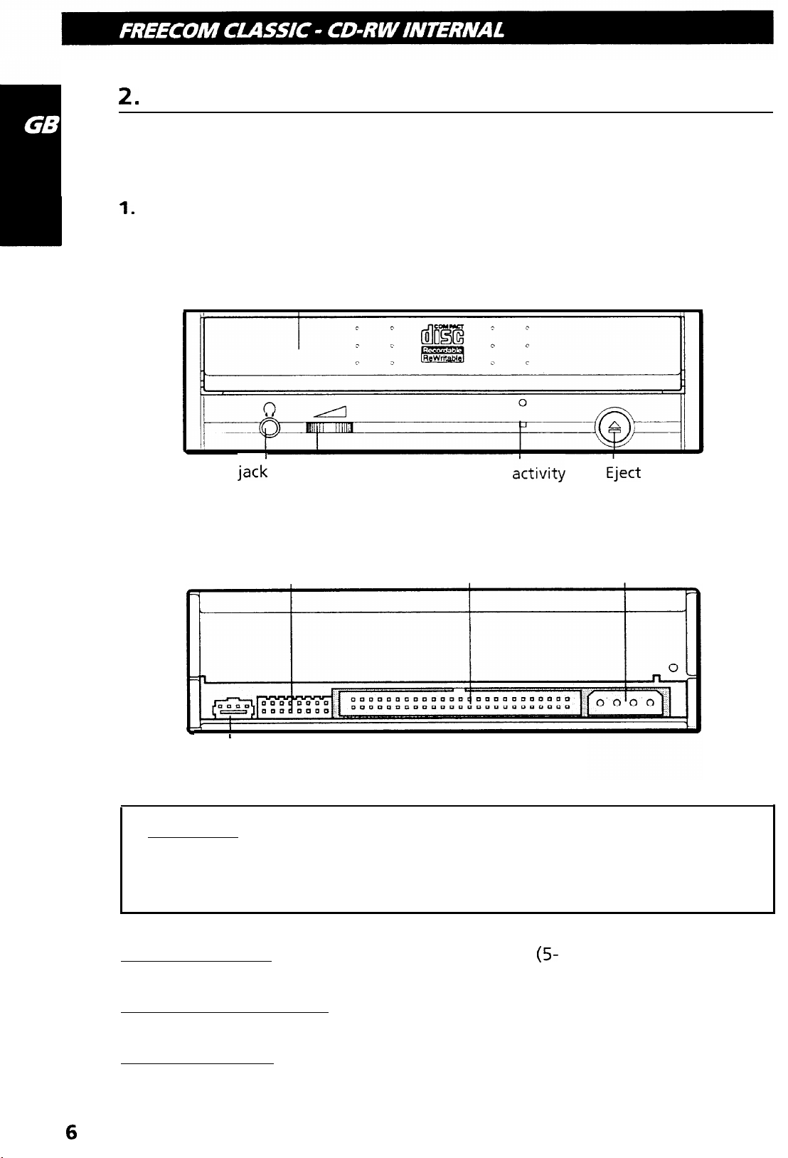
1.
Drive functions and settings
Front Panel
Disc-tray
Headphone
jack
Volume control
Drive
indicator
ictivity
iject
button
Rear panel
SCSI interface
Option connector
F
Audio’output
connector
I
connector
Power connector
Attantion! Connecting or disconnecting connectors while power is on
may result in a short circuit, causing damage to the equipment. When
connecting or disconnecting connectors, makesuretoturn off the power
beforehand.
Power Connector: Connects to the power supply
(5-
and 12-V DC) of the host
computer.
SCSI interface connector: Use a 50 pin double-end flat SCSI cable to connect to
the SCSI interface.
Option connector: Used when selecting the SCSI ID number. Don’t use jumpers
to change anything besides the SCSI ID, but keep the drive as initially set (no
jumper pins: ID 0) SCSI ID changes become valid after power is turned off, then
on again.
6
Page 9
Installing jumper pins besides the ones for SCSI ID settings may be the cause of
damage or abnormal drive operation.
2. Installing the Drive
2.1 Before Installation
Before installing the drive, please note the following points.
I your will need the following:
l
SCSI interface board and manual (The SCSI interface board is not included
with this product. You need to purchase it separately.)
l
Computer manual (You need the manual in order to find out location of the
bus slot for installing the SCSI interface board.)
l
A head screw driver of a suitable size to fit the securing screws for the drive
unit.
l
Turn off all peripheral appliances of the computer, and the computer itself,
and disconnect their power cords from the wall sockets.
l
Discharge any static electricity by touching the computer covers etc.
2.2 SCSI ID Settings
Before installation, set SCSI ID on the rear panel. A single SCSI interface can
connect with a maximum of seven peripheral SCSI devices. When using multiple
SCSI devices, a different SCSI must be set for each of them.
Attention! If two peripheral devices use the same SCSI ID number, it will cause
the host computer to operate abnormally or fail to start up.
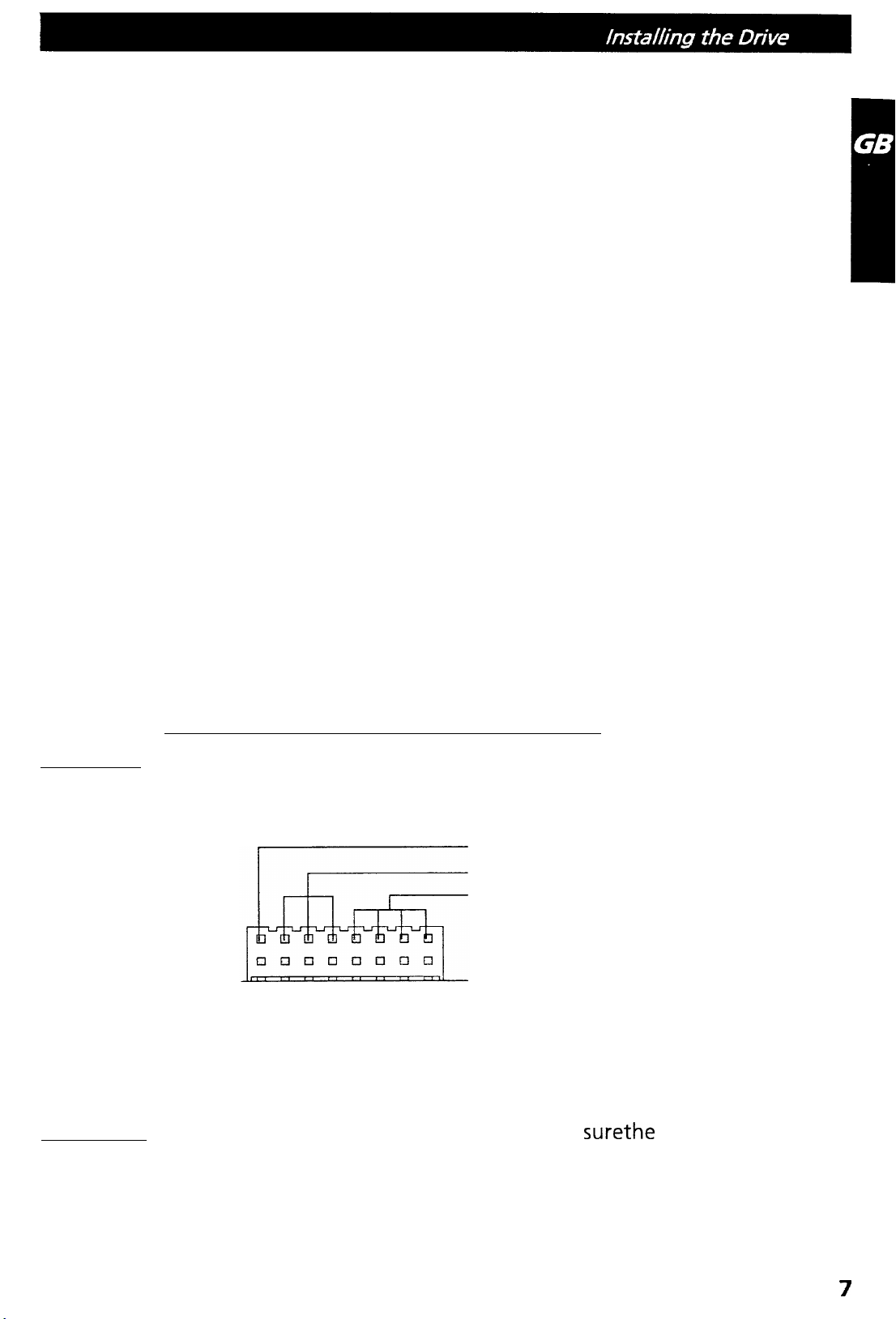
Terminator
SCSI ID
Reserve (Fixed OFF)
ON (When the jumper is attached)
OFF (When the jumper is removed)
Attention ! Before attaching or removing jumpers, make
rive is turned OFF.
surethe
power to the
7
Page 10
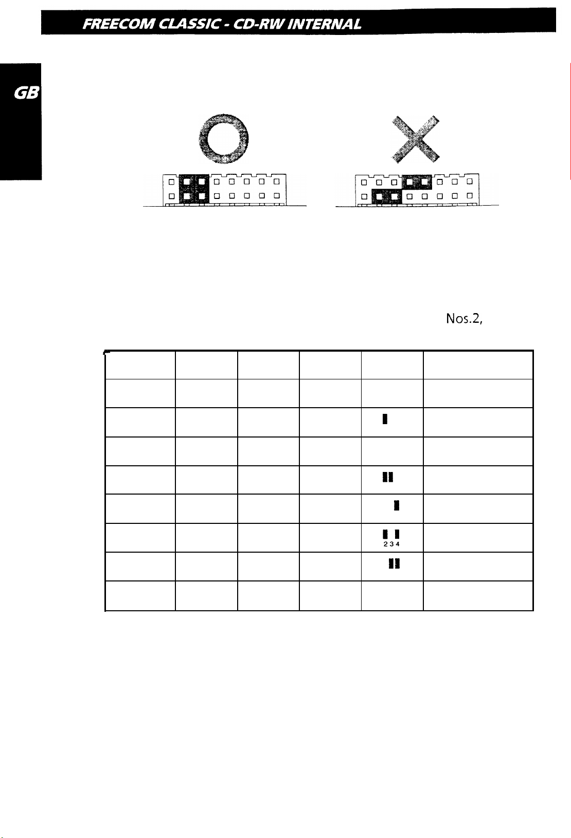
Attach the pins as shown in Figure 1. If t
in Figure 2, the drive may be damaged,
he pi
ns are attached sideways as shown
Figure 1.
Figure 2.
The pins besides pins 2-4 don’t have any function. lf jumpers are attached to
them, abnormal operation may result.
The SCSI ID number is decided by which of the jumper pins
Nos.2,
3 and 4 are
connected. Refer to the following table when changing the SCSI ID.
SCSI ID
0
1
2
3
4
Pin No.2
Pin No.3
OFF OFF
ON
OFF
ON
OFF
OFF
ON
ON
OFF
Pin No.4
OFF
OFF
OFF
OFF
ON
Jumper
234
I
234
I
234
II
234
I
234
Note
Initial
setting
5
6
7
ON
OFF
ON ON
OFF
ON
ON
ON
ON
!3!
13
234
111
234
SCSI
board
The initial setting for the SCSI interface board is generally set at SCSI ID 7.
Confirm the SCSI ID of the SCSI interface board before setting other numbers.
2.3 Terminator Setting
When no other SCSI peripheral devices besides the CD-RW drive are connected
to the host computer, a terminator must be attached to the drive. Also, when
multiple peripheral devices are connected, this drive needs a terminator if it is
the last in the line.
8
Page 11

Option
Connector
Terminator
ON : When the junmper is attached
OFF : When the jumper is removed
The terminator of this product can be set by installing (terminator: ON) or
removing (terminator: OFF) the jumper pin from the option connector. When
shipped, the jumper pin is installed (terminator: ON). Install or remove the pin
as required.
When one drive is connected
CD-RW drive (ON)
Terminator is attached (ON)
Terminator is not attached (OFF)
SCSI
n
cabel
SCSI
interface board (ON)
Host Computer
9
Page 12

When the drive and multiple peripheral devices are attached
When attaching terminators to other peripheral devices, use the terminators
that came with those devices.
CD-RW drive
(ON)
MO drive
(OFF)
Q
SCSI
caxrnal
Terminator is attached (ON)
Terminator is not attached (OFF)
H
Scanner (OFF)
SCSI interface board
2.4 Removing the Computer Cover
Make sure all peripheral devices of the computer and
the computer itself are turned off, and then remove
the cover. Refer to the manual for the computer for
details about removing the cover. There may be sharp
edges inside the computer so care must be taken to
avoid injury.
2.5 SCSI Interface Board Installation
SCSI-Interface board
Insert the SCSI interface board into the
specified bus (ISA, VL, PCI) slots for each
of them. Firmly push board until it is all
the way in and completely in contact
with its slot.
For a detailed explanation, refer to the
manuals for the SCSI interface board.
Host Computer
Page 13

2.6 Mounting the Drive
Remove the 5 inch drive bay panel from the computer. Refer to the manua
1.
for the computer for details.
le
Insert the drive unit into t
2.
bay. Do not apply excessive pressure to the
cables inside the computer.
Secure the drive with the screws provided. If there is not enough space
4.
behind the drive, connect the SCSI cables etc. before securing the drive.
2.7 Connecting the Power Connector
Connect the power cable from the computer’s power
supplyto
the socket on the
drive unit, fitting the connector snugly into the socket.
If there is no spare power cable available in the computer, you will have to
purchase a splitter cable of a suitable type.
11
Page 14

2.8 SCSI Interface and Sound Card Connection
Connect the SCSI interface board to the drive. If the computer is using a sound
card. The drive is connected to the sound card with an audio cable.
For a detailed explanation, refer to the manuals for the SCSI interface board and
the sound card.
Be
careful not to reverse the connectors when connecting the SCSI interface
board and the sound card to the dive.
r-
FREECOM internal
CD-RW
When L,R
Sound card
2.9 Replacing the Computer Cover
When the installation of the drive unit is complete, replace
the computer cover.
3. Device Drivers
SCSI interface board
connector
I-1
, /
,/’
/”
//
A’
,/
,/”
+-1
12
When using Windows
of any special device drivers are not required.
3.1 For Windows
In order to ensure normal drive operation, please check the following:
l The drive is displayed in [control panels]
ROM]
l 32-bit is displayed in [control panels]
95/98
95/98
or Window NT Workstation Ver. 4.0, the installation
Users
-
[system] - [device manager] -
-
[system] - [performance]
[CD-
Page 15

If the drive is not recogized by your computer, please check the folowing items:
l
If a indicator Q is displayed on the SCSI adapter in [control panels] - [system]
-[devices manager]-[SCSI controllers], you will need to contact your PC’s
manufacturer or the motherboard’s manufacturerand get the appropriate
SCSI controller driver.
3.2 For Windows NT Workstation Ver.4.0 Users
In order to ensure normal drive operation, please check the following:
l
The drive is dispayed on the SCSI controller in [control panels] - [SCSI adapter]
-[devices]
If the drive is not
l
If a indicator @ is displayed on the SCSI controller in [control panels] - [SCSI
recognized
byyourcomputer, please checkthefollowing items.
adapter] -[devices], you will need to contact your PC’s manufacturer or the
motherboard’s manufacturer and get the appropriate SCSI controller driver.
Internal IDE
ATAPI
CD-RW (Example 1)
1. Drive functions and settings
Front Panel
.
Headphone jack
Disc-tray
Volume control
e
c, 6EE
c
c li!fEEJ c :
c
‘,
:
0
Drive activity
indicator
.
Eject button
13
Page 16

Rear panel
Analog Audio Output
Connector
Digital Audio Output Connector
Power Connector: Connects to the power supply
Jumper Connector Power connector
IDE Interface Connector
(S-
and 12-V DC) of the host
computer.
Attantion! Be careful to connect with the proper polarity. Connecting the wrong
way may damage the system (and is not guaranteed).
IDE Interface Connector: Connect to the IDE (Integrated Device Electronics)
interface using a 40-pin flat IDE cable.
Attantion! Do not connect or disconnect the cable when the power is on, as this
could cause a short circuit and damage the system. Always turn the power OFF
when connecting or disconnecting the cable.
Jumper Connector: This jumper determines whether the drive is configured as
a master or slave. Changing the master-slave configuration takes effect after
power-on reset.
Analoq Audio Output Connector: Provides output to a sound card (analog
signal).
Diqital
Audio Output Connector: Not used.
2. Installing the Drive
2.1
Befor
Installation
Before installing the drive, please note the following points.
Your will need the following:
l
A head screw driver of a suitable size to fit the securing screws for the drive
unit.
14
0
The manual for the computer, so you can find out the positions for the IDE
controller.
0
Turn off all peripheral appliances of the computer, and the computer itself,
and disconnect their power cords from the wall sockets.
l
Discharge any static electricity by touching the computer covers etc.
Page 17

2.2 Jumper Set Up
Before installation, set the jumper on the jumper connector on the rear panel.
The drive can be connected as the Master or Slave on an
When several (up to four)
unique way. Specific knowledge of hardware and software is necessaryto install
the drive.
We cannot guaranty against direct or indirect damage resulting from improper
connections. Ask your supplier for details of the installation procedure.
Attantion! If two peripheral devices with the same settings are both connected
to the Primary or to the Secondary
or may malfunction, so careful attention is necessary.
CS: Cable Select
(GEL)
EIDE
devices are connected, each must be set in a
EIDE
bus, the host computer may fail to run,
EIDE
(ATAPI) interface.
Make sure that the host computer is turned OFF when connecting or removing
a jumper.
Connect the jumper in the vertical direction as shown in Figure 1. If connected
horizontally as shown in Figure 2, the drive may malfunction or be damaged.
Figure
(Master setting)
Attantion! Only one jumper should be installed on the jumper connector. If
more than ne jumper is installed, the drive may malfunction or be damaged.
1.
Figure 2.
15
Page 18

Master/Slave setting is determined by jumper installation on the Jumper Connector. The following table shows the possible jumper settings.
Name
MA
(Master)
SL
(Slave)
cs
(CaMe
Select) IDE interface
Function
Drive set as Master (factory default)
Drive set as Slave
_ri,
Drive mode set by CSEL on the host
A hard disk is normally installed as the Primary Master on the
interface. Other
EIDE
peripheral devices such as hard drives and CD-ROMs are
then set differently.
2.3 Removing the Computer Cover
EIDE (ATAPI)
Make sure all peripheral devices of the computer and the computer itself are
turned off, and then removethe cover.
Referto
the manual
forthe
computer for
details about removing the cover.
There may be sharp edges inside the computer so care must be taken to avoid
injury. (See fig.
,p.
10)
2.4 Mounting the Drive
1.
Remove the 5 inch drive bay panel from the computer. Refer to the manual
for the computer for details.
2. Insert the drive unit into the bay. Do not apply excessive pressure to the
cables inside the computer.
3.
Secure the drive with the screws provided. If there is not enough space
behind the drive, connect the IDE cables etc. before securing the drive.
(See fig.
,p.
1 I)
2.5 Connecting the Power Connector
16
Connect the power cable from the computer’s power supply to the socket on the
drive unit, fitting the connector snugly into the socket. If there is no spare power
cable available in the computer, you will have to purchase a splitter cable of a
suitable type. (See fig.
,p.
II)
Page 19

2.6 PC Connections
The CD-RW drive connects to the motherboard of the host computer using an
IDE interface cable. Both Primary and Secondaryconnectorsare usually provided
on the motherboard, which may be connected as follows:
Secondary
To Install as a Master Drive
To install the drive as a Master, the jumper can be left as supplied from the
factory.
1.
~~~
Master
(Booting
drive
hard
disk)
Primary connector
ary connector
17
Page 20

2.
Slave drive
Primary connector
Master
drive
Master drive
rive)
Secondary connector
3.
Master drive
(Booting hard disk)
Primary connector
Master drive
Secondary connector
18
Page 21

To Install as a Slave Drive
To install the drive as a Slave, change the jumper setting on the rear panel.
2.
3.
Master drive
(Booting hard disk)
Slave drive
(CD-RW drive)
Primary connector
Master drive
(Booting hard disk)
Master drive
(Other IDE drive)
Secondary connector
Master drive
drive)
Primary connector
\
Slave drive
Secondary connector
19
Page 22

2.7 Sound Card Connection
If the computer is using a sound card, The drive is connected to the sound card
with an audio cable. Make sure the connections are oriented so that L corre-
sponds to L and R to R.
Refer to the manual for the sound card for detailed information
It
,. ..-
_..... ::... 0003,
/
c
)+
:
-
I
+yI.\
____--
t
1
FREECOM
-1‘
CD-RW
internal
in the case of L-R
_II _
....
_..-
... ....
-._ .....I..
.......
...............
.
....................
,
..............
...........
-
....... .....
/
..........
.........
...*
..“.
.......
Primary or Secondary
Sound card
Motherboard
2.8 Replacing the Computer Cover
When the installation of the drive unit is complete, replace the computer cover.
(See Fig., p. 12)
20
3. Device Drivers
When using
Windows95/98
or Window NT Workstation Ver. 4.0, the installation
of any special device drivers are not required.
3.1 For Windows
95198
Users
In order to ensure normal drive operation, please check the following:
l
The drive is displayed in [control panels] - [system] - [device manager] ROM]
l 32-bit is displayed in [control panels]
If the drive is not
l If a indicator
-[devices manager]-[harddisk
recognized
Q
is displayed on the IDE controller in [control panels] - [system]
by your computer, pleasecheckthefollowing items:
controler],
-
[system] - [performance]
you will need to contact your PC’s
manufacturer or the motherboard’s manufacturer and get the appropriate
IDE controller driver.
[CD-
Page 23

3.2 For Windows NT Workstation Ver. 4.0 Users
In order to ensure normal drive operation, please check the following:
l
The drive is displayed on the IDE controller in [control panels] - [SCSI adapter]
-[devices]
If the drive is not
l
If a indicator Q is displayed on the IDE controller in [control panels] - [SCSI
recognized
by your computer, please check the following items.
adapter] -[devices], you will need to contact your PC’s manufacturer or the
motherboard’s manufacturer and get the appropriate IDE controller driver.
Internal IDE
ATAPI
CD-RW
(Example 2)
Front view
1.
Headphone Plug
2.
Headphone Volume
Control
3.
Write Indicator
4.
Disc Tray
5. Disc In/Active/Error indicator
6.
Open/Close Button
7.
Emergency Eject
1
2
7
34
5
6
Rear view
8. Audio Line out Connector
9.
Jumperblock
10.
IDE Connector
11
Most
DC Power Connector
8
9
10
11
AUDIO LINE OUT CONNECTOR:
1:
4 3
21
3:
Left
GND
2:
4:
GND
Right
JUMPERBLOCK: These jumpers are used to select Master/Slave mode and Cable
Select .
21
Page 24

IDE CONNECTOR: 40 pin IDE flatcable connector
HOST DC POWER CONNECTOR (type AMP 00641737-l)
m
4 3 21
l:+lZV
3: GND
2: GND
4:+5v
2. Installing the drive
1. Turn off your computer, monitor and other peripherals. To disconnect your
configuration completely from the mains, the mains plug has to be
discon-
netted.
2.
Remove the cover from your computer. Please consult the manuals that came
with your computer for specific details.
3. In order to mount the drive inside your PC (or other type of computer), locate
a free 5.25” bay and followthe instructions, as provided with your computer
systems, for installing the drive. When you are planning to use 8 cm discs your
drive should be mounted horizontaly or you should use an adapter (for
information contact your local supplier).
4. You have several possibilities to install your IDE data cable depending on
your existing configuration:
a) Hard-Disc connected as Master to Primary IDE Port,
CD-ROM connected as Master to Secundary IDE Port:
Connect FREECOM CD-RW as Slave to Secundary IDE Port.
\
I n
n n
PC Configuration
after Installation
r----.
I
Existing
PC Con@uration
I
h-l
-
_~-
--j
I
22
Page 25

b) Single Hard-disc connected as master to Primary IDE Port:
Connect FREECOM CD-RW as Master to Secundary Port.
c)
Hard-disc connected as Master to Primary IDE Port,
CD-ROM connected as Slave to Primary IDE Port:
Connect FREECOM CD-RW as Master to Secundary IDE Port.
\ -
I
l-7
I
II
II
CSM
S
\ ‘,
PC Configuration
after InstalJation
I
Primag~ fbt
_~ --~ --. ~~~~ ~
Secuncfary Port i CD-R\\
~~~ __
! MASTER SLAVE
____ L--~~-
/ Hxrc!-fhc CISR0.V
----
-
I
l’rilllal-y Pm
secuntl.lry f-‘cxt
-1
Existing
PC Configuration
i ~wmx 1 suvE
j
I
Iarcl-Ihsc. ) (.L)-fKl~~l
...I --~.-
i _
I -
Note: Installation A is preferred for systems with an IDE Hard-disc and CD-ROM.
Installation B is preferred for systems with only an IDE Hard-disk.
5.
Locate the free end of the IDE data cable and thread it out through the open
drive bay. Do the same with the power cable and the (optional) audio cable.
6.
Connect your (optional) audio cable, IDE data cable and the powercable into
the back of the FREECOM CD-RW. Make sure you correctly align pin 1 of the
cable to pin 1 of the connectors.
23
Page 26

7.
Insert
in the bag to secure the CD-RW into the bay.
8.
Replace the cover. Connect the mains plug of your configuration. When you
have successfully installed the drive and established all connections, it is now
time to switch on the PC. You are ready to run the
the software.
the FREECOM CD-RW into the drive bay. Using all the screws included
selftest
and then install
3. How to Use the Discs / Before Asking for Repairs
How to Use the Discs
Attantion! When using CD-ROM discs, CD-R discs or CD-RW discs, don’t attach
any stickers or labels to the discs. Using discs with them attached
read and write errors, but data on the disc may be lost due to damage to the disc
itself.
I.
Load the disc
not only causes
1. Press the eject button.
2.
Place the disc on the disc tray.
Note! When using a 120mm CD, place it in the large round depression. The face
with the label on it should be up. Never place both discs in the tray at the same
time.
This drive (SCSI
careful not to touch the recording surface of the disc.
3.
Load the disc by pressing the eject button or by lightly pushing in the disctray.
2. Disc ejection
1. Press the eject button.
2.
Slowly take the disc out of the disc tray.
3.
Press the eject button or push the disc tray and the tray will be brought back
into the drive.
After ejecting the disc, return the tray inside the unit quickly. When the tray is
in the ejected position, dust and other debris will enter, possibly causing read
errors, write errors, or drive failure.
CD-RW/IDE
ATAPI 4420) cannot be used with 80 mm CDs. Be
24
3. Emergency Eject
This drive has a function that allows the CD to be ejected manually if this
becomes necessary in an emergency such as failure of the drive or a power
outage. Follow the following procedures in such a case. Don’t use this feature
except in an emergency.
Page 27

1. Turn the power to OFF.
2. Poke a fine tipped object into the small hole above the eject button. The
front door pops open and the disk tray comes partway out.
3.
Pull the front door to open it all the way, then grip the disc tray between
thumb and forefinger and gently pull it straight out. This feature is a last
measure to be used only in an emergency. Using it excessively will cause
malfunction.
Note! If you cannot get a good grip on the disc tray with yourfingers, use a steel
binder clip or spring clamp to pull it out.
4. Using the Drive in a Vertical Position
The drive can be installed in a vertical position. If this is done, the tabs on the disk
tray will need to be rotated to stop the disk from falling out. with your finger,
rotate the tabs inwards until you hear a click, so they face the
center
of the tray.
The disk is inserted on the inside of these tabs.
Make sure the eject button is at the top of the unit when installing the unit in
a vertical position.
Before Asking for Repairs
Before thinking “Maybe it’s broken,” and ask
below just one more time.
The drive doesn’t have pa wer
l
Is the power supply cable from the host computer plugged in?
l
Are
DC5V
and
DCIZV
being correctly supplied to the drive?
The system doesn’t start
l Are the Primary and Secondary connections and the Master and Slave
settings correct?
l
Is the total length of the IDE cable 18 inches or less?
SCSI:
l
Is the SCSI ID number correctly set?
l
Has the SCSI interface board been correctly
l
Are the terminators correctly set or attached?
l
Is the total length of the SCSI cable within six meters?
ing for repairs, confirm the
recognized?
items
I D E-ATAPI:
l Are the Primary and Secondary connections and the Master and Slave
settings correct?
l
Is the total length of the IDE cable 18 inches or less?
25
Page 28

Cannot Read or Write Discs
E
l
Is the CD-RW device driver properly selected?
l
Is the condition of everything else in the system (CPU, hard disc, and others)
as it should be?
l
Does the CD-R or CD-RW disc have dirt or scratches? - Did a screen saver or
other application operate while writing to the disc?
l
Is there enough free space on the CD-R/RW disc?
l
Does writing fail even using the simulation test?
l
Is the disc loaded in the drive with the read/write surface facing the right
direction?
l Is the drive installed in the correct orientation?
l Was the drive or disc moved from a low temperature environ-ment to a high
temperature environment? (There is a possibility of condensation on the lens
in the drive or on the surface of the disc.)
FREECOM
hternef
Service
FREECOM Technologies makes the following service available in the Internet
under
l Online information about technical problems
l
l
http://www.freecom.com
current product information
Drivers, driver updates and software information
Supporf Hotline
The following hotlines are available if you still are unable to get your FREECOM
device to work properly after reading the manual and the suggestions for
correcting errors:
Great Britain:
USA:
Germany:
The Netherlands:
France:
+44-(0)1423
+I
-
781 275 57 42
520 185
+49-(0)30 611 299 28
+31 -
(0)70
301 30 20
+33-(0)134 047 205
26
If possible, try to call from a phone near your computer.
Please have the
l
the serial number of your FREECOM drive
l
information on the power supply
l
the version number of your operating system and the software you are
followinq
information on hand for your call:
Page 29

having problems with
l the precise error description or error message displayed
l
the name and the model of your computer and, in case it is needed, the
installed hardware
l
Is the problem reproduced every time?
l
Has this problem occurred before? If it is a new one, have you recently
changed your system configuration?
27
Page 30

FEDERAL COMMUNICATIONS COMMISSION
DECLARATION OF CONFORMITY
This equiqment has been tested and found to comply with the
limits for a Class B digital device, pursuant to part 15 of the FCC
Rules, and RS 210 Regulations (Canada). These limits are
designed to provide reasonable protection against harmful
interference in a residential area. This equipment generates,
uses, and can radiate radio frequency energy and if, not
installed and used in accordance with the instructions, may
cause harmful interference to radio communications. However,
there is no guarantee that interference will not occur in a
particular installation. if this equipment does cause harmful
interference to radio or television reception, which can be
determined by running the equipment off and on, the user is
encouraged to try to correct the interference by one or more
of the following measures:
l Reorient or relocate the receiving antenna.
l Increase separation between the equipment and receiver.
l Connect the equipment to an outlet on a circuit different
from that to which the receiver is connected.
l Consult the dealer or an experienced radio technician for
help.
Page 31

EC Declaration of Conformity,
D6claration
europeenne, EG-KonformitStserklSrung,
CE,
Declaracibn
de conformidad
EG Verklaring van Overeenkomstigheid, AB-Uygunluk
de
conformit& $I
Dichiarazione di
para
la
CE,
la directive
conformit&
Beyanl
FREECOM Technologies
ObentrautstraBe
72 l D-10963 Berlin
GmbH
Germany, Allemagne, Germania, Alemania, Duitsland
declares that the product, declare que le produit suivant,
dichiara
the il
prodotto,
declara
que el
producto,
. . . .
uruniin:
verklaart dat het produkt,
erklart, daR
das Produkt,
a$agrdaki
FREECOM internal CD-RW
with the model numbers,
contrassegnato dai
met de modelnummers, Model
codici
numeros
prodotto, con
de
modele,
10s numeros
Modellnummern,
numaralan:
de
modelo,
FC-RW-xxx-l-IDE, FC-RW-xxx-l SCSI
meets the essential protection requirements as set by the EMI guideline
89/336/EEC
following norms have been used for evaluating electromagnetic compatibility:
est
conforme
directive CEM
Etats membres de la CEE. Les normes suivantes ont
den wesentlichen Schutzanforderungen entspricht, die in der Richtlinie des Rates zur
elektromagnetische
hinsichtlich elektromagnetischer
of the council for standardizing legislation between member states. The
aux
exigences
89/336/CEE
Angleichung der Rechtsvorschriften der Mitgliedstaaten
des standards de protection electromagnetique fixes par la
du conseil pour la legislation
harmoniques
Vet-traglichkeit (89/336/EWG)
electromagnetiques
Vertrsglichkeit,
herangezogen:
sur
la standardisation au sein des
ete utilisees
festgelegt sind. Zur Beurteilung
wurden folgende
pour I’evaluation des
:
ijber
die
Normen
soddisfa i requisiti fondamentali di protezione previsti
EMI
stabilite
membri. Per la valutazione
cumple
del consejo
voldoet
de standaardisering van wetgeving binnen de lidstaten. De onderstaande
iiye iilkelerin
ba&rklrk
Low voltage guideline,
tensioni, Norma de baja tension, Richtlijn voor laagspanning,
dal comitato per la standardizzazione
delle
armoniche elettromagnetiche,
seguenti
con
las normas basicas
para
la adecuacion de la
las
siguientes
aan
de veiligheidseisen, zoals bepaald in EMI richtlijn
gebruikt voor de evaluatie van elektromagnetische verdraagbaarheid:
yasal kararnameleri
ile ilgili
yijnetmeli@nde (8913361EWG) belirtilen
beyan eder. Elektromanyetik
EN 55022: 1994 + Al: 1995 + A2:
EN 60950: 1992 + Al: 1993 + A2: 1993 + A3: 1995 + A4: 1997
normas para
Norme
de
protection
legislation
evaluar
arasrnda
iGin aqagtdaki
bas-voltage, Niederspannungsrichtlinie, direttiva per le basse
uyum
normlardan
norme:
establecidos por la directriz EMI
en
las
tolerancias electromagneticas:
saglanmasr iGin
bagr$rkl@ degerlendirmek
dalle
direttive
della
legislazione
sono
10s
estados miembros. Se han utilizado
89/336/EEC
kurulan konseyin elektromanyetik
korunma gereksinimlerine uygun
yararlanrlmrgtrr:
1997/
EN 50081-I: 1992
AlGak
89/336/EEC
all’interno
state utilizzate le
van de raad voor
Gerilim
per le
degli
89/336/EEC
normen
Yonetmeligi:
stati
zijn
oldugunu
Art-No. 13842 / Rev. 003
 Loading...