

Page 1

Internal drives - contents
Read the “Pre-Installation” and “Installing the tape drive” sections if you have to install or
replace your HP StorageWorks Ultriumtape drive. If you have purchased your tape drive preinstalled in a server, go directly to the operating and troubleshooting information commencing
on page 23.
Pre-Installation
Before you start page 3
Backup software and drivers page 5
Checking the SCSI connection page 7
Installing the tape drive
Step 1: Check the drive’s SCSI ID page 9
Step 2: Set the configuration switches (UNIX systems) page 11
Step 3: Prepare the mounting bay page 13
Step 4: Using the conversion kit (optional) page 15
Step 5: Attach mounting hardware page 17
Step 6: Attach power extension cable and install drive page 19
Step 7: Attach power and SCSI cables page 21
Step 8: Secure the drive page 23
Step 9: Verify installation page 25
Using the tape drive
Your DDS tape drive page 27
Use the correct media page 29
Optimizing performance page 31
Troubleshooting page 32
Problems with cartridges page 35
1
Page 2

Copyright © 2000-2003 by Hewlett-Packard Limited.
February 2003
This document has been produced for your tape drive or library vendor by Hewlett-Packard
The information contained in this document is subject to change without notice.
This document contains proprietary information which is protected by copyright. All rights are
reserved. No part of this document may be photocopied, reproduced or translated to another
language without the prior written consent of Hewlett-Packard Limited.
Hewlett-Packard shall not be liable for errors contained herein or for incidental or
consequential damages (including lost profits) in connection with the furnishing, performance,
or use of this material whether based on warranty, contract, or other legal theory.
Windows is a U.S. registered trademark of Microsoft Corp.
UNIX is a registered trademark of X/Open Company in the U.S. and other countries.
Product Details
Write your tape drive details here so you can find them easily if you need them. The model name is on
the front of the drive and the product and serial numbers are on a label on the bottom of the drive.
Model (type of drive):
Model (number):
Serial (number):
Date purchased/installed:
SCSI ID:
2
Page 3

Before you start
DDS models
This guide describes how to install and operate the following DDS internal tape drive models:
•DAT72
•DDS-4
Which operating systems are supported?
DDS drives can be connected to servers running under Windows®, NetWare, UNIX, Tru64,
Linux and .net. Refer to the manufacturer’s web site for more information.
How do I connect the drive to my server?
The following guidelines apply:
• For optimum performance the drive should be the only device on the SCSI bus.
• Always terminate the SCSI bus.
• Do not attach the drive to the same SCSI bus as your disk drive or to a RAID controller,
unless your configuration supports Tape-on-RAID.
You will need a properly installed and configured SCSI host bus adapter (HBA) or a built-in
SCSI controller on your server. Your tape drive is attached to the SCSI bus of the host server
via a spare connection on the internal SCSI ribbon cable. The cable should be compatible
with low voltage differential SCSI (LVDS) and it should have a spare 68-pin, high density
(HD), wide SCSI connector. See “Checking the SCSI connection” on page 7. The cable must
be terminated, see “Step 7: Attach power and SCSI cables” on page 21.
Why is the SCSI bus type important?
The SCSI bus type determines the speed at which data can be transferred between devices on
the bus and the maximum length of cable that can be used. The drives support a burst transfer
rate of 40 MB/sec. To benefit from this level of performance, it is important to ensure that the
drives are connected to a SCSI bus of a similar or higher specification. This means that you
need:
• An Ultra Wide, Ultra2 Wide, Ultra3 (160) or Ultra4 (320) SCSI bus. Ultra Wide SCSI
supports the maximum bus speed of 40 MB per second, Ultra2, Ultra3 or Ultra4 SCSI
exceeds this.
• LVD-rated SCSI cabling and terminators. The LVD interface enables the data to be
transferred at the drive's maximum rate.
If you attach the drive to a lower specification SCSI bus, it may still work but data will not be
transferred as quickly.
Note The drives are not compatible with high voltage differential (HVD) SCSI devices.
3
Page 4

What are the mounting requirements for the tape drive?
Mounting bay
You need one industry standard, 5¼-inch, half-height bay in which to install the DDS tape
drive. It can also be installed in a 3½-inch bay using the supplied conversion kit (see
page 15). Power requirements are:
Voltage Typical Current Maximum Current
5 V 3.5 A 4.0 A
12 V 0.3 A 1.7 A
Mounting hardware
For many servers, no mounting tray or rails are required. Devices simply slide into the server’s
chassis and are fixed with screws. Other servers have built-in trays or rails.
Some servers require a special mounting tray or rails to fix the drive into the empty bay. If this
is the case with your system, you will have to order these accessories from the server
manufacturer before you can install the tape drive. You may also be able to order mounting
hardware for some servers through your tape drive supplier.
Do I need additional items for installation?
• You may need mounting hardware. See “What are the mounting requirements for the tape
drive?” above.
• If you do not have a spare, suitably-rated SCSI connector on your server, you must install a
new HBA (also known as a SCSI card). This should be of an Ultra Wide or higher SCSI
specification. You will need to purchase and install the new HBA into an unused, 64-bit PCI
expansion slot within your server before installing your tape drive. (If you install in a 32-bit
PCI expansion slot, performance may be degraded.)
4
Page 5

Backup software and drivers
Backup software
For optimum performance it is important to use a backup application that is appropriate for
your system’s configuration. In a direct attach configuration, where the tape drive is attached
to a standalone server, you can use backup software that is designed for a single server
environment. In network configurations you will need backup software that supports enterprise
environments. HP, Veritas, Legato and Computer Associates all provide suitable products.
Further details about these and other products that may be appropriate can be found on the
supplier’s web site.
Make sure you have a backup application that supports DDS tape drives and download any
upgrades or patches, if required.
Drivers
Windows users
Before you install the tape drive, download the driver from the supplier’s web site. Refer to the
accompanying README file for specific installation instructions for Windows NT, Windows
98, Windows 2000, Windows ME and Windows XP drivers. This will tell you whether you
need to install the driver before or after installing the tape drive.
UNIX users
The recommended backup applications use the operating system’s standard, built-in device
drivers. To upgrade drivers we recommend that you patch to the latest version of the operating
system or configure device files.
IA64 users
If you are installing on IA64, check your supplier’s web site for the latest information on the
availability of backup application upgrades and drivers.
5
Page 6
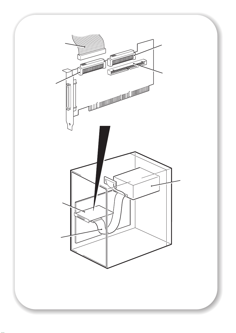
SCSI ribbon
cable
68-pin internal
LVD/SE connecto r
(Use this
connector)
68-pin internal
SE connector
(Do not use)
50-pin internal SE
connector
(Do not use)
The example shows an
Adaptec 29160 HBA
tape drive
SCSI HBA
SCSI ribbon
cable
Figure 1: checking the SCSI connection
6
Page 7
Checking the SCSI connection
Use the following questions to help you check your SCSI connection. As long as you have a
spare drive bay in your server you should have a spare connection on the internal SCSI bus.
You need to ensure it is the correct SCSI bus type. If you answer ‘Yes’ to all these questions,
you are ready to install your tape drive. If you answer ‘No’, you will probably need to
purchase and install additional items.
1 Have you checked the SCSI
bus type and SCSI IDs in use?
Yes
2 Is the SCSI bus type correct
for the SCSI specification of
the drive?
Yes
3 Will the drive be the only
device on the bus? This is the
recommended configuration.
Do not connect to a RAID
controller, unless your
configuration supports Tapeon-RAID, or the same SCSI
bus as your disk drive.
Yes
4 You are ready to install the
drive.
No
No
No
Check them now.
See table below. If the SCSI bus differs from
the recommended specification for the
drive, performance of either the drive or the
bus may be impaired. Consider replacing
your card with one of the recommended
HBAs.
If you have an Ultra HBA, performance may
be impaired. Consider installing (if you
have a spare PCI slot) or replacing your
card with an Ultra 2, Ultra 3 (160) or Ultra
4 (320) HBA.
SCSI Bus Type Supported
Ultra wide LVD Yes. This is a recommended configuration as long as the drive
is the only device on the SCSI bus.
Ultra 2 LVD, Ultra 3 (160)
LVD, Ultra 4 (320) LVD
Ultra wide, single-ended Yes. But this is not a recommended configuration as it will
Ultra narrow, single-ended Yes. But this is not recommended as it will severely restrict
High Voltage Differential No. The drive will not work and you may damage the drive or
table 1: supported SCSI bus types
Yes. These are recommended configurations, particularly if
there are several devices on the SCSI bus.
restrict performance.
performance and you will need a suitable cable or
adapter.
controller
7
Page 8
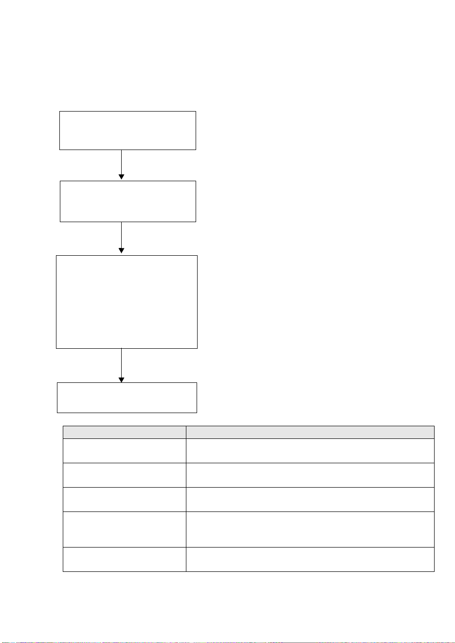
NCTP
2
8
4
1
NCTP
2
8
4
1
NCTP
2
8
4
1
3
611
(DEFAULT)
Figure 2: checking the SCSI ID
8
Page 9

Step 1: Check the drive’s SCSI ID
Your DDS drive is shipped with a default SCSI ID of 3. Each device on the SCSI bus must have
a unique SCSI ID number. The drive can be assigned any unused ID between 0 and 15. Do
not use SCSI ID 7, which is reserved for the SCSI controller. SCSI ID 0 is typically assigned to
the boot disk and should also not be used unless the tape drive is on a dedicated SCSI bus.
Caution Static electricity can damage electronic components. Always wear an antistatic wriststrap if
possible. If not, to equalize the electromagnetic charges, touch a bare metal part of the server
(such as the back plate) before you remove the tape drive from its bag.
1 Determine whether you need to change the SCSI ID from the default of 3.
2 Change the tape drive’s SCSI ID, if necessary.
The SCSI ID is set using jumpers on a set of pins at the rear of the drive, as shown in figure 2.
Use tweezers or small pliers to move the jumpers to the pattern corresponding to the ID you
want. Do not remove the TERM PWR jumper. It should always be set.
Spare jumpers will be attached to the drive.
9
Page 10
10
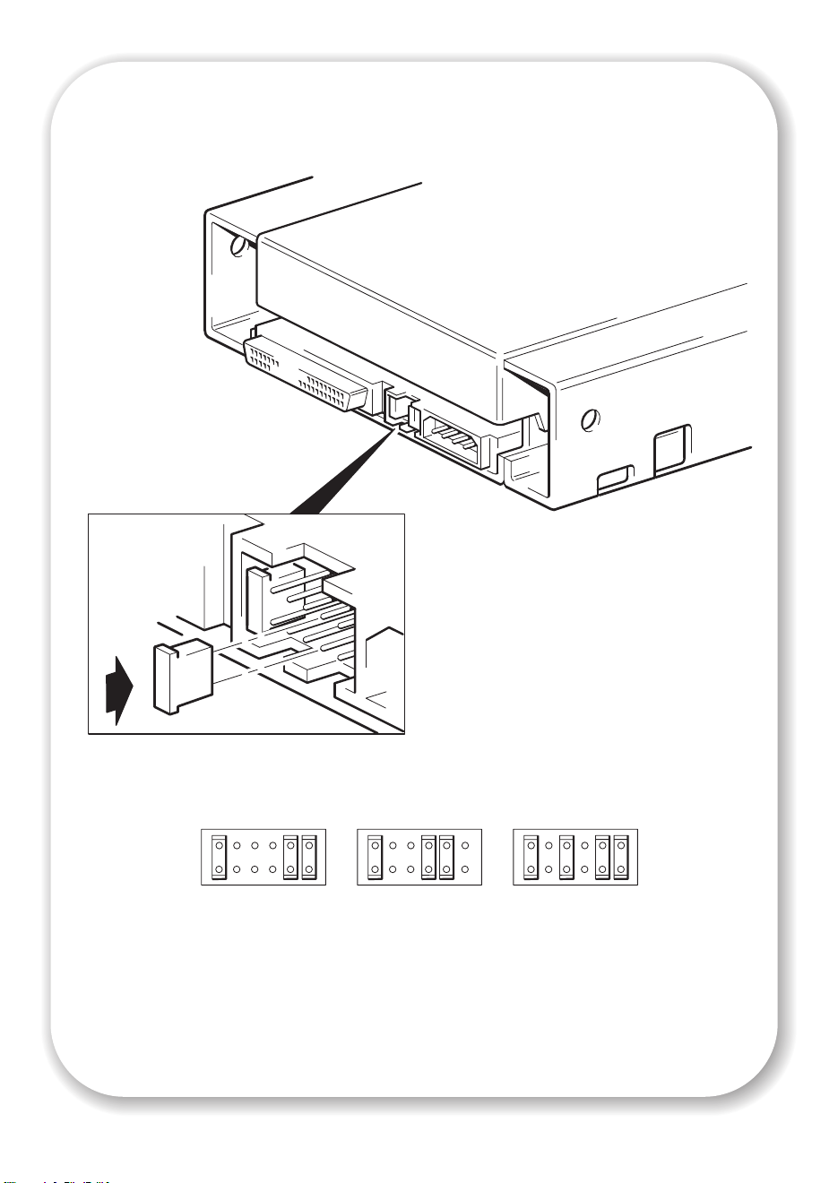
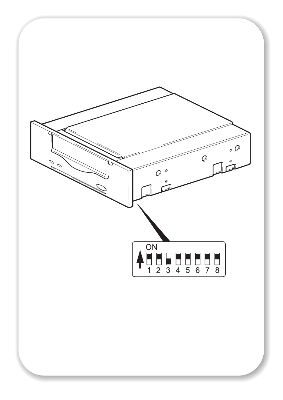
Figure 3: setting the UNIX configuration switches
Page 11

Step 2: Set the configuration switches (UNIX systems)
This section applies to UNIX systems only. If you are installing a tape drive on a PC system go
to “Step 3: Prepare the mounting bay” on page 13.
1 If you are installing a tape drive on a UNIX system, you may also need to change the
configuration switches, which are located on the underside of the drive.
The following table summarizes the typical switch settings for different types of server.
Switch Number
System Type 12345678
Default and most PC systems
HP Alpha systems
HP-UX systems
IBM RS/6000 systems
SCO/PC UNIX systems
Silicon Graphics systems
Sun systems
2 If your UNIX configuration requires it, change the configuration switches located on the
underside of the drive from the default settings shown in figure 3.
On On Off On On On On On
On On Off On On On On Off
On On Off On On On On On
On On Off On On Off Off On
On On Off On On On On On
On On Off On On Off Off On
On On On On On Off Off On
11
Page 12

Figure 4a: preparing mounting bay in a
typical HP NetServer server
Figure 4b: preparing mounting bay in a
typical HP ProLiant server
Figure 4c: preparing mounting bay in a
typical IBM server
12
Figure 4d: preparing mounting bay in a
typical Dell server
Page 13

Step 3: Prepare the mounting bay
Warning To avoid personal injury or damage to the server or tape drive, ensure that the server is
disconnected from the mains power supply while you install the drive.
Caution Static electricity can damage electronic components. Always wear an antistatic wriststrap if
one is available. If not, after you have disconnected power from the server and removed the
cover, touch a bare metal part of the chassis. Similarly, touch a bare metal part of the drive
before installing it.
1 Assemble the necessary tools and materials:
• Phillips screwdriver
• Flat-bladed screwdriver (if your server uses slotted screws)
• Torx screwdriver (if your server uses torx screws)
• Your server manuals (for reference during installation)
2 Perform a normal system shutdown and turn off the server and any connected peripherals.
3 Remove the cover and front panel from the server, as detailed in your server’s documentation.
As you work inside the server, you may have to disconnect the SCSI cable or power cable
from other devices to maneuver the new drive into place. If you have to do this, make a note
of their position and connections so you can put them back correctly later.
4 Remove the filler panel from a spare 5¼-inch (or 3½-inch) bay of your server, as described in
your server’s documentation. Keep any screws for use in step 8 on page 23.
If you will be installing the tape drive in a 3½-inch bay, you need to use the conversion kit as
described in step 4 on page 15, so that the drive will fit into your server. If your server has
5¼-inch bays, go to step 5 on page 17 now.
13
Page 14

14
Figure 5: using the conversion kit
Page 15

Step 4: Using the conversion kit (optional)
Only read this section if you are installing your drive in a 3½-inch bay. It describes how to
remove the 5¼-inch front panel from the tape drive and replace it with the 3½-inch front
panel.
If your server has 5¼-inch bays, go straight to step 5 on page 17 now.
1 Unscrew the four screws and remove the rails from the tape drive.
2 Use a screwdriver as illustrated in figure 5, to release each side of the 5¼-inch front panel from
the tape drive and remove it.
3 Fit the 3½-inch front panel, by aligning the side lugs and then push firmly until the panel clicks
into place.
15
Page 16

16
Figure 6: attaching mounting rails
Page 17

Step 5: Attach mounting hardware
For many servers, no tray or rails are required. Devices simply slide into the server’s chassis
and are fixed with screws. Other servers have built-in trays or rails.
If your server does not require special mounting hardware, proceed to “Step 6: Attach power
extension cable and install drive” on page 19 now.
If your server requires special rails or other hardware to install the tape drive in the empty
bay, mount them on the tape drive in this step. Mounting hardware for servers must be
ordered separately through your tape drive supplier or from the server manufacturer.
Please check your server documentation to ascertain the correct method of mounting, and to
check whether mounting hardware is provided with the server.
1 Attach the appropriate rails using the four screws supplied with the rail kit.
• If you are installing in a server that requires a tray, place the tape drive in the mounting tray
supplied.
• If you are installing in a server that requires mounting rails, fasten the rails to the tape drive,
as shown in figure 6. The rail design may not necessarily be as shown.
• Some servers have snap-on mounting rails attached to the filler panel. These can be removed
and attached to the tape drive with screws.
• If your server uses other mounting hardware, attach it to the tape drive as directed in your
server documentation.
17
Page 18

power cable
extension
18
Figure 7: installing the drive
Page 19

Step 6: Attach power extension cable and install drive
To connect power to your tape drive you may require a power cable extension. This may be
ordered through your tape drive supplier.
1 If required, attach the power cable extension to the power connector on the rear of the tape
drive, as shown in figure 7.
2 Slide the tape drive into the open bay, aligning the tray or rails with the slots in the bay, as
shown in figure 7.
If your server does not use mounting hardware, check that the holes in the chassis are aligned
with the holes in the side of the tape drive.
Do not secure the drive with screws at this point because you may have to move the drive to
get the cables into place.
Note Install a SCSI host adapter in the selected server or workstation now, if necessary. For
information on SCSI host requirements, see page 3.
19
Page 20

2
SCSI ribbon
cable
2
SCSI ribbon
cable, (correctly
terminated)
SCSI controll er
connection
1
power cable
tape drive
20
1
power cable
power supply
Figure 8: attaching power and SCSI cables
Page 21

Step 7: Attach power and SCSI cables
1 Attach a spare power cable from the server's internal power supply to the power connector,
as shown in figure 8, item 1.
2 Attach a spare connector on the server's built-in SCSI bus or HBA’s SCSI ribbon cable to the
SCSI connector of the drive, as shown in figure 8, item 2.
3 If the drive is the last device on the SCSI chain, make sure that the SCSI cable is terminated
correctly.
Where should the SCSI terminator be?
Termination must be present at two and ONLY two positions on the SCSI bus—at the
beginning of the SCSI bus and at the end of the SCSI bus. Termination is normally enabled
by default on the HBA and most internal SCSI cables have a terminator attached. This will
usually be a small, rectangular block of plastic attached to the cable end and marked ‘SCSI
Terminator’.
Therefore, assuming the HBA is the first device on the bus, you should check that the second
terminator is placed after the last device, as shown in figure 8, item 2.
21
Page 22

Figure 9a: securing drive to mounting hardware
22
Figure 9b: securing drive, no mounting hardware
Page 23

Step 8: Secure the drive
Mounting hardware used
1 Secure the tape drive into place. Use the screws you removed in “Step 3: Prepare the
mounting bay” on page 13 to fix the drive in place, as shown in figure 9a.
2 Replace the cover on the server.
No mounting hardware used
1 Secure the tape drive into place. Check that the holes in the chassis are aligned with the holes
in the sides of the drive and use the screws provided to secure the drive, as shown in Figure
9b.
2 Replace the cover on the server.
23
Page 24

cartridge door
arrow indicates
leading direction
Figure 10a: loading a cartridge
24
eject button
Figure 10b: unloading a cartridge
Page 25

Step 9: Verify installation
Once you have installed the drive hardware, verify that the tape drive is functioning properly
before you store your valuable data.
Check operation
Ensure that you have downloaded any drivers and upgrades necessary for your backup
application (see page 5).
1 Switch on the server. The tape drive will run its hardware self-test, which takes about 5
seconds. At the end of the hardware self-test, both front panel lights should be off. See “Your
DDS tape drive” on page 27 for more information about front panel lights.
2 Verify that the tape drive installation was successful.
Note If you encounter a problem during this verification procedure, turn to “Troubleshooting” on
page 32 for help in diagnosing and fixing the problem.
3 You are now ready to carry out a backup and restore test to check that the drive can write data
to tape. Use a blank cartridge, if possible.
To load a cartridge
1 Lift the cartridge door on the front of the tape drive and insert the cartridge into the slot in front
of the drive with the white arrow uppermost and facing the drive door. Apply gentle pressure
until the drive takes the cartridge and loads it. (See figure 10a.)
2 The Tape light flashes green while the drive performs its load sequence. When the cartridge is
loaded, the Tape light shows steady green.
To perform a backup and restore test
Refer to your backup application documentation for specific instructions.
1 Perform a trial backup of data to tape.
2 Perform a trial restore of data from tape.
To unload a cartridge
Caution Never try to remove a cartridge before it is fully ejected.
1 Press the Eject button on the front panel. (See figure 10b.)
2 The drive completes any task it is currently performing, winds the tape to the beginning, and
ejects the cartridge. The sequence will take about 25 seconds for a write-enabled cartridge
and 10 seconds for a write-protected cartridge.
25
Page 26

cartridge door
Eject buttonClean LEDTape LED
26
Figure 11: tape drive controls and indicators
Page 27

Your DDS tape drive
There are two LEDs and an eject cartridge button on the front panel of your tape drive. See
page 25 for more information about loading and unloading cartridges and page 35 for
information about forcing ejection.
Front panel LEDs
There are two LEDs, labeled Tape and Clean. (See figure 11.)
or
Tape LED
on off The cartridge is loaded and the drive is ready.
flashing
slowly
flashing
rapidly
off on This is the Error Condition Signal. DDS drives
off or
flashing
rapidly
Clean LED Meaning
off The cartridge is loading or unloading, or self-test is
in progress.
off The cartridge is loaded, activity is occurring.
perform a comprehensive self-test during power-up.
If a hard error causes the self-test to fail, the clean
light changes to steady amber.
flashing
slowly
This is the Media Caution Signal.
1 Wait for the current operation to finish, then
insert a different tape and repeat the operation that
was being performed.
2 If the media caution signal does not show this
time, it indicates that the original cartridge was
nearing the end of its useful life. Copy any data
you want to keep from the original tape onto a
new tape if possible, then discard the old tape.
3 If the media caution signal appears again with
the second tape, the tape heads need cleaning.
4 If the media caution signal appears after using
a cleaning cartridge, the cleaning cartridge has
probably expired and should be discarded.
27
Page 28

28
tab closed, cartridge
write-enabled
Figure 12: write-protecting cartridges
tab open, cartridge
write-protected
Page 29

Use the correct media
Data cartridges
For optimum performance and storage capacity, use tape cartridges that match your drive's
format, and normally use only one cartridge per day. Ideally, use DDS-4 cartridges with
DDS-4 tape drives and DAT 72 cartridges with DAT 72 tape drives.
Although DDS tape drives are fully backward compatible, old tape formats are more abrasive
than later generations and using older tape formats can reduce the life expectancy of the tape
drive. The compatibility between drive models and cartridges is summarized in the following
table. Shaded boxes show the recommended media for each tape drive.
DDS-1
90 meter
DDS-4
DAT 72
* Capacity assumes 2:1 compression.
table 2: data cartridge compatibility
Only rely on the best media to protect your valuable data. It is recommended that you only
use HP media with your tape drive.
read only read/write read/write 40 GB* not supported
not supported not supported read/write read/write 72 GB*
Write-protecting cartridges
If you want to protect the data on a cartridge from being altered or overwritten, you can writeprotect the cartridge. (See figure 12.)
Always remove the cartridge from the tape drive before you change the write protection.
• To write-protect a cartridge, slide the tab on the rear of the cartridge so that the recognition
hole is open.
• To write-enable a cartridge, slide the tab back so that the hole is closed.
Write-protection will not protect your cartridges against magnets (or bulk erasers).
Cleaning cartridges
We recommend weekly cleaning of the tape drive using a DDS cleaning cartridge. Do not use
swabs or other means of cleaning the heads. The cleaning cartridge uses a special tape to
clean the tape heads. A cleaning cartridge can only be used 50 times or as instructed on the
cartridge packaging. Always place a check mark in a box each time you use the cartridge to
clean the drive. Replace the cleaning cartridge when all the boxes are checked.
DDS-2
120 meter
DDS-3
125 meter
DDS-4
150 meter
DAT 72
170 meter
1 Insert a cleaning cartridge into the drive. The tape drive automatically loads the cartridge and
cleans the heads.
2 At the end of the cleaning cycle, the drive ejects the cartridge. The cleaning cycle takes
approximately 30-60 seconds.
DDS-4 drives: If the cleaning cartridge ejects in less than 20 seconds, it has probably expired.
In this case, discard the cleaning cartridge and repeat the operation with a new one.
29
Page 30

DAT 72 drives: If the cleaning cartridge is not ejected, it has probably expired. In this case,
press the Eject button, discard the cleaning cartridge and repeat the operation with a new
one.
3 Remove the cleaning cartridge from the drive.
The drive's TapeAlert feature will send a message to your backup application when the tape
heads need cleaning or a cleaning cartridge has expired.
Handling cartridges
• Do not touch the tape media.
• Do not attempt to clean the tape path or tape guides inside the cartridge.
• Do not leave cartridges in excessively dry or humid conditions. Do not leave cartridges in
direct sunlight or in places where magnetic fields are present (for example, under
telephones, next to monitors or near transformers).
• Do not drop cartridges or handle them roughly.
• Do not stick more than one label onto the cartridge label area; extra labels can cause the
cartridges to jam in the drive. Stick labels onto the label area only.
• See the insert included with the tape cartridge for storage conditions.
Getting the most out of cartridges and drives
• Use mostly the matching media type (DAT 72 media for DAT 72 tape drives, DDS-4 media
for DDS-4 tape drives).
• Use media for the recommended number of times (DAT 72 and DDS-4=100 full backups).
Overuse of the tape will cause it to degrade and possibly shed tape debris in the drive. Too
many new tapes can also cause wear of the drive as they are rougher than used ones.
• Do not verify (DDS does read-after-write checking automatically).
• Do not overload the server during backups. Maximize the transfer rate (run overnight with
no other processes) and use incremental backups if convenient.
• Do not overuse your tape drive—it is designed for approximately three hours of tape pulling
per day, not constant usage—and clean the drive regularly. See page 29.
• If you want to bulk erase cartridges, this should be done in a controlled environment. You
need to make sure there are no other cartridges with sensitive information on them anywhere
near the bulk eraser when in use. All data will be lost on cartridges that are bulk erased.
30
Page 31

Optimizing performance
Various factors can affect tape drive performance, particularly in a network environment or if
the drive is not on a dedicated SCSI bus.
If your tape drive is not performing as well as expected, consider the following points:
• Is the tape drive connected to a suitably-rated built-in SCSI bus or HBA, see “Why is the
SCSI bus type important?” on page 3. Suitably-rated means an Ultra Wide or higher SCSI
specification.
• Is the tape drive on a dedicated SCSI bus? For optimum performance, we recommend that
the tape drive is the only device on the SCSI bus. If it is not, ensure other devices are the
same SCSI specification as your tape drive model. If they are single-ended, the bus will
switch to single-ended mode with a lower transfer speed.
• Do not put tape drives and hard disks on the same SCSI bus.
• Is the SCSI bus terminated correctly? The last device on the SCSI bus must be terminated.
• Have you installed the correct device drivers for your operating system and backup
application? See “Backup software and drivers” on page 5.
• Are you backing up across a network? The network load may be affecting the speed of
transfer or your backup application may only be appropriate for a single-server
environment.
• Is the backup application writing buffers at the correct speed? You may need to tune the
transfer, buffer and block size settings to optimize the speed that the application writes data
to the tape drive. DDS tape drives have an internal buffer of 8 MB.
31
Page 32

Troubleshooting
The first step in problem-solving is establishing whether the problem lies with the cartridge, the
drive, the host server and its connections, or with the way the system is being operated.
Most modern SCSI host bus adapters locate and display attached devices when the system is
booting up. On Windows systems, if you swap or connect a product when your system is
running, you will need to reboot the system. IA32 systems also usually need to be rebooted.
UNIX systems may have pluggable drivers, which allow drives to be attached to a running
system and detected without rebooting.
If the device is not detected on boot up, there is probably a problem with the physical
hardware: cables, termination, connections, power or the host bus adapter itself. If the device
is displayed during boot up but cannot be found in the operating system, this is more likely to
be a software problem.
• If you encounter a problem during installation and need further clarification, refer to
“Problems encountered during installation” below.
• If a problem arises during testing after you have installed the drive, refer to the symptombased section “Testing after installation” on page 33.
• For information about cartridges, refer to “Problems with cartridges” on page 35.
Problems encountered during installation
Unpacking
Description Further information
Some parts appear to be missing or
damaged.
Contact your vendor if any parts need replacing.
32
The screws or mounting hardware are not suitable for the server
Description Further information
Additional parts may be required for
fitting the tape drive into the server.
The DDS internal tape drive will fit into most servers
without the need for additional hardware other
than that originally shipped with your system. If
additional parts are required, or the original parts
have been lost, contact your server vendor.
See “Step 5: Attach mounting hardware” on
page 17.
It is unclear which SCSI ID to use
Description Further information
It is uncertain which ID numbers are
available.
The DDS drive has its SCSI ID set to 3 by default.
This should be left unchanged unless this number is
already in use. Full instructions on how to change
the SCSI ID are given on page 9.
Page 33

How should the SCSI bus be terminated?
Description Further information
It is unclear if the bus is already
terminated or where an additional
terminator should be placed.
Typically, when connecting an internal drive to the
ribbon cable already inside your server then both
the host bus adapter and the end of the ribbon
cable will already be terminated and no further
action is required.
Is the correct SCSI host bus adapter installed?
Description Further information
The server already has a SCSI host bus
adapter but it is difficult to determine
what type it is.
The server may not have a SCSI host bus
adapter installed.
If your server is in its original configuration (no
SCSI adapters have been added or removed) then
contact your tape drive vendor to check the
compatibility of your system.
If not, you will need to purchase one. This may be
ordered through your tape drive supplier.
Do drivers need to be installed and, if so, which ones
Description Further information
It is unclear whether there is a need to
install drivers onto the system, and more
help is required.
The required drivers do not appear to be
available.
Typically, if you are using backup software that
states support for DDS drives, then all the required
drivers will be provided.
Future drivers will be provided via your tape drive
vendor when they become available.
Testing after installation
Remember that the system recognizes devices during boot-up. If you swap or connect a
product when your system is running, you will need to reboot the system. Rebooting the system
will reset devices and will often resolve problems. It is good practice to reboot every time you
add a driver or install firmware.
Caution Never power off the drive during a firmware upgrade.
The server does not reboot after installation
Possible reason Recommended action
You have connected the tape drive to an
existing SCSI bus that has other devices
connected to it and the SCSI address of
your DDS drive is probably identical to the
address used by another device.
You have installed an additional SCSI host
bus adapter and its resources are clashing
with an existing adapter.
You have disconnected the power or SCSI
cable from the server’s boot disk during
the drive installation process.
Make sure that each device on the SCSI bus has a
unique ID.
We recommend that the DDS tape drive is
connected to a dedicated host bus adapter. Do
not connect the drive to a disk RAID controller
unless your configuration supports Tape-on-RAID.
Remove the new host bus adapter and check the
server documentation.
Check that the cables to all devices are firmly
connected.
33
Page 34

The server boots but does not recognize the tape drive
Possible reason Recommended action
The power or SCSI cable is not connected
properly.
The SCSI bus is not terminated correctly. Check that the SCSI bus is actively terminated.
The tape drive’s SCSI ID address is not
unique.
Check that the cables to the tape drive are firmly
connected. Ensure that the SCSI cable does not
have any bent pins. Replace, if necessary.
(Refer also to the documentation for your SCSI
controller and any other SCSI devices you may
have.)
Make sure that each device connected to the SCSI
controller has a unique SCSI ID. Remember that 7
is normally reserved for the host bus adapter.
The application does not recognize the tape drive
Possible reason Recommended action
The application does not support the tape
drive.
Some applications require drivers to be
loaded.
Refer to your tape vendor for details of backup
applications that support the DDS tape drive.
Load any service packs as necessary.
Check that the correct SCSI and tape drive drivers
are installed. Consult the backup application’s
installation notes for details.
The drive does not work
Possible reason Recommended action
If the drive does not power up, the power
cable may not be connected to the drive
properly.
If the self-test fails, there may be a
hardware or firmware failure.
There is a hard error on the drive. The Media Caution (Clean) LED shows steady
Check the power cable connection and try
another cable if necessary. If the drive still does
not power up, call for service.
If there is a cartridge in the drive, remove it. Power
down the drive and power it up again. If the selftest still fails, call for service.
amber. Try powering the system off and then on
again. If the error condition signal still shows, call
for service.
34
Page 35

Problems with cartridges
If you experience any problems using branded cartridges, check:
• The cartridge case is intact and that it contains no splits, cracks or damage.
• The cartridge has been stored at the correct temperature and humidity. This prevents
condensation. See the insert included with the tape cartridge for storage conditions.
• The write-protect switch is fully operational. It should move from side to side with a positive
click.
The cartridge is jammed
If the cartridge is jammed or the backup application is unable to eject it, you can force eject
the cartridge. Once the cartridge is successfully ejected, it is good practise to upgrade the
firmware. If the failure occurs regularly, contact your tape drive supplier.
1 Either press and hold the Eject button on the front of the tape drive for at least 15 seconds.
Or press the Eject button three times within 5 minutes.
2 Wait for the cartridge to be ejected. The drive waits until 35 seconds have passed from the
time of the first press to give the normal eject procedure a chance to proceed. After this period,
it immediately releases the tape and ejects the cartridge, regardless of what operation it was
performing. It is important that you allow sufficient time for the drive to complete this process.
If you interrupt it, you may damage the media or the tape drive. The drive is then reset as
though you had turned the power off and then on again.
You may lose data if you force eject a cartridge. The tape may also become unreadable
because an EOD (End of Data) mark may not be properly written.
3 If the cartridge is still jammed, the tape drive has failed. Contact your tape drive supplier.
The drive will not accept the cartridge (or ejects it immediately)
The cartridge may have been damaged, for example dropped, or the drive may have a fault.
If it is a cleaning cartridge, it has probably expired and should be discarded immediately. For
data cartridges:
1 Check that the drive has power (the Tape LED is on).
2 Check that you are using the correct media for the tape drive, see page 29.
3 Make sure that you have loaded the cartridge with the correct orientation (see “To load a
cartridge” on page 25).
4 Check for damage to your media and discard it if it is damaged.
5 Use a new or known, good piece of media and see if it loads. If it does, the original cartridge
is faulty and should be discarded.
35
Page 36

6 Check if another DDS drive of the same model will accept the cartridge. If it does, the original
drive may be faulty. Before contacting your tape drive supplier, please check that the tape drive
is responding and that it can be seen on the SCSI bus.
36
 Loading...