

Page 1

Document Number:
XE-FTC2PM-R0A
FTC200 Rev151207
PORTABLE SAMPLING
FLOW & PRESSURE METER
MODEL FTC200
FIRE RESEARCH CORPORATION
www.reresearch.com
26 Southern Blvd., Nesconset, NY 11767
TEL 631.724.8888 FAX 631.360.9727 TOLL FREE 1.800.645.0074
1
Page 2

FTC200 Rev151207
CONTENTS
Table of Contents
CONTENTS ................................................................................................................ 2
List of Tables.......................................................................................................... 3
List of Figures ........................................................................................................ 3
INTRODUCTION ...................................................................................................... 4
Overview ................................................................................................................ 4
Features .................................................................................................................. 4
SYSTEM COMPONENTS ......................................................................................... 5
Panel Diagram (Display Module) .......................................................................... 5
Panel Controls and Ports Summary: ...................................................................... 6
FIELD OPERATION .................................................................................................. 9
Battery Management System ................................................................................ 9
Making Connections ............................................................................................ 10
Channels .............................................................................................................. 10
Recording ............................................................................................................. 11
Data Management ................................................................................................ 12
PROGRAMMING .................................................................................................... 14
Enter Password for Program Access .................................................................... 14
Operator P-100 Codes .......................................................................................... 16
Set Date and Time (codes P107 and P108) .......................................................... 17
Firmware Update (code P109) ............................................................................. 18
Flow Calibration (code P111) .............................................................................. 19
Pressure Calibration (code P112) ......................................................................... 21
Error Codes and Fault Warnings Troubleshooting Table ..................................... 22
PARTS LIST ............................................................................................................. 23
Specications ....................................................................................................... 24
Flow Sensor ......................................................................................................... 25
Pressure Sensor .................................................................................................... 26
FLOW SENSOR MAINTENANCE ......................................................................... 28
2
Page 3

List of Tables
Table 1. Program Functions P-Codes Quick Reference ........................................... 16
Table 2. Error Codes and Fault Warnings Troubleshooting ..................................... 22
Table 3. Parts List .................................................................................................... 23
Table 4. Pressure Sensor Output Voltage ................................................................. 26
FTC200 Rev151207
List of Figures
Figure 1. Controls and Indicators ............................................................................... 5
Figure 2. Sample File Format .................................................................................. 12
Figure 3. Flow Sensor Wiring .................................................................................. 25
Figure 4. Pressure Sensor Wiring ............................................................................. 27
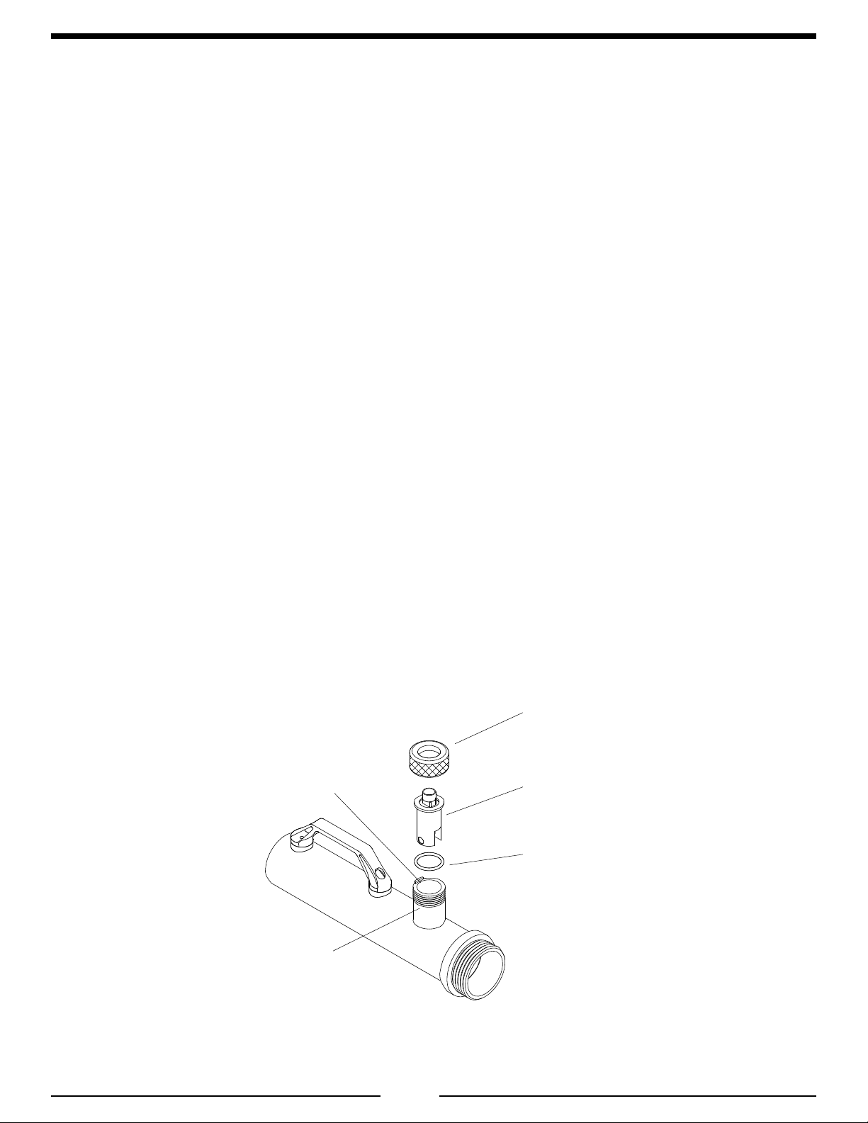
Figure 5. Flow Sensor Maintenance ........................................................................ 28
3
Page 4

FTC200 Rev151207
INTRODUCTION
Overview
The DataTron FTC200 Portable Flow Meter is an easy-to-use 4-channel portable sampling ow and pressure meter.
It can record these values over time internally to automate the process of testing ow and pressure. This enables the
operator to press a button and use the same portable tester with different size ow tubes. It provides connections for up
to four ow tubes, displays pressure and ow readings for any or all four of the tubes simultaneously. Up to four tubes
of different pipe sizes can be used at the same time. This device can be operated in either a Manual mode or Automatic
mode. Using the Automatic mode will automate the process of testing ow and pressure.
The FTC200 Portable Flow Meter uses paddlewheel type ow sensors, and pressure sensors that are mounted in
each of the four ow tubes. The paddlewheels contain a unique ID chip with memory storage to hold the calibration data
for each of the four ow tubes. Flow rate information is provided from the paddlewheel ow sensors mounted in the ow
tubes. This information is processed and shown on the digital display as ow rate. The user can retrieve sampled data
with either a USB ash drive or from a computer with a USB cable.
The FTC200 has a 4-digit Red LED display with daylight bright digits 0.39 inch (10 mm) high for PRESSURE
readings, a 5-digit Blue LED display for FLOW, and a 2-digit LED display for both TIME and COUNTS. The owmeter
electronics are self contained; program features are accessed via push buttons on the front of the module. Input connections
and cables are also accessible on the front panel.
The FTC200 can be powered by an external power supply (provided), or an external 10-30V DC source (with
supplied battery jumper cable or cigarette lighter plug). To charge the internal battery, plug the cable into the POWER
input on the front panel , connect the POWER SUPPLY to a 120/240 VAC electrical outlet and place the power switch
in the ON/CHARGE position. If the batteries are depleted, the unit can be used while the batteries are being charged.
Features
Measures Flow in GPM/LPM using paddlewheel sensors
Measures Pressure in PSI/kPa/BAR using calibrated sensors
Monitors up to 4 channels individually for ow and pressure
Manual snap-shot recording of data for all 4 channels
Automatic Mode records a maximum of 99 events
Multiple Flow Rate Calibration Points
Uses Multiple Diameter Flow Tubes (Please see Specications on page 24.)
Summing Flow Function
Paddlewheels connected to each of the four ow tubes store the calibration memory data
Data Captured can be retrieved through a USB ash drive (via USB port “A”) or via USB Cable connected to a
computer (mini “B” port)
4
Page 5

SYSTEM COMPONENTS
Panel Diagram (Display Module)
FTC200 Rev151207
Figure 1. Controls and Indicators
5
Page 6

FTC200 Rev151207
Panel Controls and Ports Summary:
• CHANNEL CONNECTORS 1 THROUGH 4
• BUTTONS 1 THROUGH 4 – CHANNEL SELECT
• LED 1 THROUGH 4, GREEN – CHANNEL SELECTED INDICATORS
◦ Press a button to read the channel’s Flow & Pressure.
• DISPLAY- 4-DIGIT RED–PRESSURE
◦ The selected channel’s pressure reading.
• DISPLAY 5-DIGIT BLUE–FLOW
• BUTTON–SUM
• LED, RED–SUM INDICATOR
◦ The selected channel’s ow reading.
◦ Press to sum the ow of all 4 channels together.
• BUTTON–MENU
• BUTTON–SELECT
• BUTTON - UP
• BUTTON - DOWN
◦ Use these to edit various setups and modes.
• DISPLAY 2-DIGIT–TIME
• DISPLAY 2-DIGIT–COUNTS
◦ Set recording parameters quickly & easily
• BUTTON–AUTO
◦ Press to automatically sample all parameters on a regular basis.
• BUTTON–MANUAL
◦ Press to take a single snap-shot.
• LED RED–RECORDING
◦ Unit is in a recording session.
• CONNECTOR – MEMORY (USB-A, HOST)
• LED RED – “BUSY” (MEMORY)
◦ Insert a USB ash drive compliant with USB 2.0 and formatted to the standard FAT32 le system to
obtain your recorded data.
• CONNECTOR - TO COMPUTER
• LED RED – “BUSY” (COMPUTER MINI_AB DEVICE)
◦ Connect a USB cable to your computer to easily transfer data, just like a memory stick would work.
• LEDs – % STATE OF CHARGE (SOC)
• BUTTON PWR (POWER ON/CHARGE/OFF)
• CONNECTOR – PWR IN (POWER INPUT)
◦ Monitor and control the unit’s power easily – everything is automatic.
6
Page 7

FTC200 Rev151207
Case
The DataTron FTC200 4-channel portable sampling ow and pressure meter is mounted inside of a resilient,
high impact, structural copolymer case. The case is watertight, airtight, dustproof, chemical resistant and corrosionproof , and has an automatic purge valve for quick equalization after changes in atmospheric pressure. All controls
and indicators are located on the front panel. (Refer to Controls and Indicators.)
Internal Battery
The DataTron is powered by a rechargeable battery and must be charged regularly. A fully charged battery
will provide approximately 8 hours of operating time. When the tester is not in use, the ON/OFF switch should
be left in the OFF position. The 0% RED LED indicator will illuminate when the battery needs to be charged.
External Power Supply
A 120/240 VAC power supply is provided to power the DataTron. To charge the internal battery, switch the
power off, then plug the cable into the POWER input on the front panel and connect the other end to a standard AC
electrical outlet. The power supply can be used internationally and the wall adapter can be changed as necessary.
The battery must be charged with the ON/OFF switch in the ON position.
Accessory Adapter
A 12/24 VDC power source (car or truck battery) can also be used to power and charge the DataTron. Plug
the provided DC Power Cable into the POWER input on the front panel and connect the other end to a DC source.
Jumper Cable
The jumper cable is provided to connect with any external 12/24 VDC power source. This cable allows for
charging with a standard vehicle battery and ends with red and black alligator clips, which are attached to the
vehicle battery.
NOTE: When external power sources are not in use, protect the 2-pin POWER port with seal plug.
Sensor Cable
Cables for each of the Four Flow Tubes with 6-pin Deutsch Connectors are available for the four ow pressure
channels on the DataTron. Use the 3-pin connector on the cable marked for the ow sensor to plug into the ow
sensor, and use the other 3-pin connector on the cable marked for the pressure sensor to plug into the pressure
sensor. When not in use, the connectors should be covered with the seal plugs, which are provided as a standard part.
Flow Sensor
The ow sensor is provided as a paddlewheel type of device, which should be properly mounted inside of
the ow tube. (See specications section for more details for installation.) This sensor converts the rotations from
the paddlewheel into electrical pulses of a proportional frequency. This data is processed and shown on the FLOW
display.
Pressure Sensor
The pressure sensor is provided and converts pressure for each channel into DC voltage, which is then
processed and shown on the PRESSURE display.
7
Page 8

FTC200 Rev151207
Flow Tubes
Each ow tube will have a mount for a paddlewheel ow sensor and pressure sensor. They must meet all specications
required to ensure proper operation with the ow channels. Refer to the Specications section for details. Caution: Care
should be taken not to drop the ow tubes. Dropping the ow tubes could result in damage the exterior of the tubes or the
ow and pressure sensors.
USB Flash Drive
Use a USB ash drive compliant with USB 2.0 and formatted to the standard FAT32 le system for data
retrieval by inserting into the MEMORY input on the right side of the front panel of the DataTron. Press the
MEMORY button to transfer the data. (See the Data Management section for further information.)
USB Cable
A USB cable is provided and connects into the TO COMPUTER input on the front of the right side of
the DataTron, which then connects also into the USB port on your computer. Once the USB cable is plugged
into the port on the DataTron and connected to the computer, and the COMPUTER button is pressed, the
DataTron will appear as an external drive.
8
Page 9

FTC200 Rev151207
FIELD OPERATION
Battery Management System
Note: The DataTron may be used while it is charging, and the length of time for the battery to fully
charge will not be affected. The charge time is the same when it is in stand-by, or not being used.
Note: Please be certain to turn the power to the off position before changing power sources.
Note: If the device is left on and not being used for certain period of time, it will go into ship and
store mode (powers down to preserve battery life).
ON/CHARGE
Turning on the unit:
1. Move the toggle ON/OFF switch to the ON/CHARGE position.
2. The PRESSURE display shows the time and date briey, while FLOW displays the current rmware revision.
3. Switch to the ON/CHARGE position to charge the DataTron.
4. Keep the switch in the OFF position to fully disconnect the DataTron for shipment.
5. Always keep the switch in the OFF position when not in use to prevent the internal battery from draining,
or to help preserve the life of the battery. When switched to the OFF position, the battery is disconnected.
Internal Battery
The battery used in the DataTron is a maintenance free, LiFe PO4 (non-toxic, recyclable, lead-free). When
the battery is almost depleted, use either the external power supply (for a wall outlet), accessory adapter or jumper
cable to charge the DataTron. The unit must be in the ON/CHARGE position to charge.
State of Charge Indicator
Battery charge level is displayed as either 0%, 25%, 50%, 75% or 100%, and the corresponding LED next to
the battery level percentage will light up.
External Power Supply
The universal external power supply with input voltage range of 100-240 VAC 50/60 Hz is provided with a
removable plug, and can be replaced with the type needed for the country where the product will be used. Press
the button on the back to release the clip and slide the connector on for your country. The power supply can be
plugged into the wall and plug the other end into the POWER input on the DataTron. The power switch must
be in the ON/CHARGE position to charge.
Accessory Adapter
Plug the provided DC Power Cable into the POWER input on the front panel and connect the other end to
a DC source.
Jumper Cable
Plug the jumper cable into the POWER input on the front panel of the DataTron. The jumper cable is provided
to connect to any external 12/24 VDC power source (such as a vehicle battery).
9
Page 10

FTC200 Rev151207
Making Connections
Before taking measurements, make sure the 6-pin Deutsch connector is connected to the ow and pressure
channel that will be measured.
1. Plug the pressure sensor cable ending in a 6-pin Deutsch connector (part no. XE- FTIPFPM-C20A) into the
ow and pressure channel until the tab rmly locks into position in the port on the DataTron for the selected
channel (1 through 4). (An audible "click" will be heard once it is plugged in completely.)
2. Plug the other end of the IPF-PM pressure sensor cable (shaped like the letter "Y") into the pressure transducer
and ow sensor.
3. One part of the cable will be labeled as "Flow Sensor" (with a blue heat shrink); plug this 3-pin connector into
the ow sensor. This will lock into position with the tab on the connector.
4. The other half of the cable with the other 3-pin connector (with a red heat shrink) is labeled as "Discharge Sensor";
this 3-pin connector plugs into the pressure sensor. This also locks into position with the tab on the connector.
Channels
Reading Flow (Flow Tube Control)
1. To verify pipe size, press and hold any ow channel button (1,2, 3 or 4), and before the button is released the
FLOW display shows the pipe size for that channel in either millimeters or inches. After letting go of the button,
the pressure and ow value readings for that channel are shown in the corresponding PRESSURE and FLOW
displays.
2. This action can be repeated for channels 1 through 4 to conrm the pipe size for each of the pipes connected to
their respective channel.
Flow Sum Mode
1. SUM button—Use to display the sum of all 4 ow channels. Press and release the SUM button (labeled
as " FLOW/SUM" ); the sum LED light turns on. In the FLOW display, the sum of the ow for all
4 channels will be shown.
2. To exit sum mode, press the SUM button again, or press one of the ow channel buttons. The LED shuts
off , the device goes back to the selected channel or the one that was previously in use prior to activating
SUM mode. FLOW and PRESSURE values are displayed for that channel.
NOTE: The PRESSURE display will be blank during the sum mode.
Reading Pressure
To read pressure, press and release any of the four channel buttons. Pressure for the selected channel
will show in the PRESSURE display (as stated above in "Reading Flow").
10
Page 11

FTC200 Rev151207
Recording
The DataTron can be programmed to automatically record the desired count of measurements (from 01-99)
separated by the time interval for each count in minutes.
Manual Mode
1. Manual Sample - press "MANUAL" to record pressure and ow as a snap-shot of the data recorded into
the internal memory. The snap-shot recording in Manual mode will record the set up, date, time and sum
for that specic event.
2. At the start of the manual recording session, the LED light goes on momentarily, and then shuts off when
the session is nished.
Set Up for Automatic Mode
1. Before the recording session begins, rst press the SELECT button.
2. The TIME display will start blinking, which indicates this is the active option. (Each menu option will
ash when you are on the active option.) Then adjust the value for time by pressing the UP and
DOWN arrow buttons to the right of the TIME and COUNTS displays. Adjust the time in minutes.
3. When the value for the time has been set to the desired number, press the SELECT button again. The COUNTS
display will start blinking. The number of preset counts are adjusted with the and DOWN arrow
buttons, as the time value was just adjusted. When the desired number has been reached for COUNTS, press
the SELECT button. When you are ready to begin recording, press the AUTO button to begin recording in
Automatic Mode. (The rst sample is taken immediately upon pressing the AUTO button, and the number
of COUNTS will decrease by 1.)
NOTE: Once the values have been set, they will be saved in memory until the next time it is turned back
on. The back up memory retains the values that were preset last (even when the unit is powered off).
NOTE: TIME - This displays the length of the interval (in minutes) between each recorded sample.
COUNTS - This displays the number of samples to be recorded.
For example: if the number of counts is set at 10, and the time interval is set for ve (5), this equals a
45 minute recording session. The rst sample is taken as the AUTO button is pressed, and the COUNTS
value decreases by one (1). In this case, the remaining number of COUNTS will drop down to nine (9),
after the rst sample is taken.
(TIME or COUNTS can be any value from 01-99.)
Automatic Mode—Starting the Recording Session
1. Be sure to rst go through the Set Up process as described above.
2. After pressing AUTO button, the recording session starts and the LED lights up under RECORDING.
3. Immediately after the AUTO button has been pressed, the rst snap-shot sample is taken. The number
of counts will decrease by one from the rst snap-shot recording of data.
4. After each time interval has passed, the number of preset counts will continue to decrease by one count
until the count value reaches zero. Once the number of counts reaches zero, the automatic recording
session has ended, and the RECORDING light will shut off.
5. To disable/cancel Automatic mode, press and hold the AUTO button for approximately 2 seconds.
(The LED light under the RECORDING light will shut off and the COUNTS will be at 0 when the session
has been cancelled.) Before exiting, one nal data sample is taken and then the sample le is closed.
11
Page 12
FTC200 Rev151207
Data Management
USB Data Retrieval
The MEMORY port is compatible with a USB ash drive compliant with USB 2.0 and formatted to the
standard FAT32 le system. The USB ash drive allows for transferring recorded internal data to a computer.
This data is saved as a CSV le type, which can be viewed with Microsoft® Excel® or Open Ofce type programs.
1. First plug in the USB ash drive into the data port on the right side of the device labeled MEMORY.
(Conrm that the DataTron is not in the middle of a recording session before plugging the USB ash
drive into the port.)
2. Press the MEMORY button and the LED will illuminate immediately afterwards. While the LED
is illuminated, do not remove the USB ash drive. While the LED is on, the DataTron will transfer all
the recorded session les to a folder named "DataTron" on the USB ash drive.
NOTE: A rapidly ashing red LED light indicates that an action is being attempted by the user while
the DataTron is currently performing another action. The current action must either be completed
or disabled before a new action can be initiated. (For example, if the user is attempting to transfer
data to a USB ash drive while the unit is recording, both actions cannot be done simultaneously.)
3. Wait for the LED light to go out before removing the USB ash drive.
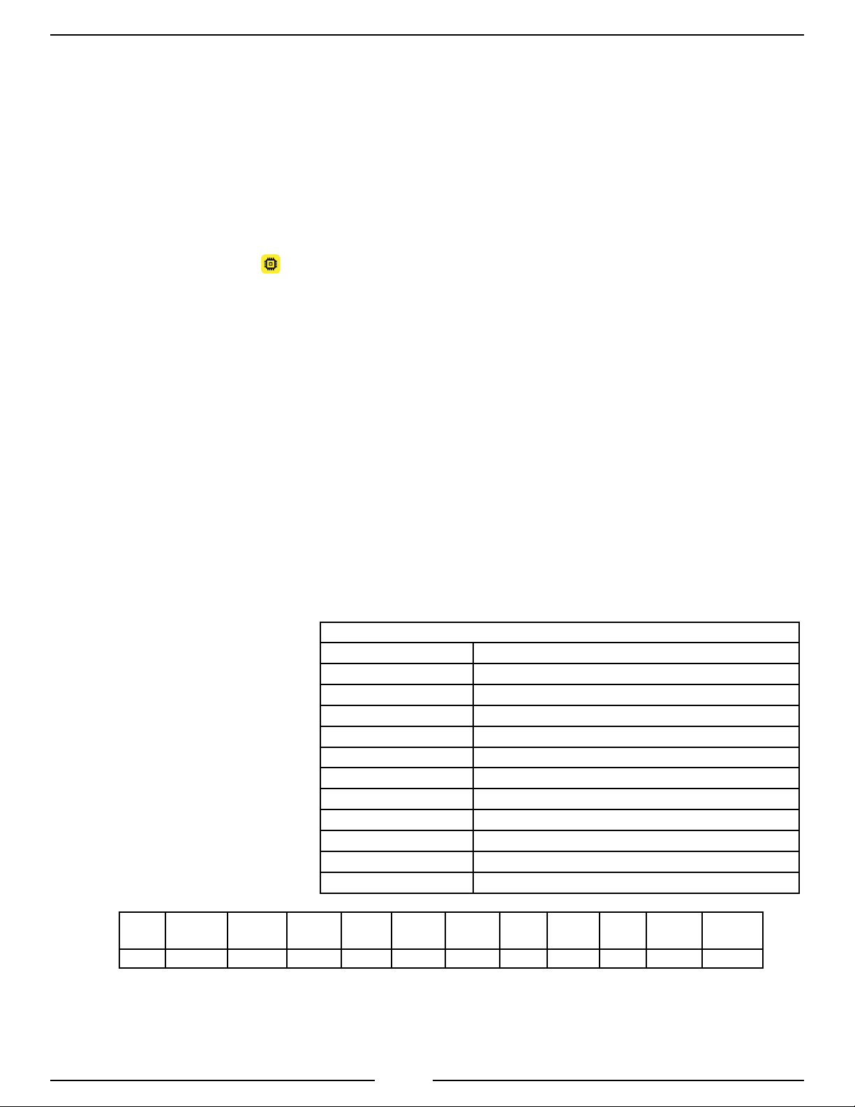
File Name Details:
A typical le name will appear as similar to the following:
FTC200_2014-11-26_10-54-01.csv
The above can be broken down as follows:
Model Number—FTC200
Year Recorded —2014
Month —11
Day —26
Hour —10
Minutes —54
Seconds —01
FTC-100 PORTABLE SAMPLING FLOW & PRESSURE METER REPORT
File Name FTC200_2014-11-26_10-54-01.csv
Software Version 0.31
Serial Number 1023
Test Date 2014/11/26
Test Time 10:54:02
No of Samples 1
Sample Rate (Minutes) 1
Unit of Measure KPA/LPM
Chan 1 Pipe Size 0.0 mm
Chan 2 Pipe Size 0.0 mm
Chan 3 Pipe Size 114.3mm
Chan 4 Pipe Size 0.0 mm
Sample
No.
1 11/26/2014 10:54:01 ---* ---* ---* ---* 1510 613 ---* ---* 1510
*Inactive Channel—when three dashes are shown, no data was recorded for that channel
Date Time Flow_1 Pres_1 Flow_2 Pres_2 Flow_3 Pres_3 Flow_4 Pres_4 Flow_Sum
Figure 2. Sample File Format
12
Page 13

FTC200 Rev151207
Computer Interface:
1. There is a computer connector port on the right side of the DataTron named "TO COMPUTER" .
This port allows for a direct data transfer to your computer (instead of with the USB ash drive). The
USB cable is provided as part no. XE-XXUSBEXT-C10A.
2. TO CONNECT: Connect the USB cable to the connector ports on the DataTron and to your computer.
Then press the button to the left of the computer port to connect the DataTron to your computer. The
DataTron will now appear as an external drive on your computer. The LED light will remain solidly on
once the connection is established.
3. TO DISCONNECT:
A) First close any open les.
B) Then safely remove the external drive through your computer software. (For example, Windows
users will see the safely remove hardware icon.)
C) Press the "TO COMPUTER" button and the LED light will shut off. The USB cable may
now be disconnected from both the DataTron and from your computer's USB port.
NOTE: The le format for use with a computer is the same as described with USB Data Retrieval on
the previous page.
NOTE: A rapidly ashing red LED light indicates that an action is being attempted by the user while
the DataTron is currently performing another action. The current action must either be completed
or disabled before a new action can be initiated. (For example, if the user is attempting to transfer
data via the USB cable while the unit is recording, both actions cannot be done simultaneously.)
13
Page 14

FTC200 Rev151207
PROGRAMMING
Programming functions are not allowed when the control module is in the recording mode.
All program functions are password protected.
The P-code program functions are available to view and change after the password code has been entered (see
below). Scroll through the P-codes. The value blinks and the UP and DOWN arrow buttons are used to
change that value or initiate an action. (If the value on the display does not blink, the value is read-only.) Use the
SELECT button to choose specic P-codes to change. The MENU button is used to save the changes; press and
hold this button to save (until 5 dashes appear – – – – – in the FLOW display).
Note: To exit programming modes, press the MENU button and return to normal operation.
Note: When entering codes in the program access mode there is a time out feature that requires an
operator input be made every three seconds. If an input is not detected at a button within three
seconds, the program will return to normal operation.
Note: A rapidly ashing red LED light indicates that an action is being attempted by the user while
the DataTron is currently performing another action. The current action must either be completed
or disabled before a new action can be initiated. (For example, if the user is attempting to transfer
data to a USB ash drive while the unit is recording, both actions cannot be done simultaneously.)
Enter Password for Program Access
1. Press and hold the MENU button for 3 seconds. The PRESSURE display shows four dashes – – – – .
Then release the MENU button.
2. Press the UP and DOWN arrow buttons to change the value. Each time a button is pressed the
rst digit changes by 1. Press the SELECT button to move to the next digit. Set the rst digit to the
desired number.
3. Repeat step 2 and enter the password code.
Result: When a correct password code is entered the PRESSURE display ashes the program (P) code
and the message display shows the name of the program or a description of the program code.
4. Press the UP and DOWN arrow buttons to scroll through the P-codes.
Operator Password 1221
Provides access to system programming P-codes.
1221 - Operator Programs
Refer to Operator P-100 Codes.
NOTE: Please see Program Code Descriptions for more detailed information on P-codes that refer to
specic user passwords according to the user level being accessed. This information is noted after
the P-codes table on pages 17-21.
14
Page 15

FTC200 Rev151207
OEM/Dealer Password Restricted (Contact FRC)
Provides access to system programming P200 and P300 codes.
Password Restricted - OEM/Dealer Programs
For more information, refer to the OEM/Dealer P200 and P300 Codes listed in the separate OEM
programming manual.
15
Page 16
FTC200 Rev151207
Operator P-100 Codes
• Refer to Program Code Descriptions for detailed information.
• When a valid code has been entered and a programed value or option is shown in the display, the timeout
feature is disabled.
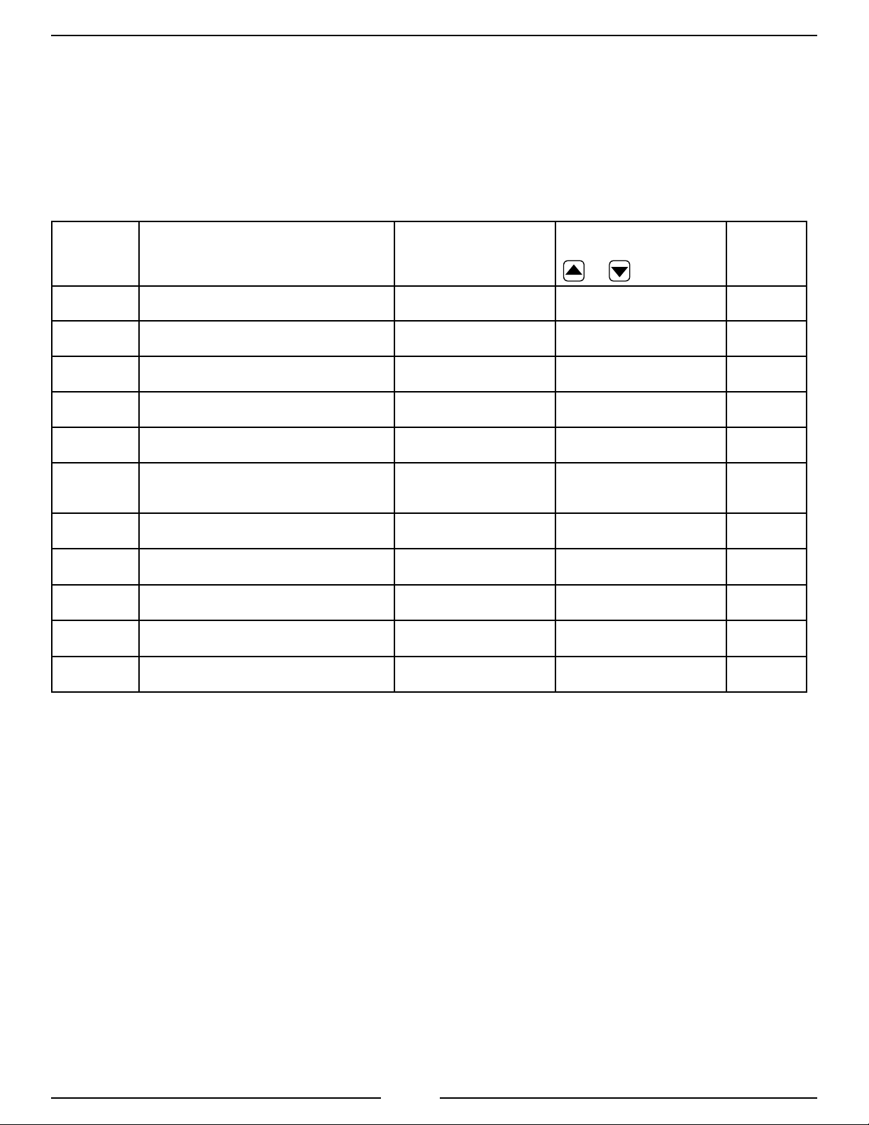
Table 1. Program Functions P-Codes Quick Reference
CODE DESCRIPTION
Password Code: 1221
Enables Access to P100
P101
P102
P103
P104
P105
P106
P107
P108
P109
P111
Displays System Model Number
Displays Software Revision
Displays Manufacturing Date
Displays Serial Number
Displays Hardware Revision
Displays Mac Address UID #
Displays/Edits Real-Time Date Value
Displays/Edits Real-Time Time Value
Firmware Update
Flow Calibration
MESSAGE DISPLAY
(See examples below.)
FTCXXX
r1.00
2014-12-08
985471
001
00-00-00-EF-10-23
2015-01-10
15:30
UPdAtE COdE
FLO CAL
Press SELECT button to
select; change value with
or buttons
(Read Only) n/a
(Read Only) n/a
(Read Only) n/a
(Read Only) n/a
(Read Only) n/a
(Read Only) n/a
(Read/Write) 18
(Read/Write) 18
(Procedure) 19
(Procedure) 20-21
Refer to
details on
pages
P112
Pressure Calibration
PRES CAL
(Procedure) 22
16
Page 17
FTC200 Rev151207
Set Date and Time (codes P107 and P108)
Set Date (Code P107*)
Enter password code 1221. (Refer to Enter Password for Program Access.)
1. Press the UP and DOWN arrow buttons and scroll to code P107 in the
PRESSURE display.
2. Press the SELECT button.
Result: The FLOW display shows the date with the year ashing.
3. Press the UP and DOWN arrow buttons to change the year.
4. Press the SELECT button.
Result: The month ashes.
5. Press the UP and DOWN arrow buttons to change the month.
6. Press the SELECT button.
Result: The day ashes.
7. Press the UP and DOWN arrow buttons to change the day.
8. Press and hold the MENU button for ve (5) seconds to save.
Result: The message display shows DONE.
*Note: When changing the date, please note that the year is represented with a "Y" on the left side of the FLOW display (e.g.,
Y-2014), month is symbolized with a lowercase "n", and "d" for the day. When adjusting the time, note the device runs on a
24 hour clock, and that minutes are represented by a lowercase "n". After the desired date, has been set, press MENU to hold
and save the entry.
Set Time (Code P108)
Enter password code 1221. (Refer to Enter Password for Program Access.)
1. Press the UP and DOWN arrow buttons and scroll to code P108.
2. Press the SELECT button.
Result: The FLOW display shows the time with the hours ashing.
3. Press the UP and DOWN arrow buttons to change hours.
4. Press the SELECT button.
Result: The message display shows time with the minutes ashing.
5. Press the UP and DOWN arrow buttons to change the minutes.
6. Press the SELECT button.
Result: The message display shows time with the AM/PM ashing.
7. Press the UP and DOWN arrow buttons to change the AM/PM.
8. Press and hold the MENU button for ve (5) seconds to save.
Result: The message display shows DONE.
17
Page 18

FTC200 Rev151207
Firmware Update (code P109)
Please read the following for instructions to conrm the software is updated to the current revision.
Firmware Update Steps
1. First make sure to have a USB ash drive compliant with USB 2.0 and formatted to the standard FAT32
le system available.
2. Copy the FTC200.hex le that you received from FRC onto your USB ash drive.
3. Enter the programming mode and scroll through the P-codes and select P109.
4. Insert your USB ash drive into the MEMORY port on the DataTron.
5. The COUNTS display will read as "no".
6. Use the UP and DOWN arrow buttons to change the setting to "y" (YES).
7. Press and hold the MENU button for approximately 3 seconds, and then let go. The LED light above
the MEMORY button will illuminate, and 5 dashes will appear on the FLOW display.
8. While the DataTron is updating, the dashes will scroll across the FLOW display.
9. The DataTron will power off and then restart automatically. Once the unit powers on again, the rmware
will be updated to the new revision. The current revision number will show on the PRESSURE display.
10. Power down and remove the USB ash drive.
18
Page 19

FTC200 Rev151207
Flow Calibration (code P111)
It is recommended that the owmeter/pressure indicator is checked after installation for accuracy and calibrated
when necessary
Review the Programming Section procedures for using the Program Access Mode.
NOTES:
1. Flow calibration must be done according to the designated preset. (Refer to P301 in the OEM Programming
Codes Manual.) For example, if P301 is set for PSI, the ow will be calibrated in GPM. Or, if P301 is
set for kilopascal (PCAL) or BAR, then ow will be calibrated in LPM instead.
2. It is recommended that the calibration of the meter be checked once annually or if the operator feels
that the reading might be erroneous.
3. To calibrate the owmeter, use a precalibrated water ow test kit (connected to the discharge
according to the instructions provided with the test kit) or a Pitot gauge as a reference.
4. If any error codes appear, refer to the error codes chart.
5. There must be at least a 5% difference between each calibration point. If a selected calibration point
is too close to the previous point, an E203 or E204 error code shows on the display.
6. The calibration data is stored inside of the paddlewheel sensor of the ow tube. This allows the ow
tube to be used in any ow/pressure channel of the currently used device or another DataTron.
Single Point Calibration
1. First be certain to connect the ow tube into the desired ow and pressure channel.
2. Flow water through the discharge at the ow rate selected for the calibration point. Ensure a constant
pressure is maintained to obtain a steady ow rate.
3. Enter the programming mode and scroll through the P-codes and select P111.
4. Press the SELECT button, and the display reads "SELECT CHAN"; the LEDs will start blinking the
displays for all four ow channels.
5. Press the button next to the desired ow channel to be calibrated. (Only one channel at a time can be
calibrated for ow. The LED next to the selected channel will illuminate, and the last known ow value
will appear on the FLOW display.
6. Using your calibration standard, enter the new or corrected ow value. (See note #1 above.)
7. Edit the value and once the calibration point has been entered in the FLOW display, press and hold the
MENU button until 5 dashes appear. Once the 5 dashes appear, the calibration point has been saved.
8. To exit, press the MENU button. The calibration point will be saved and appear in the FLOW display.
NOTE: See the beginning of the Programming section (on page 15) for detailed instructions to edit the
ow values on the DataTron with the UP and DOWN arrow buttons.
19
Page 20

FTC200 Rev151207
Multiple Point Calibration
1. First be certain to connect the ow tube into the desired ow and pressure channel.
2. Flow water through the discharge at the ow rate selected for the calibration point. Ensure a constant
pressure is maintained to obtain a steady ow rate.
3. Enter the programming mode and scroll through the P-codes and select P111.
4. Press the SELECT button, and the display reads "SELECt CHAn"; the LEDs will start blinking the
displays for all four ow channels.
5. Press the button next to the desired ow channel to be calibrated. (Only one channel at a time can be
calibrated for ow. The LED next to the selected channel will illuminate, and the last known ow value
will appear on the FLOW display.
6. Using your calibration standard, enter the new or corrected ow value. (See note #1 on page 19.)
7. Edit the value and once the calibration point has been entered in the ow display, press and immediately release
the MENU button. The COUNTS display will advance to the next point number (e.g. P2, P3 or P4).
8. To continue entering the next calibration point, adjust the ow rate to the desired number and then enter
into the FLOW display.
9. If you wish to enter another calibration point, adjust your ow rate, press the MENU button quickly and
release it to repeat the process described in number 7 (above).
10. Or to exit, then press and hold the MENU button to save the entered calibration points. (Five dashes will
appear, and the process is completed.) The calibration point will be saved and appear in the FLOW display.
NOTE: A maximum of four calibration points may be entered.
NOTE: See the beginning of the Programming section (on page 15) for detailed instructions to edit the
ow values on the DataTron with the UP and DOWN arrow buttons.
20
Page 21

Pressure Calibration (code P112)
NOTES:
1. Pressure calibration is done according to how the Unit of Measure was set in P301—either PSI,
BAR or kPa. (Refer to P301 in the OEM Programming Codes Manual.)
2. It is recommended that the calibration of the meter be checked once annually or if the operator feels
that the reading might be erroneous.
3. To calibrate the pressure indicator, use a precalibrated pressure indicator or gauge as a reference.
4. If any error codes appear, refer to the error codes chart.
5. There must be at least a 5% difference between each calibration point. If a selected calibration point
is too close to the previous point, an E203 or E204 error code shows on the display.
6. The calibration data is stored inside of the paddlewheel sensor of the ow tube. This allows the ow
tube to be used in any ow/pressure channel of the currently used device or another DataTron.
7. There are always two calibration points for Pressure Calibration (one lower and one upper value).
Pressure Calibration Steps
FTC200 Rev151207
1. First be certain to connect the ow tube into the desired ow and pressure channel.
2. Enter the programming mode and scroll through the P-codes and select P112.
3. Press the SELECT button, and the display reads "PrES CAL"; the LEDs will start blinking the displays
for all four ow channels.
4. Press the button next to the desired ow channel to be calibrated. (Only one channel at a time can be
calibrated for pressure.) The LED next to the selected channel will illuminate, and the last known pressure
value will appear on the PRESSURE display. The COUNTS display will read as P1.
5. Choose one lower point value (usually zero) and one higher point value. This rst value will show as 0
in the FLOW display.
6. Press and release the MENU button. The COUNTS display will read as P2.
7. Increase the pressure and enter the higher value into the FLOW display in kPa.
8. Press and hold the MENU button to save both calibration points. The process is complete.
21
Page 22
FTC200 Rev151207
Error Codes and Fault Warnings Troubleshooting Table
The table is provided to assist in tracking down system problems, it is not meant to take the
place of good troubleshooting practices.
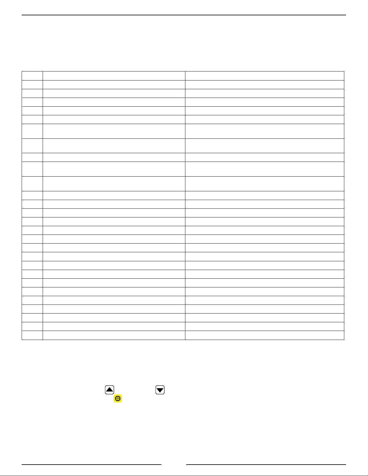
Table 2. Error Codes and Fault Warnings Troubleshooting
Code Description Probable Cause
E101
E102
E103
E104
Failed to read unique identier from calibrated pipe Check electrical connections between ow tube and channel input.
Failed to read data from calibrated pipe Check electrical connections between ow tube and channel input.
Failed to verify data written to a calibrated pipe Check electrical connections between ow tube and channel input.
Calibration data read from a pipe is not veriable Check electrical connections between ow tube and channel input.
E201
E202
E203
E204
E205
E301
E311
E312
E313
E314
E321
E322
E323
E324
E331
E332
E341
E342
E401
E402
E403
E404
User entered a (0) zero calibration value User entry error (conrm with detailed information for either codes
P111 or P112).
The paddlewheel or the pressure sensor data is reading a zero
value
The entered calibration point is to close to the previous point. See detailed information for multiple point ow calibration.
The paddlewheel or the pressure sensor data is reading a value
too close to another calibration point
The minimum number of calibration points has not been reached.
Power Supply Failure, Main 5 Volt Check connections between ow tube and channel input for a possible short.
Power Supply Failure, Pressure Channel 1 Check connections between ow tube and channel input for a possible short.
Power Supply Failure, Pressure Channel 2 Check connections between ow tube and channel input for a possible short.
Power Supply Failure, Pressure Channel 3 Check connections between ow tube and channel input for a possible short.
Power Supply Failure, Pressure Channel 4 Check connections between ow tube and channel input for a possible short.
Power Supply Failure, Flow Channel 1 Check connections between ow tube and channel input for a possible short.
Power Supply Failure, Flow Channel 2 Check connections between ow tube and channel input for a possible short.
Power Supply Failure, Flow Channel 3 Check connections between ow tube and channel input for a possible short.
Power Supply Failure, Flow Channel 4 Check connections between ow tube and channel input for a possible short.
Power Supply Failure, User USB Memory Check connections between ow tube and channel input for a possible short.
Power Supply Failure, Internal USB Memory Check connections between ow tube and channel input for a possible short.
Power Supply Failure, J1939 Check connections between ow tube and channel input for a possible short.
Power Supply Failure, FRC CAN Check connections between ow tube and channel input for a possible short.
Internal Error Contact FRC and advise the code number.
Internal Error Contact FRC and advise the code number.
Internal Error Contact FRC and advise the code number.
Internal Error Contact FRC and advise the code number.
No water ow or pressure detected - check the electrical connections
between the Flow Sensor and the Flow Tester Cable.
See detailed information for multiple point ow calibration.
Pressure requires a least 2 points. The user pressed and held MENU
before the second point was entered.
Steps to Obtain an Error Log:
1. Insert a USB ash drive (compliant with USB 2.0 and formatted to the standard FAT32 le system) into
the data port on the right side of the DataTron labeled MEMORY.
2. Press both the UP and DOWN arrow buttons at the same time until the LED light comes on
above the MEMORY button.
3. When the LED light goes out, remove the USB ash drive.
4. Insert the USB ash drive into the your computer's USB port. The Error Log will appear with the le
name "error.txt". This le can be read with any standard text editor such as Windows® Note Pad.
22
Page 23

PART NO. DESCRIPTION
XE-FTC200-D0A DM Flow & Pressure 4-Channel Recorder
XE-FTIPFPM-C20A Cable, Flow Tester IPF-PM 20-ft
XE-XXPSAA30R-150 Battery Charger/Power Supply
XE-FTC12V-A1A Charger Cable, DC, Alligator Clips
XE-PRO31PT3-S0B Pressure Sensor
XE-MF40P-S0A Flow Sensor (Paddlewheel)
XE-XXUSBEXT-C10A Cable, Ext. USB Mini-B 10-ft (laptop to FTC200)
XE-XXBC-ZA5074-B Charger Cable, DC, Accessory Plug 12V BA
XE-XX552-RPA-R Adapter, AC 12V 2.5A 30W Wall Adapter
XE-XXPLUGDEU2P-A0A
XE-XX6PDP-A0A Seal Plug, 6-Pin (for Flow Tube channels)
Seal Plug, 2-Pin (for POWER port)
NOTE: Per your testing requirements, 1-4 ow tubes can be ordered with the
corresponding number of ow/pressure sensors and harnesses. The size of
each ow tube can be specic to your requirements.
FTC200 Rev151207
PARTS LIST
Flow Sensor (Paddlewheel)
Part No. XE-MF40P-S0A
Cable, Ext. USB Mini-B 10-ft
Part No. XE-XXUSBEXT-C10A
Cable, Flow Tester IPF-PM 20-ft
Part No. XE-FTIPFPM-C20A
Accessory Plug
Part No. XE-XXBC-ZA5074-B
Pressure Sensor
Part No. XE-PRO31PT3-S0B
Charger Cable, DC, Alligator Clips
Part No. XE-FTC12V-A1A
Table 3. Parts List
23
Page 24

FTC200 Rev151207
Specications
Display Module (mounted inside Pelican Case 1400)
Supply Voltage: 10 - 30 VDC
Supply Power: 15 Watts
Case Exterior Dimensions: 13.37 x 11.62 x 6 inches (L x W x D)
34 x 29.5 x 15.24 cm (L x W x D)
Operating Temperature (non-condensing): -30°C to 55°C (-22°F to 131°F)
Storage Temperature (non-condensing): -40°C to 60°C (-40°F to 140°F)
NOTE: Do not store the DataTron in either extreme hot or cold temperature environments.
IP Rating: 67—with seal plugs in place and case closed
Typical Battery Run Time: 8 hours (from full charge)
Typical Battery Charge Time: 4-5 hours
Flow Tubes
Material: Aluminum
Sizes Available: 1.5" Tube w/2.5" Couplings (13 - 320 GPM)
2.0" Tube w/2.5" Couplings (21 - 520 GPM)
2.5" Tube w/2.5" Couplings (30 - 850 GPM)
3.0" Tube w/NPT Threads (40- 1380 GPM)
4.0" Tube w/NPT Threads (80 - 2300 GPM)
Note: GPM rating is at 0 PSI back pressure (no obstruction at end of tube).
Flow Sensor
Model Number: XE-MF40P-S0A
Type: Paddlewheel
Sensor Material: Acetal (Delrin) with Stainless Steel (316) Shaft
Excitation Voltage: 5 VDC
Calibration: 4 kb Internal Memory Storage
Pressure Sensor
Model Number: XE-PRO31PT3-S0B
Pressure Range: 0 - 300 PSI
Proof Pressure: 800 PSI
Type: Stainless Steel
Excitation Voltage: 5 VDC
Output Voltage: 0-5 VDC- 4.75 VDC (See Table 4.)
24
Page 25
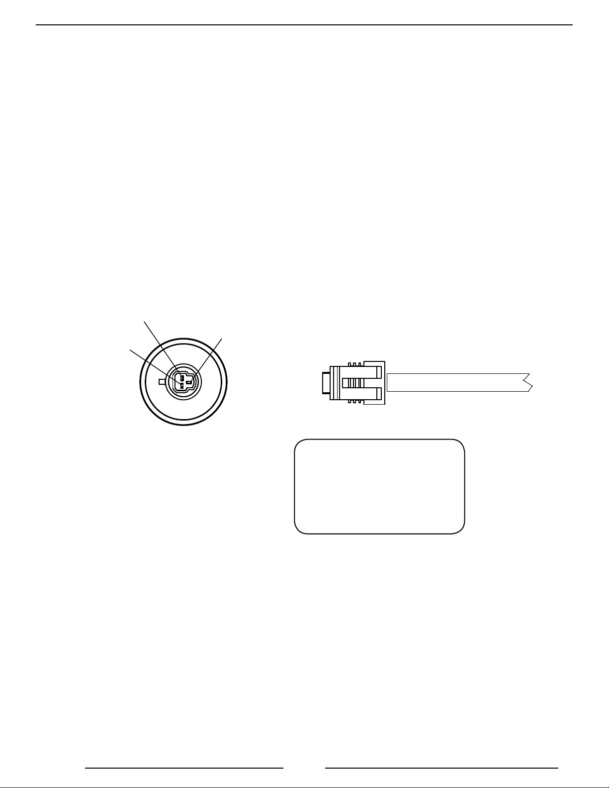
Flow Sensor
Flow Sensor
(Top View)
Supply
Voltage
Ground
Signal
Output
FTC200 Rev151207
Sensor Cable from
8-Pin Connector
Sensor Cable
3-Pin Connector
Pin/Wire Description
A/Black Ground
B/Red Supply Voltage
C/White Signal
Figure 3. Flow Sensor Wiring
25
Page 26

FTC200 Rev151207
Pressure Sensor
Model Number: XE-FTC200-D0A
Pressure Range: 0 - 300 PSI
Proof Pressure: 800 PSI
Type: Stainless Steel
Excitation Voltage: 5 VDC
Output Voltage: 0-5 VDC- 4.75 VDC (See Table 1)
Table 4. Pressure Sensor Output Voltage
0 psi 100 psi 150 psi 200 psi 250 psi 300 psi 600 psi
FTC200
XE-FTC200-D0A 0.5 vdc 1.917 vdc 2.625 vdc 3.33 vdc 4.04 vdc 4.75 vdc N/A
26
Page 27
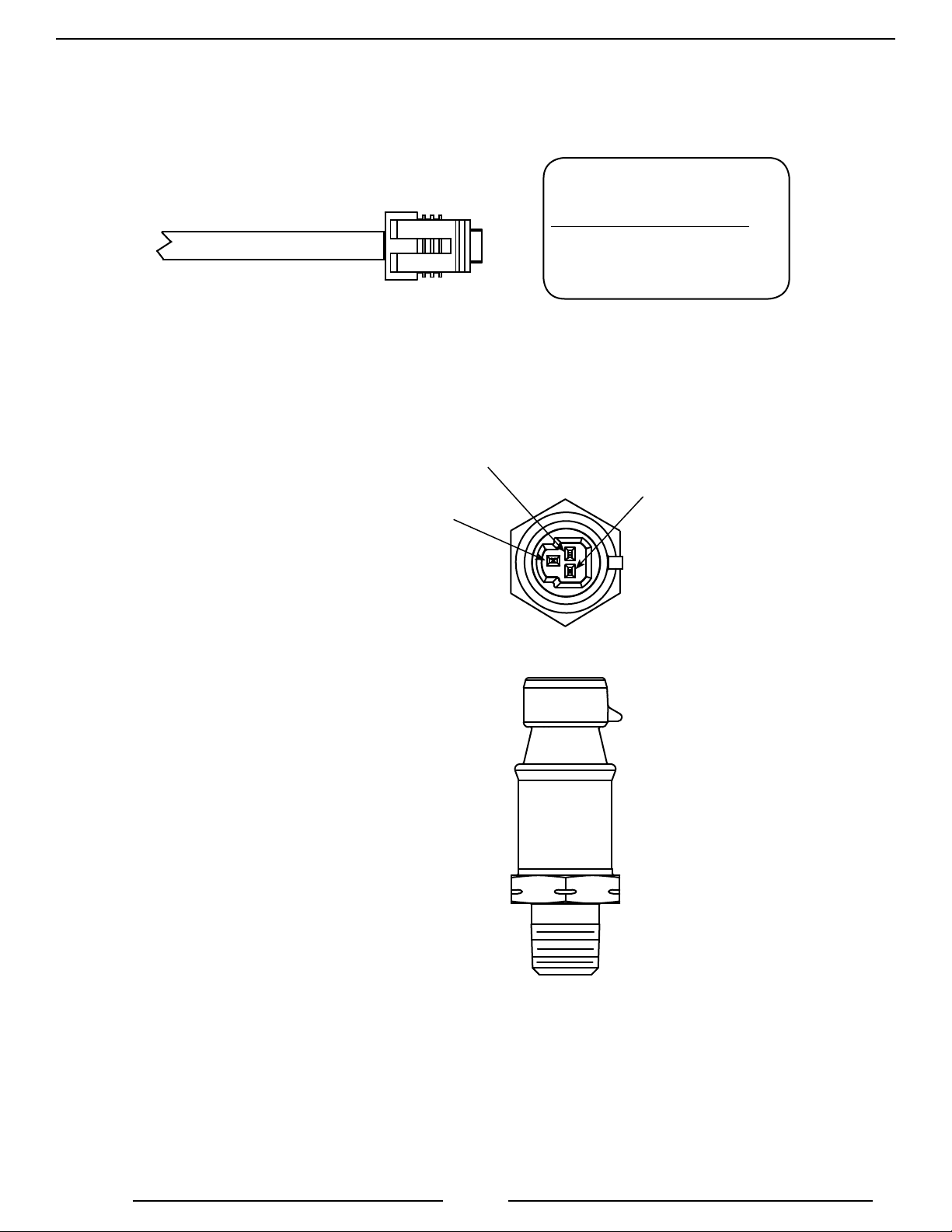
Pressure Sensor
FTC200 Rev151207
Pressure Sensor
Cable
Pressure Sensor
Top View
Signal
Output
Ground
Pressure Sensor Cable
3-Pin Connector
Pin/Wire Description
A/Black Ground
B/Red Supply Voltage
C/White Signal
Supply
Voltage
Pressure Sensor
Side View
Figure 4. Pressure Sensor Wiring
27
Page 28
FTC200 Rev151207
FLOW SENSOR MAINTENANCE
It is recommended that the ow sensor be cleaned during the yearly calibration check.
Depending on the environment that the ow tube is used in, it is possible that mud, grass, algae, or other
materials may collect on the paddlewheel of the ow sensor and require it to be cleaned from time to time.
Remove the ow sensor and clean the it with a mild soap and clean water. Make sure the paddlewheel spins
freely.
Remove Flow Sensor
1. Remove retaining nut.
2. Slide ow sensor out of sensor housing.
Install Flow Sensor
1. Insert ow sensor into sensor housing. Align at spot on sensor rim with alignment tab and make sure
O-ring is in groove.
Note: The retainer cap only needs to be hand tightened. There is an inside lip that will stop the cap from
turning when it makes contact with the alignment tab. This provides the correct pressure to make the
seal at the O-ring. Make sure the ow sensor does not disengage from the alignment tab and rotate.
2. Install retainer cap and hand tighten.
Alignment Tab
Retainer
Cap
Paddle Wheel
Flow Sensor
O-Ring
Sensor
Housing
Typical
Flow Tube
Figure 5. Flow Sensor Maintenance
28
Page 29

NOTES
FTC200 Rev151207
29
Page 30

FTC200 Rev151207
NOTES
30
Page 31

NOTES
FTC200 Rev151207
31
Page 32

FTC200 Rev151207
32
 Loading...