


4” and 6” SUBMERSIBLE PUMPS
OWNER'S MANUAL
BEFORE INSTALLING PUMP, BE SURE TO READ THIS OWNER’S MANUAL CAREFULLY.
 CAUTION Fill pump with water before starting or pump will be damaged. The motor on this pump is guaranteed by the manufacturer. In event of failure it must be returned to an authorized service station for repairs. Motor warranty is void if repairs are not made by an authorized repair station.
READ AND FOLLOW SAFETY INSTRUCTIONS
This is the safety alert symbol. When you see this symbol on your pump or in this manual, look
for one of the following signal words and be alert to the potential for personal injury:
 D A N G E R warns about hazards that will cause serious personal injury, death or major property damage if ignored.
 WARNING warns about hazards that can cause serious personal injury, death or major property damage if ignored.
 CAUTION warns about hazards that will or can cause minor personal injury or major property damage if ignored.
The label NOTICE indicates special instructions, which are important but not related to hazards.
Carefully read and follow all safety instructions in this manual and on pump.
Keep safety labels in good condition.
Replace missing or damaged safety labels.
 WA R N I N G
Hazardous voltage. Can shock, burn, or cause death.
Ground pump before connecting to power supply. Disconnect power before working on pump, motor
or tank.
 WARNING Wire motor for correct voltage. See “Electrical” section of this manual and motor nameplate.
 WARNING Ground motor before connecting to power supply.
 WARNING Meet National Electrical Code, Canadian Electrical Code, and local codes for all wiring.
INSPECT THE SHIPMENT
Examine the pump when it is received to be sure there has been no damage in shipping. Should any be evident, report it immediately to the dealer from whom the pump was purchased. Please check the pump package to see that it includes pump, motor, and motor leads (if your pump purchase includes a motor).
Follow wiring instructions in this manual when connecting motor to power lines.
106467101 Rev. 12 11.14

 WARNING
IMPORTANT INFORMATION FOR INSTALLERS OF THIS EQUIPMENT!
THIS EQUIPMENT IS INTENDED FOR INSTALLATION BY TECHNICALLY QUALIFIED PERSONNEL. FAILURE TO INSTALL IT IN COMPLIANCE WITH NATIONAL AND LOCAL ELECTRICAL CODES, AND WITH FRANKLIN ELECTRIC RECOMMENDATIONS, MAY RESULT IN ELECTRICAL SHOCK OR FIRE HAZARD, UNSATISFACTORY PERFORMANCE, AND EQUIPMENT FAILURE. FRANKLIN INSTALLATION INFORMATION IS AVAILABLE FROM PUMP MANUFACTURERS AND DISTRIBUTORS, AND DIRECTLY FROM FRANKLIN ELECTRIC. CALL FRANKLIN TOLL FREE 800-348-2420 FOR INFORMATION. RETAIN THIS INFORMATION SHEET WITH THE EQUIPMENT FOR FUTURE REFERENCE.
 WARNING
SERIOUS OR FATAL ELECTRICAL SHOCK MAY RESULT FROM FAILURE TO CONNECT THE MOTOR, CONTROL ENCLOSURES, METAL PLUMBING, AND ALL OTHER METAL NEAR THE MOTOR OR CABLE, TO THE POWER SUPPLY GROUND TERMINAL USING WIRE NO SMALLER THAN MOTOR CABLE WIRES. TO REDUCE RISK OF ELECTRICAL SHOCK, DISCONNECT POWER BEFORE WORKING ON
OR AROUND THE WATER SYSTEM. DO NOT USE MOTOR IN SWIMMING AREAS.
INSTALLATION RECORDS
It is good idea to keep an accurate record of your installation. Be sure to record the data below:
Purchased From:
Date of Installation:
Pump Model No.*
Pump Date Code*
Well Inside Dia.(in/mm):
Depth of Well(ft/m):
Depth of Water(ft/m):
Pump Setting(ft/m):
Drop Pipe Size:
Wire Size(pump to control box):
Wire Size(control box to power source):
Horizontal Offset(between well & house):
Make of Motor*
Amps |
|
HP |
Volts |
|
Ph |
|
|
|
|
|
|
|
|
|
|
|
|
|
Make of Control Box |
|
|||
|
|
|
|
||
HP |
|
Volts |
|
||
|
|
|
|
|
|
|
|
|
|
|
|
|
|
Power Supply |
|
||
|
|
|
|
||
Volts |
|
HZ |
|
||
|
|
|
|
||
|
|
|
|
|
|
|
Pressure Switch (PSI) |
|
|||
|
|
|
|
||
Cut-in |
|
Cut-out |
|
||
|
|
|
|
|
|
|
|
|
|
|
|
* This Information is on your pump or motor tag. It will help us identify your pump in case of later inquiries.
TEST RUNNING
If test running pump before installation:
1.Insure that the power supply corresponds with that shown on the nameplate of the motor and control box. (if required).
2.Install pump and components appropriate for the test as shown in Fig. 1.
3.Make sure power supply is turned off and circuit breaker or disconnect switch is open. Make electrical connections appropriate to your motor as shown in Fig. 2, 3 or 4.
4.THREE-PHASE UNIT - A three-phase motor requires a magnetic starter equipped with quick-trip, ambient compensated heaters of correct size for the horsepower of the motor. To insure correct rotation of three-phase units, brace pump shell securely and apply power momentarily by snapping line switch quickly on and off.
2
If rotation is correct, reaction of the shell will be clockwise when viewed from pump discharge (that is, pump shaft will rotate counter clockwise). Interchange any two leads at magnetic starter to reverse rotation.
5. Run pump and motor unit for a few seconds to ensure that it is in working order.
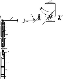
FIGURE 1 - Installation Diagram
|
|
|
Pressure Tank |
|
|
See Wiring Diagrams |
|
|
|
|
Pressure Switch |
Sanitary Well Seal |
|
Spring-Loaded |
Gate Valve |
|
Check Valve |
||
or Pitless Adapter |
|
||
Discharge Pipe |
|
|
|
|
|
|
|
|
Submersible Cable |
Pressure Relief Valve |
Service Pipe |
|
|
Pressure Gauge |
|
|
Spring-Loaded |
|
|
|
Check Valve |
|
|
|
(Recommended every 100’/30m) |
|
|
|
Safety Cable |
|
|
Drop Pipe |
Submersible Cable |
|
|
|
(secured to drop |
|
|
|
pipe with tape or |
|
|
|
clamps every 10’/3m) |
|
|
|
Torque Arrestor |
|
|
|
Well Casing |
|
|
|
Spring-Loaded |
|
|
|
Check Valve |
|
|
|
at Pump Discharge |
|
|
|
Submersible |
Note: Keep pump at least 5’ from |
|
|
Pump Unit |
bottom of well and above well screen |
|
|
Suction Screen |
or casing perforations. |
|
|
|
|
|
|
Motor |
|
|
Well Screen or
Casing Perforations
SUITABILITY OF WELL
Install the pump only in a well that has been properly developed.Water from an undeveloped well often contains an excessive amount of sand, dirt, and abrasives which can damage the pump. Check that the well is large enough to allow the pump to be set at the required depth. Do not set the pump below the casing perforations or well screen unless you make arrangements to ensure an adequate flow of water over the motor for cooling purposes. Determine the correct pump setting from the driller’s record by taking into account the static water level and the drawdown at the proposed pumping rate. Keep the pump at least five feet from the bottom of a drilled well.
SPLICING THE POWER CABLE
Follow the instructions enclosed in the cable splicing kit you purchase.
DROP PIPE
Drop pipe is recommended for suspending submersible pumps into the well. Please refer to pipe manufacturer for recommendations on depth and pressure. Give special consideration to:
1.A safety cable to prevent loss of pump if pipe should break.
NOTICE: IT IS RECOMMENDED THAT STEEL CABLE BE USED FOR THE PURPOSES OF SECURING THE PUMP. 3/16" DIAMETER TO 1/4" DIAMETER BRAIDED STEEL CABLE IS SUFFICIENT TO SUPPORT MOST PUMP/MOTOR ASSEMBLIES. IT IS ALWAYS BEST TO CONFIRM THAT THE PUMP/MOTOR ASSEMBLY DOES NOT EXCEED THE MAXIMUM WEIGHT LIMIT OF THE CABLE SELECTED.
2.Torque arrestor just above pump to prevent chafing the cable when pump and pipe twist during the starting and stopping cycle. (See Figure 1)
Take great care to keep pipes clean and free from pebbles, scale and thread chips. Make sound, air-tight connections at all fittings. Pipe sealant is recommended.
CHECK VALVES
It is recommended that one or more check valves always be used in submersible pump installations. If the pump does not have a built-in check valve, an inline check valve should be installed in the discharge line within 25 feet of the pump and below the draw down level of the water supply. For deeper settings, check valves should be installed per the manufacturer's recommendations. More than one check valve is often needed, but more than the recommended number of check valves should not be used.
Swing type check valves are not acceptable and should never be used with submersible motors/pumps. Swing type check valves have a slower reaction time which can cause water hammer (see next page). Internal pump check valves or spring loaded check valves close quickly and help eliminate water hammer.
NOTE: Only positive sealing check valves should be used in submersible installations. Although drilling the check valve or using drain-back check valves may prevent back spinning, they create upthrust and water hammer problems.
Check valves are used to hold pressure in the system when the pump stops. They also prevent backspin, water hammer and upthrust. Any of these can lead to early pump or motor failure.
A. Backspin - With no check valve or a failed check valve, the water in the drop pipe and the water in the system can flow down the discharge pipe when the motor stops. This can cause the pump to rotate in a reverse direction. If the motor is started while it is backspinning,
3

an excessive force is placed across the pump-motor assembly that can cause impeller damage, motor or pump shaft breakage, excessive bearing wear, etc.
B.Upthrust - With no check valve, a leaking check valve, or drilled check valve, the unit starts under a zero head condition. This causes an uplifting or upthrust on the impeller-shaft assembly in the pump. This upward movement carries across the pump-motor coupling and creates an upthrust condition in the motor. Repeated upthrust can cause premature failure of both the pump and the motor.
C.Water Hammer - If the lowest check valve is more than 30 feet above the standing (lowest static) water level, or a lower check valve leaks and the check valve above holds, a vacuum is created in the discharge piping. On the next pump start, water moving at very high velocity fills the void and strikes the closed check valve and the stationary water in the pipe above it, causing a hydraulic shock.This shock can split pipes, break joints and damage the pump and/ or motor.Water hammer can often be heard or felt.When
discovered, the system should be shut down and the pump installer contacted to correct the problem.
REMOVABLE POPPET CHECK VALVE
Some submersible pumps are supplied with a REMOVABLE check valve assembly for applications where the pump can become air locked. If the pump is supplied without a check valve, or if the check valve is removed, a spring-loaded inline check valve should be installed roughly 10 to 20 feet (3 to 6.09 meters) above the pump. This allows for the repriming of the pump after the pump has run out of water.
 WARNING Fluid draining back through the pump can cause the pump to rotate backwards. If pump/ motor starts during this time; damage to the pump can occur.
The check valve can be removed with the use of the T-Handle Poppet Wrench (part no. 23498207), ordered separately, or, with standard needle nose pliers. The poppet assembly is left hand threaded and is removed by turning CLOCKWISE.
If reinstalling a Popppet Check Valve assembly, the assembly should be tightened to 15 inch-pounds.
Poppet Assembly |
T-Handle Poppet Wrench |
INSTALLATION OF PUMP, DROP PIPE, AND ASSOCIATED EQUIPMENT
Fig. 1 illustrates a typical well installation showing inground components. Franklin recommends the following procedure when installing the pump and drop pipe:
1.Prior to fastening the pump/motor assembly to the drop pipe, confirm that the motor’s lead wires are securely housed under lead guard which was
supplied with the pump. Fastening screws have been provided for use during the lead guard’s installation.
2.Fasten the submersible cable to the drop pipe with clamps or appropriate tape every 10 ft. (3m) to prevent tangling and damage to the cable. The cable must remain slack when using plastic drop pipe to allow for stretching of pipe when installed in the well.
3.Take care not to scrape or pinch the submersible cable against the well casing.
4.Use an ohmmeter or megger to make insulation and continuity checks on the cable once the pump is installed. This locates any fault in the cable.
5.Make sure system check valves are installed properly. See previous sections of this manual for further information on check valve placement, type, and troubleshooting.
6.Install a torque arrestor just above the pump to prevent chafing the cable when pump and pipe twist during starting and stopping.
7.Attach a safety cable to pump to prevent loss of pump if pipe should break.
NOTICE: IT IS RECOMMENDED THAT STEEL CABLE BE USED FOR THE PURPOSES OF SECURING THE PUMP. 3/16" DIAMETER TO 1/4" DIAMETER BRAIDED STEEL CABLE IS SUFFICIENT TO SUPPORT MOST PUMP/MOTOR SYSTEMS. IT IS ALWAYS BEST TO CONFIRM THAT THE PUMP/MOTOR SYSTEM DOES NOT EXCEED THE MAXIMUM WEIGHT LIMIT OF THE CABLE
SELECTED.
8.Place a sanitary well seal or pitless adapter with an approved cover plate over top of well per manufacturers recommendations.
9.Keep pump at least 5’ (1.5m) from bottom of well and above well screen or casing perforations.
4

ELECTRICAL INFORMATION
1.Employ a licensed electrician to perform the wiring. All wiring must be done in accordance with applicable national and local electrical codes.
2.Check that the power supply corresponds with the electrical rating of the submersible motor and the control box(if required). Make sure that the control box electrical rating matches the motor electrical rating.
3.Every installation requires a fused disconnect switch or circuit breaker.
4.Every installation must be grounded. There must be a reliable ground connection between the pump and the distribution panel. The motor lead incorporates a green grounding conductor.
5.Lightning arrestors are recommended for every installation. All stainless steel, single phase motors thru 5HP have built-in lightning arrestors. Any 6” motor or 4”, 3-phase motor requires a separate lightning arrestor installed as close to the wellhead as possible. Install the arrestor in accordance with manufacturers recommendations. A lightning arrestor provides protection against induced voltage surges on
6.Mount the control box in an area protected from rain, snow, direct sunlight or other high temperatures as this may cause tripping of the overload protector.
Also protect the control box from extreme cold (below 25oF/-32oC) as this may have adverse effects on starting capacitor.
7.A two-wire pump does not require a motor control box, since all electrical components are built inside the motor. Fig. 2 shows a typical wiring diagram for a two-wire installation.
FIGURE 2 - 2 WIRE, 1-Phase, 1/2 thru 1-1/2 HP Pump Wiring Diagram


 Circuit Breaker or
Fuse Disconnect Switch
Switch or Timer
 Submersible Cable
Incoming 1-Phase Power
1-Phase Submersible Motor
8.A three-wire, single-phase pump requires a motor control box incorporating overload relays. Fig. 3 shows a typical wiring diagram for a three-wire, single-phase installation. Note that a magnetic contactor must be used if the pressure switch electrical rating is not sufficient to handle the submersible motor electrical rating. The pressure switch would then be incorporated into a pilot circuit to control the magnetic contactor. Make the connections at the control box in accordance with the wiring diagram in the control box to avoid damage to the motor.
FIGURE 3 - 3-WIRE, 1-Phase, 1/2 thru 3 HP Pump Wiring Diagram
|
Note: Order of red, yellow and black may |
|
Pressure Switch (for pilot circuit) |
vary from control box to control box. |
|
Always connect like colors. |
||
If Magnetic Contactor is used |
Single-Phase |
|
for starting. |
||
Control Box |
||
|
||
Circuit Breaker |
|
|
or Fused Disconnect Switch |
L1 L2 R Y B |
|
|
||
Incoming 1 Phase Power |
Red |
|
|
||
|
Yellow |
|
|
Black |
|
Switch or Timer (for direct switching) OR |
||
Magnetic Contactor (w/ pilot circuit) |
|
|
1-Phase Sumbersible Motor |
||
5
9.A three-phase pump does not require a motor control box . Fig. 4 shows a typical wiring diagram for a 3-wire, three-phase installation. A magnetic contractor with 3-leg protection having quick-trip ambient compensated overload relays must be used.
FIGURE 4 - 3-Wire, 3-Phase, 1-1/2 thru 50 HP Pump Wiring Diagram
Circuit Breaker OR |
Pressure Switch |
|
|
Fused Disconnect Switch |
|
|
Magnetic Contactor w/ |
|
3-leg protection having |
|
quick-trip ambient |
|
conpensated overload relays |
Incoming 3-Phase Power |
|
3-Phase Submersible Motor
10.Use an ohmeter to make continuity and insulation checks after the installation is completed.
11.Place the additional motor label with the pump label and place both in the disconnect switch or circuit breaker box for future reference.
WELL TEST
Check the pump and well performance before making the final connection to the discharge system.
1.Install a gate valve on the end of the pipe. Partially open the valve.
2.Start the pump.
3.Open valve gradually to give full flow.
4.If the discharge is not clear, let the pump run until water clears. If water does not clear in 30 minutes, stop the pump and take the necessary steps to correct the condition. After the water has appeared clear, check for sand by discharging into a clean bucket or suitable container.
5.Close valve until maximum required system flow rate is obtained (this should correspond to the cut-in pressure of the pressure switch). Ensure that the output of the pump at this setting is not greater than the yield of the well. This can be checked by monitoring the well drawdown level and ensuring that the level is stable at the maximum required system flow rate.
 CAUTION Never run pump unless it is completely submerged in water. If run without water, the pump and motor could be damaged. Note also that air drawn into the pump can cause an airlock under certain conditions.
LOW-YIELDING WELL
A low-yielding well exists when the output from the pump is greater than the yield of the well. It can reduce the water level to the suction screen so that a mixture of air and water enters the pump. Pumping may stop since the pump cannot generate pressure
with insufficient water. In this case, the column of water already in the drop pipe holds the check valve closed and an airlock may develop inside the pump. Because the conditions ensure neither adequate lubrication of the pump nor proper cooling for the motor, damage can result if power is not cut off quickly. Use one or more of the following methods to correct and/or protect this installation.
1.Install additional length of drop pipe to place pump lower in well if possible.
2.Install a Franklin Pumptec or similar electronic drawdown sensor.
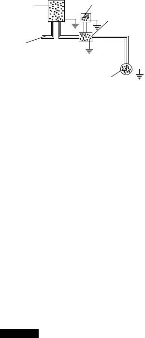
3.Install a floatless liquid level control. This device consists of an electrical relay activated by currents flowing through the ground-return circuits of electrodes hung in the well. The lower (STOP) electrode, just above the pump, ensures that the water level can never be pumped down to the suction screen. The upper (START) electrode, just below the lowest static water level, ensures that the pump can start again as soon as the well has recovered. A floatless liquid level control works
in series with the pressure switch. Refer to the manufacturers instructions provided with control.
4.Install a flow control valve in the discharge line upstream from the pressure switch. This restricts the output from the pump without affecting the rate that water can be drawn from the pressure tank. Nevertheless, a heavy demand for water could empty the pressure tank, so a tank with a bonded diaphragm, air cell, or water bag is recommended.
5.Install a smaller pump to avoid over pumping the well. Have dealer size pump to the well yield.
6.Install a low-pressure cut-off switch. A low pressure cut off switch, or a pressure switch with such an arrangement built in, protects a shallow-well pump from losing its prime, but it does not always provide satisfactory protection to a submersible pump from the effects of over pumping the well. This is because it responds to a loss of pressure at the surface, which may occur after an air lock has formed inside the pump. We recommend either a floatless liquid level control or a flow control valve, in that order,
in preference to a low-pressure cutoff switch as protection against over pumping.
6
DISCHARGE PLUMBING
Fig. 1 illustrates a typical well installation showing above ground components. Adhere to the following items when installing the discharge plumbing.
1.Install an above ground check valve upstream from the pressure switch.
2.Always install a pressure relief valve in the system. The relief valve should be capable of discharging the flow rate of the pump at the rated working pressure of the pressure tank. Locate the relief valve close to the pressure tank.
3.Install a pressure switch between the check valve and the pressure tank. Refer to Fig. 2, 3, or 4 for proper wiring connections of pressure switch.
4.Install a pressure tank as close as possible to the pressure switch. Refer to manufacturer’s recommendations for installation.
TROUBLESHOOTING
1.PUMP FAILS TO START
a)Electrical trouble - call dealer or electrician.
b)Drawdown protection device has pump turned off.
c)Overload tripped.
d)Reset low pressure cutoff switch (if installed).
2.PUMP FAILS TO DELIVER WATER
a)Air lock in pump.
b)Clogged intake screen.
c)Insufficient well yield.
3.PUMP GIVES REDUCED OUTPUT
a)Insufficient well yield.
b)Worn pump.
c)Clogged intake screen.
d)Low voltage.
e)Incorrect rotation (3-phase only).
4.PUMP CYCLES TOO FREQUENTLY
a)Excessive pressure drop between pressure switch and pressure tank.
b)“Cut-in” pressure at pressure tank too high.
c)“Cut-out” pressure at pressure tank too low.
d)Waterlogged pressure tank.
e)Start and stop electrodes of floatless liquid level control set too close together.
f)Tank sized too small to meet system requirements.
5.OVERLOADS TRIP
a)Electrical trouble - call dealer or electrician.
6.PRESSURE SWITCH CYCLES RAPIDLY WHEN PUMP STARTS
a)Pressure switch too far from pressure tank.
b)Adjust air charge of tank to manufacturer’s recommendations.
7
LIMITED WARRANTY*
THIS WARRANTY SETS FORTH THE COMPANY’S SOLE OBLIGATION AND PURCHASER’S EXCLUSIVE REMEDY FOR DEFECTIVE PRODUCT.
Franklin Electric Company, Inc. and its subsidiaries (hereafter “the Company”) warrants that the products accompanied by this warranty are free from defects in material or workmanship of the Company.
The Company has the right to inspect any product returned under warranty to confirm that the product contains a defect in material or workmanship. The Company shall have the sole right to choose whether to repair or replace defective equipment, parts, or components.
The buyer must return the product to an authorized Franklin Electric Distribution outlet for warranty consideration. Returns to the place of purchase will only be considered for warranty coverage if the place of purchase is an authorized Franklin Electric Distributor at the time the claim is made. Subject to the terms and conditions listed below, the Company will repair or replace to the buyer any portion of this product which proves defective due to materials or workmanship of the Company.
The Company will consider products for warranty for 12 months from the date of installation or for 24 months from the date of manufacture, whichever occurs first.
The Company shall IN NO EVENT be responsible or liable for the cost of field labor or other charges incurred by any customer in removing and/or affixing any product, part or component thereof.
The Company reserves the right to change or improve its products or any portions thereof without being obligated to provide such change or improvement to previously sold products.
THIS WARRANTY DOES NOT APPLY TO products damaged by acts of God, including lightning, normal wear and tear, normal maintenance services and the parts used in connection with such service, or any other conditions beyond the control of the Company.
THIS WARRANTY WILL IMMEDIATELY VOID if any of the following conditions are found:
1.Product is used for purposes other than those for which it was designed and manufactured;
2.Product was not installed in accordance with applicable codes, ordinances and good trade practices;
3.Product was not installed by a Franklin Certified Contractor; or
4.Product was damaged as a result of negligence, abuse, accident, misapplication, tampering, alteration, improper installation, operation, maintenance or storage, nor to an excess of recommended maximums as set forth in the product instructions.
NEITHER SELLER NOR THE COMPANY SHALL BE LIABLE FOR ANY INJURY, LOSS OR DAMAGE, DIRECT, INCIDENTAL OR CONSEQUENTIAL (INCLUDING, BUT NOT LIMITED TO, INCIDENTAL OR CONSEQUENTIAL DAMAGES FOR LOST PROFITS, LOST SALES, INJURY TO PERSON OR PROPERTY, OR ANY OTHER INCIDENTAL OR CONSEQUENTIAL LOSS), ARISING OUT OF THE USE OR THE INABILITY TO USE THE PRODUCT, AND THE BUYER AGREES THAT NO OTHER REMEDY SHALL BE AVAILABLE TO IT.
THE WARRANTY AND REMEDY DESCRIBED IN THIS LIMITED WARRANTY IS AN EXCLUSIVE WARRANTY AND REMEDY AND IS IN LIEU OF ANY OTHER WARRANTY OR REMEDY, EXPRESS OR IMPLIED, WHICH OTHER WARRANTIES AND REMEDIES ARE HEREBY EXPRESSLY EXCLUDED, INCLUDING BUT NOT LIMITED TO ANY IMPLIED WARRANTY OF MERCHANTABILITY OR FITNESS FOR A PARTICULAR PURPOSE, TO THE EXTENT EITHER APPLIES TO A PRODUCT SHALL BE LIMITED IN DURATION TO THE PERIODS OF THE EXPRESSED WARRANTIES GIVEN ABOVE.
DISCLAIMER: Any oral statements about the product made by the seller, the Company, the representatives or any other parties, do not constitute warranties, shall not be relied upon by the buyer, and are not part of the contract for sale. Seller’s and the Company’s only obligation, and buyer’s only remedy, shall be the replacement and/or repair by the Company of the product as described above. Before using, the user shall determine the suitability of the product for his intended use, and user assumes all risk and liability whatsoever in connection therewith.
Some states and countries do not allow the exclusion or limitations on how long an implied warranty lasts or the exclusion or limitation of incidental or consequential damages, so the above exclusion or limitations may not apply to you. This warranty gives you specific legal rights, and you may also have other rights which vary from state to state and country to country.
Franklin Electric, in its sole discretion, may update this limited warranty from time to time. Any conflicting information relating to warranty procedures, whether in a user manual or otherwise, is hereby superseded by this document. Nonetheless, all references to the term, or length of a warranty term, will remain consistent with the warranty in place at the time of purchase.
*Contact Franklin Electric Co., Inc. Export Division for International Warranty.
 Loading...