

Franklin PUMPTEC-PLUS Installation And Operating Manual
PUMPTEC-PLUS
Pump Protection System
Installation and Operating Guide
Before Getting Started
Read and follow safety instructions. Refer to product data plate(s) for additional operating
instructions and specications.
This is the safety alert symbol. When you see this symbol on your pump or in this manual, look for
one of the following signal words and be alert to the potential for personal injury:
!
s WARNING
DANGER
warns about hazards that will cause serious personal injury, death or major
property damage if ignored.
!
warns about hazards that can cause serious personal injury, death or
s WARNING
major property damage if ignored.
!
warns about hazards that will or can cause minor personal injury or major
s CAUTION
property damage if ignored.
!
indicates special instructions which are imported but not related to hazards.
s WARNING
NOTICE
Carefully read and follow all safety instructions in this manual and on pump.
!
s WARNING
!
s WARNING
RISK OF ELECTRIC SHOCK - This pump is supplied with a grounding conductor and grounding type
attachment plug. To reduce risk of electric shock, be certain that it is connected only to a properly
grounded, grounding-type receptacle. Disconnect power before working on or around the Inline system.
Do not use the Inline system in swimming areas.
This equipment should be installed by technically qualied personnel. Failure to install it in compliance
with national and local electrical codes and within Franklin Electric recommendations may result in
electrical shock or re hazard, unsatisfactory performance or equipment failure. Installation information
is available through pump manufacturers and distributors, or directly from Franklin Electric at our tollfree number 1-800-348-2420.
This equipment must not be used by children or persons with reduced physical, sensory or mental
abilities, or lacking in experience and expertise, unless supervised or instructed. Children may not use
the equipment, nor may they play with the equipment or in the immediate vicinity.
If the power cord is damaged, it must only be replaced by qualied personnel.
!
s CAUTION
• Keep work area clean, well-lit, and uncluttered.
• Keep safety labels clean and in good condition.
• Wear safety glasses while installing or performing maintenance on pump.
• Do not run pump dry. Fill pump with water before starting or pump will be damaged.
• Make sure all ELECTRICAL POWER IS OFF before connecting any electrical wires. Wire Inline
Pressure Boosting System for correct voltage. Follow all pump wiring instructions provided in the
"Wiring" section of this manual.

Table of Contents
Before Getting Started ............................................................2
Features ........................................................................4
Installation ......................................................................5
Operation .......................................................................8
Troubleshooting During Installation .................................................11
Troubleshooting After Installation................................................... 12

PUMPTEC-PLUS Pump Protection System
Features
■ Over/Underload Protection ■ Snapshot Calibration
■ Over/Under Voltage Protection ■ Continuous Calibration Memory
■ Rapid Cycle Detection ■ Works With All Single-phase Motors
■ Fault Indicator Lights ■ Transient Surge Protection
■ Run Indicator Light ■ UL Listed (E104778)
■ 5 hp Contactor ■ Adjustable Automatic Restart Timer
■ Heavy-Duty Terminal Blocks ■ Toll-Free Customer Support (800-348-2420)
Installation Information
!
s WARNING
WARNING
To avoid possible fatal shock, disconnect power at the main power
panel before installing, wiring or servicing Pumptec-Plus.
This product does not replace a motor control box or the need for
!
s WARNING
CAUTION
motor overload protection. Installation and motor overload protection
should be in accordance with National Electrical Code Article 430 or in
accordance with motor manufacturer’s recommendations.
NOTE: This unit requires calibration before operation. Calibration is described in step 7 of the
installation instructions.
Technical Specications
Horsepower Rating 1/2 to 5 hp
Operating Voltage 230 VAC*
Operating Frequency 60 Hz
Power Consumption 5 Watts
Operating Termperature Range -15 °F to 140 °F
Over/Under Voltage Trip ±10%
Over/Underload Trip ±25%**
Rapid Cycle Trip 4 starts/min
Trip Response Time 2.5 sec
Automatic Restart Time 1 min to 4hr 15 min
Over/Under Voltage Retry 2 min
Calibration Abort Time 3 min
Calibration Memory 10 years
Contactor Rating 5 hp
* 220 Volt, 50 Hz for model #5800060500
** Percent of load time of calibration SNAPSHOT
4
PUMPTEC-PLUS Pump Protection System
7
8
9
0
1
3
2
4
5
6
Installation
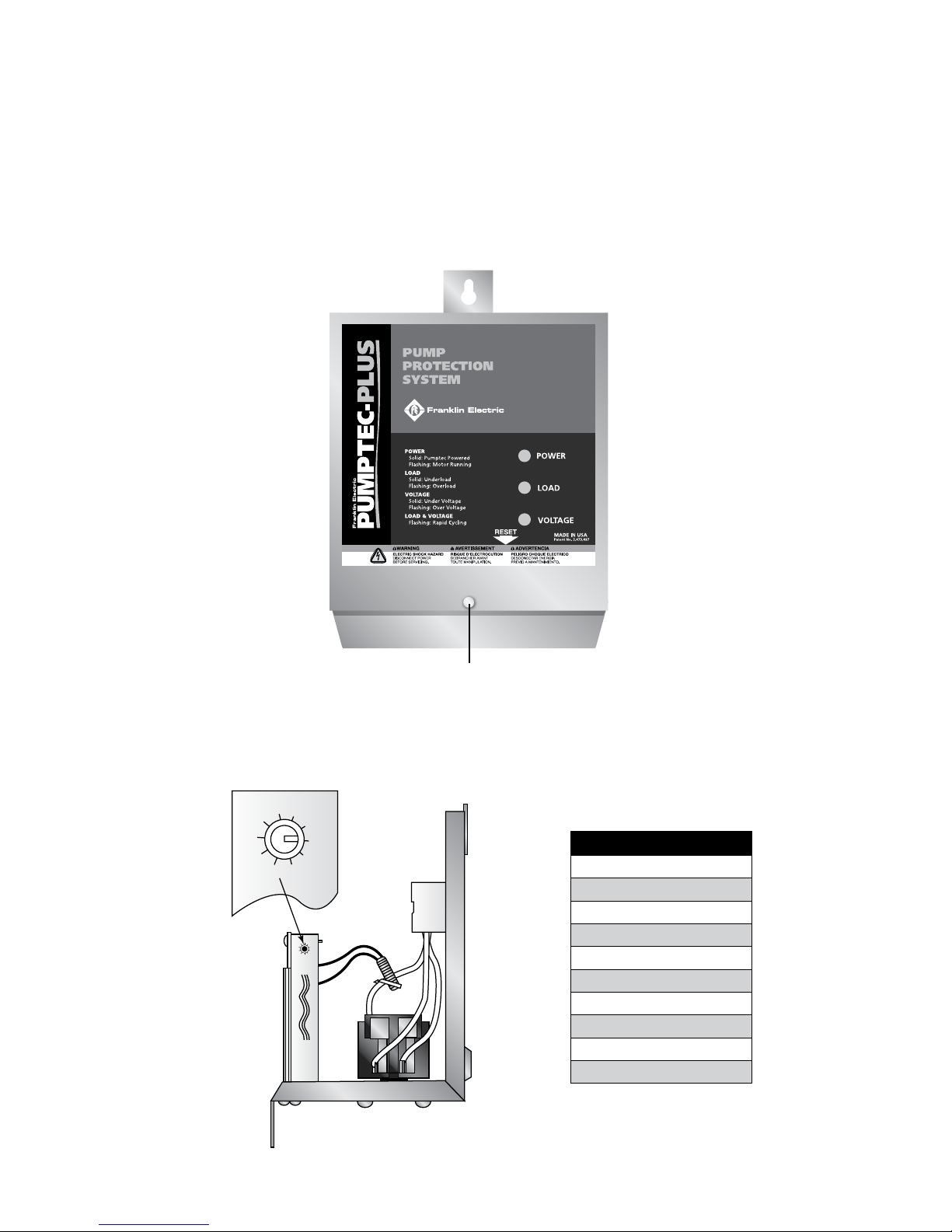
1. Remove Cover
Remove the Pumptec-Plus cover by removing the cover screw and sliding the cover up. Place
cover in a safe location.
FRONT COVER SCREW
2. Set the Timer Switch
Set the automatic timer switch to the desired reset time. This will determine the time after an
underload trip condition (dry well condition) has occurred until the Pumptec-Plus will try to restart
the motor.
Timer Switch Settings
0) Manual Reset
1) 1 Minute
2) 2 Minutes
3) 4 Minutes
4) 8 Minutes
5) 16 Minutes
6) 32 Minutes
7) 1 Hour 4 Minutes
8) 2 Hours 8 Minutes
9) 4 Hours 16 Minutes
5
PUMPTEC-PLUS Pump Protection System
MOUNTING SURFACE
PRESSURE
SWITCH
OR OTHER
CONTROL
FUSED
DISCONNECT
OR
CIRCUIT
BREAKER
GND
GND
GND
L2
L2
M1
M2
L1
L1
GND
GND L2 L1
L2 L1
PUMP &
MOTOR
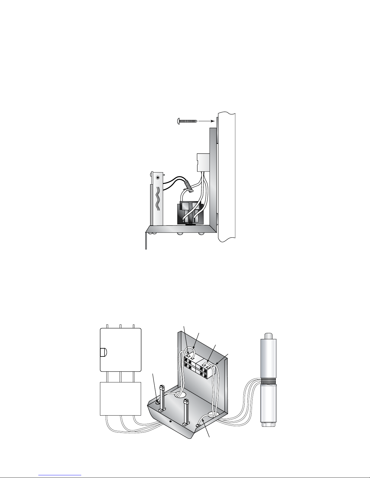
3. Mount the Unit
Mount the Pumptec-Plus unit in a location convenient for wiring. Avoid direct sunlight, rain or snow.
DISCONNECT POWER AT THE MAIN PANEL before installing, wiring
!
s WARNING
WARNING
or servicing the Pumptec-Plus unit. Serious or fatal shock may occur if
power is not disconnected.
SCREW
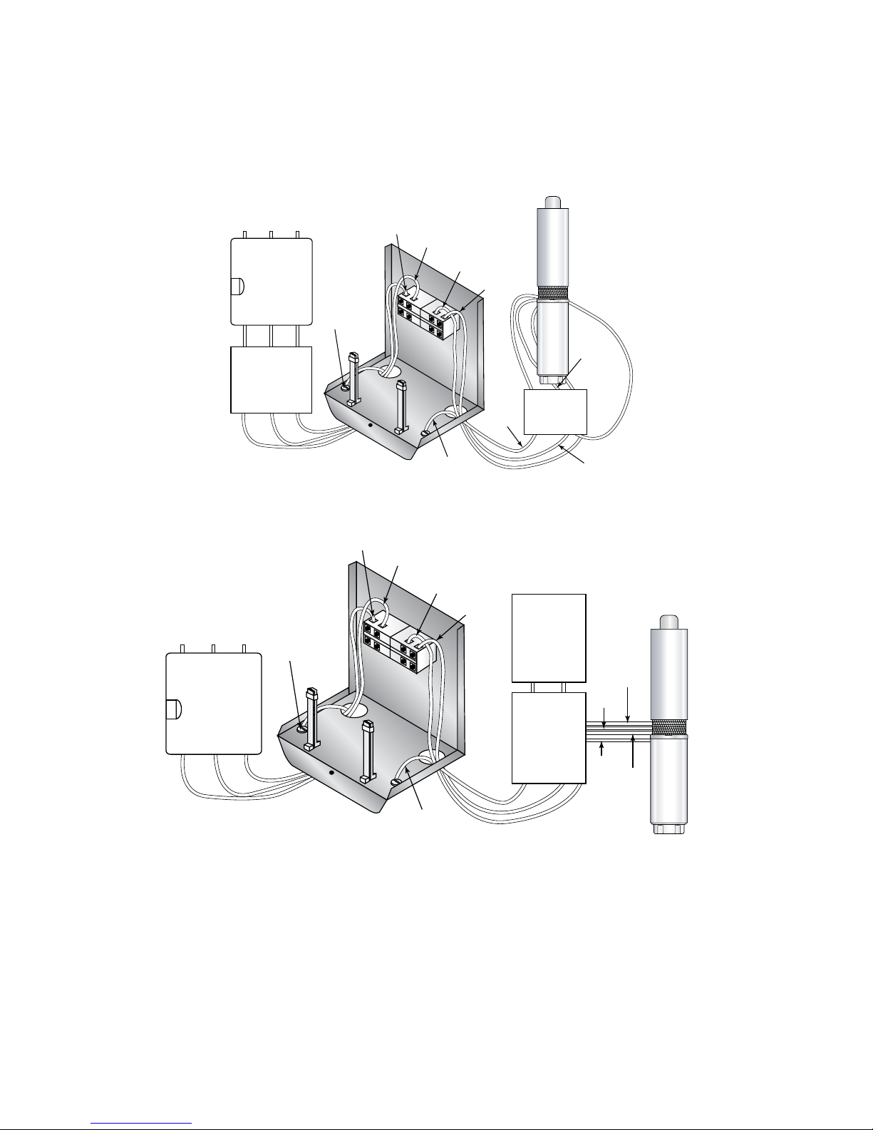
4. Connect Power and Motor
Check to make sure the 230 Volt power has been disconnected. Connect Pumptec-Plus unit to the pump
motor and the 230 Volt AC line according to one of the two- or three-wire installation drawings below.
Pumptec-Plus may be wired into the circuit before or after the pressure switch, oat switch or other
system control switch.
6
2-WIRE INSTALLATION
PUMPTEC-PLUS Pump Protection System
FUSED
DISCONNECT
OR
CIRCUIT
BREAKER
GND
GND
GND
GND
L2
L2
L2
M1
M2
L1
L1
L1
GND
L2 L1
RED
PUMP &
MOTOR
BLK
DELUXE
CONTROL
BOX
PRESSURE
SWITCH
OR OTHER
CONTROL
SW2
L2
L2
YEL
M2
PRESSURE
SWITCH
OR OTHER
CONTROL
FUSED
DISCONNECT
OR
CIRCUIT
BREAKER
GND
GND
GND
GND
L2
L2
M1
M2
M2
L1
L1
GND
GND M2 M1
M1
L2 L1
RED
PUMP &
MOTOR
BLK
YEL
CONTROL
BOX
L1
L2
3-WIRE INSTALLATION
3-WIRE INSTALLATION WITH DELUXE CONTROL BOX
5. Replace Cover
Replace cover and secure with screw provided.
6. Apply Power
Once power is applied the Pumptec-Plus unit should trip, indicating an overload condition
(blinking yellow light) when the pump tries to run. This is normal and is a reminder that PumptecPlus requires calibration.
NOTE: Some 1/2 hp motors will not trip in an overload condition upon the initial application of
power. The green light will blink instead. This is also a normal condition. Proceed to step 7.
7

PUMPTEC-PLUS Pump Protection System
7. Calibrate
Before the Pumptec-Plus unit is ready for use it MUST BE CALIBRATED. The calibration
procedure is quick and as simple as taking a snapshot.
Calibration may be performed as many times as desired by following steps A, B, and C below.
A. Press and hold in the reset button on the bottom of the Pumptec-Plus enclosure until the
green, yellow, and red lights blink alternately. This should take approximately 10 seconds.
You will hear the Pumptec-Plus contactor engage and the motor should start. Release the
reset button. Steps B and C must be completed within three minutes or the calibration
procedure will be aborted.
B. Verify that the pump system is running normally (i.e. the system is pumping water and the
motor current is normal). Try to achieve maximum water ow rate. Calibration on a fully
recovered well is recommended.
C. Briey press the reset switch again and then release it. You have just taken a snapshot
of the motor load. All indicator lights will go o. After 2 to 3 seconds, the green light will
start ashing, indicating the system is running normally and calibration is complete. Over/
underload trips will occur at 125% and 75% of the snapshot load.
NOTE: Continuous memory holds calibration snapshot even if power is absent.
!
s WARNING
CAUTION
Pumptec-Plus should only be calibrated by qualied service personnel.
Calibration on a faulty pump system will not provide protection.
Operation
Under normal operating conditions, Pumptec-Plus requires no special attention. The power line
voltage and motor power draw are continuously measured. If a fault condition is detected, an
indication is given by a light on the front panel and the motor is disconnected from the power line.
Pumptec-Plus measures the actual motor power (Watts), not motor amps or power factor. The
motor power draw at the moment of calibration is permanently memorized by Pumptec-Plus. If the
motor power draw diers from the memorized calibration power by more than ± 25%, PumptecPlus will turn o the pump motor. It is very important to make sure the pump system is running
normally during the calibration process.
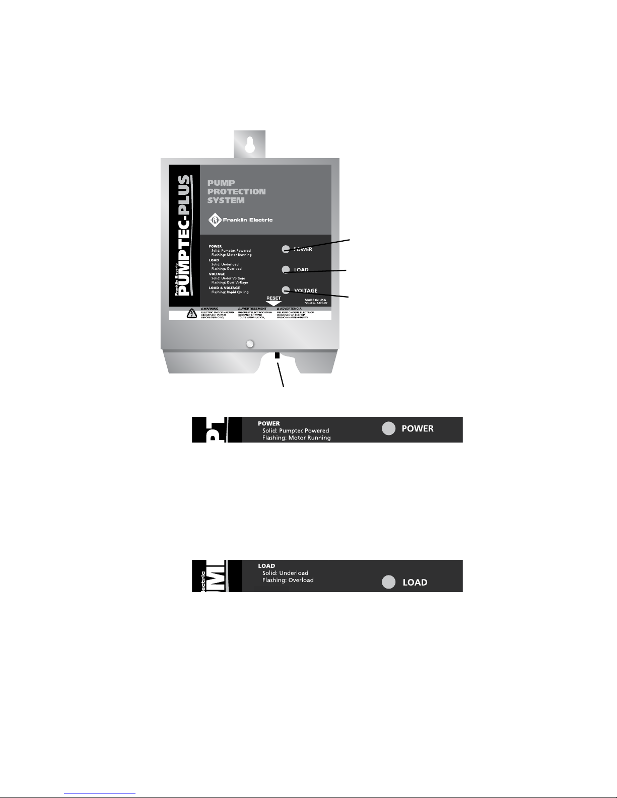
There are three indicator lights (A, B, and C) visible through the front cover. Each light is a dierent
color and each has a special meaning. Also, on the bottom of the unit enclosure is a reset button
(D). The purpose of each light and the operation of the reset button are described on page 5.
8
PUMPTEC-PLUS Pump Protection System
Operation cont.
A. GREEN LIGHT
B. YELLOW LIGHT
C. RED LIGHT
D. RESET BUTTON
A. Green Light
The green light (A) indicates that the status of the pump system is normal.
A SOLID GREEN LIGHT indicates that Pumptec-Plus has power and the contactor to the motor
is closed but the motor is not running. This may happen when the pressure switch is wired in
down-line from Pumptec-Plus and the switch is open. Pumptec-Plus is waiting for the pressure
switch to close.
A FLASHING GREEN LIGHT indicates the pump motor is running normally and drawing the
correct amount of power.
B. Yellow Light
The yellow light (B) indicates that a load fault has occurred.
A SOLID YELLOW LIGHT indicates an underload fault occurred. The Pumptec-Plus automatic
restart timer will restart the motor in accordance with the position of the automatic restart timer
switch setting. The switch should be set at the time of installation (refer to step 2). If set in the
manual position, Pumptec-Plus must be reset manually by pushing the RESET BUTTON (D).
A FLASHING YELLOW LIGHT indicates an overload condition occurred. This means that the pump
system power draw was greater than the normal operating power (calibration) by more than 25%
for more than 2.5 seconds. Pumptec-Plus will not run the pump system again until the RESET
BUTTON (D) is pressed.
9
PUMPTEC-PLUS Pump Protection System
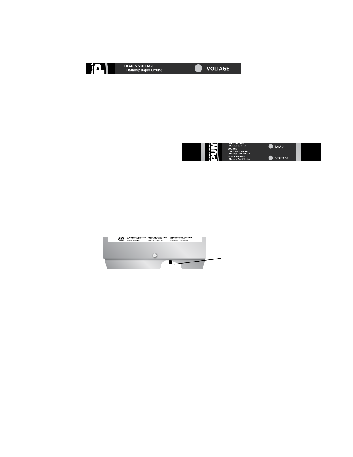
C. Red Light
The red light (C) indicates a line voltage fault occurred and Pumptec-Plus has turned o the pump motor.
A SOLID RED LIGHT indicates an under voltage condition (line< 207 VAC) existed for more than 2.5
seconds. Pumptec-Plus will automatically try to reset the motor within two minutes. The RESET BUTTON
(D) may also be pressed to clear this condition.
A FLASHING RED LIGHT indicates an over voltage condition (line> 253 VAC) has existed more than 2.5
seconds. Pumptec-Plus will automatically try to reset the motor within two minutes. The RESET BUTTON
(D) may also be pressed to clear this condition.
B & C. Red and Yellow Flashing Lights
The red light (C) indicates a line voltage fault occurred and Pumptec-Plus has turned o the pump motor.
A SOLID RED LIGHT indicates an under voltage condition (line< 207 VAC) existed for more than 2.5
seconds. Pumptec-Plus will automatically try to reset the motor within two minutes. The RESET BUTTON
(D) may also be pressed to clear this condition.
A FLASHING RED LIGHT indicates an over voltage condition (line> 253 VAC) has existed more than 2.5
seconds. Pumptec-Plus will automatically try to reset the motor within two minutes. The RESET BUTTON
(D) may also be pressed to clear this condition.
RESET BUTTON
D. Reset Button
The reset button is used to restart the Pumptec-Plus from a tripped condition. Pressing the reset button
for less than ten seconds has no eect on the calibration. Simply press and release the button. The unit
will reset.
Pressing the reset button for more than 10 seconds will cause the unit to go into the calibration mode. A
rotating light sequence from green to yellow to red will begin. At this point, the contactor closes and the
motor will start to run. The unit will stay in the calibration mode for 3 minutes or until the reset button is
pressed again.
If after three minutes the reset button is not pressed, the unit will revert back to its normal running mode,
making no changes to the calibration.
Pressing the reset button before the three minute period expires will cause the unit to recalibrate to the
motor load present at the time the reset button is pressed the second time.
10

PUMPTEC-PLUS Pump Protection System
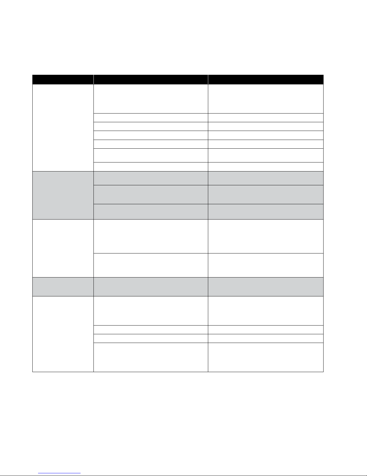
Troubleshooting During Installation
Symptom Possible Cause Solution
Check wiring. Power supply voltage should be applied
Unit Appears Dead
(No Lights)
Unit Needs to Be Calibrated
Flashing Yellow Light
Flashing Yellow Light
During Calibration
Flashing Red
and Yellow Lights
Flashing Red Light
Solid Red Light
*Report high or low line voltage to the power company.
No Power to Unit
Miscalibrated
Two-Wire Motor
Power Interruptor
Float Switch
High Line Voltage
Unloaded Generator
Low Line Voltage The line voltage is below 207 Volts. Check line voltage.
Loose Connections
Loaded Generator
to the L1 and L2 terminals of the Pumptec-Plus. In some
installations, the pressure switch or other control device
is wired to the input of the Pumptec-Plus. Make sure this
switch is closed.
Pumptec-Plus is calibrated at the factory so that it will
overload on most pump systems when the unit is rst
installed. This overload condition is a reminder that the
Pumptec-Plus unit requires calibration before use. See
step 7 of the installation instructions.
Pumptec-Plus should be calibrated on a fully recovered
well with maximum water ow. Flow restrictors are not
recommended.
Step C of the calibration instructions indicates that a
ashing green light condition will occur 2 to 3 seconds
after taking the snapshot of the motor load. On some two-
wire motors, the yellow light will ash instead of the green
light. Press and release the reset button. The green should
start ashing.
During the installation of Pumptec-Plus, power may be
switched on and o several times. If power is cycled more
than four times within a minute, Pumptec-Plus will trip on
rapid cycle. Press and release the reset button to restart
the unit.
A bobbing oat switch may cause the unit to detect
a rapid cycle condition on any motor or an overload
condition on two-wire motors. Try to reduce water
splashing or use a dierent switch.
The line voltage is over 253 Volts.
Check line voltage.*
If you are using a generator, the line voltage may become
too high when the generator unloads. Pumptec-Plus will
not allow the motor to turn on again until the line voltage
returns to normal. Over voltage trips will also occur if the
line frequency drops too far below 60 Hz.
Check for loose connections which may cause
voltage drops.
If you are using a generator, the line voltage may become
too low when the generator loads. Pumptec-Plus will trip
on under voltage if the generator voltage drops below 207
Volts for more than 2.5 seconds. Under voltage trips will
also occur if the line frequency rises too far above 60 Hz.
11
PUMPTEC-PLUS Pump Protection System
Troubleshooting After Installation
Symptom Possible Cause Solution
Wait for the automatic restart timer to time out. During
the time out period the well should recover and ll with
water. If the automatic reset timer switch is set to the
manual position, then the reset button must be pressed to
reactivate the unit.
Machine gun rapid cycling can cause an underload
condition. See ashing red and yellow lights section below.
Repair or replace pump motor. Pump may be sand or mud
locked.
A bobbing oat switch can cause two-wire motors to stall.
Arrange plumbing to avoid splashing water. Replace oat
switch.
Check insulation resistance on motor and control box
cable.
Step C of the calibration instructions indicates that a
ashing green light condition will occur 2 to 3 seconds
after taking the Snapshot of the motor load. On some two-
wire motors, the yellow light will ash instead of the green
light. Press and release the reset button. The green should
start ashing.
Check for excessive voltage drops in the system electrical
connections (i.e. circuit breakers, fuse clips, pressure
switch, and Pumptec-Plus L1 and L2 terminals). Repair
connections.
The line voltage is over 253 Volts. Check line voltage.*
The Pumptec-Plus will try to restart the motor every two
minutes until line voltage is normal.
The most common cause for the rapid cycle condition is
a waterlogged tank. Check for a ruptured bladder in the
water tank. Check the air volume control or snifter valve for
proper operation. Check the setting on the pressure switch
and examine for defects.
Press and release the reset button to restart the unit. A
bobbing oat switch may cause the unit to detect a rapid
cycle condition on any motor or an overload condition on
two-wire motors. Try to reduce water splashing or use a
dierent switch.
Solid Yellow Light
Flashing Yellow Light
Solid Red Light
Flashing Red Light High Line Voltage
Flashing Red And
Yellow Lights
*Report high or low line voltage to the power company.
Blocked Discharge Remove blockage in plumbing.
Severe Rapid Cycling
Low Line Voltage
Loose Connections
Leaky Well System Replace damaged pipes or repair leaks.
Stuck Check Valve Failed valve will not hold pressure. Replace valve.
Dry Well
Blocked Intake Clean or replace pump intake screen.
Check Valve Replace check valve.
Broken Shaft Replace broken parts.
Worn Pump Replace worn pump parts and recalibrate.
Stalled Motor
Float Switch
Ground Fault
Rapid Cycle
Float Switch
12

STANDARD LIMITED WARRANTY
Except as set forth in an Extended Warranty, for twelve (12) months from the date of installation, but in no event more than twenty-four
(24) months from the date of manufacture, Franklin hereby warrants to the purchaser (“Purchaser”) of Franklin’s products that, for the
applicable warranty period, the products purchased will (i) be free from defects in workmanship and material at the time of shipment, (ii)
perform consistently with samples previously supplied and (iii) conform to the specications published or agreed to in writing between the
purchaser and Franklin. This limited warranty extends only to products purchased directly from Franklin. If a product is purchased other
than from a distributor or directly from Franklin, such product must be installed by a Franklin Certied Installer for this limited warranty to
apply. This limited warranty is not assignable or transferable to any subsequent purchaser or user.
a. THIS LIMITED WARRANTY IS IN LIEU OF ALL OTHER WARRANTIES, WRITTEN OR ORAL, STATUTORY, EXPRESS, OR IMPLIED,
INCLUDING ANY WARRANTY OF MERCHANTABILITY OR FITNESS FOR A PARTICULAR PURPOSE. PURCHASER’S SOLE AND
EXCLUSIVE REMEDY
FOR FRANKLIN’S BREACH OF ITS OBLIGATIONS HEREUNDER, INCLUDING BREACH OF ANY EXPRESS OR IMPLIED WARRANTY OR
OTHERWISE, UNLESS PROVIDED ON THE FACE HEREOF OR IN A WRITTEN INSTRUMENT MADE PART OF THIS LIMITED WARRANTY,
SHALL BE FOR THE PURCHASE PRICE PAID TO FRANKLIN FOR THE NONCONFORMING OR DEFECTIVE PRODUCT OR FOR THE
REPAIR OR REPLACEMENT OF NONCONFORMING OR DEFECTIVE PRODUCT, AT FRANKLIN’S ELECTION. ANY FRANKLIN PRODUCT
WHICH FRANKLIN DETERMINES TO BE DEFECTIVE WITHIN THE WARRANTY PERIOD SHALL BE, AT FRANKLIN’S SOLE OPTION,
REPAIRED, REPLACED, OR A REFUND OF THE PURCHASE PRICE PAID. Some states do not allow limitations on how long an implied
warranty lasts, therefore, the limitations and exclusions relating to the products may not apply.
b. WITHOUT LIMITING THE GENERALITY OF THE EXCLUSIONS OF THIS LIMITED WARRANTY, FRANKLIN SHALL NOT BE LIABLE TO
THE PURCHASER OR ANY THIRD PARTY FOR ANY AND ALL (i) INCIDENTAL EXPENSES OR OTHER CHARGES, COSTS, EXPENSES
(INCLUDING COSTS OF INSPECTION, TESTING, STORAGE, OR TRANSPORTATION) OR (ii) DAMAGES, INCLUDING CONSEQUENTIAL,
SPECIAL DAMAGES, PUNITIVE OR INDIRECT DAMAGES, INCLUDING, WITHOUT LIMITATION, LOST PROFITS, LOST TIME AND
LOST BUSINESS OPPORTUNITIES, REGARDLESS OF WHETHER FRANKLIN IS OR IS SHOWN TO BE AT FAULT, AND REGARDLESS
OF WHETHER THERE IS OR THERE IS SHOWN TO HAVE BEEN A DEFECT IN MATERIALS OR WORKMANSHIP, NEGLIGENCE IN
MANUFACTURE OR DESIGN, OR A FAILURE TO WARN.
c. Franklin’s liability arising out of the sale or delivery of its products, or their use, whether based upon warranty contract, negligence, or
otherwise, shall not in any case exceed the cost of repair or replacement of the product and, upon expiration of any applicable warranty
period, any and all such liability shall terminate.
d. Without limiting the generality of the exclusions of this limited warranty, Franklin does not warrant the adequacy of any specications
provided directly or indirectly by a purchaser or that Franklin’s products will perform in accordance with such specications. This limited
warranty does not apply to any products that have been subject to misuse (including use in a manner inconsistent with the design of
the product), abuse, neglect, accident or improper installation or maintenance, or to products that have been altered or repaired by any
person or entity other than Franklin or its authorized representatives.
e. Unless otherwise specied in an Extended Warranty authorized by Franklin for a specic product or product line, this limited warranty
does not apply to performance caused by abrasive materials, corrosion due to aggressive conditions or improper voltage supply.
f. With respect to motors and pumps, the following conditions automatically void this limited warranty:
1. Mud or sand deposits which indicate that the motor has been submerged in mud or sand.
2. Physical damage as evidenced by bent shaft, broken or chipped castings, or broken or bent thrust parts.
3. Sand damage as indicated by abrasive wear of motor seals or splines.
4. Lightning damage (often referred to as high voltage surge damage).
5. Electrical failures due to the use of non-approved overload protection.
6. Unauthorized disassembly.

NOTES:

NOTES:
 Loading...