

Page 1

Istruzioni per l’uso e l’installazione
Instructions for use and installation
Mode d’emploi et installation
Bedienungsanleitung und Einrichtung
Kullan
ım ve montaj talimatları
GB
IT
FR
DE
TR
Cappa
Cooker Hood
Hotte de Cuisine
Dunstabzugshaube
Davlumbaz
FTU 3807 W
Page 2

IT
Libretto di Istruzioni
INDICE
CONSIGLI E SUGGERIMENTI ..............................................................................................................................................7
CARATTERISTICHE..............................................................................................................................................................8
INSTALLAZIONE....................................................................................................................................................................9
USO......................................................................................................................................................................................13
MANUTENZIONE.................................................................................................................................................................14
2
2
Page 3

EN
Instructions Manual
INDEX
RECOMMENDATIONS AND SUGGESTIONS....................................................................................................................16
CHARACTERISTICS............................................................................................................................................................17
INSTALLATION ....................................................................................................................................................................18
USE.......................................................................................................................................................................................22
MAINTENANCE....................................................................................................................................................................23
3
3
Page 4

FR
Manuel d’Instructions
SOMMAIRE
CONSEILS ET SUGGESTIONS ..........................................................................................................................................25
CARACTERISTIQUES.........................................................................................................................................................26
INSTALLATION ....................................................................................................................................................................27
UTILISATION........................................................................................................................................................................31
ENTRETIEN..........................................................................................................................................................................32
4
4
Page 5

DE
Bedienungsanleitung
INHALTSVERZEICHNIS
EMPFEHLUNGEN UND HINWEISE....................................................................................................................................34
CHARAKTERISTIKEN..........................................................................................................................................................35
MONTAGE............................................................................................................................................................................36
BEDIENUNG.........................................................................................................................................................................40
WARTUNG............................................................................................................................................................................41
5
5
Page 6

TR
Kullanim Kilavuku
IÇERIKLER
TAVSIYELER VE ÖNERILER ..............................................................................................................................................43
ÖZELLIKLER........................................................................................................................................................................44
MONTAJ...............................................................................................................................................................................45
KULLANIM............................................................................................................................................................................49
BAKIM...................................................................................................................................................................................50
6
6
Page 7

IT
650 mm min.
CONSIGLI E SUGGERIMENTI
INSTALLAZIONE
• Il produttore declina qualsiasi responsabilità per danni dovuti
ad installazione non corretta o non conforme alle regole
dell’arte.
• La distanza minima di sicurezza tra il Piano di cottura e la
Cappa deve essere di 650 mm.
• Verificare che la tensione di rete corrisponda a quella riportata
nella targhetta posta all’interno della Cappa.
• Per Apparecchi in Classe Ia accertarsi che l’impianto elettrico
domestico garantisca un corretto scarico a terra.
• Collegare la Cappa all’uscita dell’aria aspirata con tubazione di
diametro pari o superiore a 120 mm. Il percorso della tubazione deve essere il più breve possibile.
• Non collegare la Cappa a condotti di scarico dei fumi prodotti
da combustione (caldaie, caminetti, ecc.).
• Nel caso in cui nella stanza vengano utilizzati sia la Cappa che
apparecchi non azionati da energia elettrica (ad esempio apparecchi utilizzatori di gas), si deve provvedere ad una aerazione
sufficiente dell’ambiente. Se la cucina ne fosse sprovvista, praticare un’apertura che comunichi con l’esterno, per garantire il
richiamo d’aria pulita.
USO
• La Cappa è stata progettata esclusivamente per uso domestico,
per abbattere gli odori della cucina.
• Non fare mai uso improprio della Cappa.
• Non lasciare fiamme libere a forte intensità sotto la Cappa in
funzione.
• Regolare sempre le fiamme in modo da evitare una evidente
fuoriuscita laterale delle stesse rispetto al fondo delle pentole.
• Controllare le friggitrici durante l’uso: l’olio surriscaldato potrebbe infiammarsi.
• La Cappa non deve essere utilizzata da bambini o persone non
abilitate all’uso corretto.
MANUTENZIONE
• Prima di procedere a qualsiasi operazione di manutenzione,
disinserire la Cappa togliendo la spina elettrica o spegnendo
l’interruttore generale.
• Effettuare una scrupolosa e tempestiva manutenzione dei Filtri
secondo gli intervalli consigliati.
• Per la pulizia delle superfici della Cappa è sufficiente utilizzare
un panno umido e detersivo liquido neutro.
7
7
Page 8
IT
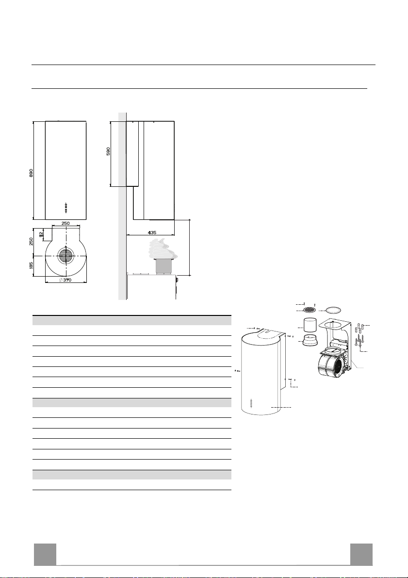
CARATTERISTICHE
Ingombro
650 min.
Componenti
Rif. Q.tà Componenti di Prodotto
1 1 Corpo Cappa com pleto di: Com andi, Luce, Filtri
3 1 Supporto Cappa completo di Gruppo Aspi ratore
7 1 Tubo PVC
8 1 Griglia Direzionata ø 125 mm
8c 1 Riduzione uscita aria ø 120 mm
9 1 Flangia di riduzione ø 150-120 mm
Rif. Q.tà Componenti di Installazione
11 4 Tasselli ø 10
12a 4 Viti 5 x 70
12b 4 Viti M4 x 15
12e 2 Viti 2,9 x 9,5
13 4 Tappo viti M4
Q.tà Documentazione
1 Libretto Istruzioni
12e
8
8c
13
7
9
12b
1
11
12a
3
8
8
Page 9
IT
l
i
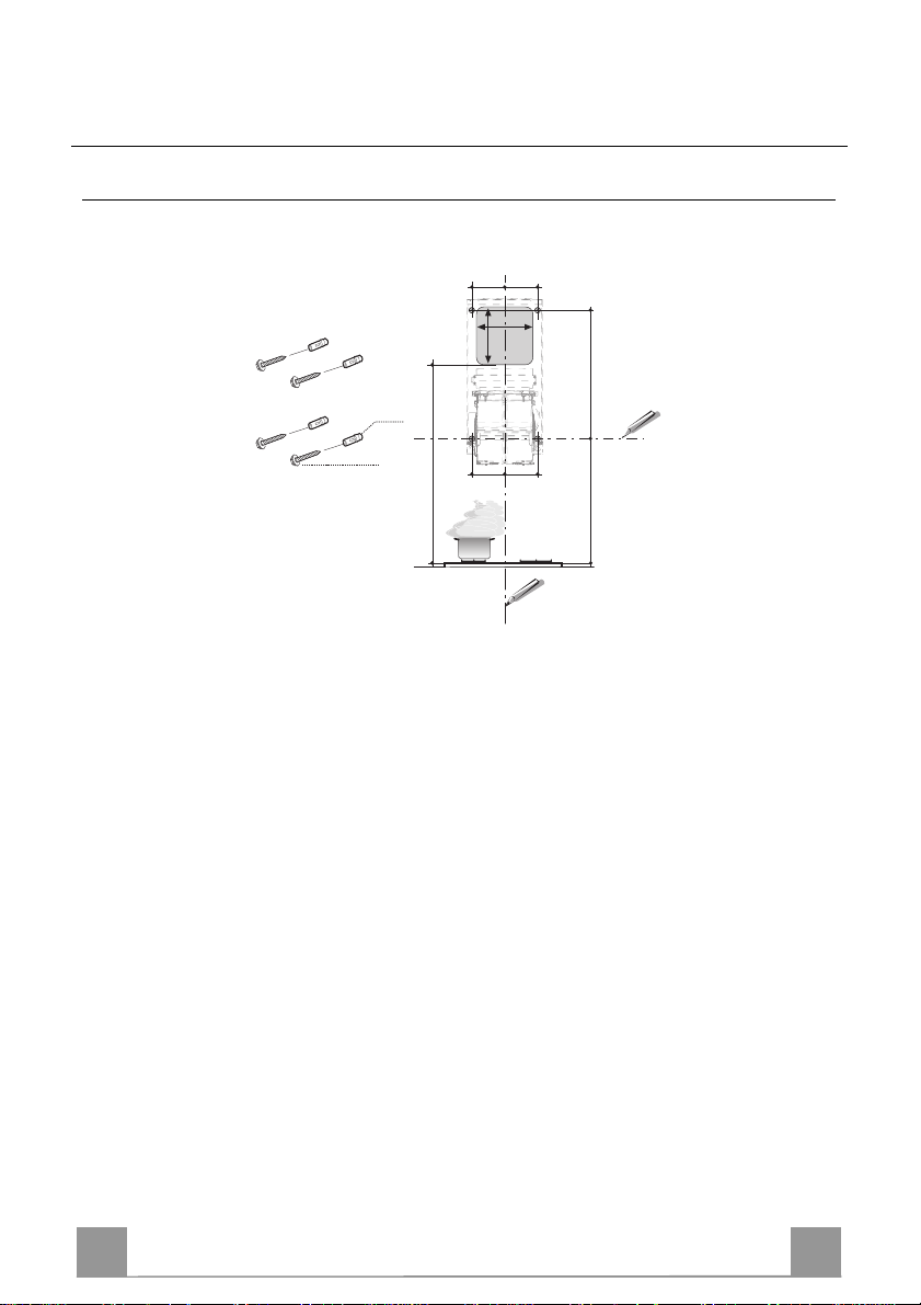
INSTALLAZIONE
Foratura Parete
Data la complessità dell’installazione si raccomanda di effettuarla minimo in due persone.
11
12a
Tracciare sulla Parete:
• una linea Verticale fino al soffitto o al limite superiore, al centro della zona prevista per i
montaggio della Cappa;
• una linea Orizzontale a: 1150 mm min. sopra il Piano di Cottura;
• Segnare come indicato, un punto di riferimento a 100 mm sulla destra della linea verticale d
riferimento.
• Ripetere questa operazione dalla parte opposta, verificandone il livellamento.
• Segnare come indicato, un punto di riferimento a 390 mm sopra la linea orizzontale di riferimento, e a 100 mm sulla destra della linea verticale di riferimento.
• Ripetere questa operazione dalla parte opposta, verificandone il livellamento.
• Forare ø 10 mm i punti segnati.
• Inserire i tasselli 11 nei fori.
1340
100 100
100 100
170
175
1150 390
9
9
Page 10
IT 110
3
12a
ø 150
ø 120
9
8c
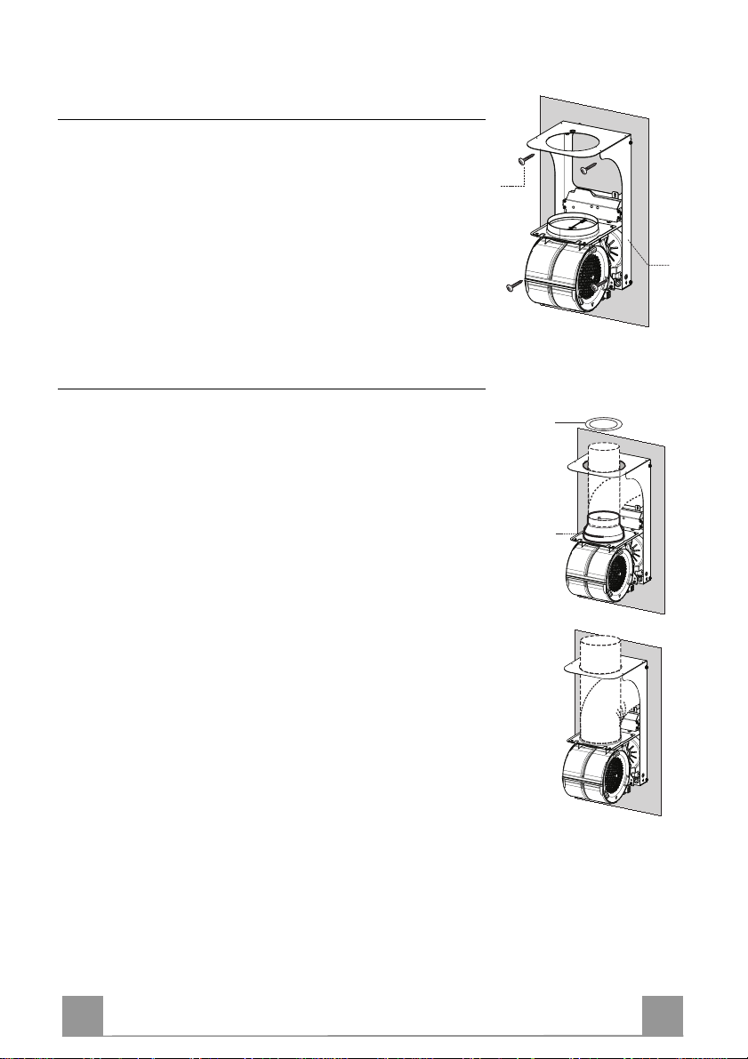
Montaggio Supporto Cappa
• Appoggiare il Supporto Cappa 3 al muro facendo coincidere i
fori del supporto con quelli fatti al muro.
• Bloccare il supporto al muro utilizzando le quattro viti 12a (5 x
70) in dotazione.
• Prima di serrare definitivamente le viti livellare il supporto,
quindi bloccare definitivamente le viti.
Connessione Uscita Aria Versione Aspirante
Per installazione in Versione Aspirante collegare la Cappa alla
tubazione di uscita per mezzo di un tubo rigido o flessibile di ø
150 o 120 mm, la cui scelta è lasciata all'installatore. Il tubo può
uscire sia dalla parte superiore che posteriore della cappa.
USCITA POSTERIORE
• Si ricorda che per effettuare il foro di evacuazione va seguito
lo schema riportato nel paragrafo foratura parete.
• Per collegamento con tubo ø120 mm, inserire la Flangia di riduzione 9 sull'Uscita del Corpo Cappa.
• Fissare il tubo con adeguate fascette stringitubo. Il materiale
occorrente non è in dotazione.
• Togliere eventuali Filtri Antiodore al Carbone attivo.
USCITA SUPERIORE
• Per collegamento con tubo ø 150 mm, collegare la Cappa alla
tubazione di uscita per mezzo di un tubo rigido o flessibile.
• Per collegamento con tubo ø120 mm, inserire la Flangia di riduzione 9 sull'Uscita del Corpo Cappa.
• Avvitare la riduzione uscita aria 8c sul foro di uscita del supporto cappa utilizzando le viti in dotazione.
• Collegare la Cappa alla tubazione di uscita per mezzo di un
tubo rigido o flessibile.
• Fissare il tubo con adeguate fascette stringitubo. Il materiale
occorrente non è in dotazione.
• Togliere eventuali Filtri Antiodore al Carbone attivo.
Page 11
IT 111
12b
13
8
12e
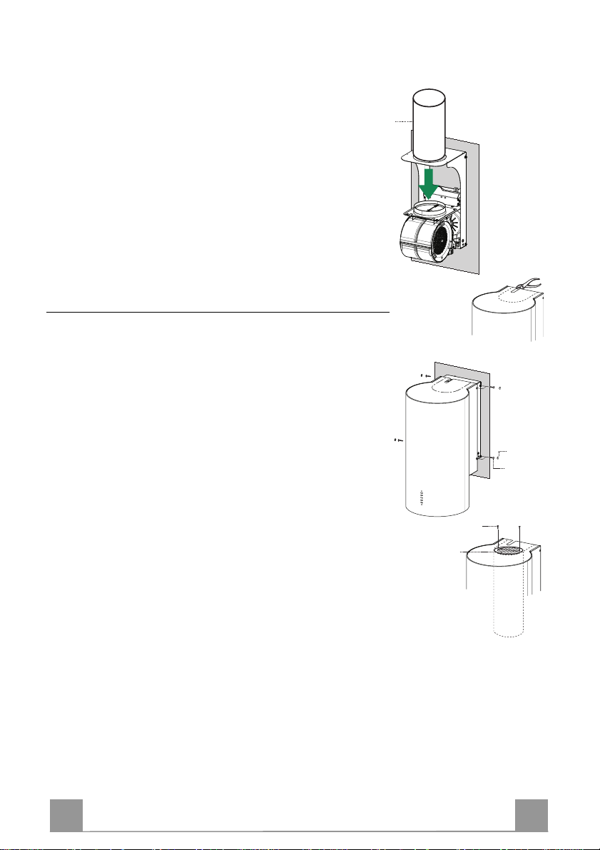
USCITA ARIA VERSIONE FILTRANTE
• Inserire il tubo in pvc 7 in dotazione sull’uscita del Corpo
Cappa
Montaggio corpo cappa
Versione Aspirante
• Nel caso in cui sia stata scelta l’uscita dell’aria sulla parte superiore della cappa si dovrà staccare il pezzo pretagliato.
• Appoggiare il corpo cappa al supporto e fissarlo lateralmente
utilizzando le quattro viti 12b.
• Coprire le sedi delle viti impiegando i tappi 13 in dotazione.
Versione Filtrante
• Staccare il pezzo pretagliato.
• Appoggiare il corpo cappa al supporto e fissarlo lateralmente
utilizzando le quattro viti 12b.
• Coprire le sedi delle viti impiegando i tappi 13 in dotazione.
• Posizionare la Griglia direzionata 8 sul Tubo e verificare la sua
corretta installazione.
• Avvitare la Griglia direzionata 8 con la Viti 12e in dotazione.
• Assicurarsi della presenza dei Filtri antiodore al Carbone attivo.
ø 150
7
Page 12
IT 112
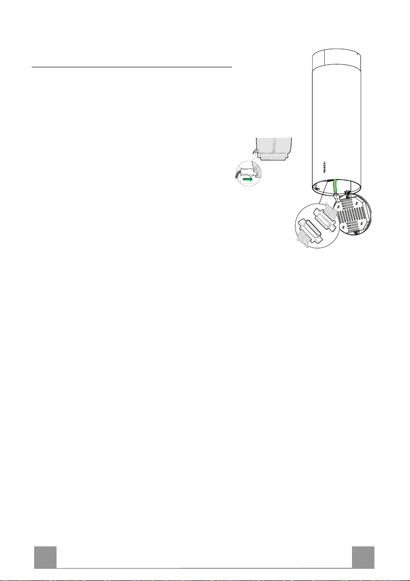
Connessione elettrica
• Collegare la Cappa all’Alimentazione di Rete interponendo un Interruttore bipolare con apertura dei
contatti di almeno 3 mm.
• Aprire il gruppo illuminazione tirandolo sull’apposita
intacca
• Togliere il Filtro , spingendolo verso la parte posteriore del gruppo e tirando contemporaneamente verso
il basso.
• Assicurarsi che il connettore del Cavo di alimentazione sia correttamente inserito nella presa
dell’Aspiratore
• Collegare il connettore dei Comandi Cmd.
• Collegare il connettore dei Faretti Lux alla presa
predisposta dietro al coperchio del gruppo illuminazione.
• Rimontare il Filtro Antigrasso e successivamente il
gruppo illuminazione.
Lux
Cmd
Page 13
IT 113
USO
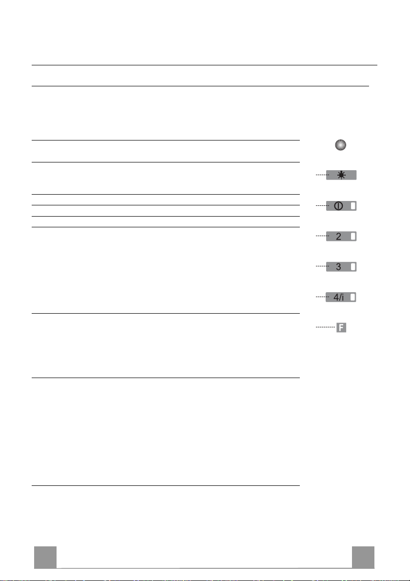
Quadro comandi
La cappa può essere accesa direttamente alla velocità desiderata, premendo
il relativo tasto senza passare per il tasto 0/1 motore.
TASTO LED FUNZIONI
L - Accende e spegne l’impianto di
illuminazione.
T1 0/1 Motore Fisso Prima velocità.
Spegne la cappa se premuto per
circa 1”.
T2 Velocità Fisso Seconda velocità.
T3 Velocità Fisso Terza velocità.
T4 Velocità Fisso Velocità massima.
Lampeggiante Velocità intensiva.
Adatta a fronteggiare le massime
emissioni di fumi di cottura. Si attiva premendo per circa 2” il tasto. Si
spegne automaticamente dopo 10
minuti dall’entrata in funzione. Può
essere disinserita manualmente
premendo qualsiasi tasto velocità.
S1 Led Fisso Segnala l’allarme saturazione Filtri
Antigrasso Metallici e la necessità
di lavarli. L’allarme entra in funzione dopo 100 ore di lavoro effettivo della Cappa. (Reset vedi parag. Manutenzione)
Lampeggiante Segnala, quando è attivato,
l’allarme saturazione Filtro Antiodore al Carbone Attivo, che deve
essere sostituito; devono anche essere lavati i Filtri Antigrasso Metallici. L’allarme saturazione Filtro
Antiodore al Carbone Attivo entra
in funzione dopo 200 ore di lavoro
effettivo della Cappa. (Attivazione
e Reset vedi parag. Manutenzione)
L
T1
T2
T3
T4
S1
Page 14
IT 114
MANUTENZIONE
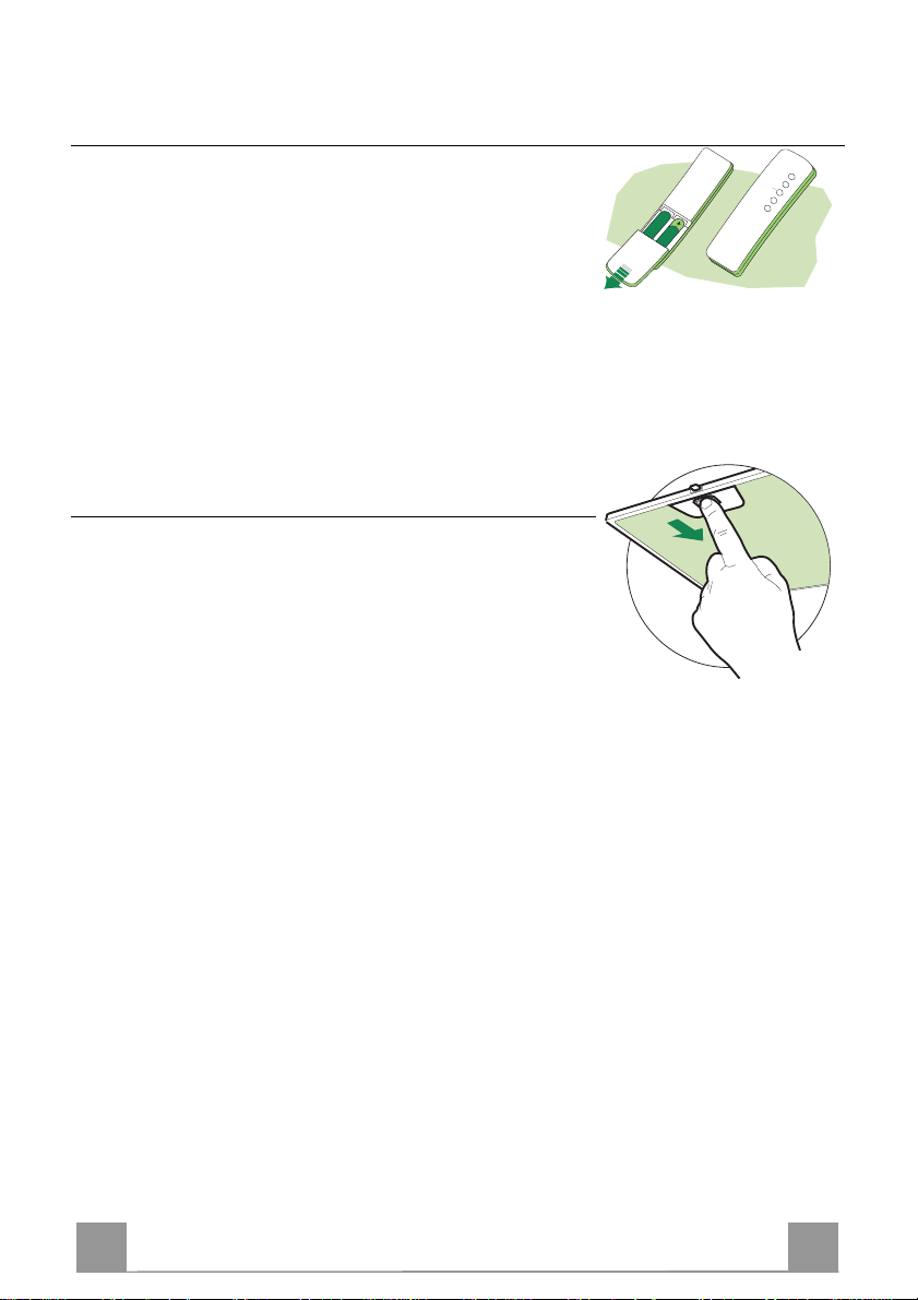
TELECOMANDO (OPZIONALE)
Questo apparecchio può essere comandato per mezzo di un telecomando, alimentato con pile alcaline zinco-carbone da 1,5 V del
tipo standard LR03-AAA.
• Non riporre il telecomando in prossimità di fonti di calore.
• Non disperdere le pile nell’ambiente, depositarle negli appositi
contenitori.
Filtri antigrasso metallici
PULIZIA FILTRI ANTIGRASSO ME TALLICI
Reset del segnale di allarme
• Spegnere le Luci e il Motore di aspirazione.
• Premere il tasto T3 per almeno 3 secondi, sino al lampeggio di
conferma dei led.
Pulizia Filtri
• Sono lavabili in lavastoviglie e necessitano di essere lavati
quando si accende il led S1 o al massimo ogni 2 mesi di utilizzo.
• Aprire il gruppo illuminazione tirandolo sull’apposita intacca.
• Togliere i Filtri uno alla volta, spingendoli verso la parte posteriore del gruppo e tirando contemporaneamente verso il basso.
• Lavare i Filtri evitando di piegarli, e lasciarli asciugare prima
di rimontarli.
• Rimontarli facendo attenzione a mantenere la maniglia verso la
parte visibile esterna.
• Richiudere il gruppo illuminazione.
Page 15
IT 115
Filtri antiodore al Carbone attivo (Versione Filtrante)
• Non è lavabile e non è rigenerabile, va sostituito quando il led S1 lampeggia o almeno ogni
4 mesi. La segnalazione di allarme si verifica solo quando é azionato il Motore di aspirazione.
Attivazione del segnale di allarme
• Nelle Cappe in Versione Filtrante, la segnalazione di Allarme saturazione Filtri va attivata al
momento dell’installazione o successivamente.
• Spegnere le Luci e il Motore di aspirazione.
• Scollegare la cappa dall’alimentazione di rete.
• Ripristinare il collegamento tenendo premuto il tasto T1.
• Rilasciare il tasto, tutti e cinque i led sono accesi in posizione fissa
• Entro 3 secondi premere il Tasto T1 sino al lampeggio di conferma dei Led T1 e T4:
• 2 lampeggi Led - Allarme saturazione Filtro antiodore al Carbone attivo ATTIVATO
• 1 lampeggio Led - Allarme saturazione Filtro antiodore al Carbone attivo DISATTIVATO
SOSTITUZIONE
Reset del segnale di allarme
• Spegnere le Luci e il Motore di aspirazione
• Premere il tasto T3 per almeno 4 secondi, sino al lampeggio di
conferma dei led.
Sostituzione Filtro
• Aprire il gruppo illuminazione tirando l’apposita intacca.
• Rimuovere il Filtro antigrasso
• Rimuovere il Filtro antiodore al Carbone attivo saturo, agendo
sugli appositi agganci.
• Montare il nuovo Filtro agganciandolo nella sua sede.
• Rimontare il Filtro antigrasso e il gruppo illuminazione.
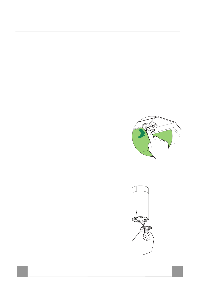
Illuminazione
SOSTITUZIONE LAMPADE
Lampade alogene da 20 W
• Estrarre la Lampada dal Supporto.
• Sostituirla con una nuova di uguali caratteristiche, facendo attenzione ad inserire correttamente i due spinotti nella sede del
Supporto.
Page 16
EN 116
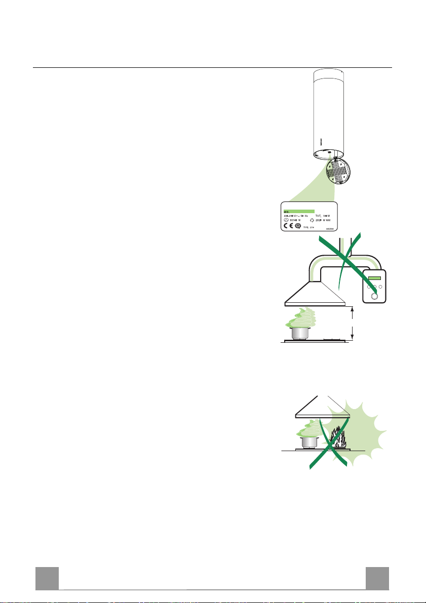
650 mm min.
RECOMMENDATIONS AND SUGGESTIONS
INSTALLATION
• The manufacturer will not be held liable for any damages resulting
from incorrect or improper installation.
• The mini mum safety distance between the c ooker top and the extractor hood is 650 mm.
• Check that the mains voltage corresponds to that indicated on the
rating plate fixed to the inside of the hood.
• For Class I appliances, check that the domestic power supply guaran tees adequate earthing.
Connect the extractor to the ex haust flue through a pi pe of minimum
diameter 120 mm. The route of the flue must be as short as possible.
• Do not conn ect the extractor ho od to exhaust ducts carrying comb ustion fumes (boilers, fireplaces, etc.).
• If the extractor is used in conjunction with non-el ectrical appliances
(e.g. gas burning appliances), a suffici ent degree of aeration must be
guaranteed in the room in order to prevent the backflow of exhaust
gas. The kitchen must have an opening communicating directl y with
the open air in order to guarantee the entry of clean air.
USE
• The extractor hood has been designed excl usi vely for domes tic use to
eliminate kitchen smells.
• Never use the hood f or purposes ot her than for which it h as ben designed.
• Never leave high naked flames under the hood when it is in operation.
• Adjust the flame intensity to direct it onto the bottom of the pan only,
making sure that it does not engulf the sides.
• Deep fat fryers must be continuously monitored during use: overheated oil can burst into flames.
• The hood sh ould not be used by chil dren or persons not ins tructed in
its correct use.
MAINTENANCE
• Switch off or unplug the appliance from the mains supply before carrying out any maintenance work.
• Clean and/or replace the Filters after the specified time period.
• Clean the hood using a damp cloth and a neutral liquid detergent.
Page 17

EN 117
CHARACTERISTICS
Dimensions
650 min.
Components
Ref. Q.ty Product components
1 1 Hood equipped with: Controls, Lights, Fi lters
3 1 Hood support equipped with t he Exhaust Gr oup
7 1 tube in PVC
8 1 Directioned grid ø 125mm
13
12e
8
8c
7
9
11
12a
3
8c 1 Air outlet reduc tion ø 120mm
9 1 Reduction flange ø 150-120 mm
12b
Ref. Q.ty Installation components
1
11 4 Small blocks ø 10
12a 4 Screws 5 x 70
12b 4 Screws M4 x 15
12e 2 Screws 2,9 x 9,5
13 4 Screws plug M4
Q.ty Documentations
1 Instruction booklet
Page 18

EN 118
INSTALLATION
Wall drilling and bracket fixing
100 100
170
175
12a
11
1340
100 100
1150 390
On the wall, draw:
• a Vertical line up to the ceiling or upper limit, at the centre of the area in which the hood is
to be fitted;
• a Horizontal line at a minimum of 1150 mm above the Cooker Top; .
• As indicated, mark a reference point at 100 mm to the right of the vertical reference line.
• Repeat this operation on the other side, checking that the two marks are level.
• As indicated, mark a reference point at 390 mm above the horizontal reference line, and at
100 mm to the right of the vertical reference line.
• Repeat this operation on the other side, checking that the two marks are level.
• Drill at the points marked, using a ø 10 mm drill bit.
• Insert the plugs 11 into the holes.
Page 19

EN 119
3
12a
ø 150
ø 120
9
8c
Hood support mounting
• Lean the hood support 3 against the wall making sure that
holes in the hood support correspond to those in the wall.
• Block the hood support to the wall using 4 12a (5 x 70) screws
supplied with the hood.
• Before fastening the screws definitively make sure that the
support is well-levelled. Only after this operation proceed with
the definitive tightening of the screws.
Air outlet connection in the ducting version
When installing the hood in ducting version, basing on the installer’s choice, a rigid or a flexible pipe with a ø 150 o 120 mm
is used in order to connect the hood to the air outlet piping. The
pipe connection can be made on the upper part or on the back
side of the hood.
AIR OUTLET ON THE BACK SIDE OF THE HOOD
• When drilling the air outlet hole in the wall proceed in accordance with the scheme in the paragraph concerning the wall
drilling.
• In case the connection is made with a ø 120 mm pipe insert the
reduction flange 9 on the hood body outlet.
• Fix the pipe with an adequate quantity of pipe clamps. This
material is not supplied together with the hood.
• Remove the charcoal filter if present.
AIR OUTLET ON THE UPPER PART OF THE HOOD
• In case the connection of the hood to the air outlet piping is
made with a ø 150 mm pipe then use a rigid or a flexible pipe.
• In case the connection is made with a ø 120 mm pipe insert the
reduction flange 9 on the hood body outlet.
• Fix the air outlet reduction 8c to the air outlet hole of the hood
support with the screws supplied together with the hood.
• Connect the hood to the piping with a rigid or a flexible pipe.
• Fix the pipe with an adequate quantity of pipe clamps. This
material is not supplied together with the hood.
• Remove the charcoal filter if present.
Page 20

EN 220
12b
13
8
12e
RECIRCULATION VERSION AIR OUTLET
• Insert pvc pipe 7 provided onto the Hood Canopy Outlet.
.
Hood body mounting
Ducting version
• In case the air outlet connection on the upper part of the hood
has been chosen it will be necessary to remove the pre-cut
piece.
• Lean the hood body on the support and fix it laterally with the
4 12b screws.
• Cover the screw seats with the plugs 13 supplied with the
hood.
Recycling version
• Remove the pre-cut piece.
• Lean the hood body on the support and fix it laterally with the
4 12b screws.
• Cover the screw seats with the plugs 13 supplied with the
hood.
• Place the directioned grid 8 on the pipe and make sure that it is
correctly installed.
• Fix the directioned grid 8 with the screws 12e supplied together with the hood.
• Make sure that the charcoal filters are present.
ø 150
7
Page 21

EN 221
ELECTRICAL CONNECTION
• Connect the hood to the mains through a twopole
switch having a contact gap of at least 3 mm.
• Open the lighting unit by pulling on the notch.
• Remove the filters one at a time by pushing them towards the back of the group and pulling down at the
same time.
• Being sure that the connector of the feeding cable is
correctly inserted in the socket placed on the side of
the fan.
• Connect the control connector Cmd.
• Connect the Spotlights connector Lux to the socket
provided behind the lighting unit cover.
• Replace the filters, make sure that the handle is visible on the outside, and the lighting unit.
Lux
Cmd
Page 22

EN 222
USE
Control Panel
The hood can be switched on pushing directly onto the requested speed
without firstly having to select 0/1 button.
KEY LED FUNCTIONS
L 0/1 Light Turns lighting on and off.
T1 0/1 Motor on First speed.
When pressed for about 1 seconds
the motor is switched off.
T2 Speed on Second speed.
T3 Speed on Third speed.
T4 Speed Fixed Max. speed
Flashing Intensive speed.
Suitable for the strongest cooking
vapours and odours. The function
becomes active when the button is
pushed for about 2 seconds. After
10 minutes of functioning it turns
off automatically. This function
can be interrupted by means of
pressing any of the buttons.
S1 Led Fixed Indicates that the Metal grease fil-
ters saturation alarm has been triggered, and the filters need to be
washed. The alarm is triggered after 100 working hours. (Reset;
check the Maintenance-paragraph)
Flashing indicates that the activated char-
coal odour filter saturation alarm
has been triggered, and the filter
has to be replaced; the metal grease
filters must also be washed. The
activated charcoal odour filter is
triggered after 200 working hours.
(Activation and Reset; check the
Maintenance-paragraph)
L
T1
T2
T3
T4
S1
Page 23

EN 223
MAINTENANCE
REMOTE CONTROL (OPTIONAL)
The appliance can be controlled using a remote control powered
by a 1.5 V carbon-zinc alkaline batteries of the standard LR03AAA type.
• Do not place the remote control near to heat sources.
• Used batteries must be disposed of in the proper manner.
Grease filters
CLEANING METAL SELF- SUPPORTING GREASE FILTERS
Alarm signal reset
• Switch off the lights and extractor motor.
• Press button T3 for at least 3 seconds, until the leds start to
flash.
Cleaning the filters
• The filters are washable and must be cleaned when the LED S1
lights up or at least every 2 months of operation, or more frequently for particularly heavy usage.
• Open the lighting unit by pulling on the nocth.
• Remove the filters one at a time by pushing them towards the
back of the group and pulling down at the same time.
• Wash the filters, taking care not to bend them. Allow them to
dry before refitting.
• When refitting the filters, make sure that the handle is visible
on the outside.
• Replace the lighting unit.
Page 24

EN 224
Activated charcoal filter (Recirculation version)
• The filter is not washable and cannot be regenerated. It must be replaced when led S1
flashes or at least every 4 months. The alarm signal will only light up when the extractor
motor is switched on.
Alarm signal activation
• In Recirculation version Hoods, the Filter saturation alarm can be enabled on installation or
at a later date. Turn the Lights and the suction Motor off.
• Disconnect the Hood using the Main switch or the double-pole switch on the mains power
supply.
• Restore the connection by pressing and holding T1.
• Release the button. All five LEDs are turned on
• Within 3 seconds press T1 until LEDs T1 and T4 flash in confirmation:
LED flashes twice - Activated charcoal filter saturation alarm ENABLED
LED flashes once - Activated charcoal filter saturation alarm DISABLED
REPLACING
Alarm signal reset
• Turn the Lights and the suction Motor off.
• Press T3 for at least 4 seconds, until indicators T1 and T4 flash
to confirm.
Replacing the Filter
• Open the lighting unit by pulling on the nocth
• Remove the metal grease filters
• Remove the saturated activated carbon filter by releasing the
fixing hooks
• Fit the new filter by hooking it into its seating
• Replace the metal grease filters and the lighting unit.
Lighting
LIGHT REPLACEMENT
20 W halogen light.
• Extract the lamp from the lamp holder by pulling gently.
• Replace with another of the same type, making sure that the
two pins are properly inserted in the lamp holder socket holes.
Page 25

FR 225
INSTALLATION
650 mm min.
CONSEILS ET SUGGESTIONS
• Le fabricant décline toute responsabilité en cas de dommage dû à
une installation non correcte ou non conforme aux règles de l’art.
• La distance minimale de s écurité entre le plan de c uisson et la hotte
doit être de 650 mm au moins.
• Vérifier que la tension du secteu r cor res pond à la v al eur qui fi gu re su r
la plaquette apposée à l’intérieur de la hotte.
• Pour les Appareils appartenant à la Ière Classe, veiller à ce que la
mise à la terre de l’installation électrique domestique ait été effectuée
conformément aux normes en vigueur.
• Connecter la hotte à la sortie d’air aspiré à l’aide d’une tuyauterie
d’un diamètre égal ou supérieur à 120 mm. Le parcours de la
tuyauterie doit être le plus court possible.
• Eviter de connecter la hotte à des conduites d’évacuation de fumées
issues d’une combustion tel que (Chaudière, cheminée, etc…).
• Si vous utilisez des appareils qui ne fonctionnent pas à l’électricité
dans la pièce ou est installée la hotte (par exemple: des appareils
fonc tionnant au gaz), vous devez prévoir une aération suffisante du
milieu. Si la cuisine en est dépou rvue, pratiquez une ouverture qui
communique avec l’extérieur pour garantir l’infiltration de l’air pur.
UTILISATION
• La hotte a été conçue ex clusivement pour l’usage domes tique, dans
le but d’éliminer les odeurs de la cuisine.
• Ne jamais utiliser abusivement la hotte.
• Ne pas laisser les flammes l ibres à forte intensité quand la hotte est
en service.
• Toujours régler les flammes de manière à éviter toute sortie latérale
de ces dernières par rapport au fond des marmites.
• Contrôler les friteuses lors de l’utilisation car l’huile surchauffée
pourrait s’enflammer.
• La hotte ne doit pas être utilisée par des enfants ou des personnes ne
pouvant pas assurer une utilisation correcte.
ENTRETIEN
• Avant de procéder à toute opération d’entretien, retirer la hotte en
retirant la fiche ou en actionnant l’interrupteur général.
• Effectuer un entretien scrupuleux et en temps dû des Filtres, à la
cadence conseillée.
• Pour le nettoyage des surfaces de la hotte, il suffit d’utiliser un
Page 26

FR 226
CARACTERISTIQUES
Encombrement
650 min.
Composants
Réf. Q.té Composants de Produit
1 1 Corps Hotte équipé de: Comandes, Lumière, Filtr es
3 1 Support de la Hotte avec Groupe d’Aspira tion
7 1 Tube PVC
8 1 Grille en Direction Sortie Air ø125 mm
8c 1 Réduction Sortie Air ø120 mm
9 1 Flasque de Réduction ø 150-1 2 0 mm
Réf. Q.té Composants pour l ’installation
11 4 Chevilles ø 10
13
12e
8
8c
7
9
12b
1
11
12a
3
12a 4 Vis 5 x 70
12b 4 Vis M4 x 15
12e 2 Vis 2,9 x 9,5
13 4 Bouchon pour vis M4
Q.té Documentation
1 Manuel d’instructions
Page 27

FR 227
INSTALLATION
Perçage Paroi et Fixation Brides
Marquer sur la Paroi :
• une ligne Verticale jusqu’au plafond ou à la limite supérieure, au centre de la zone prévue
pour le montage de la Hotte ;
• une ligne Horizontale à : 1150 mm. min. au-dessus des Plaques de Cuisson ;
• Marquer, comme indiqué, un point de référence à 100 mm. à droite de la ligne verticale de
référence.
• Répéter cette opération du côté opposé, en vérifiant le nivellement.
• Marquer, comme indiqué, un point de référence à 390 mm. au-dessus de la ligne horizontale
de référence et à 100 mm. à droite de la ligne verticale de référence.
• Répéter cette opération, en vérifiant le nivellement.
• Percer des trous de ø 10 mm. en correspondance des points marqués.
• Insérer les chevilles 11 dans les trous.
11
12a
1340
100 100
170
175
100 100
1150 390
Page 28

FR 228
3
12a
ø 150
ø 120
9
8c
Montage du Support de la Hotte
• Poser le Support de la Hotte 3 contre la paroi, en faisant en sorte que les trous du support et ceux qui ont été percés dans la
paroi coïncident.
• Bloquer le support contre la paroi, au moyen des quatre vis 12a
(5 x 70) fournies avec l’appareil.
• Avant de serrer définitivement les vis, effectuer le nivellement
du support, puis bloquer définitivement les vis.
Branchement sortie de l’air - Version Aspirante
Pour l’installation en Version Aspirante, brancher la Hotte à la
sortie de l’air au moyen d’un tuyau rigide ou flexible de 150 ou
120 mm de diamètre, selon le choix de l’installateur.Le tuyau
peut sortir soit par le haut soit par l’arrière de la hotte.
SORTIE POSTÉRIEURE
• Pour effectuer le trou d’évacuation, il faut utiliser le schéma
indiqué au paragraphe « perçage des murs »
• Pour les branchements par tuyaux de 120 mm de diamètre, insérer la bride de réduction 9 sur la Sortie du Corps de la Hotte.
• Fixer le tuyau à l’aide du collet serre tuyaux. Le matériel nécessaire n’est pas fourni.
• Retirer les filtres Anti-odeur au charbon actif, s’ils sont montés.
SORTIE SUPÉRIEURE
• Pour les branchements avec tuyaux de 150 mm de diamètre,
brancher la Hotte à la sortie de l’air au moyen d’un tuyau rigide ou flexible.
• Pour les branchements par tuyaux de 120 mm de diamètre, insérer la Bride de réduction 9 sur la Sortie du Corps de la Hotte.
• Visser le raccord de sortie de l’air 8c sur le trou de sortie du
support de la hotte à l’aide des vis fournies.
• Brancher la Hotte à la sortie de l’air au moyen d’un tuyau rigide ou flexible.
• Fixer le tuyau à l’aide du collet serre tuyaux. Le matériel nécessaire n’est pas fourni.
• Retirer les filtres Anti-odeur au charbon actif, s’ils sont montés.
Page 29

FR 229
12b
13
8
12e
SORTIE AIR VERSION FILTRANTE
• Insérer le tuyau en pvc 7 sur la sortie du Corps de la
Hotte.
Montage du corps de hotte
Version Aspirante
• En cas de choix de sortie de l’air depuis la partie supérieure de
la hotte, il faudra détacher l’élément prédécoupé.
• Appuyer le corps de la hotte au support et le fixer latéralement
à l’aide des quatre vis 12b.
• Recouvrir les cavités des vis à l’aide des bouchons 13 fournis.
Version Filtrante
• Détacher l’élément prédécoupé.
• Appuyer le corps de la hotte au support et le fixer latéralement
à l’aide des quatre vis 12b.
• Recouvrir les cavités des vis à l’aide des bouchons 13 fournis.
• Placet la Grille orientable 8 sur le Tuyau et vérifier qu’il est
installé correctement.
• Visser la Grille orientable 8 à l’aide de la Vis 12e fournie.
• S’assurer que les Filtres anti-odeur au Charbon actif sont en
place.
ø 150
7
Page 30

FR 330
Branchement Electrique
• Brancher la hotte sur le secteur en interposant un interrupteur bipolaire avec ouverture des contacts d’au
moins 3 mm.
• Ouvrir le groupe d’éclairage, en le tirant sur le cran
spécialement prévu.
• Retirer les filtres l’un aprés l’autre, en les poussant
vers la partie arrière du groupe et en tirant simultanément vers le bas.
• S’assurer que le connecteur du Câble d’alimentation
soit inséré correctement dans a prise de l’Aspirateur.
• Connecter le connecteur des Commandes Cmd.
• Connecter le connecteur des Spots Lux à la prise
Lux
spécialement prévue, derrière le couvercle du groupe
éclairage.
• Remonter les filtres en veillant à ce que la poignée
reste vers la partie visible externe.
Cmd
• Remonter le groupe éclairage.
Page 31

FR 331
UTILISATION
Tableau des commandes
Il est possible d’allumer la hotte directement à la vitesse demandée en
pressant la touche sans devoir
TOUCHE LED FUNCTIONS
L 0/1 éclairage Allume et éteint l'éclairage.
T1 0/1 Moteur Allumé Première vitesse.
Cette touche permet d’éteindre la
hotte en y pressant pour environ 2
secondes.
T2 Vitesse Allumé Deuxième vitesse.
T3 Vitesse Allumé Troisième vitesse.
T4 Vitesse Fixe Vitesse maximum.
Clignotement Vitesse turbo.
Cette vitesse est conseillée pour de
grandes émissions de vapeurs de
cuisson. Elle peut être insérée en
pressant pour 2 secondes environ la
touche. Elle s’éteint en automatique
après 10 minutes de fonctionnement.
On peut l’éteindre manuellement en
pressant n’importe quelle touche.
S1 Led Fixe Signale la saturation des filtres mé-
talliques et la nécessité de les laver. L'alarme se met en marche
après 100 heures de fonctionnement effectif de la hotte. (Reset.
Voir paragraphe Entretien)
Clignotement Signale, lorsqu' il est activé, la sa-
turation des filtres à charbon et la
nécessité de les remplacer et de laver les filtres métalliques. L'alarme
saturation des filtres à charbon se
déclenche après 200 heures de
fonctionnement effectif de la hotte.
(Mise en activité et Reset. Voir paragraphe Entretien)
L
T1
T2
T3
T4
S1
Page 32

FR 332
ENTRETIEN
TELECOMMANDE (FOURNIE SUR DEMANDE)
Il est possible de commander cet appareil au moyen d’une télécommande, alimentée avec des piles alcalines zinc-charbon 1,5 V
du type standard LR03-AAA.
• Ne pas ranger la télécommande à proximité de sources de chaleur.
• Ne pas jeter les piles; il faut les déposer dans les récipients de
récolte spécialement prévus à cet effet.
Filtres anti-graisse
NETTOYAGE FILTRES ANTI-GRAISSE METALLIQUES
Remise à l’état initial du signal d’alarme
• Éteindre les Lumières et le Moteur d’aspiration.
• Appuyer sur la touche T1 pendant 3 secondes au moins, jusqu’au clignotement de confirmation des dels.
Nettoyage Filtres
• Ils peuvent être lavés au lave-vaisselle et nécessitent d’être nettoyés lorsque la Led S1 s'allume ou, au moins, environ tous les
2 mois d’emploi ou plus fréquemment en cas d’emploi particulièrement intense.
• Ouvrir le groupe d’éclairage, en le tirant sur le cran spécialement prévu.
• Retirer les filtres l’un après l’autre, en les poussant vers la partie arrière du groupe et en tirant simultanément vers le bas.
• Laver les filtres en évitant de les plier et les laisser sécher avant
de les remonter.
• Remonter les filtres en veillant à ce que la poignée reste vers la
partie visible externe.
• Remonter le groupe éclairage.
Page 33

FR 333
REMPLACEMENT
Filtre anti-odeur (Version filtrante)
• Il n’est pas lavable ni régénérable, il faut le remplacer lorsque la del S1 clignote ou tous les
4 mois au moins. La signalisation d’Alarme a lieu uniquement lorsque le Moteur
d’aspiration est actionné.
Activation du signal d’alarme
• Pour les Hottes dans la Version Filtrante, la signalisation d'Alarme de saturation Filtres doit être
activée au moment de l'installation ou par la suite. Éteindre l'Éclairage et le Moteur d'aspiration.
• Déconnecter la Hotte en actionnant l'Interrupteur bipolaire interposé sur l'alimentation du Réseau
ou en intervenant sur l'Interrupteur général.
• Rétablir la connexion, en maintenant appuyée la touche T1.
• Relâcher la touche, les cinq dels sont allumées en position fixe.
• Dans un délai de 3 secondes, appuyer sur la Touche T1 jusqu'au clignotement de confirmation des
Dels T1 et T4:
2 clignotements Del - Alarme de saturation Filtre anti-odeur au Charbon actif ACTIVÉE.
1 clignotement Del - Alarme de saturation Filtre anti-odeur au Charbon actif DÉSACTIVÉE.
Remise à l’état initial du signal d’alarme
• Éteindre les Lumières et le Moteur d’aspiration.
• Appuyer sur la touche T3 pendant 4 secondes au moins,jusqu’à
ce que le clignotement de confirmation des leds T1-T4 soit activé.
Remplacement Filtre
• Ouvrir le groupe d’éclairage, en le tirant sur le cran spécialement prévu.
• Retirer les filtres anti-graisse métalliques.
• Retirer le filtre anti-odeur au charbon actif colmaté, en agissant
sur les crochets prévus à cet effet.
• Monter le nouveau filtre anti-odeur au charbon actif.
• Remonter les filtres anti-graisse métalliques et le groupe éclairage.
Eclairage
REMPLACEMENT LAMPES
Lampe halogène de 20 W.
• Sortir la Lampe de la Douille en exerçant une légère traction.
• Remplacer par une nouvelle lampe possédant les mêmes caractéristiques, en veillant à ce que les deux fiches soient correctement insérées dans le logement de la Douille.
Page 34

DE 334
650 mm min.
EMPFEHLUNGEN UND HINWEISE
MONTAGE
• Der Hersteller haftet nic ht für Schäden, die auf eine fehlerhaft e und
unsachgemäße Montage zurückzuführen sind.
• Der minimale Sicherheitsabstand zwischen Kochmulde und Haube
muss 650 mm betragen.
• Prüfen, ob die Netzs pannung mit dem Wert au f dem im Haubeninneren angebrachten Schild übereinstimmt.
• Bei Geräten der Klasse I i st sicherzustellen, dass die elektrische Anlage des Wohnhauses über eine vorschriftsmäßige Erdung verfügt.
• Das Anschlussrohr der Haube zur Luftaustrittsöffnung muss einen
Durchmesser von 120 mm oder darüber aufweisen. Der Rohrverl auf
muss so kurz wie möglich sein.
• Di e Haube darf an kei ne Entlüftungs schächte anges chloss en werden,
in die Verbrennungsgase (Heizkessel, Kamine usw.) geleitet werden.
• Werden im Raum außer der Dunstabzugshaube andere, nic ht elektrisch betriebene (z.B. gasbetri ebene) Geräte verwendet, muss für eine ausreichende Belüftung gesorgt werden. Sollte die Küche diesbezüglich nicht entsprechen, ist an ein er Aussenwand eine Öffn ung anzubringen, die Frischluftzufuhr gewährleistet.
BEDIENUNG
• Die Dunstabzugshaube ist ausschließlich zum Einsatz im privaten
Haushalt und zur Beseitigung von Küchengerüchen vorgesehen.
• Unsachgemäßer Einsatz der Haube ist zu unterlassen.
• Große Flammen bei eingeschalteter Haube niemals unbedeckt lassen.
• Di e Intensivi tät der Flamme i st so zu reguli eren, dass sie den Topfboden nicht überragt.
• Frittiergeräte müssen während des Gebrauchs stets beaufsichtigt
werden: überhitztes Öl kann sich entzünden.
• Di e Dunstabz ugshaube da rf vo n Kin dern ode r Personen, die hi nsichtlich der Bedienung nicht unterwi esen wurden, keinesfalls verwendet
werden.
WARTUNG
• Bevor Wartungsarbei ten durchgeführt we rden, muss die Stro mzufuhr
zur Haube unterbrochen werden, indem der Stecker gezogen oder
der Hauptschalter abgeschaltet wird.
• Bei der Filterwartung müssen die vom Hersteller empfohlenen Zei träume zum Austauschen der Filter genauestens eingehalten werden.
• Zur Reinigung der Haubenflächen Wir empfehlen ei n feuchtes Tuch
und ein mildes Flüssigreinigungsmittel.
Page 35

DE 335
CHARAKTERISTIKEN
Platzbedarf
650 min.
Komponenten
Pos. St. Produktkomponenten
1 1 Haubenkörper mit Schaltern, Beleuchtung, Filter
3 1 Haubenhalterung komplett mit Absaugung
7 1 Röhre PVC
8 1 Luftleitgitter Luftaustritt ø125 mm
8c 1 Abluft Reduzierstuck ø 120 mm
9 1 Reduzierflansch ø 150-120 mm
Pos. St. Montagekomponenten
11 4 Bügel
13
12e
8
8c
7
9
12b
1
11
12a
3
12a 4 Schrauben 5 x 70
12b 4 Schrauben M4 x 15
12e 2 Schrauben 2,9 x 9,5
13 4 Kappe für Schrauben M4
St. Dokumentation
1 Bedienungsanleitung
Page 36

DE 336
MONTAGE
Bohren der Befestigungslöcher und Fixieren der Befestigungsbügel
An die Wand zeichnen:
• eine vertikale Linie bis zur Decke oder oberen Begrenzung in der Mitte des Bereiches, in
dem die Haube montiert werden soll;
• eine horizontale Linie: min. 1150 oberhalb der Kochmulde;
• Wie abgebildet einen Bezugspunkt 100 mm rechts von der vertikalen Bezugslinie.
• Diesen Vorgang an der gegenüberliegenden Seite wiederholen und die Ausrichtung prüfen.
• Wie abgebildet einen Bezugspunkt 390 mm oberhalb der horizontale Bezugslinie und 100
mm rechts von der vertikalen Bezugslinie.
• Diesen Vorgang an der gegenüberliegenden Seite wiederholen und die Ausrichtung prüfen.
• Die gekennzeichneten Punkte mit einem Bohrer ø 10 mm bohren.
• Die Dübel 11 in die Bohrungen einfügen.
11
12a
1340
100 100
170
175
100 100
1150 390
Page 37

DE 337
3
12a
ø 150
ø 120
9
8c
Montage der Abzugshaubenhalterung
• Die Haubenhalterung 3 an der Wand anlegen, so dass die
Bohrlöcher an der Halterung mit den Bohrlöchern an der Wand
übereinstimmen.
• Die Halterung mit den vier mitgelieferten Schrauben 12a (5 x
70) an der Wand fixieren.
• Bevor die Schrauben endgültig festgeschraubt werden, die Halterung nivellieren und dann erst die Schrauben festziehen.
Anschluss der Luftaustritts in Abluftversion
Für die Installation in Abluftversion wird die Haube mittels Rohr
oder Schlauch ø 150 oder 120 mm (die Wahl bleibt dem Installateur überlassen) an die Außenrohrleitung angeschlossen. Das
Rohr kann sowohl an der Oberseite wie auch an der Rückseite
der Haube angeschlossen werden.
LUFTAUSTRITT HINTEN
• Es sei darauf hingewiesen, dass beim Bohren der Abluftöffnung der Bohrplan im Kapitel „Bohren der Wand“ zu beachten
ist.
• Für den Anschluss des Rohrs ø120 mm den Reduzierflansch 9
am Haubenaustritt einfügen.
• Das Rohr mit geeigneten Rohrschellen fixieren. Das hierzu
erforderliche Material wird nicht mitgeliefert.
• Eventuell vorhandene Aktivkohle-Geruchsfilter entfernen.
LUFTAUSTRITT OBEN
• Für den Anschluss des Rohrs ø 150 mm die Haube mittels
Rohr oder Schlauch an die Außenrohrleitung anschließen.
• Für den Anschluss des Rohrs ø120 mm den Reduzierflansch 9
am Haubenaustritt einfügen.
• Den Reduzierteil des Luftaustritts 8c am Luftaustritt der Haubenhalterung mit den mitgelieferten Schrauben fixieren.
• Die Haube mittels Rohr oder Schlauch an die Außenrohrleitung anschließen.
• Das Rohr mit geeigneten Rohrschellen fixieren. Das hierzu
erforderliche Material wird nicht mitgeliefert.
• Eventuell vorhandene Aktivkohle-Geruchsfilter entfernen.
Page 38

DE 338
12b
13
8
12e
ANSCHLUSS IN UMLUFTVERSION
• Den mitgelieferte PVC-Rohr 7 am Austritt des Haubenkörpers
einfügen.
Montage des Haubenkörpers
Abluftversion
• Wird der Luftaustritt an der Oberseite der Haube gewählt,
muss der vorgestanzte Teil abgetrennt werden.
• Den Haubenkörper auf die Halterung geben und seitlich mit
den vier Schrauben 12b fixieren.
• Die Sitze der Schrauben mit den mitgelieferten Abdeckkappen
13 schließen.
Umluftversion
• Den vorgestanzten Teil abtrennen.
• Den Haubenkörper auf die Halterung geben und seitlich mit
den vier Schrauben 12b fixieren.
• Die Sitze der Schrauben mit den mitgelieferten Abdeckkappen
13 verschließen.
• Das Luftleitgitter 8 am Rohr positionieren und seine korrekte
Installation kontrollieren.
• Das Luftleitgitter 8 mit den beiliegenden Schrauben 12e fest-
schrauben.
• Prüfen, ob die Aktivkohle-Geruchsfilter vorhanden sind.
ø 150
7
Page 39

DE 339
Elektroanschluss
• Bei Anschluss der Haube an das Stromnetz muss ein
zweipoliger Schalter mit einem Öffnungsweg von
mindestens 3 mm zwischengeschaltet werden.
• Die Beleuchtungsgruppe, öffnen indem sie am entsprechenden Schlitz abgezogen wird.
• Die Filter nacheinander aushaken, indem sie auf die
Rückseite der Haube geschoben und gleichzeitig
nach unten gezogen werden.
• Kontrollieren, dass der Verbinder des Speisekabels
korrekt in die Steckdose des Gebläses eingesteckt ist.
• Den Verbinder des Steuerungen Cmd anschließen.
• Den Verbinder der Spots Lux bei der entsprechenden
Lux
Steckdose hinter dem Deckel der Beleuchtungsgruppe einstecken.
• Das Fettfilter wieder montieren.
Cmd
Page 40

DE 440
BEDIENUNG
Bedienfeld
Die Haube kann direkt auf die gewünschte Stufe eingeschaltet werden ohne daß man vorher auf die Gebläsetaste 0/1 drückt.
TASTE LED FUNKTION
L 0/1 Beleuchtung Ein- und Ausschalten der Beleuch-
tung.
T1 0/1 Motor Eingeschaltet Erste Geschwindigkeitsstufe.
Schaltet die Haube aus wenn die Tas-
te für ungefähr 1’’ gedrückt wird
T2 Geschwindig- Eingeschaltet Zweite Geschwindigkeitsstufe.
keitsstufe
T3 Geschwindig- Eingeschaltet Dritte Geschwindigkeitsstufe.
keitsstufe
T4 Geschwindig- Ständiges Höchste Geschwindigkeitsstufe.
keitsstufe Aufleuchten
Blinklicht Intensivstufe.
Bei sehr starker Kochdunstentwick-
lung geeignet. Wird durch 2’’ langes
Drücken auf diese Taste aktiviert.
Nach 10 Minuten schaltet sich das
Gebläse automatisch auf die vorher
gewählte Stufe zurück. Kann auch
manuell unterbrochen werden indem
man einfach auf eine andere Taste
drückt.
S1 Led Ständiges signalisiert die Sättigung der Metall Aufleuchten fettfilter und dass eine Reinigung er-
forderlich ist. Dieser Alarm wird
nach 100 effektiven Arbeitsstunden
der Haube aktiviert. (Für Reset siehe
Abschnitt Wartung)
Blinklicht signalisiert die Sättigung des Aktiv-
kohle-Geruchsfilters, der ausgetauscht werden muss; die Metallfettfilter müssen ebenfalls gewaschen
werden. Die Sättigungsanzeige des
Aktivkohle-Geruchsfilters wird nach
200 effektiven Arbeitsstunden der
Haube aktiviert. (Für Aktivierung und
Reset siehe Abschnitt Wartung)
L
T1
T2
T3
T4
S1
Page 41

DE 441
WARTUNG
FERNBEDIENUNG (OPTION)
Dieses Gerät kann mit einer Fernbedienung gesteuert werden,
welche mit alkalischen Zink-Kohle-Batterien 1,5 V des Standardtyps LR03-AAA versorgt wird.
• Die Fernbedienung nicht in die Nähe von Hitzequellen legen.
• Batterien müssen vorschriftsmäßig entsorgt werden.
Fettfilter
SELBSTTRAGENDER METALLFETTFILTER REINIGUNG
Rücksetzen der Sättigungsanzeige
• Licht und Gebläsemotor abschalten.
• Mindestens 3 Sekunden lang die Taste T3 drücken, bis die
Leds zur Bestätigung zu blinken beginnen.
Filterreinigung
• Die Filter können im Geschirrspüler gewaschen werden und
sind dann zu reinigen, wenn die Led S1 zu sich einschalten beginnt bzw. zumindest nach 2-monatigem Betrieb oder bei starkem Einsatz auch häufiger.
• Die Beleuchtungsgruppe öffnen, indem sie am entsprechenden
Schlitz abgezogen wird.
• Die Filter nacheinander aushaken, indem sie auf die Rückseite
der Haube geschoben und gleichzeitig nach unten gezogen
werden.
• Die Filter reinigen (darauf achten, sie nicht zu verbiegen) und
vor der Remontage trocknen lassen.
• Bei der Remontage ist darauf zu achten, dass sich der Griff auf
der sichtbaren Außenseite befindet.
• Die Beleuchtungsgruppe wieder montieren.
Page 42

DE 442
AUSTAUSCHEN
Geruchsfilter (Umluftversion)
Dieser Filter kann weder gewaschen noch wiederverwendet werden und ist bei Blinken der
Led S1 oder zumindest alle 4 Monate auszutauschen. Die Sättigungsanzeige erfolgt nur bei
laufendem Gebläsemotor.
Aktivierung der Sättigungsanzeige
• Bei Hauben mit Umluftbetrieb erfolgt die Aktivierung der Sättigungsanzeige bei der Installation oder später.
• Die Beleuchtung und den Gebläsemotor abschalten. Die Haube vom Stromnetz trennen, indem der zwischengeschaltete zweipolige Schalter oder der Hauptschalter betätigt wird.
• Den Anschluss wieder herstellen, indem die Taste T1 gedrückt gehalten wird.
• Die Taste loslassen; alle fünf Leds leuchten pausenlos auf.
• Innerhalb von 3 Sekunden die Taste T1 solange drücken, bis die Leds T1 und T4 zur Bestätigung zu blinken beginnen:
2-maliges Blinken der Leds - Sättigungsanzeige Aktivkohle-Geruchsfilter AKTIVIERT
1-maliges Blinken der Leds - Sättigungsanzeige Aktivkohle-Geruchsfilter DEAKTIVIERT
Rücksetzen der Sättigungsanzeige
• Die Beleuchtung und den Gebläsemotor abschalten.
• Die Taste T3 für mindestens 4 Sekunden drücken, bis die Leds
T1 und T4 zur Bestätigung zu blinken beginnen.
Austauschen der Filter
• Die Beleuchtungsgruppe durch Ziehen des entsprechenden Hebels öffnen..
• Die Metallfettfilter entfernen.
• Den gesättigten Aktivkohle-Geruchsfilter aushaken.
• Den neuen Filter in seinem Sitz einhaken.
• Die Metallfettfilter wieder montieren.
• Die Beleuchtungsgruppe wieder montieren.
Beleuchtung
AUSWECHSELN DER LAMPEN
Halogenlampe 20 W.
• Die Lampe vorsichtig aus der Lampenfassung ziehen.
• Die Lampe durch eine gleichwertige ersetzen und bei der Remontage darauf achten, daß die beiden Steckerstifte vorschriftsmäßig in die Lampenfassung eingeführt werden.
Page 43

TR 443
650 mm min.
TAVSIYELER VE ÖNERILER
MONTAJ
• Yalnιş veya eksik montajdan doğan herhangi bir zararιn
sorumluluğu üreticiye ait değildir.
• Davlumbaz ile pişirici cihazιn ocak kιsmι arasιndaki minimum
güvenlik mesafesi 650 mm.dir.
• Besleme voltajιnιn, davlumbaz içerisine yerleştirilen bilgi
etiketinde belirtilenle aynι olup olmadιğιnι kont rol edin.
• Sιnιf I elektrikli aletleri için, güç kaynağιnιn yeterli topraklamayι
sağlayιp sağlamadιğιnι kontrol edin. Minimum 120 mm çapιnda
bir boru yoluyla davlumbazι çιkιş bacasιna bağlayιn. Baca
bağlantιsι mümkün oldu- ğunca kιsa olmalιdιr.
• Davlumbaz borusunu yanιcι duman taşιyan baca deliğine (buhar
kazanι, şömine, vb.) bağlamayιn.
• Davlumbazιn elektrikle çalιşmayan aletlerle (örneğin; gazlι
cihazlar) bağιntιlι olarak kullanιlmamasι halinde çιkιş gazιnιn geri
tepmesini önlemek amacιyla odada yeterli bir havalandιrma
sağlanmalιdιr.Temiz hava girişini temin etmek için mutfakta
doğrudan dιşarιya açιlan bi r açιklιk bulunmalιdιr.
KULLANIM
• Davlumbaz mutfaktaki kokularιn emilmesi amacιyla evlerde
kullanιm için tasarlanmιştιr.Ticari ve endüstriyel amaçlar için
kullanmayιnιz.
• Davlumbazι tasarlandιğι amaçlarιn dιşιnda kesinlikle
kullanmayιnιz.
• Davlumbaz çalιşιrken altιnda kesinlikle yüksek çιplak ateş
bιrakmayιn.
• Alev yoğunluğunu doğrudan tencerenin altιnda kalacak şekilde
ayarlayιn, kenarlarιnι sarmadιğιndan emin olun.
• Yağda kιzartma tavalarιnι kullanιrken sürekli olarak takip edin:
fazla ιsιnan yağ tutuşabilir.
• Davlumbaz çocuklar veya doğru kullanιm konusunda bilgisi
olmayan kişiler tarafιndan kullanιlmamalιdιr.
BAKIM
• Herhangi bir bakιm işlemini gerçekleştirmeden önce davlumbazι
kapatιn veya fişini çιkarιn.
• Filtrele ri belirtilen zamanlarda temizleyin ve / veya değiştirin.
• Cihazι nemli bir bez ve nötr bir sιvι deterjan kullanarak
temizleyin.
Page 44

TR 444
ÖZELLIKLER
Boyutlar
650 min.
Parçalar
Ref. Adet Ürün parçaları
1 1 Kumandalar, lamba ve filtrlerle komple davlumbaz
gövdesi
3 1 Aspiratör grubuyla bir li kt e davlu mb az mes ne di
7 1 PVC Boru
13
12e
8
8c
7
9
11
12a
3
8 1 Yönlendirmeli ızgara ø 125 mm
8c 1 Hava çıkış redüktörü ø 120 mm
12b
9 1 Redüktör flanşı ø 150-120 mm
Ref. Adet Montaj parçaları
1
11 4 Dübeller ø 10
12a 4 Vidalar 5 x 70
12b 4 Vidalar M4 x 15
12e 2 Vidalar 2,9 x 9,5
13 4 Vida tapası M4
Adet Belge
1 Talimat Kılavuzu
Page 45

TR 445
m
i
a
MONTAJ
Duvardaki Delik
Montajin karmasıklıgı sebebiyle en az 2 kişi tarafından yapılmasi tavsiye olunur
11
12a
Duvara:
• Tavana ya da üst sınıra kadar uzanan ve Davlumbazın monte edileceği yerin ta
merkezinden geçen Dikey bir çizgi çiziniz;
• Setüstü ocağın üzerinden 1150 mm mesafeden geçen bir Yatay çizgi çiziniz;
• Dikey referans çizgisinin sağından 100 mm mesafedeki noktayı şekilde görüldüğü gib
işaretleyiniz.
• Aynı işlemi sol tarafta da yapıp iki noktanın seviyesinin doğru olduğunu kontrol ediniz.
• Yatay referans çizgisinin 390 mm üzerinde ve dikey referans çizgisinin de 100 mm sağınd
şekilde görüldüğü gibi bir nokta işaretleyiniz.
• Bu işlemi tam karşı (zıt) tarafta da yapıp seviyenin düzgün olduğunu kontrol ediniz.
• İşaretlenen noktalara ø 10 mm çapında delikler açınız.
• Dübelleri 11 deliklere yerleştiriniz.
1340
100 100
170
175
100 100
1150 390
Page 46

TR 446
3
12a
ø 150
ø 120
9
8c
Davlumbaz Mesnedi (desteği) Montajı
• Davlumbaz desteğini 3 (ya da mesnedini veya sportunu)
duvara yaslayınız ve deliklerini duvardaki deliklerin üstüne
getiriniz.
• Desteği duvara sabitleyiniz; bunun için donanımla birlikte
verilen dört adet vidayı 12a (5 x 70) kullanınız.
• Vidaları nihai olarak sıkmadan önce desteğin seviye ayarını
yapınız.
Aspiratörlü Model Hava Çıkışı Bağlantısı
Aspiratörlü modeli monte etmek için davlumbazı montörün
tercihine kalmış 120 veya 150 mm çapında sert veya esnek bir
boru ile çıkış kanalına bağlayınız. Boru davlumbazın üst yada
arka kısmından çıkabilir.
BORUNUN ARKA TARAFTAN ÇIKMASI
• Hava tahliye deliğini açmak için duvar delme bölümündeki
şablonun kullanılması gerektiğini hatırlatırız.
• ø120 mm çapındaki boruyla bağlantı yapmak için redüksiyon
flanşını 9 davlumbaz çıkışına takınız.
• Boruyu kelepçelerle sıkınız. Bu malzeme donanımla birlikte
verilmemiştir.
• Varsa aktif karbonlu koku filtrelerini çıkarınız.
BORUNUN ÜST TARAFTAN ÇIKMASI
• 150 mm çapında boru ile bağlantı yapmak için davlumbazı sert
ya da esnek boru bir boru ile hava çıkışına bağlayınız.
• ø120 mm çapındaki boruyla bağlantı yapmak için redüksiyon
flanşını 9 davlumbaz gövdesi çıkışına takınız.
• Donanımla verilmiş olan vidaları kullanarak hava çıkış
redüktörünü 8c davlumbaz desteği (mesnedi) çıkış deliğine
vidalayınız.
• Sert veya esnek bir boruyla davlumbazı çıkış borusuna
bağlayınız.
• Boruyu kelepçelerle sıkınız. Bu malzeme donanımla birlikte
verilmemiştir.
• Varsa aktif karbonlu koku filtrelerini çıkarınız.
Page 47

TR 447
12b
13
8
12e
FİLTRELİ MODEL HAVA ÇIKIŞI
• PVC boruyu 7 davlumbaz gövdesi çıkışına takınız.
Davlumbaz gövdesi montajı
Aspiratörlü model
• Hava çıkışı davlumbazın üst bölümünden yapılmış ise,
önceden kesilmiş parça koparılacaktır.
• Davlumbaz gövdesini mesnede dayayınız ve vidaları 12b
kullanarak yan taraftan sabitleyiniz.
• Donanımla verilen vida tapalarını kullanarak 13 vidaların
başlarını örtünüz.
Filtreli model
• Önceden kesilmiş parçayı ayırınız.
• Davlumbaz gövdesini mesnede dayayınız ve vidaları 12b
kullanarak yan taraftan sabitleyiniz.
• Donanımla verilen vida tapalarını kullanarak 13 vidaların
başlarını örtünüz.
• Yönlendirmeli ızgarayı 8 boruya yerleştirip doğru takılmış
olmasını kontrol ediniz.
• Yönlendirilmiş ızgarayı 8 donanımla verilen vidalarla 12e
sabitleyiniz.
• Aktif karbonlu filtrelerin yerlerinde olduklarından emin
olunuz.
ø 150
7
Page 48

TR 448
Elektrik Bağlantısı
• Davlumbazı, araya temas aralığı en az 3 mm olan çift
kutuplu bir elektrik anahtarı koyarak şebekeye
bağlayınız.
• Çentiğinden çekerek aydınlatma grubunu çıkarınız.
• Filtreyi grubun arkasına itip aynı anda aşağı doğru
çekerek çıkarınız.
• Besleme kablosu soketinin aspiratör prizine doğru
girmiş olduğundan emin olunuz.
• Cmd kumandaları soketini bağlayınız.
• Lux lambaların soketini aydınlatma grubu
arkasındaki prize takınız.
• Yağ filtresini tekrar takınız ve sonrada aydınlatma
grubunu monte ediniz.
Lux
Cmd
Page 49

TR 449
KULLANIM
Kumanda Tablosu
Davlumbaz, önce 0/1 motor başlatma tuşuna basmaya gerek kalmaksızın,
ilgili düğmeye basarak doğrudan istenilen hızda çalışmaya başlatılabilir.
Bu elektronik sistem davlumbazın hem Manuel hem de Otomatik modda
çalışmasını sağlar.
DÜĞME LED (ışık) FONKSİYONLAR
L - Aydınlatma sistemini açar-kapatır.
T1 0/1 Motor Sabit yanıyor Birinci hız
1 saniye basılırsa davlumbazı
kapatır.
T2 Hız Sabit yanıyor İkinci hız.
T3 Hız Sabit yanıyor Üçüncü hız.
T4 Hız Sabit yanıyor Maksimum hız.
Yanıp sönüyor Yoğun hız.
Çok yüksek oranda pişirme
dumanlarının tahliyesine
uygundur. Düğmeye yaklaşık 2
saniye basarak çalıştırılır. Devreye
girdikten yaklaşık 10 dakika sonra
otomatik olarak kapanır. Her hangi
bir hız düğmesine basılarak manuel
olarak da devreden çıkarılabilir.
S1 Led Sabit yanıyor Metal filtrelerin doyum noktasına
ulaştıklarını ve yıkanmaları
gerektiğini bildirir. Bu alarm
davlumbaz 100 efektif saat
çalıştıktan sonra devreye girer.
(Reset için Bakım bölümüne
Yanıp sönüyor Devreye girdiği zaman aktif
bakınız).
karbonlu filtrenin doyum noktasına
ulaştığını ve değiştirilmesi
gerektiğini bildirir. Aynı zamanda
metal yağ filtreleri de
yıkanmalıdır. Aktif karbonlu koku
filtresi doyum alarmı davlumbazın
200 saatlik efektif çalışması
sonrasında devreye girer (Devreye
alma ve Reset için Bakım
bölümüne bakınız).
L
T1
T2
T3
T4
S1
Page 50

TR 550
BAKIM
TELEKUMANDA (OPSİYONEL)
Bu cihaza bir telekumanda ile de komut verilebilir; bu kumanda
1,5 Voltluk çinko-karbonlu LR03-AAA tipi standart alkalin
pillerle çalışır.
• Telekumandayı ısı kaynakları yakınında bırakmaynız.
• Pilleri çevreye atmayınız, bunlara ayrılmış çöp toplama kaplarına atınız.
Metalik yağ filtreleri
METALİK YAĞ FİLTRELERİNİN TEMİZLİĞİ
Alarm sinyalinin reset edilmesi
• Lambaları ve aspiratör motorunu kapatınız
• T3 tuşuna en az 3 saniye süreyle, yanıp sönen led onayı gelene
kadar basınız
Filtrelerin Temizlenmesi
• Bulaşık makinesinde yıkanmaları mümkündür ve S1 ledi
yandığı zaman, yada en fazla 2 aylık kullanımdan sonra
yıkanmaları gerekir.
• Aydınlatma grubunu çentiğinden çekerek açınız.
• Filtreleri tek tek çıkarınız ve bunu yapmak için grubun arka
tarafına doğru bastırıp aynı anda aşağı doğru çekiniz.
• Filtreleri eğip bükmeden yıkayınız ve yerlerine takmadan önce
kurumalarını bekleyiniz.
• Takarken kulplarının görünen dış tarafa gelmesine dikkat
ediniz.
• Aydınlatma grubunu tekrar kapatınız.
Page 51

TR 551
Aktif karbonlu koku filtreleri (Filtreli Versiyon)
• Bunlar yıkanmaz ve rejenere edilmez. İlgili led S1 yanıp sönmeye başladığında, ya da en az
4 ayda bir değiştirilmeleri gerekir. Alarm sadece aspiratör motoru çalışır durumdayken
devreye girer.
Alarm sinyalinin devreye sokulması
• Filtreli modeldeki davlumbazlarda, filtre doyum noktası alarmı davlumbaz monte edilirken
de, daha sonra da devreye sokulabilir.
• Lambaları ve aspiratör motorunu kapatınız.
• Davlumbazın cereyan şebekesiyle bağlantısını kesiniz.
• T" düğmesini basılı tutarak elektrik bağlantısını tekrar kurunuz.
• Düğmeyi bırakınız, beş adet ledin hepsi sabit yanar durumda olacaktır.
• 3 saniye içinde T1 ve T4 ledleri onay için yanıp sönünceye kadar T1 düğmesine basınız:
• Led 2 kez yanıp sönerse - Aktif karbonlu koku filtresi doyum alarmı DEVREDEDİR
• Led 1 kez yanıp sönerse - Aktif karbonlu koku filtresi doyum alarmı DEVRE DIŞIDIR.
DEĞİŞTİRME
Alarm sinyali Reset işlemi
• Lambaları ve aspiratör motorunu kapatınız
• T3 düğmesine, ledler onay vermek için yanıp sönene kadar en
az 4 saniye basınız.
Filtrenin değiştirilmesi
• Aydınlatma grubunu çentikten çekerek açınız.
• Yağ filtresini çıkarınız.
• Doymuş durumdaki aktif karbonlu koku filtresini kancalarına
müdahale ederek çıkarınız.
• Yeni filtreyi kancalarından tutturarak takınız.
• Yağ tutucu filtreyi ve aydınlatma grubunu tekrar monte ediniz.
Aydınlatma
AMPULLERİN DEĞİŞTİRİLMESİ
20 W halojen ampuller
• Ampulü yuvasından çıkarınız.
• Aynı özelliklere sahip yenisiyle değiştiriniz ve küçük iğne
fişlerinin duydaki yuvalarına iyi oturmasına dikkat ediniz.
Page 52

Dir. 89/336/CEE
73/23/CEE
93/68/CEE
Il simbolo sul prodotto o sulla confez i one i ndica che i l pr odott o non d eve es s ere c onsi dera to co me un n orm al e ri fiuto d omes ti co,
ma deve essere port at o nel punt o di r acc olta appr opr iat o per il ric icl aggio di ap par ecchi atur e el ettr ich e ed el ettr oni ch e. Prov v ede nd o a
smaltire ques to pr od otto i n m odo a ppr opr iat o, s i contr ib uisc e a ev it are pote nzi ali c ons egu enz e ne gati ve per l’ ambi en te e p er l a salute,
che potrebber o d er i v are da uno smaltimento i n a deguato del prodotto. Per informazioni pi ù de ttagliate sul rici c l aggi o di questo prodotto,
contattare l’ufficio comunale, il servizio locale di smaltimento rifiuti o il negozio in cui è sta to acquistato il prodotto.
The symbol on the product or on its packaging indicates that this product may not b e tr e ated as household wast e. I ns tead it shall
be handed over to the appl icable col lection p oint for t he recycli ng of electr ical and el ectronic equipment . By ensurin g this product is
disposed of correctly, you will help prevent potential negative consequences for the environment and human health, which could otherwise be caused by inap propr iat e wast e ha ndl ing of this pro duc t. For mor e det ail ed inf ormati o n about recy cli ng of this pro duc t, ple ase
contact your local city office, your household waste disposal service or the shop where you purchased the product.
Le symbole sur le produit ou son em ball age i ndi que q ue c e prod uit ne pe ut êtr e trai té com m e déc het m éna ger. Il d oit pl ut ôt être
remis au point de ramassage concerné, se chargeant du recyclage du matériel électrique et électronique. En vous assurant que ce
produit est éli miné cor rectem ent, v ous fav orise z la prév entio n des cons équ ences né gativ es po ur l’env ironnem ent et l a sant é humaine
qui, sinon, serai e nt le résultat d’un traitement inapproprié d es d éc h ets d e c e produit. Pour obteni r pl us de dé tai l s s ur l e rec yclage de ce
produit, veuillez prendre contact avec le bureau municipal de votre région, votre service d’élimination des déchets ménagers ou le
magasin où vous av ez acheté le produit.
Das Symbol
zu behandeln is t, so nder n an ei nem Sam mel pu nkt f ür das Rec ycl ing v on elek tri sc hen und elek tr onisc he n G eräte n abg egeb en w er den
muss. Durch Ihren Beitrag zum k orrekten Entsorgen dieses Produkts sc hützen Sie die Umwel t un d die Gesundheit I hr er M i tm enschen.
Umwelt und Ges undheit werden durc h falsches Entsorge n gefährdet. Weitere Informationen über das Recycling dieses Pr odukts
erhalten Sie von Ihrem Rathaus, Ihrer Müllabfuhr oder dem Geschäft, in dem Sie das Produkt gekauft haben.
auf dem Produkt oder s einer V erpac kung wei st dar auf hi n, dass di eses P rod ukt nic ht als norm aler Haus haltsa bfall
Ürün veya paketi üz erindeki sembolü, bu ürünün normal bir evsel atık olarak gör ülmemesi ve bu tip elek trikli veya elek tronik
cihazların at ıldığı dönüşümlü toplama nokt aları na terk edil mesi gerekti ğine işaret eder . Bu ür ünü gerek tiği gibi eli mine etm e kur allar ına
uyarsanız çevre ve insan sağlığı üzerindeki olumsuz etkilerini bert araf etmeye katkı s ağlamış olursunuz. Bu ür ünün geri dön üşüm
koşulları hakkında daha ayrıntılı bilgi için hudutları içinde bulunduğunuz belediyenin ilgili diaresine, atık yoketme servisine veya ürünün
satıcısına danışınız.
Franke S.p.a.
Via Pignolini,2
37019 Peschiera del Garda (VR)
www.franke.it
436002792_ver5
 Loading...