


BEACH 30”
BEACH 36”
Range Hood
Hotte
Installation Instructions
Use and Care Guide
Instructions d’installation Mode d’emploi et d’entretien
FDS 307 W
FDS 367 W

INDEX |
|
WARNINGS AND REQUIREMENTS ..................................................................................................................................... |
3 |
RECOMMENDATIONS AND SUGGESTIONS ...................................................................................................................... |
6 |
DIMENSIONS and MAIN PARTS........................................................................................................................................... |
7 |
INSTALLATION ...................................................................................................................................................................... |
8 |
USE....................................................................................................................................................................................... |
11 |
CARE .................................................................................................................................................................................... |
12 |
EN |
|
2 |
|
2 |

READ AND SAVE THESE INSTRUCTIONS
The Installer must leave these instructions with the homeowner.
The homeowner must keep these instructions for future reference and for local electrical inspectors’ use.
READ THESE INSTRUCTIONS BEFORE YOU START INSTALLING THIS RANGEHOOD
WARNING: - TO REDUCE THE RISK OF A RANGE TOP GREASE FIRE: Never leave surface units unattended at high settings. Boilovers cause smoking and greasy spillovers that may ignite. Heat oils slowly on low or medium setting. Always turn hood ON when cooking at high heat or when flambéing food (i.e. Crepes Suzette, Cherries Jubilee, Peppercorn Beef Flambé. Clean ventilating fans frequently. Grease should not be allowed to accumulate on fan or filter. Use proper pan size. Always use cookware appropriate for the size of the surface element.
WARNING: - TO REDUCE THE RISK OF INJURY TO PERSONS IN THE EVENT OF A RANGE TOP GREASE FIRE, OBSERVE THE FOLLOWING: SMOTHER FLAMES with a close-fitting lid, cookie sheet, or metal tray, then turn off the burner. BE CAREFUL TO PREVENT BURNS. If the flames do not go out immediately EVACUATE AND CALL THE FIRE DEPARTMENT. NEVER PICK UP A FLAMING PAN - You may be burned. DO NOT USE WATER, including wet dishcloths or towels - a violent steam explosion will result. Use an extinguisher ONLY if: 1. You know you have a Class ABC extinguisher, and you already know how to operate it. 2. The fire is small and contained in the area where it started. 3. The fire department is being called. 4. You can fight the fire with your back to an exit.
ALL WALL AND FLOOR OPENINGS WHERE THE RANGEHOOD IS INSTALLED MUST BE SEALED.
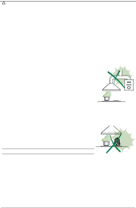
This rangehood requires at least 24" of clearance between the bottom of the rangehood and the cooking surface or countertop. Consult the cooktop or range installation instructions given by the manufacturer before making any cutouts. MOBILE HOME INSTALLATION. The installation of this rangehood must conform to the Manufactured Home Construction and Safety Standards, Title 24 CFR, Part 3280 (formerly Federal Standard for Mobile Home Construction and Safety, Title 24, HUD, Part 280). Four wire power supply must be used and the appliance wiring must be revised. See Electrical Requirements.
VENTING REQUIREMENTS
CAUTION - To reduce risk of fire and to properly exhaust air, be sure to duct air outside – Do not vent exhaust air into spaces within walls or ceilings or into attics, crawl spaces, or garages".
Determine which venting method is best for your application. Ductwork can extend either through the wall or the roof. The length of the ductwork and the number of elbows should be kept to a minimum to provide efficient performance. The size of the ductwork should be uniform. Do not install two elbows together. Use duct tape to seal all joints in the ductwork system. Use caulking to seal exterior wall or floor opening around the cap.
Flexible ductwork is not recommended. Flexible ductwork creates back pressure and air turbulence that greatly reduces performance.
Make sure there is proper clearance within the wall or floor for exhaust duct before making cutouts. Do not cut a joist or stud unless absolutely necessary. If a joist or stud must be cut, then a supporting frame must be constructed.
WARNING - To Reduce The Risk Of Fire, Use Only Metal Ductwork.
EN |
|
3 |
|
3 |

W A R N I N G
•Venting system MUST terminate outside the home.
•DO NOT terminate the ductwork in an attic or other enclosed space.
•DO NOT use 4" laundry-type wall caps.
•Flexible-type ductwork is NOT recommended.
•DO NOT obstruct the flow of combustion and ventilation air.
•Failure to follow venting requirements may result in a fire.
ELECTRICAL REQUIREMENTS
A 120 volt, 60 Hz AC-only electrical supply is required on a separate 15 amp fused circuit. A timedelay fuse or circuit breaker is recommended. The fuse must be sized per local codes in accordance with the electrical rating of this unit as specified on the serial/rating plate located inside the unit near the field wiring compartment. THIS UNIT MUST BE CONNECTED WITH COPPER WIRE ONLY. Wire sizes must conform to the requirements of the National Electrical Code, ANSI/NFPA 70 - latest edition, and all local codes and ordinances. Wire size and connections must conform with the rating of the appliance. Copies of the standard listed above may be obtained from:
National Fire Protection Association
Batterymarch Park
Quincy, Massachusetts 02269
This appliance should be connected directly to the fused disconnect (or circuit breaker) through flexible, armored or nonmetallic sheathed copper cable. Allow some slack in the cable so the appliance can be moved if servicing is ever necessary. A UL Listed, 1/2" conduit connector must be provided at each end of the power supply cable (at the appliance and at the junction box).
When making the electrical connection, cut a 1 1/4" hole in the wall. A hole cut through wood must be sanded until smooth. A hole through metal must have a grommet.
WARNING - TO REDUCE THE RISK OF FIRE OR ELECTRIC SHOCK, do not use this fan with any solid-state speed control device.
WARNING - TO REDUCE THE RISK OF FIRE, ELECTRICAL SHOCK, OR INJURY TO PERSONS, OBSERVE THE FOLLOWING: Use this unit only in the manner intended by the manufacturer. If you have any questions, contact the manufacturer.
Before servicing or cleaning unit, switch power off at service panel and lock the service disconnecting means to prevent power from being switched on accidentally. When the service disconnecting means cannot be locked, securely fasten a prominent warning device, such as a tag, to the service panel.
CAUTION: For General Ventilating Use Only. Do Not Use To Exhaust Hazardous or Explosive Materials and Vapors.
EN |
|
4 |
|
4 |
WARNING - TO REDUCE THE RISK OF FIRE, ELECTRICAL SHOCK, OR INJURY TO PERSONS, OBSERVE THE FOLLOWING: Installation Work And Electrical Wiring Must Be Done By Qualified Person(s) In Accordance With All Applicable Codes And Standards, Including Fire-Rated Construction.
Sufficient air is needed for proper combustion and exhausting of gases through the flue (chimney) of fuel burning equipment to prevent backdrafting. Follow the heating equipment manufacturer’s guideline and safety standards such as those published by the National Fire Protection Association (NFPA), and the American Society for Heating, Refrigeration and Air Conditioning Engineers (ASHRAE), and the local code authorities.
When cutting or drilling into wall or ceiling, do not damage electrical wiring and other hidden utilities.
Ducted fans must always be vented to the outdoors.
W A R N I N G
•Electrical ground is required on this rangehood.
•If cold water pipe is interrupted by plastic, nonmetallic gaskets or other materials, DO NOT use for grounding.
•DO NOT ground to a gas pipe.
•DO NOT have a fuse in the neutral or grounding circuit. A fuse in the neutral or grounding circuit could result in electrical shock
•Check with a qualified electrician if you are in doubt as to whether the rangehood is properly grounded.
•Failure to follow electrical requirements may result in a fire.
EN |
|
5 |
|
5 |
RECOMMENDATIONS AND SUGGESTIONS
 The Instructions for Use apply to several versions of this appliance. Accordingly, you may find descriptions of individual features that do not apply to your specific appliance.
INSTALLATION
•The manufacturer will not be held liable for any damages resulting from incorrect or improper installation.
•Check that the main voltage corresponds to that indicated on the rating plate fixed to the inside of the hood.
•The electrical supply must be properly and sufficiently grounded.
Connect the extractor to the exhaust flue through a pipe of minimum diameter 6”. The route of the flue must be as short as possible.
•Do not connect the extractor hood to exhaust ducts carrying combustion fumes (boilers, fireplaces, etc.).
•If the extractor is used in conjunction with non-electrical appliances (e.g. gas burning appliances), a sufficient degree of aeration must be guaranteed in the room in order to prevent the backflow of exhaust gas. The kitchen must have an opening communicating directly with the open air in order to guarantee the entry of clean air.
USE
•The range hood has been designed exclusively for domestic use to eliminate kitchen odors.
• Never use the hood for purposes other than for which it has ben designed.
• Never leave high naked flames under the hood when it is in operation.
• Adjust the flame intensity to direct it onto the bottom of the pan only, making sure that it does not engulf the sides.
• Deep fat fryers must be continuously monitored during use: overheated oil can burst into flames.
• The hood should not be used by children or persons not instructed in its correct use.
CARE
•Switch off or unplug the appliance from the main supply before carrying out any maintenance work.
•Clean and/or replace the Filters after the specified time period.
•Clean the hood using a damp cloth and a neutral liquid detergent..
THERMAL PROTECTOR
The range hood is equipped with a thermal protector to avoid overheating conditions. If the range hood shuts off in use, press the on/off button to return off range hood. Wait approximately 90 minutes, then press the on/off button to restart the range hood.
EN |
|
6 |
|
6 |

DIMENSIONS and MAIN PARTS
Dimensions
|
40" 9/16 |
22" 1/16 |
- |
26" 6/16 |
|
9" 7/16 |
23/32" |
29" 29/32 - 35" 11/32  5" 29/32
3" 15/16
Components
Ref. Q.ty Product Components
11 Hood Body, complete with: Controls, Light, Blower, Filters
2 |
1 |
Telescopic Chimney comprising: |
2.1 |
1 |
Upper Section |
2.2 |
1 |
Lower Section |
10 |
1 |
Damper |
15 |
1 |
Air Outlet Connection |
Ref. |
Q.ty |
Installation Components |
7.1 |
2 |
Hood Body Fixing Brackets |
7.2.1 |
1 |
Upper Chimney Section Fixing Brackets |
7.3 |
1 |
Air Outlet Connection Support |
11 |
8 |
Wall Plugs (if supplied) |
12a |
8 |
Screws 3/16” x 1” 3/4 |
12c |
6 |
Screws 1/8” x 3/8” |
12d |
2 |
Screws 3/16” x 1” |
12e |
2 |
Screws 1/8” x 1/2“ |
|
Q.ty |
Documentation |
|
1 |
Instruction Manual |
EN
9" 1/32 |
14" 5/32 |
27/32 - 19" 21/32 |
|
|
|
|
18" |
|
|
|
|
7.3 |
11 |
|
15 |
|
12a |
|
|
|
|
|
|
|
|
|
|
12e |
|
|
|
|
|
7.2.1 |
|
|
|
12c |
|
|
2.1 |
|
|
|
2 |
|
|
12c |
|
|
|
|
||
|
2.2 |
|
|
|
10 |
|
|
|
|
|
|
|
12c |
|
|
|
|
12a |
11 |
|
1 |
|
|
7.1 |
|
|
|
|
12d |
|
|
|
|
7 |
|
|
|
|
7 |
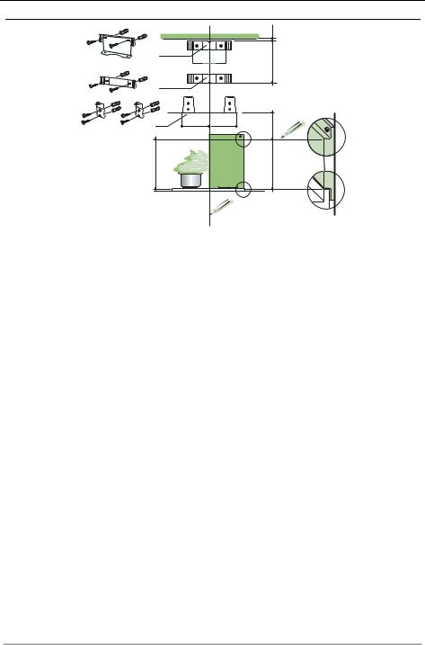
INSTALLATION
Wall drilling and bracket fixing
÷1/16"
7.3
X
7.2.1
7.1 |
4" 5/16 |
4" 5/16 |
|
7"1/2 |
|
|
|
|
24" |
|
H |
Wall marking:
•Draw a vertical line on the supporting wall up to the ceiling, or as high as practical, at the center of the area in which the hood will be installed.
•Draw a horizontal line at 24” above the hob for installation without the back panel, or at height H (height of the visible part of the panel) for installation with the back panel.
•Place bracket 7.3 on the wall as shown about 1/16” from the ceiling or upper limit, aligning the center (notch) with the vertical reference line.
•Mark the wall at the centers of the holes in the bracket.
•Place bracket 7.2.1 on the wall as shown at X” below the first bracket (X = height of the upper chimney section supplied), aligning the center (notch) with the vertical line.
•Mark the wall at the centers of the holes in the bracket.
•Place bracket 7.1 as shown 4” 5/16 from the vertical reference line and 7” 1/2 above the horizontal reference line.
•Mark the centres of the holes in the bracket.
•Repeat this operation on the other side.
REAR PANEL (OPTIONAL)
The Rear Panel must be fitted before fixing the hood body and, if it is to be fixed at both top and bottom, must be fitted at the correct height prior to installing the bases. As this operation is rather complex, it should be carried out either by the kitchen installer or a qualified person who knows the final dimensions of the units.
For fixing at the top only, proceed as follows:
•Rest the back panel on the base, inserting the lower plate between the upper surface and the wall, centring it on the vertical reference line.
•Mark the centres of the two holes in the upper plate.
•Drill ø 5/16” holes at all the centre points marked.
•Insert the wall plugs 11 in the holes.
•Fix the brackets using the 12a screws supplied.
•Fix the back panel (where present) using the 12a screws supplied.
EN |
|
8 |
|
8 |
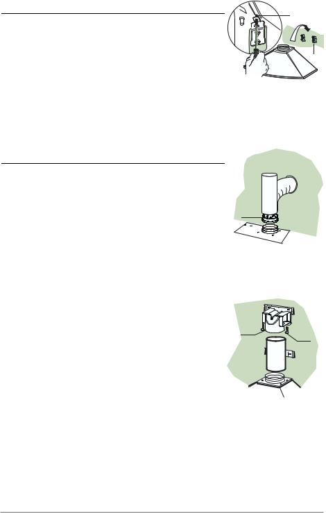
Mounting the hood body |
12.d |
|
• Screw the two screws 12d supplied onto the brackets 7.1. |
|
|
• Hook the hood body onto the bracket 7.1, centring it around |
|
|
the vertical line. |
|
|
• Use the adjusting screws 12d underneath the hood to level the |
7.1 |
|
hood body. |
||
|
Note: The Hood body should be secured to wall studs. If necessary, install a wood support behind the dry wall, flush mounted between 2 studs. This will provide the necessary structure and support for mounting.
Connections
DUCTED VERSION AIR EXHAUST SYSTEM
When installing the ducted version, connect the hood to the chimney using a rigid 6” duct.
•Install the damper 10 ø 6”.
•Fix the duct in position using sufficient pipe clamps (not supplied).
DUCTLESS VERSION AIR OUTLET
•Put connection 15 into the connection support 7.3.
•Fix to the support using the 2 screws 12e supplied
•Connect the air outlet connection 15 to the hood body outlet using either a rigid ø 6” pipe(not supplied).
•Ensure that the activated charcoal filters have been inserted.
10
15
12e
EN |
|
9 |
|
9 |
 Loading...