

Page 1

Istruzioni per l’uso e l’installazione
Instructions for use and installation
Mode d’emploi et installation
Bedienungsanleitung und Einrichtung
Kullan
ım ve montaj talimatları
IT
Cappa
GB
Cooker Hood
FR
Hotte de Cuisine
DE
Dunstabzugshaube
TR
Davlumbaz
FTU 3807 I
Page 2

IT
Libretto di Istruzioni
INDICE
CONSIGLI E SUGGERIMENTI.............................................................................................................................................. 7
CARATTERISTICHE..............................................................................................................................................................8
INSTALLAZIONE .................................................................................................................................................................10
USO......................................................................................................................................................................................14
MANUTENZIONE.................................................................................................................................................................15
2
2
Page 3

EN
Instructions Manual
INDEX
RECOMMENDATIONS AND SUGGESTIONS ................................................................................................................... 17
CHARACTERISTICS...........................................................................................................................................................18
INSTALLATION....................................................................................................................................................................20
USE......................................................................................................................................................................................24
MAINTENANCE...................................................................................................................................................................25
3
3
Page 4

FR
Manuel d’Instructions
SOMMAIRE
CONSEILS ET SUGGESTIONS..........................................................................................................................................27
CARACTERISTIQUES.........................................................................................................................................................28
INSTALLATION....................................................................................................................................................................30
UTILISATION.......................................................................................................................................................................34
ENTRETIEN.........................................................................................................................................................................35
4
4
Page 5

DE
Bedienungsanleitung
INHALTSVERZEICHNIS
EMPFEHLUNGEN UND HINWEISE................................................................................................................................... 37
CHARAKTERISTIKEN.........................................................................................................................................................38
MONTAGE...........................................................................................................................................................................40
BEDIENUNG........................................................................................................................................................................44
WARTUNG...........................................................................................................................................................................45
5
5
Page 6

TR
Kullanim Kilavuku
IÇERIKLER
TAVSIYELER VE ÖNERILER.............................................................................................................................................. 47
ÖZELLIKLER........................................................................................................................................................................48
MONTAJ...............................................................................................................................................................................50
KULLANIM ...........................................................................................................................................................................54
BAKIM ..................................................................................................................................................................................55
6
6
Page 7

IT
650 mm min.
CONSIGLI E SUGGERIMENTI
INSTALLAZIONE
• Il produttore declina qualsiasi responsabilità per danni dovuti
ad installazione non corretta o non conforme alle regole
dell’arte.
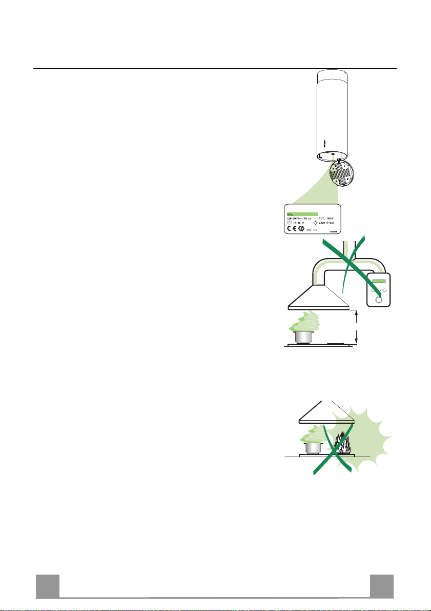
• La distanza minima di sicurezza tra il Piano di cottura e la
Cappa deve essere di 650 mm.
• Verificare che la tensione di rete corrisponda a quella riportata
nella targhetta posta all’interno della Cappa.
• Per Apparecchi in Classe Ia accertarsi che l’impianto elettrico
domestico garantisca un corretto scarico a terra.
• Collegare la Cappa all’uscita dell’aria aspirata con tubazione di
diametro pari o superiore a 120 mm. Il percorso della tubazione deve essere il più breve possibile.
• Non collegare la Cappa a condotti di scarico dei fumi prodotti
da combustione (caldaie, caminetti, ecc.).
• Nel caso in cui nella stanza vengano utilizzati sia la Cappa che
apparecchi non azionati da energia elettrica (ad esempio apparecchi utilizzatori di gas), si deve provvedere ad una aerazione
sufficiente dell’ambiente. Se la cucina ne fosse sprovvista, praticare un’apertura che comunichi con l’esterno, per garantire il
richiamo d’aria pulita.
USO
• La Cappa è stata progettata esclusivamente per uso domestico,
per abbattere gli odori della cucina.
• Non fare mai uso improprio della Cappa.
• Non lasciare fiamme libere a forte intensità sotto la Cappa in
funzione.
• Regolare sempre le fiamme in modo da evitare una evidente
fuoriuscita laterale delle stesse rispetto al fondo delle pentole.
• Controllare le friggitrici durante l’uso: l’olio surriscaldato potrebbe infiammarsi.
• La Cappa non deve essere utilizzata da bambini o persone non
abilitate all’uso corretto.
MANUTENZIONE
• Prima di procedere a qualsiasi operazione di manutenzione,
disinserire la Cappa togliendo la spina elettrica o spegnendo
l’interruttore generale.
• Effettuare una scrupolosa e tempestiva manutenzione dei Filtri
secondo gli intervalli consigliati.
• Per la pulizia delle superfici della Cappa è sufficiente utilizzare
un panno umido e detersivo liquido neutro.
7
7
Page 8
IT
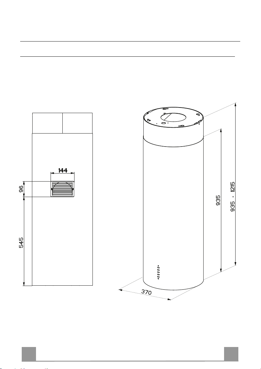
CARATTERISTICHE
Ingombro
8
8
Page 9
IT
2
11
12h
22
23
21
7.1
1
12g
14
9
25
8
7.1a
7.1b
15
14.1
14.2
12f
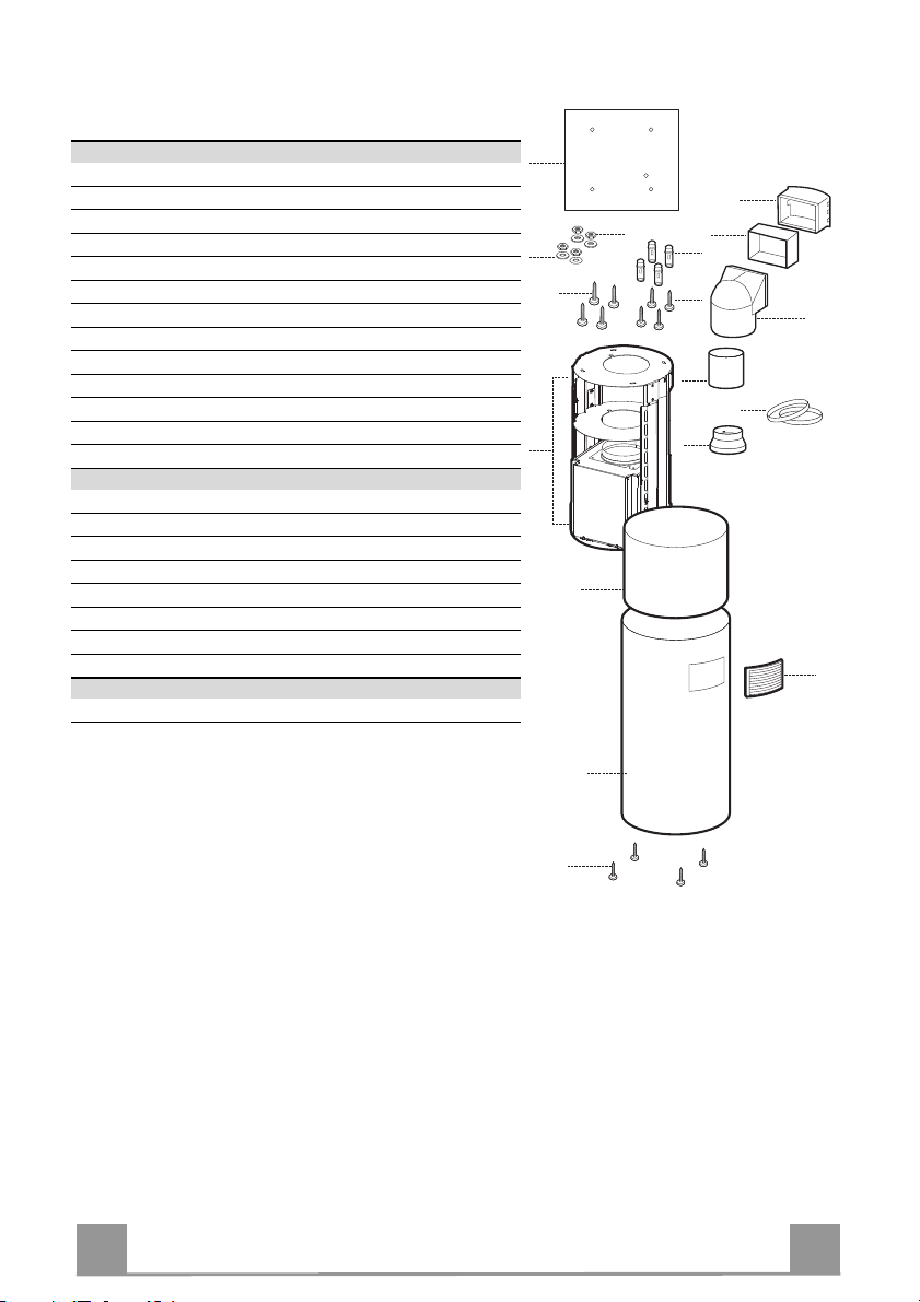
Componenti
Rif. Q.tà Componenti di Prodotto
1 1 Corpo Cappa completo di: Comandi, Luce, Filtri
2 1 Camino superiore
7.1 1 Traliccio telescopico completo di Aspiratore,formato da:
7.1a 1 Traliccio superiore
7.1b 1 Traliccio inferiore
8 1 Griglia Direzionata Uscita Aria
9 1 Flangia di riduzione ø 150-120 mm
14 1 Prolunga Uscita Aria Corpo Cappa
14.1 1 Prolunga Raccordo Uscita Aria
14.2 1 Prolunga Uscita Aria
15 1 Raccordo Uscita Aria
25 2 Fascette stringitubo
Rif. Q.tà Componenti di Installazione
11 4 Tasselli ø 10
12f 4 Viti M6 x 15
12g 4 Viti M6 x 80
12h 4 Viti 5,2 x 70
21 1 Dima di foratura
22 4 Rondelle øi 6,4
23 4 Dadi M6
Q.tà Documentazione
1 Libretto Istruzioni
9
9
Page 10
IT
1
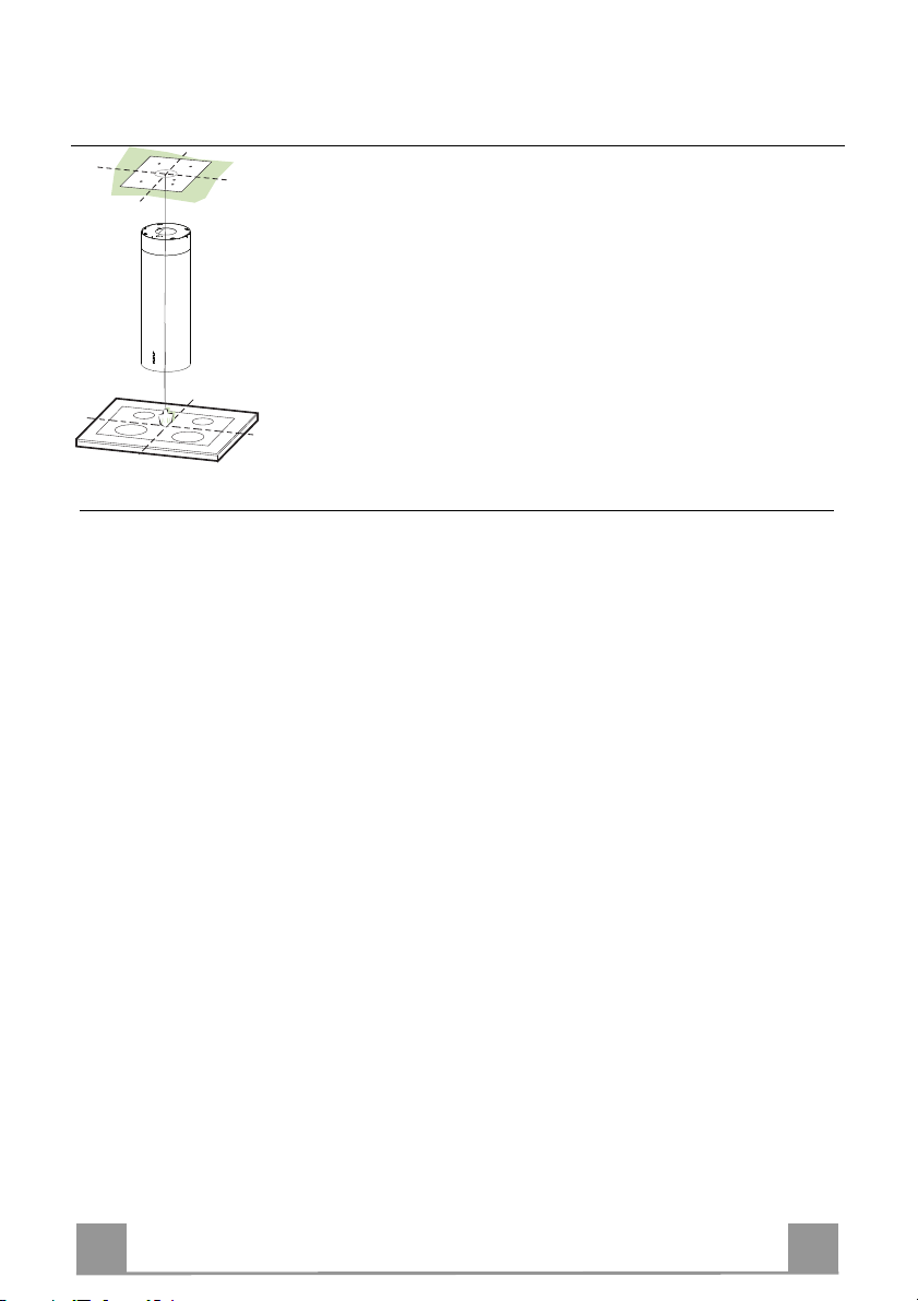
INSTALLAZIONE
Foratura Soffitto/Mensola e Fissaggio Traliccio
FORATURA SOFFITTO/MENSOLA
• Con l’ausilio di un Filo a piombo riportare sul Soffitto/Mensola di supporto il centro del
Piano di Cottura.
• Appoggiare al Soffitto/Mensola la Dima di Foratura 21 in dotazione, facendo coincidere il
suo centro al centro proiettato e allineando gli assi della Dima agli assi del Piano di Cottura.
• Segnare i centri dei Fori della Dima.
• Forare i punti seguenti:
• Soffitto in Calcestruzzo massiccio: secondo Tasselli per Calcestruzzo impiegati.
• Soffitto in Laterizio a camera d’aria, con spessore resistente di 20 mm: ø 10 mm (inserire
subito i Tasselli 11 in dotazione).
• Soffitto in Travatura di Legno: secondo Viti per Legno impiegate.
• Mensola in Legno: ø 7 mm.
• Passaggio del Cavo elettrico di Alimentazione: ø 10 mm.
• Uscita Aria (Versione Aspirante): secondo diametro del collegamento alla Tubazione di
Evacuazione Esterna.
• Avvitare, incrociandole e lasciando 4-5 mm dal soffitto, due viti:
• per Calcestruzzo massiccio, Tasselli per Calcestruzzo, non in dotazione.
• per Laterizio a camera d’aria, con spessore resistente di 20 mm circa, Viti 12h, in dotazio-
ne.
• per Travatura di legno, Viti per legno, non in dotazione.
• per Mensola in Legno, viti 12g con Rondelle 22 e Dadi 23, in dotazione.
10
Page 11
IT
1
A
B
2
1
1
2
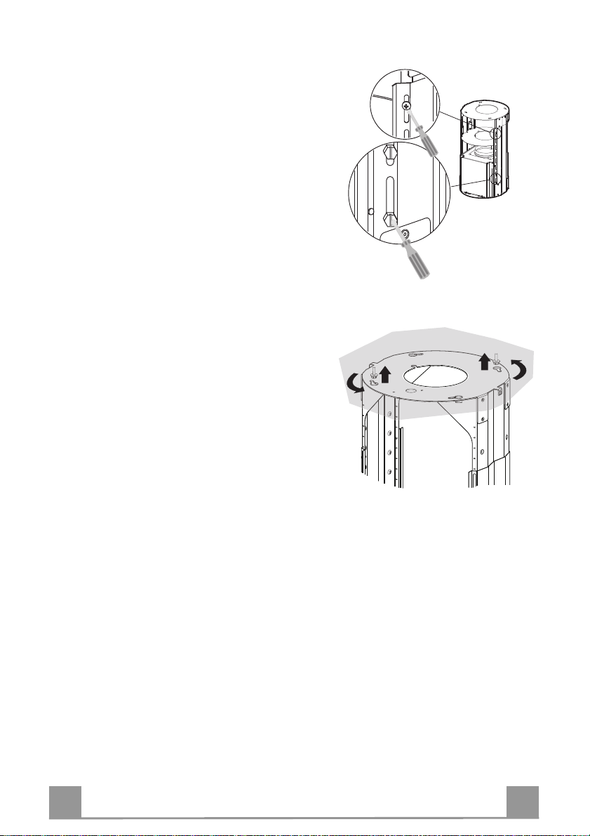
FISSAGGIO TRALICCIO
• Svitare le due viti che fissano il camino superiore 2.1
al traliccio e sfilare il camino dalla parte superiore.
Nel caso in cui si voglia regolare l’altezza del traliccio
procedere come segue:
• Svitare le quattro viti di sicurezza poste in alto nella
zona di separazione del traliccio. (A)
• Svitare le otto viti metriche che uniscono le due colonne, poste ai lati del traliccio. (B)
• Regolare l’altezza desiderata del traliccio e riavvitare
le viti precedentemente tolte.
• Per garantire una maggiore stabilità al traliccio riavvitare le quattro viti di
sponibile.
• Inserire il camino superiore dall’alto e lasciarlo libero
sul traliccio.
• Sollevare il traliccio facendo attenzione che l’indice
posto sopra la piastra del traliccio sia nella parte posteriore.
• Incastrare le asole del traliccio sulle due viti predisposte precedentemente al soffitto e ruotare fino al
centro dell’asola di regolazione.
• Stringere le due viti e avvitare le altre due in dotazione; prima di serrare definitivamente le viti è possibile
effettuare delle regolazioni ruotando il traliccio, facendo attenzione che le viti non escano dalla sede
dell’asola di regolazione.
• Il fissaggio del Traliccio deve essere sicuro in relazione sia al peso della Cappa sia alle sollecitazioni
causate da occasionali spinte laterali all’Apparecchio
montato. A fissaggio avvenuto verificare quindi che
la base sia stabile anche se il Traliccio è sollecitato a
flessione.
• In tutti i casi in cui il Soffitto non fosse sufficientemente robusto sul punto di sospensione, l’Installatore
dovrà provvedere a irrobustirlo con opportune piastre
e contropiastre ancorate a parti strutturalmente resistenti.
sicurezza sull’ultimo foro di-
11
Page 12
IT
1
9
ø 120ø 150
15
14
9
14.2
Connessione Uscita aria Versione Aspirante
Per installazione in Versione Aspirante collegare la
Cappa alla tubazione di uscita per mezzo di un tubo
rigido o flessibile di ø 150 o 120 mm, la cui scelta è
lasciata all’installatore.
• Per collegamento con tubo ø 120 mm, inserire la
Flangia di riduzione 9 sull’Uscita del Corpo Cappa.
• Fissare il tubo con adeguate fascette stringitubo 25 in
dotazione.
• Rimuovere eventuali filtri al carbone attivo.
Connessione Uscita aria Versione Filtrante
• Inserire la Flangia di riduzione 9 sull’uscita
dell’Aspiratore.
• Inserire a pressione la Prolunga 14 sulla Flangia.
• Inserire a pressione il Raccordo 15 sulla Prolunga.
• Inserire lateralmente la Prolunga 14.2 sul Raccordo
15, assicurandosi che l’uscita risulti in corrispondenza della Bocchetta del Camino.
12
Page 13
IT
1
8
14.1
2
1
Cmd
Lux
Montaggio Camino e Fissaggio Corpo Cappa
• Posizionare il Camino superiore e fissare nella parte superiore
al Traliccio con 2 Viti tolte in precedenza.
• Aprire il gruppo illuminazione tirandolo sull’apposita intacca,
sganciarlo dal corpo cappa facendo scorrere l’apposito perno di
fissaggio;
• Togliere il Filtro Antigrasso, spingendolo verso la parte posteriore del gruppo e tirando contemporaneamente verso il basso.
• Togliere eventuali Filtri Antiodore al Carbone attivo.
• Predisporre il fissaggio del corpo cappa al traliccio avvitando
le 4 Viti 12f nelle apposite sedi.Lasciare almeno 4-5 mm di
spazio tra la testa della vite e la piastra del traliccio.
• Agganciare il corpo cappa al traliccio e ruotare verso sinistra
fino alla battuta, procedere immediatamente al serraggio delle
viti così da evitare un’accidentale caduta del corpo cappa.
Versione filtrante
• Assicurarsi che l’uscita della Prolunga raccordo 14.2 sia in corrispondenza della Bocchetta del Camino.
• Se così non fosse, rimuovere il corpo cappa e aggiustare la posizione della Prolunga 14; rimontare quindi i particolari come
prima descritto.
• Inserire lateralmente la Prolunga Raccordo 14.1 sulla Prolunga
14.2,
• Applicare la Griglia direzionata 8 nell’apposita sede. Assicurarsi inoltre che risulti inserita correttamente nel Raccordo 14.1
CONNESSIONE ELETTRICA
• Collegare la Cappa all’Alimentazione di Rete interponendo un
Interruttore bipolare con apertura dei contatti di almeno 3 mm.
• Assicurarsi che il connettore del Cavo alimentazione sia correttamente inserito nella presa dell’Aspiratore.
• Collegare il connettore dei Comandi Cmd.
• Collegare il connettore dei Faretti Lux alla presa predisposta
dietro al coperchio del gruppo illuminazione.
• Per la Versione Filtrante montare il Filtro Antiodore al Carbone attivo.
• Rimontare il Filtro Antigrasso e successivamente il gruppo illuminazione.
13
Page 14
IT
1
L
S1
T1
T2
T3
T4
USO
Quadro comandi
La cappa può essere accesa direttamente alla velocità desiderata, premendo
il relativo tasto senza passare per il tasto 0/1 motore.
TASTO LED FUNZIONI
L - Accende e spegne l’impianto di
illuminazione.
T1 0/1 Motore Fisso Prima velocità.
Spegne la cappa se premuto per
circa 1”.
T2 Velocità Fisso Seconda velocità.
T3 Velocità Fisso Terza velocità.
T4 Velocità Fisso Velocità massima.
Lampeggiante Velocità intensiva.
Adatta a fronteggiare le massime
emissioni di fumi di cottura. Si atti-
va premendo per circa 2” il tasto. Si
spegne automaticamente dopo 10
minuti dall’entrata in funzione. Può
essere disinserita manualmente
premendo qualsiasi tasto velocità.
S1 Led Fisso Segnala l’allarme saturazione Filtri
Antigrasso Metallici e la necessità
di lavarli. L’allarme entra in fun-
zione dopo 100 ore di lavoro effet-
tivo della Cappa. (Reset vedi pa-
rag. Manutenzione)
Lampeggiante Segnala, quando è attivato,
l’allarme saturazione Filtro Antio-
dore al Carbone Attivo, che deve
essere sostituito; devono anche es-
sere lavati i Filtri Antigrasso Me-
tallici. L’allarme saturazione Filtro
Antiodore al Carbone Attivo entra
in funzione dopo 200 ore di lavoro
effettivo della Cappa. (Attivazione
e Reset vedi parag. Manutenzione)
14
Page 15
IT
1
MANUTENZIONE
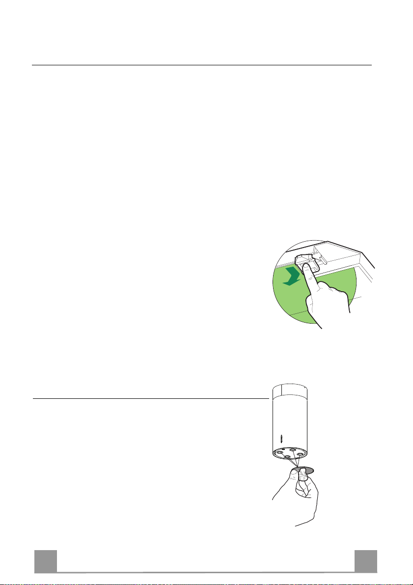
TELECOMANDO (OPZIONALE)
Questo apparecchio può essere comandato per mezzo di un telecomando, alimentato con pile alcaline zinco-carbone da 1,5 V del
tipo standard LR03-AAA.
• Non riporre il telecomando in prossimità di fonti di calore.
• Non disperdere le pile nell’ambiente, depositarle negli appositi
contenitori.
Filtri antigrasso metallici
PULIZIA FILTRI ANTIGRASSO METALLICI
Reset del segnale di allarme
• Spegnere le Luci e il Motore di aspirazione.
• Premere il tasto T3 per almeno 3 secondi, sino al lampeggio di
conferma dei led.
Pulizia Filtri
• Sono lavabili in lavastoviglie e necessitano di essere lavati
quando si accende il led S1 o al massimo ogni 2 mesi di utilizzo.
• Aprire il gruppo illuminazione tirandolo sull’apposita intacca.
• Togliere i Filtri uno alla volta, spingendoli verso la parte poste-
riore del gruppo e tirando contemporaneamente verso il basso.
• Lavare i Filtri evitando di piegarli, e lasciarli asciugare prima
di rimontarli.
• Rimontarli facendo attenzione a mantenere la maniglia verso la
parte visibile esterna.
• Richiudere il gruppo illuminazione.
15
Page 16
IT
1
Filtri antiodore al Carbone attivo (Versione Filtrante)
• Non è lavabile e non è rigenerabile, va sostituito quando il led S1 lampeggia o almeno ogni
4 mesi. La segnalazione di allarme si verifica solo quando é azionato il Motore di aspirazione.
Attivazione del segnale di allarme
• Nelle Cappe in Versione Filtrante, la segnalazione di Allarme saturazione Filtri va attivata al
momento dell’installazione o successivamente.
• Spegnere le Luci e il Motore di aspirazione.
• Scollegare la cappa dall’alimentazione di rete.
• Ripristinare il collegamento tenendo premuto il tasto T1.
• Rilasciare il tasto, tutti e cinque i led sono accesi in posizione fissa
• Entro 3 secondi premere il Tasto T1 sino al lampeggio di conferma dei Led T1 e T4:
• 2 lampeggi Led - Allarme saturazione Filtro antiodore al Carbone attivo ATTIVATO
• 1 lampeggio Led - Allarme saturazione Filtro antiodore al Carbone attivo DISATTIVATO
SOSTITUZIONE
Reset del segnale di allarme
• Spegnere le Luci e il Motore di aspirazione
• Premere il tasto T3 per almeno 4 secondi, sino al lampeggio di
conferma dei led.
Sostituzione Filtro
• Aprire il gruppo illuminazione tirando l’apposita intacca.
• Rimuovere il Filtro antigrasso
• Rimuovere il Filtro antiodore al Carbone attivo saturo, agendo
sugli appositi agganci.
• Montare il nuovo Filtro agganciandolo nella sua sede.
• Rimontare il Filtro antigrasso e il gruppo illuminazione.
Illuminazione
SOSTITUZIONE LAMPADE
Lampade alogene da 20 W
• Estrarre la Lampada dal Supporto.
• Sostituirla con una nuova di uguali caratteristiche, facendo attenzione ad inserire correttamente i due spinotti nella sede del
Supporto.
16
Page 17
EN
1
650 mm min.
RECOMMENDATIONS AND SUGGESTIONS
INSTALLATION
• The manufacturer will not be held liable for any damages resulting
from incorrect or improper installation.
• The minimum safety distance between the cooker top and the extractor hood is 650 mm.
• Check that the mains voltage corresponds to that indicated on the
rating plate fixed to the inside of the hood.
• For Class I appliances, check that the domestic power supply guarantees adequate earthing.
Connect the extractor to the exhaust flue through a pipe of minimum
diameter 120 mm. The route of the flue must be as short as possible.
• Do not connect the extractor hood to exhaust ducts carrying combustion fumes (boilers, fireplaces, etc.).
• If the extractor is used in conjunction with non-electrical appliances
(e.g. gas burning appliances), a sufficient degree of aeration must be
guaranteed in the room in order to prevent the backflow of exhaust
gas. The kitchen must have an opening communicating directly with
the open air in order to guarantee the entry of clean air.
USE
• The extractor hood has been designed exclusively for domestic use to
eliminate kitchen smells.
• Never use the hood for purposes other than for which it has ben designed.
• Never leave high naked flames under the hood when it is in operation.
• Adjust the flame intensity to direct it onto the bottom of the pan only,
making sure that it does not engulf the sides.
• Deep fat fryers must be continuously monitored during use: overheated oil can burst into flames.
• The hood should not be used by children or persons not instructed in
its correct use.
MAINTENANCE
• Switch off or unplug the appliance from the mains supply before carrying out any maintenance work.
• Clean and/or replace the Filters after the specified time period.
• Clean the hood using a damp cloth and a neutral liquid detergent.
17
Page 18

EN
1
CHARACTERISTICS
Dimensions
18
Page 19

EN
1
2
11
12h
22
23
21
7.1
1
12g
14
9
25
8
7.1a
7.1b
15
14.1
14.2
12f
Components
Ref. Q.ty Product Components
1 1 Hood Body, complete with: Controls, Light, Blower,
2 1 Chimney Upper
7.1 1 Telescopic frame complete with extractor, consisting of:
7.1a 1 Upper frame
7.1b 1 Lower frame
8 1 Air Outlet Grill
9 1 Reducer Flange ø 150-120 mm
14 1 Hood Body Air Outlet Extension Piece
14.1 1 Air Outlet Connection Extension
14.2 1 Air Outlet Extension
15 1 Air Outlet Connection
25 2 Pipe clamps
Ref. Q.ty Installation Components
11 4 Wall Plugs ø 10
12f 4 Screws M6 x 10
12g 4 Screws M6 x 80
12h 4 Screws 5,2 x 70
21 1 Drilling template
22 4 6.4 mm int. dia washers
23 4 M6 nuts
Q.ty Documentation
1 Instruction Manual
Filters
19
Page 20

EN
2
INSTALLATION
Drilling the Ceiling/shelf and fixing the frame
DRILLING THE CEILING/SHELF
• Use a plumb line to mark the centre of the hob on the ceiling/support shelf.
• Place the drilling template 21 provided on the ceiling/support shelf, making sure that the
template is in the correct position by lining up the axes of the template with those of the hob.
• Mark the centres of the holes in the template.
• Drill the holes at the points marked:
• For concrete ceilings, drill for plugs appropriate to the screw size.
• For hollow brick ceilings with wall thickness of 20 mm: drill ø 10 mm(immediately insert
the Dowels 11 supplied).
• For wooden beam ceilings, drill according to the wood screws used.
• For wooden shelf, drill ø 7 mm.
• For the power supply cable feed, drill ø 10 mm.
• For the air outlet (Ducted Version), drill according to the diameter of the external air ex-
haust duct connection.
• Insert two screws of the following type, crossing them and leaving 4-5 mm from the ceiling:
• For concrete ceilings, use the appropriate plugs for the screw size (not provided).
• for Cavity ceiling with inner space, with wall thickness of approx. 20 mm, Screws 12h,
supplied.
• For wooden beam ceilings, use 4 wood screws (not provided).
• For wooden shelf, use 4 screws 12g with washers 22 and nuts 23, provided.
20
Page 21

EN
2
sure against the fitted Appliance.
A
B
2
1
1
2
FIXING THE FRAME
• Unfasten the two screws fastening the upper chimney
stack 2.1 to the frame, and remove the chimney from
the upper stack.
If you wish to adjust the height of the frame, proceed as
follows:
• Unfasten the four safety screws located at the top in
the frame separation area. (A)
• Unfasten the eight metric screws joining the two columns, located at the sides of the frame. (B)
• Adjust the frame to the height required, then replace
all the screws removed as above.
• To guarantee greater stability in the frame, replace
the four safety screws in the last hole available.
• Insert the upper chimney stack from above, and leave
it running free on the frame.
• Lift the frame up, making sure that the index over the
frame plate is turned backwards.
• Fit the frame slots onto the two screws inserted in the
ceiling as above, and turn until reaching the centre of
the adjustment slot.
• Tighten the two screws and fasten the other two
screws provided; before locking the screws completely, it is possible to adjust the frame by turning it,
making sure that the screws do not come out of their
housing in the adjustment slot.
• The Frame must be securely fastened so as to support
both the weight of the Hood and the stress caused by
occasional axial pres
After fixing, make sure that the base is stable even
when the Frame is subjected to lateral stress.
• If the Ceiling is not strong enough in the area where
the hood is to be fixed, the Installer must strengthen
the area using suitable plates and counterplates anchored to resistant structures.
21
Page 22

EN
2
9
ø 120ø 150
15
14
9
14.2
Ducted version air exhaust system Connection
When installing the ducted version, connect the hood to
the chimney using either a flexible or rigid pipe ø 150
or 120 mm, the choice of which is left to the installer.
• To install a ø 120 mm air exhaust connection, insert
the reducer flange 9 on the hood body outlet.
• Fix the pipe using the pipe clamps 25 provided.
• Remove any activated charcoal filters.
Recirculation version air outlet connection
• Insert reducer flange 9 on the extractor outlet.
• Push fit the extension piece 14 onto the flange.
• Push fit connector 15 onto the extension piece.
• Insert extension piece 14.2 laterally on connector 15,
ensuring that the outlet is in line with the chimney intake.
22
Page 23

EN
2
8
14.1
2
1
Cmd
Lux
Fitting the Upper Chimney and the Hood Body
• Position the upper chimney stack and . x the top of it to the
frame using 2 of the screws removed as above.
• Open the lighting unit by pulling on the notch, disconnect it
from the hood canopy by sliding out the pin.
• Remove the filters one at a time by pushing them towards the
back of the group and pulling down at the same time.
• Remove the activated charcoal filters, if fitted.
• In order to fix the hood body to the frame insert the 4 screws
12f in their seats. It is necessary to leave at least 4-5 mm gap
between the screw heads and the frame plate.
• Hook the hood canopy to the frame and turn it to the left until
it reaches the stop, then lock the screws immediately to prevent
the hood canopy from falling out accidentally.
Recirculation version
• Make sure that the outlet of the extension piece 14.2 is horizontally and vertically aligned with the chimney outlet.
• If this is not the case, remove the lower Chimney Stack and
adjust the position of Extension 14; replace the elements as described above.
• Insert Connector Extension 14.1 sideways into Extension 14.2.
• Fit the directional grill 8 into the housing provided. Also make
sure that it is properly fitted into connector 14.1.
ELECTRICAL CONNECTION
• Connect the Hood to the mains power supply, inserting a twopole cut-out switch with contact aperture of at least 3 mm
along the line.
• Ensure that the supply cable connector is properly inserted into
the Suction device socket
• Hook up the Commands connector Cmd.
• Hook up the Spotlights connector Lux to the socket provided
behind the lighting unit cover.
• For the Recirculation Version, fit the Activated Charcoal
Odour Filter.
• Replace the filters and the lighting unit.
23
Page 24

EN
2
L
S1
T1
T2
T3
T4
USE
Control Panel
The hood can be switched on pushing directly onto the requested speed
without firstly having to select 0/1 button.
KEY LED FUNCTIONS
L 0/1 Light Turns lighting on and off.
T1 0/1 Motor on First speed.
When pressed for about 1 seconds
the motor is switched off.
T2 Speed on Second speed.
T3 Speed on Third speed.
T4 Speed Fixed Max. speed
Flashing Intensive speed.
Suitable for the strongest cooking
vapours and odours. The function
becomes active when the button is
pushed for about 2 seconds. After
10 minutes of functioning it turns
off automatically. This function
can be interrupted by means of
pressing any of the buttons.
S1 Led Fixed Indicates that the Metal grease fil-
ters saturation alarm has been trig-
gered, and the filters need to be
washed. The alarm is triggered af-
ter 100 working hours. (Reset;
check the Maintenance-paragraph)
Flashing indicates that the activated char-
coal odour filter saturation alarm
has been triggered, and the filter
has to be replaced; the metal grease
filters must also be washed. The
activated charcoal odour filter is
triggered after 200 working hours.
(Activation and Reset; check the
Maintenance-paragraph)
24
Page 25

EN
2
MAINTENANCE
REMOTE CONTROL (OPTIONAL)
The appliance can be controlled using a remote control powered
by a 1.5 V carbon-zinc alkaline batteries of the standard LR03AAA type.
• Do not place the remote control near to heat sources.
• Used batteries must be disposed of in the proper manner.
Grease filters
CLEANING METAL SELF- SUPPORTING GREASE FILTERS
Alarm signal reset
• Switch off the lights and extractor motor.
• Press button T3 for at least 3 seconds, until the leds start to
flash.
Cleaning the filters
• The filters are washable and must be cleaned when the LED S1
lights up or at least every 2 months of operation, or more frequently for particularly heavy usage.
• Open the lighting unit by pulling on the nocth.
• Remove the filters one at a time by pushing them towards the
back of the group and pulling down at the same time.
• Wash the filters, taking care not to bend them. Allow them to
dry before refitting.
• When refitting the filters, make sure that the handle is visible
on the outside.
• Replace the lighting unit.
25
Page 26

EN
2
Activated charcoal filter (Recirculation version)
• The filter is not washable and cannot be regenerated. It must be replaced when led S1
flashes or at least every 4 months. The alarm signal will only light up when the extractor
motor is switched on.
Alarm signal activation
• In Recirculation version Hoods, the Filter saturation alarm can be enabled on installation or
at a later date. Turn the Lights and the suction Motor off.
• Disconnect the Hood using the Main switch or the double-pole switch on the mains power
supply.
• Restore the connection by pressing and holding T1.
• Release the button. All five LEDs are turned on
• Within 3 seconds press T1 until LEDs T1 and T4 flash in confirmation:
LED flashes twice - Activated charcoal filter saturation alarm ENABLED
LED flashes once - Activated charcoal filter saturation alarm DISABLED
REPLACING
Alarm signal reset
• Turn the Lights and the suction Motor off.
• Press T3 for at least 4 seconds, until indicators T1 and T4 flash
to confirm.
Replacing the Filter
• Open the lighting unit by pulling on the nocth
• Remove the metal grease filters
• Remove the saturated activated carbon filter by releasing the
fixing hooks
• Fit the new filter by hooking it into its seating
• Replace the metal grease filters and the lighting unit.
Lighting
LIGHT REPLACEMENT
20 W halogen light.
• Extract the lamp from the lamp holder by pulling gently.
• Replace with another of the same type, making sure that the
two pins are properly inserted in the lamp holder socket holes.
26
Page 27

FR
2
INSTALLATION
650 mm min.
CONSEILS ET SUGGESTIONS
• Le fabricant décline toute responsabilité en cas de dommage dû à
une installation non correcte ou non conforme aux règles de l’art.
• La distance minimale de sécurité entre le plan de cuisson et la hotte
doit être de 650 mm au moins.
• Vérifier que la tension du secteur correspond à la valeur qui figure sur
la plaquette apposée à l’intérieur de la hotte.
• Pour les Appareils appartenant à la Ière Classe, veiller à ce que la
mise à la terre de l’installation électrique domestique ait été effectuée
conformément aux normes en vigueur.
• Connecter la hotte à la sortie d’air aspiré à l’aide d’une tuyauterie
d’un diamètre égal ou supérieur à 120 mm. Le parcours de la
tuyauterie doit être le plus court possible.
• Eviter de connecter la hotte à des conduites d’évacuation de fumées
issues d’une combustion tel que (Chaudière, cheminée, etc…).
• Si vous utilisez des appareils qui ne fonctionnent pas à l’électricité
dans la pièce ou est installée la hotte (par exemple: des appareils
fonctionnant au gaz), vous devez prévoir une aération suffisante du
milieu. Si la cuisine en est dépourvue, pratiquez une ouverture qui
communique avec l’extérieur pour garantir l’infiltration de l’air pur.
UTILISATION
• La hotte a été conçue exclusivement pour l’usage domestique, dans
le but d’éliminer les odeurs de la cuisine.
• Ne jamais utiliser abusivement la hotte.
• Ne pas laisser les flammes libres à forte intensité quand la hotte est
en service.
• Toujours régler les flammes de manière à éviter toute sortie latérale
de ces dernières par rapport au fond des marmites.
• Contrôler les friteuses lors de l’utilisation car l’huile surchauffée
pourrait s’enflammer.
• La hotte ne doit pas être utilisée par des enfants ou des personnes ne
pouvant pas assurer une utilisation correcte.
ENTRETIEN
• Avant de procéder à toute opération d’entretien, retirer la hotte en
retirant la fiche ou en actionnant l’interrupteur général.
• Effectuer un entretien scrupuleux et en temps dû des Filtres, à la
cadence conseillée.
• Pour le nettoyage des surfaces de la hotte, il suffit d’utiliser un
27
Page 28

FR
2
CARACTERISTIQUES
Encombrement
28
Page 29

FR
2
2
11
12h
22
23
21
7.1
1
12g
14
9
25
8
7.1a
7.1b
15
14.1
14.2
12f
Composants
Réf. Q.té Composants de Produit
1 1 Corps Hotte équipé de: Comandes, Lumière, Filtres
2 1 Cheminée Télescopique formée de :
2.1 1 Cheminée Supérieure
2.2 1 Cheminée Inférieure
7.1 1 Treillis télescopique avec Aspirateur, formé par:
7.1a 1 Treillis supérieur
7.1b 1 Treillis inférieur
8 1 Grille Sortie Air
9 1 Flasque de Réduction ø 150-120 mm
14 1 Rallonge Sortie Air Corps Hotte
14.1 1 Rallonge Raccord Sortie Air
14.2 1 Rallonge Sortie Air
15 1 Raccord Sortie Air
25 2 Colliers de serrage serre-tube
Réf. Q.té Composants pour l’installation
11 4 Chevilles ø 10
12f 4 Vis M6 x 15
12g 4 Vis M6 x 80
12h 4 Vis 5,2 x 70
21 1 Gabarit de perçage
22 4 Rondelles øi 6,4
23 4 Écrous M6
Q.té Documentation
1 Manuel d’instructions
29
Page 30

FR
3
INSTALLATION
Perçage Plafond/Étagère et Fixation Treillis
PERÇAGE PLAFOND/ETAGERE
• À l’aide d’un Fil à plomb, reporter sur le Plafond/Étagère de support le centre du Plan de
Cuisson.
• Poser contre le Plafond/Étagère le Gabarit de Perçage 21 fourni avec l’appareil, en faisant
coïncider son centre avec le centre projeté et en alignant les axes du Gabarit avec les axes du
Plan de Cuisson.
• Marquer les centres des Trous du Gabarit.
• Percer les trous qui ont été marqués:
• Plafond en Béton massif: en fonction des Goujons pour Béton utilisés.
• Plafond en Briques avec chambre à air, avec épaisseur résistante de 20 mm: ø 10 mm (in-
sérer immédiatement les Chevilles 11 fournies avec l’appareil).
• Plafond en Poutrage en Bois: en fonction des Vis à Bois utilisées.
• Étagère en Bois: ø 7 mm.
• Passage du Câble électrique d’Alimentation: ø 10 mm.
• Sortie Air (Version Aspirante): en fonction du diamètre de la connexion avec les Tuyaux
d’Évacuation Externe.
• Visser deux vis en les croisant et en laissant 4-5 mm. de distance par rapport au plafond:
• pour le Béton massif, des Goujons pour Béton, non fournis avec l’appareil.
• pour Briques percées, ayant une épaisseur résistante de 20 mm. environ, utiliser les Vis
12h, fournies avec l'appareil.
• pour le Poutrage en bois, 4 Vis à bois, non fournies avec l’appareil.
• pour l’Étagère en Bois, 4 Vis 12g avec Rondelles 22 et Écrous 23, fournis avec l’appareil.
30
Page 31

FR
3
A
B
2
1
1
2
FIXATION DU TREILLIS
• Dévisser les deux vis qui fixent la cheminée supérieure 2.1 au treillis et sortir la cheminée depuis la
partie supérieure.
Si l’on souhaite régler la hauteur du treillis, effectuer
les opérations suivantes:
• Dévisser les quatre vis de sécurité qui se trouvent en
haut, dans la zone de séparation du treillis. (A)
• Dévisser les huit vis métriques qui unissent les deux
colonnes, qui se trouvent sur les côtés du treillis. (B)
• Régler la hauteur souhaitée du treillis et revisser les
vis qui ont été précédemment retirées.
• Pour garantir une meilleure stabilité du treillis, revisser les quatre vis de sécurité sur le dernier trou disponible.
• Insérer la cheminée supérieure depuis le haut et la
laisser libre sur le treillis.
• Soulever le treillis en veillant à ce que l’indicateur,
qui se trouve sur la plaque du treillis, soit mis à
l’arriére
• Encastrer les oeillets du treillis sur les deux vis précédemment fixées au plafond et tourner jusqu’au milieu de l’œillet de réglage.
• Serrer les deux vis et visser les deux autres vis fournies avec l’appareil; avant de serrer définitivement
les vis, il est possible d’effectuer des réglages en
tournant le treillis, en veillant à ce que les vis ne sortent pas du logement de l’oeillet de réglage.
• La fixation du Treillis doit être effectuée de façon
sûre, en fonction du poids de la Hotte et des contraintes provoquées par des poussées latérales occasionnelles de l’Appareil monté. Après avoir effectué la
fixation, vérifier que la base soit stable, même si le
Treillis est soumis à des contraintes de flexion.
• Dans toutes les éventualités selon lesquelles le Plafond ne serait pas suffisamment robuste en correspondance du point de suspension, l’Installateur devra
se charger de le rendre plus solide avec des plaques
et contre-plaques appropriées, ancrées aux parties résistantes, du point de vue structurel.
31
Page 32

FR
3
9
ø 120ø 150
15
14
9
14.2
SORTIE AIR VERSION ASPIRANTE
En cas d’installation en version aspirante, brancher la
hotte à la tuyauterie de sortie via un tube rigide ou
flexible de ø 150 ou 120 mm, au choix de l’installateur.
• En cas de branchement avec un tube de ø120 mm,
insérer le flasque de réduction 9 sur la sortie du corps
de la hotte.
• Fixer le tuyau à l’aide des Colliers de serrage serretube 25 fournis avec l’appareil.
• Retirer les éventuels filtres anti-odeur au charbon
actif.
SORTIE AIR VERSION FILTRANTE
• Insérer la Flasque de réduction 9 sur la sortie de
l’Aspirateur.
• Insérer par pression la Rallonge 14 sur la Flasque.
• Insérer par pression le Raccord 15 sur la Rallonge.
• Insérer latéralement la Rallonge 14.2 sur le Raccord
15, en s’assurant que la sortie se trouve en correspondance du Goulot de la Cheminée.
32
Page 33

FR
3
8
14.1
2
1
Cmd
Lux
Montage de la Cheminée et Fixation du Corps de la Hotte
• Mettre en place la Cheminée supérieure et fixer la partie supérieure de cette dernière au Treillis, à l’aide des 2 vis qui avaient
été précédemment retirées.
• Retirer le groupe d’éclairage; en tournant le bouton et en faisant coulisser le levier du goujon de fixation, spécialement
prévu à cet effet.
• Retirer les filtres l’un aprés l’autre, en les poussant vers la partie arrière du groupe et en tirant simultanément vers le bas.
• Retirer les éventuels Filtres Anti-odeur au Charbon actif.
• Prévoir la fixation du corps de la hotte au support métallique
en vissant les 4 vis 12f dans les logements spécialement prévus
à cet effet. Laisser au moins 4-5 mm d’espace entre la tête des
vis et la plaque du support métallique.
• Accrocher le corps de la hotte au treillis et tourner vers la gauche jusqu’à la butée; effectuer immédiatement le serrage des
vis, afin d’éviter tout risque de chute accidentelle du corps de
la hotte.
Version Filtrante
• S’assurer que la sortie du rallonge raccord 14.2 se trouve au
niveau de la bouche de la cheminée aussi bien en horizontal
qu’en vertical.
• Si tel ne devait pas être le cas, retirer la Cheminée inférieure et
ajuster la position de la Rallonge 14; ensuite, remonter les pièces, comme précédemment indiqué.
• Insérer latéralement la Rallonge Raccord 14.1 sur la Rallonge
14.2.
• Appliquer la Grille orientable 8 dans le logement spécialement
prévu à cet effet. En outre, s’assurer qu’elle soit correctement
insérée dans le Raccord 14.1.
BRANCHEMENT ÉLECTRIQUE
• Brancher la Hotte au Réseau d’Alimentation, en interposant un
Interrupteur bipolaire avec ouverture des contacts de 3 mm. au
moins.
• S’assurer que le connecteur du Câble d’alimentation soit inséré
correctement dans la prise de l’Aspirateur.
• Connecter le connecteur des Commandes Cmd.
• Connecter le connecteur des Spots Lux à la prise spécialement
prévue, derrière le couvercle du groupe éclairage.
• Pour la Version Filtrante, monter le Filtre Antiodeurs au Charbon actif.
• Remonter les filtres et le groupe éclairage.
33
Page 34

FR
3
L
S1
T1
T2
T3
T4
UTILISATION
Tableau des commandes
Il est possible d’allumer la hotte directement à la vitesse demandée en
pressant la touche sans devoir
TOUCHE LED FUNCTIONS
L 0/1 éclairage Allume et éteint l'éclairage.
T1 0/1 Moteur Allumé Première vitesse.
Cette touche permet d’éteindre la
hotte en y pressant pour environ 2
secondes.
T2 Vitesse Allumé Deuxième vitesse.
T3 Vitesse Allumé Troisième vitesse.
T4 Vitesse Fixe Vitesse maximum.
Clignotement Vitesse turbo.
Cette vitesse est conseillée pour de
grandes émissions de vapeurs de
cuisson. Elle peut être insérée en
pressant pour 2 secondes environ la
touche. Elle s’éteint en automatique
après 10 minutes de fonctionnement.
On peut l’éteindre manuellement en
pressant n’importe quelle touche.
S1 Led Fixe Signale la saturation des filtres mé-
talliques et la nécessité de les laver. L'alarme se met en marche
après 100 heures de fonctionnement effectif de la hotte. (Reset.
Voir paragraphe Entretien)
Clignotement Signale, lorsqu' il est activé, la sa-
turation des filtres à charbon et la
nécessité de les remplacer et de laver les filtres métalliques. L'alarme
saturation des filtres à charbon se
déclenche après 200 heures de
fonctionnement effectif de la hotte.
(Mise en activité et Reset. Voir paragraphe Entretien)
34
Page 35

FR
3
ENTRETIEN
TELECOMMANDE (FOURNIE SUR DEMANDE)
Il est possible de commander cet appareil au moyen d’une télécommande, alimentée avec des piles alcalines zinc-charbon 1,5 V
du type standard LR03-AAA.
• Ne pas ranger la télécommande à proximité de sources de chaleur.
• Ne pas jeter les piles; il faut les déposer dans les récipients de
récolte spécialement prévus à cet effet.
Filtres anti-graisse
NETTOYAGE FILTRES ANTI-GRAISSE METALLIQUES
Remise à l’état initial du signal d’alarme
• Éteindre les Lumières et le Moteur d’aspiration.
• Appuyer sur la touche T1 pendant 3 secondes au moins, jusqu’au clignotement de confirmation des dels.
Nettoyage Filtres
• Ils peuvent être lavés au lave-vaisselle et nécessitent d’être nettoyés lorsque la Led S1 s'allume ou, au moins, environ tous les
2 mois d’emploi ou plus fréquemment en cas d’emploi particulièrement intense.
• Ouvrir le groupe d’éclairage, en le tirant sur le cran spécialement prévu.
• Retirer les filtres l’un après l’autre, en les poussant vers la partie arrière du groupe et en tirant simultanément vers le bas.
• Laver les filtres en évitant de les plier et les laisser sécher avant
de les remonter.
• Remonter les filtres en veillant à ce que la poignée reste vers la
partie visible externe.
• Remonter le groupe éclairage.
35
Page 36

FR
3
REMPLACEMENT
rage.
Filtre anti-odeur (Version filtrante)
• Il n’est pas lavable ni régénérable, il faut le remplacer lorsque la del S1 clignote ou tous les
4 mois au moins. La signalisation d’Alarme a lieu uniquement lorsque le Moteur
d’aspiration est actionné.
Activation du signal d’alarme
• Pour les Hottes dans la Version Filtrante, la signalisation d'Alarme de saturation Filtres doit être
activée au moment de l'installation ou par la suite. Éteindre l'Éclairage et le Moteur d'aspiration.
• Déconnecter la Hotte en actionnant l'Interrupteur bipolaire interposé sur l'alimentation du Réseau
ou en intervenant sur l'Interrupteur général.
• Rétablir la connexion, en maintenant appuyée la touche T1.
• Relâcher la touche, les cinq dels sont allumées en position fixe.
• Dans un délai de 3 secondes, appuyer sur la Touche T1 jusqu'au clignotement de confirmation des
Dels T1 et T4:
2 clignotements Del - Alarme de saturation Filtre anti-odeur au Charbon actif ACTIVÉE.
1 clignotement Del - Alarme de saturation Filtre anti-odeur au Charbon actif DÉSACTIVÉE.
Remise à l’état initial du signal d’alarme
• Éteindre les Lumières et le Moteur d’aspiration.
• Appuyer sur la touche T3 pendant 4 secondes au moins,jusqu’à
ce que le clignotement de confirmation des leds T1-T4 soit activé.
Remplacement Filtre
• Ouvrir le groupe d’éclairage, en le tirant sur le cran spécialement prévu.
• Retirer les filtres anti-graisse métalliques.
• Retirer le filtre anti-odeur au charbon actif colmaté, en agissant
sur les crochets prévus à cet effet.
• Monter le nouveau filtre anti-odeur au charbon actif.
• Remonter les filtres anti-graisse métalliques et le groupe éclai-
Eclairage
REMPLACEMENT LAMPES
Lampe halogène de 20 W.
• Sortir la Lampe de la Douille en exerçant une légère traction.
• Remplacer par une nouvelle lampe possédant les mêmes caractéristiques, en veillant à ce que les deux fiches soient correctement insérées dans le logement de la Douille.
36
Page 37

DE
3
650 mm min.
EMPFEHLUNGEN UND HINWEISE
MONTAGE
• Der Hersteller haftet nicht für Schäden, die auf eine fehlerhafte und
unsachgemäße Montage zurückzuführen sind.
• Der minimale Sicherheitsabstand zwischen Kochmulde und Haube
muss 650 mm betragen.
• Prüfen, ob die Netzspannung mit dem Wert auf dem im Haubeninneren angebrachten Schild übereinstimmt.
• Bei Geräten der Klasse I ist sicherzustellen, dass die elektrische Anlage des Wohnhauses über eine vorschriftsmäßige Erdung verfügt.
• Das Anschlussrohr der Haube zur Luftaustrittsöffnung muss einen
Durchmesser von 120 mm oder darüber aufweisen. Der Rohrverlauf
muss so kurz wie möglich sein.
• Die Haube darf an keine Entlüftungsschächte angeschlossen werden,
in die Verbrennungsgase (Heizkessel, Kamine usw.) geleitet werden.
• Werden im Raum außer der Dunstabzugshaube andere, nicht elektrisch betriebene (z.B. gasbetriebene) Geräte verwendet, muss für eine ausreichende Belüftung gesorgt werden. Sollte die Küche diesbezüglich nicht entsprechen, ist an einer Aussenwand eine Öffnung anzubringen, die Frischluftzufuhr gewährleistet.
BEDIENUNG
• Die Dunstabzugshaube ist ausschließlich zum Einsatz im privaten
Haushalt und zur Beseitigung von Küchengerüchen vorgesehen.
• Unsachgemäßer Einsatz der Haube ist zu unterlassen.
• Große Flammen bei eingeschalteter Haube niemals unbedeckt lassen.
• Die Intensivität der Flamme ist so zu regulieren, dass sie den Topfboden nicht überragt.
• Frittiergeräte müssen während des Gebrauchs stets beaufsichtigt
werden: überhitztes Öl kann sich entzünden.
• Die Dunstabzugshaube darf von Kindern oder Personen, die hinsichtlich der Bedienung nicht unterwiesen wurden, keinesfalls verwendet
werden.
WARTUNG
• Bevor Wartungsarbeiten durchgeführt werden, muss die Stromzufuhr
zur Haube unterbrochen werden, indem der Stecker gezogen oder
der Hauptschalter abgeschaltet wird.
• Bei der Filterwartung müssen die vom Hersteller empfohlenen Zeiträume zum Austauschen der Filter genauestens eingehalten werden.
• Zur Reinigung der Haubenflächen Wir empfehlen ein feuchtes Tuch
und ein mildes Flüssigreinigungsmittel.
37
Page 38

DE
3
CHARAKTERISTIKEN
Platzbedarf
38
Page 39

DE
3
2
11
12h
22
23
21
7.1
1
12g
14
9
25
8
7.1a
7.1b
15
14.1
14.2
12f
Komponenten
Pos. St. Produktkomponenten
1 1 Haubenkörper mit Schaltern,
2 1 Oberer Kaminteil
7.1 1 Teleskopgerüst komplett mit Gebläse, bestehend aus:
7.1a 1 oberer Gerüstteil
7.1b 1 unterer Gerüstteil
8 1 Luftleitgitter Luftaustritt
9 1 Reduzierflansch ø 150-120 mm
14 1 Verlängerungsstück f. Luftaustritt Haubenkörper
14.1 1 Verlängerung Luftaustritt-Anschlussstück
14.2 1 Verlängerung Luftaustritt
15 1 Luftaustritt-Anschlussstück
25 2 Rohrschellen
Pos. St. Montagekomponenten
11 4 Bügel ø 10
12f 4 Schrauben M6 x 10
12g 4 Schrauben M6 x 80
12h 4 Schrauben 5,2 x 70
21 1 Bohrschablone
22 4 Unterlegscheiben ø 6,4
23 4 Schraubenmuttern M6
St. Dokumentation
1 Bedienungsanleitung
39
Page 40

DE
4
MONTAGE
Bohren der Decke/Trägerplatte und Montage des Teleskopgerüsts
BOHREN DER DECKE/TRAGERPLATTE
• Mit Hilfe eines Lots den Kochmulden-Mittelpunkt an der Decke oder Trägerplatte ermitteln
und kennzeichnen.
• Die mitgelieferte Bohrschablone 21 so auf die Decke/Trägerplatte legen, dass die Schablonenmitte mit dem gekennzeichneten Mittelpunkt übereinstimmt und die Schablonenseiten
auf die Seiten der Kochmulde ausrichten.
• Die Mitte der Schablonenbohrungen kennzeichnen.
• Die gekennzeichneten Punkte bohren:
• Massivbeton-Decke: je nach verwendeten Beton-Dübeln.
• Decke aus Hohlkammer-Ziegeln mit 20 mm Wandungsstärke: ø 10 mm (sofort die mitge-
lieferten Dübel 11 einfügen).
• Holzbalkendecke: je nach verwendeten Holzschrauben.
• Holz-Trägerplatte: ø 7 mm.
• Durchgang für das Speisekabel: ø 10 mm.
• Luftaustritt (Abluftversion): je nach Durchmesser des Anschlussrohres für die Luftablei-
tung.
• Zwei sich gegenüberliegende Schrauben festziehen und 4-5 mm Freiraum zur Decke belassen:
• bei Massiv-Betondecken mit speziellen Betondübeln, die nicht mitgeliefert werden;
• für Hohlkammer-Ziegeln mit ca. 20 mm Wandungsstärke die mitgelieferten Schrauben
12h verwenden;
• bei Holzbalken-Decken mit 4 Holzschrauben, die nicht mitgeliefert werden;
• bei Holz-Trägerplatten mit 4 Schrauben 12g, Unterlegscheiben 22 und Schraubenmuttern
23, die im Lieferumfang enthalten sind.
40
Page 41

DE
4
A
B
2
1
1
2
MONTAGE DES TELESKOPGERÜSTS
• Die beiden Schrauben, die den oberen Kaminteil 2.1
am Gerüst befestigen, lösen und den Kamin an der
Oberseite herausziehen.
Für eine eventuelle Regulierung der Gerüsthöhe folgendermaßen vorgehen:
• Die vier Sicherheitsschrauben oben im Trennbereich
des Gerüsts lösen. (A)
• Die acht Stellschrauben an den Gerüstseiten, die die
beiden Säulen vereinen, lösen. (B)
• Die gewünschte Gerüsthöhe einstellen und die zuvor
entnommenen Schrauben wieder festziehen.
• Um eine größere Stabilität des Gerüsts zu gewährleisten, die vier Sicherheitsschrauben an der letzten
verfügbaren Bohrung wieder anbringen.
• Den oberen Kaminteil von oben einfügen und frei auf
dem Gerüst lassen.
• Das Gerüst heben und darauf achten, dass der Pfeil
auf der Gerüstplatte rückseitig ausgerichtet ist.
• Die Langlöcher des Gerüsts bei den beiden zuvor an
der Decke angebrachten Schrauben einrasten und bis
zur Mitte des Einstell-Langloches drehen.
• Die beiden Schrauben festziehen und die anderen
beiden mitgelieferten Schrauben einschrauben; bevor
die Schrauben definitiv festgezogen werden, können
Einstellungen durchgeführt werden, indem das Gerüst gedreht wird; hierbei ist darauf zu achten, dass
die Schrauben nicht aus dem Sitz des EinstellLangloches gleiten.
• Wir verweisen auf die Notwendigkeit einer absolut
sicheren Befestigung des Teleskopgerüsts, die sowohl dem Eigengewicht der Haube wie auch dem
seitlichen Druck, der auf das Gerät einwirken kann,
entsprechen muss. Nach erfolgter Montage ist zu prüfen, ob das Teleskopgerüst auch bei Biegebeanspruchung stabil ist.
• Sollte die Decke am Befestigungspunkt nicht robust
genug sein, muss der Installateur geeignete Platten
und Gegenplatten verwenden, die an strukturell widerstandsfähigen Teilen verankert werden.
41
Page 42

DE
4
9
ø 120ø 150
15
14
9
14.2
Anschluss in Abluftversion
Bei Abluftbetrieb kann die Haube vom Installateur
wahlweise mittels Rohr oder Schlauch (ø 150 oder 120
mm) an die Außenrohrleitung angeschlossen werden.
• Bei Verwendung eines Anschlussrohres ø 120 den
Reduzierflansch 9 am Haubenaustritt anbringen.
• Das Rohr mit den mitgelieferten Rohrschellen 25 fixieren.
• Eventuell vorhandene Aktivkohlefilter entnehmen.
Anschluss in Umluftversion
• Den Reduzierflansch 9 am Gebläseaustritt anbringen.
• Das Verlängerungsstück 14 beim Flansch eindrücken.
• Das Anschlussstück 15 beim Verlängerungsstück
eindrücken.
• Die Verlängerung 14.2 beim Anschlussstück 15 seitlich einfügen und prüfen, ob der Austritt mit der Kaminöffnung übereinstimmt.
42
Page 43

DE
4
8
14.1
2
1
Cmd
Lux
Kaminmontage und Montage des Haubenkörpers
• Den oberen Kaminteil positionieren und den oberen Teil am
Gerüst mit den 2 zuvor entfernten Schrauben fixieren.
• Die Beleuchtungsgruppe öffnen, indem sie am entsprechenden
Schlitz abgezogen wird; durch Gleiten des Befestigungsstiftes
die Beleuchtungsgruppe vom Haubenkörper aushaken.
• Die Filter nacheinander aushaken, indem sie auf die Rückseite
der Haube geschoben und gleichzeitig nach unten gezogen
werden.
• Eventuell vorhandene Aktivkohle-Geruchsfilter entnehmen.
• Um die Befestigung des Haubenkörpers an die Stellage vorzubereiten, die 4 Schrauben 12f in den eigens dazu bestimmten
Sitzen einschrauben und 4-5 mm zwischen den Schraubenköpfen und der Stellagenplatte lassen.
• Den Haubenkörper am Gerüst einhaken und bis zum Anschlag
nach links drehen; sofort die Schrauben festziehen, damit der
Haubenkörper nicht herabfallen kann.
Umluftbetrieb
• Überprüfen, ob die Verlängerung 14.2 mit dem entsprechenden
Kaminstutzen sowohl horizontal wie auch vertikal übereinstimmt.
• Sollte dies nicht der Fall sein, den unteren Kaminteil entfernen
und die Position der Verlängerung 14 regulieren; dann die
Komponenten wie zuvor beschrieben wieder zusammenbauen.
• Das Verlängerungs-Anschlussstück 14.1 seitlich in die Verlängerung 14.2 einfügen.
• Bei Umluftbetrieb das Luftleitgitter 8 im entsprechenden Sitz
anbringen. Außerdem überprüfen, ob es korrekt im Anschlussstück 14.1 eingesteckt ist.
ELEKTROANSCHLUSS
• Bei Anschluss der Haube an das Stromnetz muss ein zweipoliger Schalter mit einem Öffnungsweg von mindestens 3mm
zwischengeschaltet werden.
• Kontrollieren, dass der Verbinder des Speisekabels korrekt in
die Steckdose des Gebläses eingesteckt ist.
• Den Verbinder des Steuerungen Cmd anschließen.
• Den Verbinder der Spots Lux bei der entsprechenden Steckdose hinter dem Deckel der Beleuchtungsgruppe einstecken.
• Die beiden steuerseitigen Schenkel öffnen.
• Den Fettfilter entfernen.
43
Page 44

DE
4
L
S1
T1
T2
T3
T4
BEDIENUNG
Bedienfeld
Die Haube kann direkt auf die gewünschte Stufe eingeschaltet werden ohne daß man vorher auf die Gebläsetaste 0/1 drückt.
TASTE LED FUNKTION
L 0/1 Beleuchtung Ein- und Ausschalten der Beleuch-
tung.
T1 0/1 Motor Eingeschaltet Erste Geschwindigkeitsstufe.
Schaltet die Haube aus wenn die Tas-
te für ungefähr 1’’ gedrückt wird
T2 Geschwindig- Eingeschaltet Zweite Geschwindigkeitsstufe.
keitsstufe
T3 Geschwindig- Eingeschaltet Dritte Geschwindigkeitsstufe.
keitsstufe
T4 Geschwindig- Ständiges Höchste Geschwindigkeitsstufe.
keitsstufe Aufleuchten
Blinklicht Intensivstufe.
Bei sehr starker Kochdunstentwick-
lung geeignet. Wird durch 2’’ langes
Drücken auf diese Taste aktiviert.
Nach 10 Minuten schaltet sich das
Gebläse automatisch auf die vorher
gewählte Stufe zurück. Kann auch
manuell unterbrochen werden indem
man einfach auf eine andere Taste
drückt.
S1 Led Ständiges signalisiert die Sättigung der Metall Aufleuchten fettfilter und dass eine Reinigung er-
forderlich ist. Dieser Alarm wird
nach 100 effektiven Arbeitsstunden
Blinklicht signalisiert die Sättigung des Aktiv-
der Haube aktiviert. (Für Reset siehe
Abschnitt Wartung)
kohle-Geruchsfilters, der ausgetauscht werden muss; die Metallfettfilter müssen ebenfalls gewaschen
werden. Die Sättigungsanzeige des
Aktivkohle-Geruchsfilters wird nach
200 effektiven Arbeitsstunden der
Haube aktiviert. (Für Aktivierung und
Reset siehe Abschnitt Wartung)
44
Page 45

DE
4
WARTUNG
FERNBEDIENUNG (OPTION)
Dieses Gerät kann mit einer Fernbedienung gesteuert werden,
welche mit alkalischen Zink-Kohle-Batterien 1,5 V des Standardtyps LR03-AAA versorgt wird.
• Die Fernbedienung nicht in die Nähe von Hitzequellen legen.
• Batterien müssen vorschriftsmäßig entsorgt werden.
Fettfilter
SELBSTTRAGENDER METALLFETTFILTER REINIGUNG
Rücksetzen der Sättigungsanzeige
• Licht und Gebläsemotor abschalten.
• Mindestens 3 Sekunden lang die Taste T3 drücken, bis die
Leds zur Bestätigung zu blinken beginnen.
Filterreinigung
• Die Filter können im Geschirrspüler gewaschen werden und
sind dann zu reinigen, wenn die Led S1 zu sich einschalten beginnt bzw. zumindest nach 2-monatigem Betrieb oder bei starkem Einsatz auch häufiger.
• Die Beleuchtungsgruppe öffnen, indem sie am entsprechenden
Schlitz abgezogen wird.
• Die Filter nacheinander aushaken, indem sie auf die Rückseite
der Haube geschoben und gleichzeitig nach unten gezogen
werden.
• Die Filter reinigen (darauf achten, sie nicht zu verbiegen) und
vor der Remontage trocknen lassen.
• Bei der Remontage ist darauf zu achten, dass sich der Griff auf
der sichtbaren Außenseite befindet.
• Die Beleuchtungsgruppe wieder montieren.
45
Page 46

DE
4
AUSTAUSCHEN
Geruchsfilter (Umluftversion)
Dieser Filter kann weder gewaschen noch wiederverwendet werden und ist bei Blinken der
Led S1 oder zumindest alle 4 Monate auszutauschen. Die Sättigungsanzeige erfolgt nur bei
laufendem Gebläsemotor.
Aktivierung der Sättigungsanzeige
• Bei Hauben mit Umluftbetrieb erfolgt die Aktivierung der Sättigungsanzeige bei der Installation oder später.
• Die Beleuchtung und den Gebläsemotor abschalten. Die Haube vom Stromnetz trennen, indem der zwischengeschaltete zweipolige Schalter oder der Hauptschalter betätigt wird.
• Den Anschluss wieder herstellen, indem die Taste T1 gedrückt gehalten wird.
• Die Taste loslassen; alle fünf Leds leuchten pausenlos auf.
• Innerhalb von 3 Sekunden die Taste T1 solange drücken, bis die Leds T1 und T4 zur Bestätigung zu blinken beginnen:
2-maliges Blinken der Leds - Sättigungsanzeige Aktivkohle-Geruchsfilter AKTIVIERT
1-maliges Blinken der Leds - Sättigungsanzeige Aktivkohle-Geruchsfilter DEAKTIVIERT
Rücksetzen der Sättigungsanzeige
• Die Beleuchtung und den Gebläsemotor abschalten.
• Die Taste T3 für mindestens 4 Sekunden drücken, bis die Leds
T1 und T4 zur Bestätigung zu blinken beginnen.
Austauschen der Filter
• Die Beleuchtungsgruppe durch Ziehen des entsprechenden Hebels öffnen..
• Die Metallfettfilter entfernen.
• Den gesättigten Aktivkohle-Geruchsfilter aushaken.
• Den neuen Filter in seinem Sitz einhaken.
• Die Metallfettfilter wieder montieren.
• Die Beleuchtungsgruppe wieder montieren.
Beleuchtung
AUSWECHSELN DER LAMPEN
Halogenlampe 20 W.
• Die Lampe vorsichtig aus der Lampenfassung ziehen.
• Die Lampe durch eine gleichwertige ersetzen und bei der Remontage darauf achten, daß die beiden Steckerstifte vorschriftsmäßig in die Lampenfassung eingeführt werden.
46
Page 47

TR
4
650 mm min.
TAVSIYELER VE ÖNERILER
MONTAJ
• Yalnιş veya eksik montajdan doğan herhangi bir zararιn sorumluluğu üreticiye ait değildir.
• Davlumbaz ile pişirici cihazιn ocak kιsmι arasιndaki minimum
güvenlik mesafesi 650 mm.dir.
• Besleme voltajιnιn, davlumbaz içerisine yerleştirilen bilgi etiketinde belirtilenle aynι olup olmadιğιnι kontrol edin.
• Sιnιf I elektrikli aletleri için, güç kaynağιnιn yeterli topraklamayι
sağlayιp sağlamadιğιnι kontrol edin. Minimum 120 mm çapιnda
bir boru yoluyla davlumbazι çιkιş bacasιna bağlayιn. Baca
bağlantιsι mümkün oldu- ğunca kιsa olmalιdιr.
• Davlumbaz borusunu yanιcι duman taşιyan baca deliğine (buhar
kazanι, şömine, vb.) bağlamayιn.
• Davlumbazιn elektrikle çalιşmayan aletlerle (örneğin; gazlι cihazlar) bağιntιlι olarak kullanιlmamasι halinde çιkιş gazιnιn geri tepmesini önlemek amacιyla odada yeterli bir havalandιrma
sağlanmalιdιr.Temiz hava girişini temin etmek için mutfakta doğrudan dιşarιya açιlan bir açιklιk bulunmalιdιr.
KULLANIM
• Davlumbaz mutfaktaki kokularιn emilmesi amacιyla evlerde
kullanιm için tasarlanmιştιr.Ticari ve endüstriyel amaçlar için
kullanmayιnιz.
• Davlumbazι tasarlandιğι amaçlarιn dιşιnda kesinlikle
kullanmayιnιz.
• Davlumbaz çalιşιrken altιnda kesinlikle yüksek çιplak ateş
bιrakmayιn.
• Alev yoğunluğunu doğrudan tencerenin altιnda kalacak şekilde
ayarlayιn, kenarlarιnι sarmadιğιndan emin olun.
• Yağda kιzartma tavalarιnι kullanιrken sürekli olarak takip edin:
fazla ιsιnan yağ tutuşabilir.
• Davlumbaz çocuklar veya doğru kullanιm konusunda bilgisi olmayan kişiler tarafιndan kullanιlmamalιdιr.
BAKIM
• Herhangi bir bakιm işlemini gerçekleştirmeden önce davlumbazι
kapatιn veya fişini çιkarιn.
• Filtreleri belirtilen zamanlarda temizleyin ve / veya değiştirin.
• Cihazι nemli bir bez ve nötr bir sιvι deterjan kullanarak temizleyin.
47
Page 48

TR
4
ÖZELLIKLER
Boyutlar
48
Page 49

TR
4
2
11
12h
22
23
21
7.1
1
12g
14
9
25
8
7.1a
7.1b
15
14.1
14.2
12f
Parçalar
Ref. Adet Ürün parçaları
1 1 Kumandalar, lambalar, filtrelerden oluşan davlumbaz
2 1 Üst Baca
7.1 1 Aspiratörlü teleskopik kafes. Şunlardan oluşur:
7.1a 1 Üst kafes
7.1b 1 Alt kafes
8 1 Hava çıkışına yönelmiş ızgara
9 1 ø 150-120 mm çapında redüksiyon flanşı
14 1 Davlumbaz Gövdesi Hava Çıkışı Uzatma Parçası
14.1 1 Hava Çıkışı Rakoru Uzatma Parçası
14.2 1 Hava Çıkışı Uzatma Parçası
15 1 Hava Çıkışı Rakoru
25 2 Boru kelepçeleri
Ref. Adet Montaj Parçaları
11 4 Dübel ø 10
12f 4 Vida- M6 x 15
12g 4 Vida- M6 x 80
12h 4 Vida- 5,2 x 70
21 1 Delik delme şablonu
22 4 Rondela øi 6,4
23 4 Cıvata M6
Adet Belge
1 Talimatlar kitapçığı
gövdesi
49
Page 50

TR
5
MONTAJ
Tavan / Konsol delme işlemi ve Kafesin Sabitlenmesi
TAVANIN YADA KONSOLUN DELĐNMESĐ
• Bir şakül yardımıyla tavana ya da destek konsolüne pişirme tezgahının merkezini işaretleyiniz.
• Tavana veya konsola donanımla birlikte verilen delik delme şablonunu (21) dayayınız ve
bunun merkeziyle işaretlenen merkezi birbirine çakıştırınız. Yani şablonun ekseni ile pişirme tezgahı ekseni bir hizaya gelmiş olsun.
• Delik delme şablonuyla delikleri duvara işaretleyiniz.
• Şu şekilde delik deliniz:
• Masif beton tavan: beton dübelleri kullanarak.
• Direnç kalınlığı 20 mm ve üstte hava boşluğu olan tuğla tavan: 10 mm çapında delik (do-
nanımla verilmiş dübelleri (11) hemen takınız)
• Ahşap tavan: ahşap dübelleri kullanarak.
• Ahşap konsola: 7 mm çapında delik deliniz.
• Elektrik besleme kablosunun geçişi için: ø 10 mm çapında.
• Hava Çıkışı (Aspiratörlü model): Dış hava tahliye borusu bağlantısının çapına göre.
• Tavana çaprazlamasına iki vida takıp 4-5 mm dışarıda bırakınız. Bu vidalar şöyle olmalıdır:
• Masif beton için buna uygun vida ve dübeller; bunlar donanımla verilmemiştir.
• Hava boşluklu tuğla tavan - yaklaşık 20 mm direnç kalınlıklı - bunun için donanımla ve-
rilmiş vidaları (12h) kullanınız.
• Ahşap tavana uygun vidalar: donanımda yoktur.
• Ahşap konsola: donanımdaki vidalar (12g), rondelalar (22) ve cıvatalar (23).
50
Page 51

TR
5
A
B
2
1
1
2
KAFESĐN SABĐTLENMESĐ
• Üst bacayı (2.1) kafese bağlayan iki adet vidayı sökünüz ve bacayı üst taraftan çekip alınız.
Kafesin yükseklik ayarı yapılmak istenirse şu şekilde
hareket ediniz:
• Kafesin ayrılma bölgesi üst tarafındaki dört adet emniyet vidasını sökünüz (A).
• Kafesin iki yanındaki iki sütunu birleştiren sekiz adet
vidayı sökünüz (B).
• Kafesi istediğiniz boya ayarlayınız ve sökülen vidaları takınız.
• Kafesin daha sağlam olması için dört adet emniyet
vidasını mevcut en üst deliğe takınız.
• Üst bacayı yukardan geçiriniz ve kafes üzerinde serbest bırakınız.
• Kafesi, üzerindeki levhada yer alan ok arka tarafa
gelecek şekilde yukarı kaldırınız.
• Kafesin deliklerini daha önceden tavana takılan iki
adet vidaya geçiriniz ve ayar kanalı merkezine gelinceye kadar döndürünüz.
• Đki vidayı sıkınız ve donanımla birlikte verilen diğer
iki vidayı da vidalayınız; bu vidaları tam sıkmadan
önce kafesi döndürerek ayar yapmak mümkündür,
ancak bu sırada vidaların ayar kanalından çıkmamasına dikkat edilmelidir.
• Kafesin sabitlenmesi hem davlumbazın ağırlığı, hem
de cihaza yandan gelecek olası darbe ve sallantılar
dikkate alınarak sağlam yapılmalıdır. Sabitleme işlemi bitince kafes sallansa da kaidesinin sağlam
olduğu kontrol edilmelidir.
• Taşıyacağı noktada tavanın fazla sağlam olmadığını
görmesi halinde, montör, buraya uygun plaka ve levhalar koymak ve bunları en sağlam noktalara raptetmek suretiyle önlemini almalıdır.
51
Page 52

TR
5
9
ø 120ø 150
15
14
9
14.2
Aspiratörlü Model Hava Çıkışı Bağlantısı
Aspiratörlü modelin bağlantısını yapmak için, davlumbazı ø 150 yada 120 mm çapında, montörün seçimine
göre sert veya esnek bir boruyla çıkış kanalına bağlayınız.
• ø 120 mm çapında boruyla bağlantı için, redüksiyon
flanşını (9) davlumbaz gövdesi çıkışına takınız.
• Boruyu donanımla birlikte verilmiş kelepçelerle (25)
sıkıca raptediniz.
• Varsa aktif karbon filtrelerini çıkartınız.
Filtreli Model Hava Çıkışı Bağlantısı
• Redüksiyon flanşını 9 Aspiratör çıkışına bağlayınız.
• Uzatma parçasını 14 bastırarak flanşa takınız.
• Rakoru 15 bastırarak uzatma parçasına takınız.
• Uzatma parçasını 14.2 rakora 15 takınız ve çıkışının
baca ağzına denk gelmesine dikkat ediniz.
52
Page 53

TR
5
8
14.1
2
1
Cmd
Lux
Baca Montajı ve Davlumbaz Gövdesine Sabitlenmesi
• Üst bacayı yerine konumlandırınız ve daha önce sökülen iki
vida ile Kafesin üst kısmına sabitleyiniz.
• Çentikten çekerek aydınlatma grubunu açınız, sabitleme pimini
kaydırarak davlumbaz gövdesinden ayırınız.
• Grubun arka kısmına itip aynı anda aşağı doğru çekerek yağ
filtresini çıkarınız.
• Varsa aktif karbonlu koku filtresini alınız.
• Davlumbaz gövdesini 4 adet vida (12f) ile vidalayarak kafese
sabitlemeye hazır duruma getiriniz. Vidanın kafasıyla kafes
plakası arasında en az 4-5 mm boşluk bırakınız.
• Davlumbaz gövdesini kafese takıp dayanma noktasına kadar
sola doğru döndürünüz ve gövde düşmesin diye hemen vidaları
sıkınız.
Filtreli versiyon
• Rakor uzatma parçası 14.2 çıkışının Baca ağzına denk geldiğinden emin olunuz.
• Eğer denk gelmemiş ise, davlumbaz gövdesini çıkarıp uzatma
parçasının (14) pozisyonunu düzeltiniz; bilâhare parçaları tekrar eskisi gibi takınız.
• Yan taraftan rakor uzatma parçasını 14.1 diğer uzatma parçasına 14.2 takınız.
• Izgarayı 8 yerine yerleştiriniz. Rakora 14.1 iyice yerleşmiş olmasını kontrol ediniz.
ELEKTRĐK BAĞLANTISI
• Davlumbazı, araya temas aralığı en az 3 mm olan çift kutuplu
bir elektrik anahtarı koyarak şebekeye bağlayınız.
• Besleme kablosu soketinin aspiratör prizine doğru girmiş olduğundan emin olunuz.
• Cmd kumandaları soketini bağlayınız.
• Lux lambaların soketini aydınlatma grubu arkasındaki prize
takınız.
• Filtreli modelde aktif karbonlu koku filtresini monte ediniz.
• Yağ filtresini tekrar takınız ve sonrada aydınlatma grubunu
monte ediniz.
53
Page 54

TR
5
L
S1
T1
T2
T3
T4
KULLANIM
Kumanda Tablosu
Davlumbaz, önce 0/1 motor başlatma tuşuna basmaya gerek kalmaksızın,
ilgili düğmeye basarak doğrudan istenilen hızda çalışmaya başlatılabilir.
Bu elektronik sistem davlumbazın hem Manuel hem de Otomatik modda
çalışmasını sağlar.
DÜĞME LED (ışık) FONKSĐYONLAR
L - Aydınlatma sistemini açar-kapatır.
T1 0/1 Motor Sabit yanıyor Birinci hız
1 saniye basılırsa davlumbazı ka-
patır.
T2 Hız Sabit yanıyor Đkinci hız.
T3 Hız Sabit yanıyor Üçüncü hız.
T4 Hız Sabit yanıyor Maksimum hız.
Yanıp sönüyor Yoğun hız.
Çok yüksek oranda pişirme du-
manlarının tahliyesine uygundur.
Düğmeye yaklaşık 2 saniye basa-
rak çalıştırılır. Devreye girdikten
yaklaşık 10 dakika sonra otomatik
olarak kapanır. Her hangi bir hız
düğmesine basılarak manuel olarak
da devreden çıkarılabilir.
S1 Led Sabit yanıyor Metal filtrelerin doyum noktasına
ulaştıklarını ve yıkanmaları gerek-
tiğini bildirir. Bu alarm davlumbaz
100 efektif saat çalıştıktan sonra
devreye girer. (Reset için Bakım
bölümüne bakınız).
Yanıp sönüyor Devreye girdiği zaman aktif kar-
bonlu filtrenin doyum noktasına
ulaştığını ve değiştirilmesi gerekti-
ğini bildirir. Aynı zamanda metal
yağ filtreleri de yıkanmalıdır. Aktif
karbonlu koku filtresi doyum alar-
mı davlumbazın 200 saatlik efektif
çalışması sonrasında devreye girer
(Devreye alma ve Reset için Ba-
kım bölümüne bakınız).
54
Page 55

TR
5
BAKIM
TELEKUMANDA (OPSĐYONEL)
Bu cihaza bir telekumanda ile de komut verilebilir; bu kumanda
1,5 Voltluk çinko-karbonlu LR03-AAA tipi standart alkalin pillerle çalışır.
• Telekumandayı ısı kaynakları yakınında bırakmaynız.
• Pilleri çevreye atmayınız, bunlara ayrılmış çöp toplama ka-
plarına atınız.
Metalik yağ filtreleri
METALĐK YAĞ FĐLTRELERĐNĐN TEMĐZLĐĞĐ
Alarm sinyalinin reset edilmesi
• Lambaları ve aspiratör motorunu kapatınız
• T3 tuşuna en az 3 saniye süreyle, yanıp sönen led onayı gelene
kadar basınız
Filtrelerin Temizlenmesi
• Bulaşık makinesinde yıkanmaları mümkündür ve S1 ledi yan-
dığı zaman, yada en fazla 2 aylık kullanımdan sonra yıkanmaları gerekir.
• Aydınlatma grubunu çentiğinden çekerek açınız.
• Filtreleri tek tek çıkarınız ve bunu yapmak için grubun arka
tarafına doğru bastırıp aynı anda aşağı doğru çekiniz.
• Filtreleri eğip bükmeden yıkayınız ve yerlerine takmadan önce
kurumalarını bekleyiniz.
• Takarken kulplarının görünen dış tarafa gelmesine dikkat edi-
niz.
• Aydınlatma grubunu tekrar kapatınız.
55
Page 56

TR
5
Aktif karbonlu koku filtreleri (Filtreli Versiyon)
• Bunlar yıkanmaz ve rejenere edilmez. Đlgili led S1 yanıp sönmeye başladığında, ya da en az
4 ayda bir değiştirilmeleri gerekir. Alarm sadece aspiratör motoru çalışır durumdayken devreye girer.
Alarm sinyalinin devreye sokulması
• Filtreli modeldeki davlumbazlarda, filtre doyum noktası alarmı davlumbaz monte edilirken
de, daha sonra da devreye sokulabilir.
• Lambaları ve aspiratör motorunu kapatınız.
• Davlumbazın cereyan şebekesiyle bağlantısını kesiniz.
• T" düğmesini basılı tutarak elektrik bağlantısını tekrar kurunuz.
• Düğmeyi bırakınız, beş adet ledin hepsi sabit yanar durumda olacaktır.
• 3 saniye içinde T1 ve T4 ledleri onay için yanıp sönünceye kadar T1 düğmesine basınız:
• Led 2 kez yanıp sönerse - Aktif karbonlu koku filtresi doyum alarmı DEVREDEDĐR
• Led 1 kez yanıp sönerse - Aktif karbonlu koku filtresi doyum alarmı DEVRE DIŞIDIR.
DEĞĐŞTĐRME
Alarm sinyali Reset işlemi
• Lambaları ve aspiratör motorunu kapatınız
• T3 düğmesine, ledler onay vermek için yanıp sönene kadar en
az 4 saniye basınız.
Filtrenin değiştirilmesi
• Aydınlatma grubunu çentikten çekerek açınız.
• Yağ filtresini çıkarınız.
• Doymuş durumdaki aktif karbonlu koku filtresini kancalarına
müdahale ederek çıkarınız.
• Yeni filtreyi kancalarından tutturarak takınız.
• Yağ tutucu filtreyi ve aydınlatma grubunu tekrar monte ediniz.
Aydınlatma
AMPULLERĐN DEĞĐŞTĐRĐLMESĐ
20 W halojen ampuller
• Ampulü yuvasından çıkarınız.
• Aynı özelliklere sahip yenisiyle değiştiriniz ve küçük iğne fişlerinin duydaki yuvalarına iyi oturmasına dikkat ediniz.
56
Page 57

Page 58

Page 59

Page 60

73/23/CEE
Dir. 89/336/CEE
93/68/CEE
Il simbolo sul prodotto o sulla confezione indica che il prodotto non deve essere considerato come un normale rifiuto domestico,
ma deve essere portato nel punto di raccolta appropriato per il riciclaggio di apparecchiature elettriche ed elettroniche. Provvedendo a
smaltire questo prodotto in modo appropriato, si contribuisce a evitare potenziali conseguenze negative per l’ambiente e per la salute,
che potrebbero derivare da uno smaltimento inadeguato del prodotto. Per informazioni più dettagliate sul riciclaggio di questo prodotto,
contattare l’ufficio comunale, il servizio locale di smaltimento rifiuti o il negozio in cui è stato acquistato il prodotto.
The symbol on the product or on its packaging indicates that this product may not be treated as household waste. Instead it shall
be handed over to the applicable collection point for the recycling of electrical and electronic equipment. By ensuring this product is
disposed of correctly, you will help prevent potential negative consequences for the environment and human health, which could otherwise be caused by inappropriate waste handling of this product. For more detailed information about recycling of this product, please
contact your local city office, your household waste disposal service or the shop where you purchased the product.
Le symbole sur le produit ou son emballage indique que ce produit ne peut être traité comme déchet ménager. Il doit plutôt être
remis au point de ramassage concerné, se chargeant du recyclage du matériel électrique et électronique. En vous assurant que ce
produit est éliminé correctement, vous favorisez la prévention des conséquences négatives pour l’environnement et la santé humaine
qui, sinon, seraient le résultat d’un traitement inapproprié des déchets de ce produit. Pour obtenir plus de détails sur le recyclage de ce
produit, veuillez prendre contact avec le bureau municipal de votre région, votre service d’élimination des déchets ménagers ou le
magasin où vous avez acheté le produit.
Das Symbol auf dem Produkt oder seiner Verpackung weist darauf hin, dass dieses Produkt nicht als normaler Haushaltsabfall
zu behandeln ist, sondern an einem Sammelpunkt für das Recycling von elektrischen und elektronischen Geräten abgegeben werden
muss. Durch Ihren Beitrag zum korrekten Entsorgen dieses Produkts schützen Sie die Umwelt und die Gesundheit Ihrer Mitmenschen.
Umwelt und Gesundheit werden durch falsches Entsorgen gefährdet. Weitere Informationen über das Recycling dieses Produkts
erhalten Sie von Ihrem Rathaus, Ihrer Müllabfuhr oder dem Geschäft, in dem Sie das Produkt gekauft haben.
Ürün veya paketi üzerindeki sembolü, bu ürünün normal bir evsel atık olarak görülmemesi ve bu tip elektrikli veya elektronik
cihazların atıldığı dönüşümlü toplama noktalarına terkedilmesi gerektiğine işaret eder. Bu ürünü gerektiği gibi elimine etme kurallarına
uyarsanız çevre ve insan sağlığı üzerindeki olumsuz etkilerini bertaraf etmeye katkı sağlamış olursunuz. Bu ürünün geri dönüşüm
koşulları hakkında daha ayrıntılı bilgi için hudutları içinde bulunduğunuz belediyenin ilgili diaresine, atık yoketme servisine veya ürünün
satıcısına danışınız.
Franke S.p.a.
Via Pignolini,2
37019 Peschiera del Garda (VR)
www.franke.it
436002796_ver3
 Loading...