

Page 1

Istruzioni per l’uso e l’installazione
Instructions for use and installation
Mode d’emploi et installation
Bedienungsanleitung und Einrichtung
Kullan
ım ve montaj talimatları
GB
IT
FR
DE
TR
Cappa
Cooker Hood
Hotte de Cuisine
Dunstabzugshaube
Davlumbaz
FTC 622
FTC 922
Page 2

IT
Libretto di Istruzioni
INDICE
CONSIGLI E SUGGERIMENTI ..............................................................................................................................................7
CARATTERISTICHE..............................................................................................................................................................8
INSTALLAZIONE....................................................................................................................................................................9
USO......................................................................................................................................................................................11
MANUTENZIONE.................................................................................................................................................................12
2
2
Page 3

EN
Instructions Manual
INDEX
RECOMMENDATIONS AND SUGGESTIONS....................................................................................................................13
CHARACTERISTICS............................................................................................................................................................14
INSTALLATION ....................................................................................................................................................................15
USE.......................................................................................................................................................................................17
MAINTENANCE....................................................................................................................................................................18
3
3
Page 4

FR
Manuel d’Instructions
SOMMAIRE
CONSEILS ET SUGGESTIONS ..........................................................................................................................................19
CARACTERISTIQUES.........................................................................................................................................................20
INSTALLATION ....................................................................................................................................................................21
UTILISATION........................................................................................................................................................................23
ENTRETIEN..........................................................................................................................................................................24
4
4
Page 5

DE
Bedienungsanleitung
INHALTSVERZEICHNIS
EMPFEHLUNGEN UND HINWEISE....................................................................................................................................25
CHARAKTERISTIKEN..........................................................................................................................................................26
MONTAGE............................................................................................................................................................................27
BEDIENUNG.........................................................................................................................................................................29
WARTUNG............................................................................................................................................................................30
5
5
Page 6

TR
Kullanim Kilavuku
IÇERIKLER
TAVSIYELER VE ÖNERILER ..............................................................................................................................................31
ÖZELLIKLER........................................................................................................................................................................32
MONTAJ...............................................................................................................................................................................33
KULLANIM............................................................................................................................................................................35
BAKIM...................................................................................................................................................................................36
6
6
Page 7
IT
650 mm min.
CONSIGLI E SUGGERIMENTI
INSTALLAZIONE
• Il produttore declina qualsiasi responsabilità per danni dovuti
ad installazione non corretta o non conforme alle regole
dell’arte.
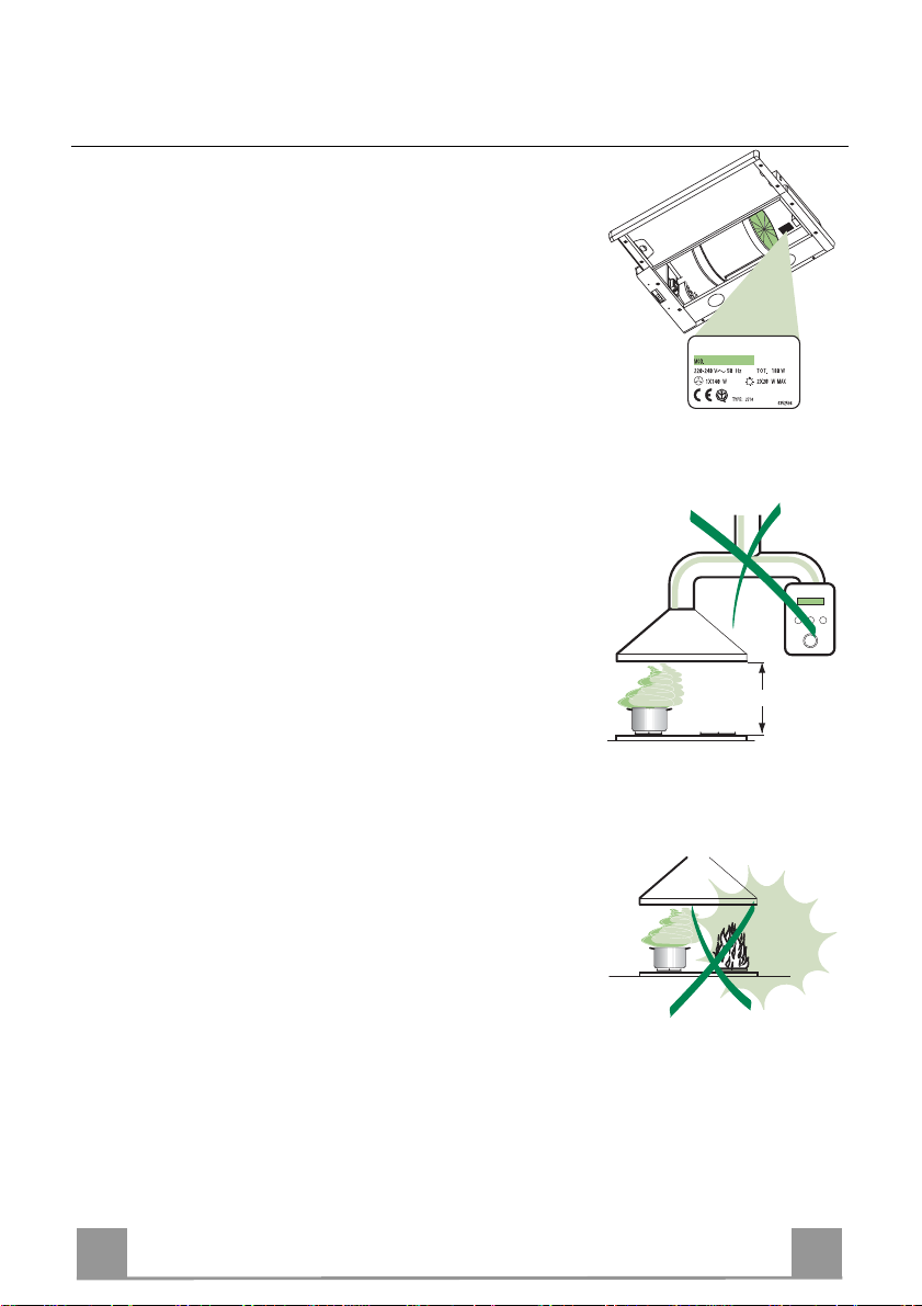
• La distanza minima di sicurezza tra il Piano di cottura e la
Cappa deve essere di 650 mm.
• Verificare che la tensione di rete corrisponda a quella riportata
nella targhetta posta all’interno della Cappa.
• Per Apparecchi in Classe Ia accertarsi che l ’impianto elettrico
domestico garantisca un corretto scarico a terra.
• Collegare la Cappa all’uscita dell’aria aspirata con tubazione di
diametro pari o superiore a 120 mm. Il percorso della tubazione deve essere il più breve possibile.
• Non collegare la Cappa a condotti di scarico dei fumi prodotti
da combustione (caldaie, caminetti, ecc.).
• Nel caso in cui nella stanza vengano utilizzati sia la Cappa che
apparecchi non azionat i da energia elettrica (ad esempio apparecchi utilizzatori di gas), si deve provvedere ad una aerazione
sufficiente dell’ambiente. Se la cucina ne fosse sprovvista, praticare un’apertura che co munichi con l’esterno, per garantire il
richiamo d’aria pulita.
USO
• La Cappa è stata progettata esclusivamente per uso domestico,
per abbattere gli odori della cucina.
• Non fare mai uso improprio della Cappa.
• Non lasciare fiamme libere a forte intensità sotto la Cappa in
funzione.
• Regolare sempre le fiamme in modo da evitare una evidente
fuoriuscita laterale delle stesse rispetto al fondo delle pentole.
• Controllare le friggitrici durante l’uso: l’olio surriscaldato potrebbe infiammarsi.
• La Cappa non deve essere utilizzata da bambini o persone non
abilitate all’uso corretto.
MANUTENZIONE
• Prima di procedere a qualsiasi operazione di manutenzione,
disinserire la Cappa togliendo la spina elettrica o spegnendo
l’interruttore generale.
• Effettuare una scrupolosa e tempestiva manutenzione dei Filtri
secondo gli intervalli consigliati.
• Per la pulizia delle superfici della Cappa è sufficiente utilizzare
un panno umido e detersivo liquido neutro.
7
7
Page 8
IT
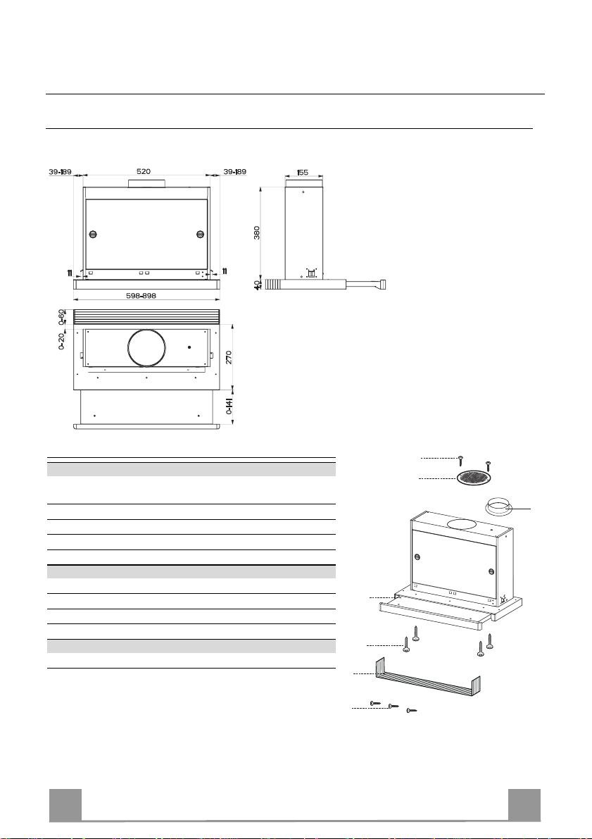
CARATTERISTICHE
Ingombro
Componenti
Rif. Q.tà Componenti di Prodotto
1 1 Corpo Cappa completo di: Comandi, Luce, Gruppo
Ventilatore, Filtri
8 1 Griglia direzionata uscita aria
10a 1 Flangia ø 120
20 1 Profilo chiusura
Rif. Q.tà Componenti di Installazione
12a 4 Viti 3,5 x 16
12e 2 Viti 2,9 x 12,7
12f 3 Viti 2,9 x 9,5
Q.tà Documentazione
1 Libretto Istruzioni
12e
8
10a
1
12a
20
12f
8
8
Page 9
IT
1 3 4
Vr
5
6
7
0
2
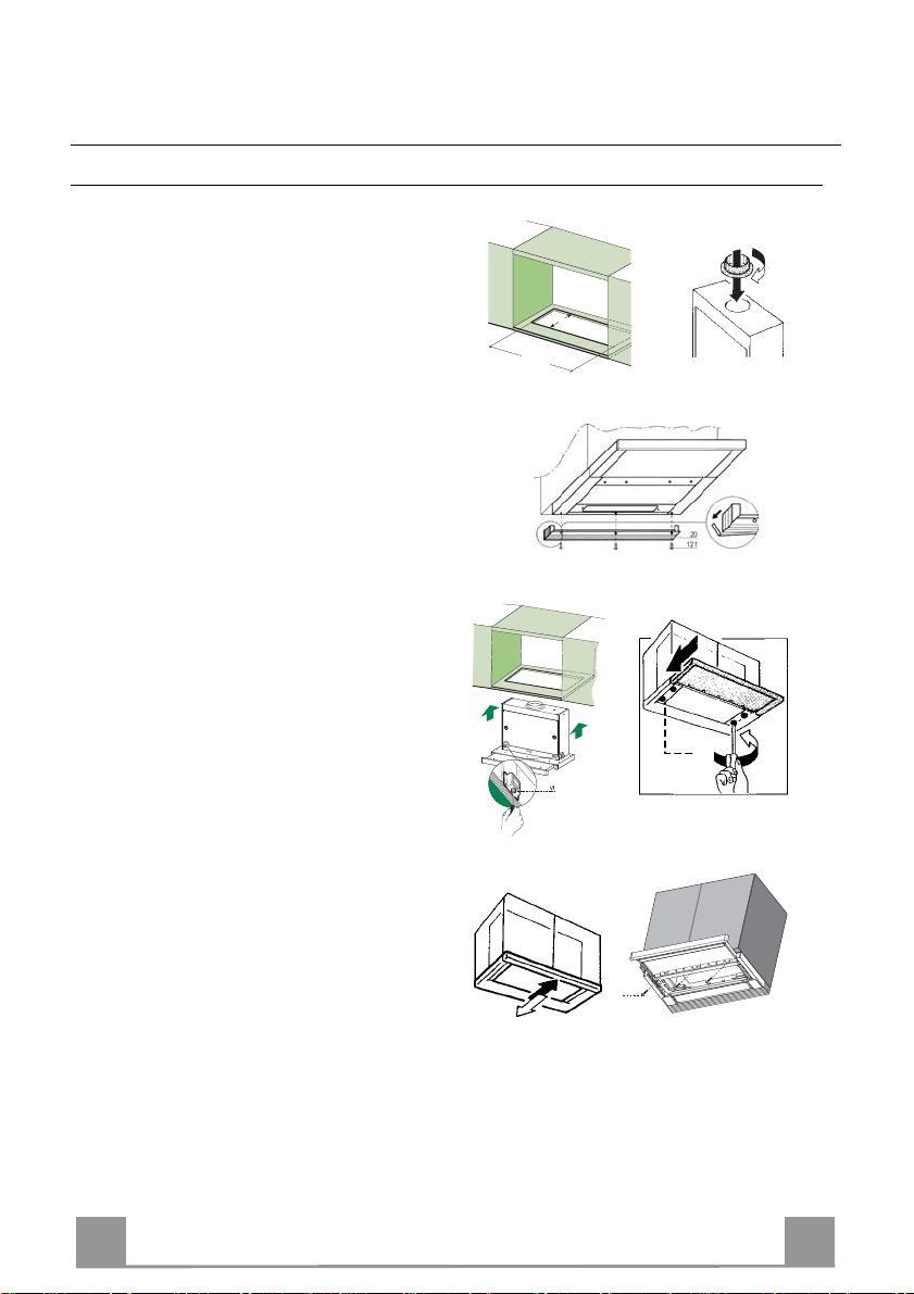
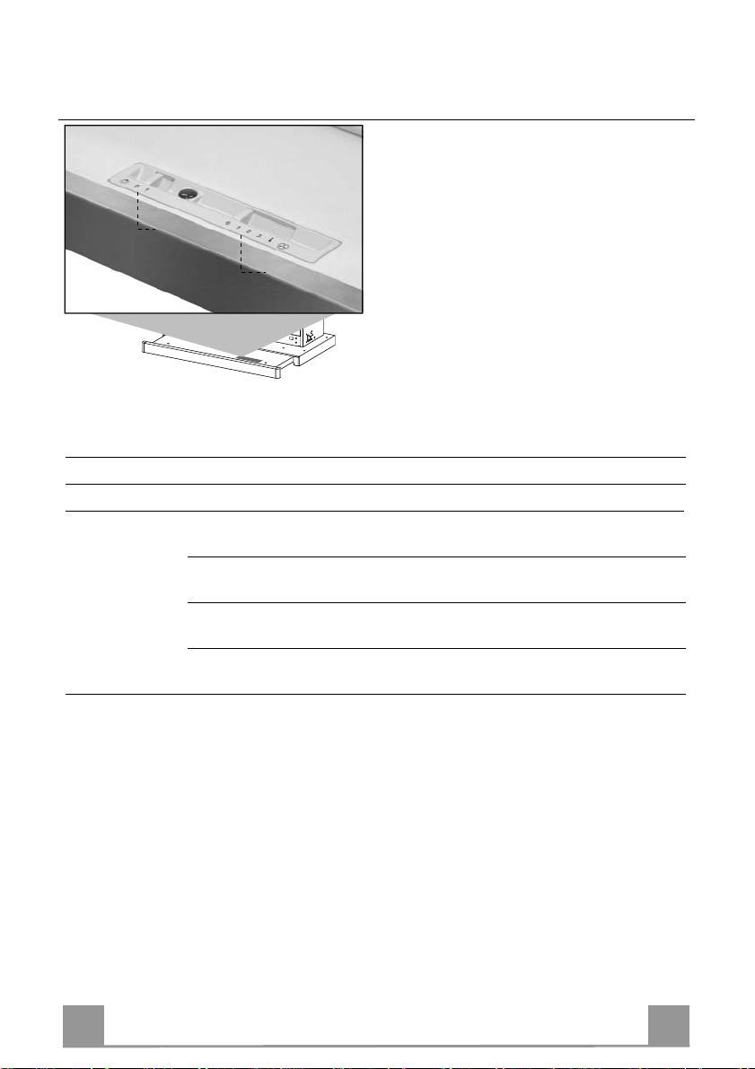
INSTALLAZIONE
Foratura Piano di supporto e Montaggio Cappa
• La Cappa può essere installata direttamente
sul piano inferiore dei Pensili (650 mm min.
dal Piano di Cottura) con i Supporti laterali a
scatto.
• Praticare un incasso sul piano inferiore del
Pensile, come indicato. (fig.1)
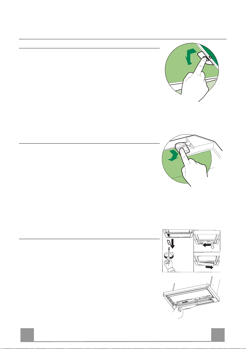
• Inserire la flangia nel foro sup eriore di scarico. (fig.2)
• Avvitare il profilo di chiusura 20 alla parte
posteriore della cappa utilizzando le viti 12f
(2,9 x 9,5) in dotazione. (fig.3)
• Aprire il carrello aspirante.
• Togliere i Filtri Antigrasso uno alla volta,
agendo sugli appositi agganci.
• Richiu dere il carrello aspirante.
• Inserire la Cappa fino ad agganciare i Supporti laterali a scatto. (fig.4)
• Aprire il carrello aspirante.
• Bloccare definitivamente serrando le Viti Vf
dal sotto della Cappa. (fig.4)
• Se è necessario effettuare degli aggiustamenti dell'intero corpo portafiltri, operare
come segue:
• Allentare le quattro viti di regolazione Vr
e richiudere il carrello. (fig.5)
• Traslare l'intero corpo portafiltri fino ad
ottenere l'allineamento desiderato con il
pensile. (fig.6)
• Sempre mantenendo fermo il corpo cappa
estrarre il carrello e serrare le viti di regolazione Vr. (fig.5)
• Ora è possibile fissare definitivamente la
cappa al pensile usando le viti 12a (3,5 x
16) in dotazione. (fig.7)
• Rimontare i Filtri antigrasso.
• Richiu dere il carrello aspirante.
1
162
523
12a
9
9
Page 10
IT 110
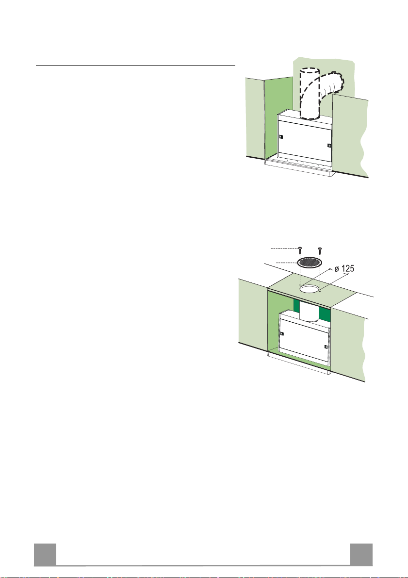
Connessioni
USCITA ARIA VERSIONE ASPIRANTE
Per installazione in Versione Aspirante collegare la
Cappa alla tubazione di uscita per mezzo di un tubo
rigido o flessibile dello stesso diametro della flangia
precedentemente install ata
• Fissare il tubo con adeguate fascette stringitubo. Il
materiale occorrente non è i n dotazione.
• Togliere eventuali Filtri Antiodore al Carbone attivo.
USCITA ARIA VERSIONE FILTRANTE
• Praticare un foro ø 125 mm sull’eventuale Mensola
soprastante la Cappa.
• Inserire la Flangia 10a sull’uscita del Corpo Cappa.
• Collegare la Flangia al foro di uscita sulla Mensola
soprastante la Cappa con un tubo rigido o flessibile di
ø120 mm.
• Fissare il tubo con adeguate fascette stringitubo. Il
materiale occorrente non è i n dotazione.
• Fissare la Griglia direzionata 8 sull’uscita con 2 Viti
12e (2,9 x 12,7) in dotazione.
• Assicurarsi della presenza dei Filtri ant iodore al Carbone attivo.
12e
8
CONNESSIONE ELETTRICA
• Collegare la Cappa all’Alimentazione di Rete interponendo un Interruttore bipolare con apertura dei contatti di almeno 3 mm.
Page 11
IT 111
USO
L
M
Le varie funzioni vengono attivate automaticamente con l’estrazione del carrello. Per spegnere
le funzioni impostate sarà sufficiente richiudere il carrello.
TASTO FUNZIONE
L Luci Accende e spegne l’Impianto di Illuminazione.
M Motore Accende e spegne il motore Aspirazione.
1. Velocità minima, adatta ad un ricambio d’aria continuo particolarmente
silenzioso,in presenza di pochi vapori di cottura.
2. Velocità media, adatta alla maggior parte delle condizioni d’uso, dato
l’ottimo rapporto tra portata d’aria trattata e livello sonoro.
3. Velocità massima, adatta a fronteggiare grandi emissioni di vapore di
cottura,anche per tempi prolungati.
i. Velocità intensiva, adatta a fronteggiare le massime emissioni di fumi di
cottura.
Page 12
IT 112
MANUTENZIONE
Filtri antigrasso
PULIZIA FILTRI ANTI GR A SSO META L L ICI AUTO PO RTAN TI
• Sono lavabili anche in lavastoviglie, e necessitano di essere
lavati ogni 2 mesi circa di utilizzo o più frequentemente, per un
uso particolarmente intenso.
• Estrarre il carrello aspirante.
• Togliere i Filtri uno alla volta, agendo sugli appositi agganci.
• Lavare i Filtri evitando di piegarli, e lasciarli asciugare prima
di rimontarli. (Un’event uale cambiamento del colore dell a superficie del filtro, che potrebbe verificarsi nel tempo, non pregiudica assolutamente l’efficienza dello stesso.)
• Rimontarli facendo attenzione a mantenere la maniglia verso la
parte visibile esterna.
• Chiudere il carrello aspirante.
Filtri antiodore (Versione Filtrante)
SOSTITUZIONE
• Non sono lavabili né rigenerabili, vanno sostituiti ogni 4 mesi
circa di utilizzo o più frequentemente, per un uso particolarmente intenso.
• Estrarre il carrello aspirante.
• Togliere i Filtri Antigrasso
• Rimuovere il Filtro antiodore al Carbone attivo saturo, agendo
sugli appositi agganci.
• Rimontare i Filtri antigrasso.
• Richiu dere il carrello aspirante.
Illuminazione
SOSTITUZIONE LAMPADE
Lampade fluorescenti da 9 W.
• Togliere i terminali metallici che fissano la plafoniera in vetro.
• Far scorrere la plafoniera in vetro verso un lato, fino a liberare
l’estremità opposta. Abbassare leggermente l’estremità libera e
farlo scorrere fino a liberarlo totalmente.
• Sostituire la lampada con una nuova di uguali caratteristiche.
• Rimontare la plafoniera in vetro in sequenza inversa.
Page 13

EN 113
650 mm min.
RECOMMENDATIONS AND SUGGESTIONS
INSTALLATION
• The manufacturer will not be held liable for any damages resulting
from incorrect or improper installation.
• The minimum safety distance between the cooker top and the extractor hood is 650 mm.
• Check that the mains voltage corresponds to that indicated on the
rating plate fixed to the inside of the hood.
• For Class I appliances, check that th e domes tic po wer suppl y gua ran tees adequate earthing.
Connect the extractor to the exhaust flue thro ugh a pipe of minimum
diameter 120 mm. The route of the flue must be as short as possible.
• Do not connect the extractor hood to exhaust ducts carryi ng combustion fumes (boilers, fireplaces, etc.).
• If the extractor is used in conjuncti on with non-electrical appliances
(e.g. gas burning appliances), a suffici ent degree of aeration must be
guaranteed in the room in order to prevent the backflow of exhaust
gas. The kitchen must have an opening communicating directl y with
the open air in order to guarantee the entry of clean air.
USE
• The extractor hood has been designed exclusiv ely for domesti c us e to
eliminate kitchen smells.
• Nev er use the hood for p urposes other than fo r which it has ben designed.
• Never leave high naked flames under the hood when it is in operation.
• Adj ust the flame intensity to direct it onto the bottom of the pan only,
making sure that it does not engulf the sides.
• Deep fat fryers must be continuously monitored during use: overheated oil can burst into flames.
• The hood should not be used by children or persons not instruc ted in
its correct use.
MAINTENANCE
• Switch off or unplug the appliance from the mains supply before carrying out any maintenance work.
• Clean and/or replace the Filters after the specified time period.
• Clean the hood using a damp cloth and a neutral liquid detergent.
Page 14

EN 114
CHARACTERISTICS
Dimensions
Components
Ref. Q.ty Product Components
1 1 Hood Body, complete with: Controls, Light, Blower,
Filters
8 1 Directional Air Outlet grille
10a 1 Flange ø 120 mm
20 1 Closing element
Ref. Q.ty Installation Components
12a 4 Screws 3,5 x 16
12e 2 Screws 2,9 x 12, 7
12f 3 Screws 2,9 x 9,5
Q.ty Documentation
1 Instruction Manual
12e
8
10a
1
12a
20
12f
Page 15

EN 115
1 3 4
Vr
5
6
7
0
2
INSTALLATION
Drilling the Support surface and Fitting the Hood
• The Hood can be fitted directly on the
lower surface of the Wall Units (650 mm
min. above the Cooker Top) using the snapon Side Supports.
• Make an opening on the lower surface of
the Wall Unit, as indicated. (fig.1)
• Choose the correct flange measure basing
on the air outlet diameter and insert it to the
upper air outlet opening. (fig.2)
• Screw the closing profile 20 onto the rear
part of the hood, using the screws 12f (2.9 x
9.5) provided. (fig.3)
• Open the sliding suction panel.
• Remove the metal grease filters one by one
by turning the hooks provided.
• Close the sliding suction panel again.
• Insert the Hood until the snap-on side supports click into place. (fig.4)
• Open the sliding suction panel.
• Lock in position by tightening the screws
Vf from underneath the Hood. (fig.4)
• If necessary, adjust the whole filter holder
unit and proceed as follows:
• Loosen the four adjustment screws Vr
and close the sliding panel again. (fig.5)
• Move the entire filter holder unit until it
is properly aligned with the wall unit.
(fig.6)
• Keeping the hood canopy still, remove
the sliding panel and lock the adjustment
screws again. (fig.5)
• The hood can now be fastened to the wall
unit using the four screws 12a (3.5 x 16)
provided. (fig.7)
• Replace the metal grease filters.
• Close the sliding suction panel again.
1
162
523
12a
Page 16

EN 116
Connections
DUCTING VERSION AIR EXHAUST SYSTEM
When installing the hood in ducting version, a rigid or a
flexible pipe with the diameter corresponding to the
flange diameter is used i n order to conn ect the hood to
the air outlet piping.
• Fix the pipe with an adequate quantity of pipe
clamps (not supplied).
• Remove possible charcoal filters.
RECIRCULATION VERSION AIR OUTLET
• Cut a hole ø 125 mm in any shelf that may be positioned over the hood.
• Insert the flange 10a on the hood body outlet.
• Connect the flange to th e outlet on the shelf over t he
hood using a flexible or rigid pipe ø120 mm.
• Fix the pipe in position using sufficient pipe clamps
(not supplied).
• Fix the directional grille 8 on the recirculation air
outlet using the 2 screws 12e (2,9 x 12,7) provided.
• Ensure that the activated charcoal filters have been
inserted.
12e
8
ELECTRICAL CONNECTION
• Connect the hood to the mains through a two-pole switch having a contact gap of at least 3
mm..
Page 17

EN 117
USE
L
M
By pulling out the sliding panel it is possible to automatically activate all the hood functions.
By simply closing the sliding panel all the functions are switched off.
SWITCH FUNCTIONS
L Light Switches the lighting system on and off
M Motor Switches the extractor motor on and off
1. Low speed , used for a continuo us and silent air change in th e presence
of light cooking vapour.
2. Medium speed, suitable for most operating conditions, thanks to an optimum relation between hood performance and noise.
3. Maximum speed, suitable when the highest cooking vapour emission
has to be eliminated for longer periods.
i. Intensive speed, suitable for the strongest cooking vapours and odours.
Page 18

EN 118
MAINTENANCE
Grease filters
CLEANING METAL CASSETTE GREASE FILTERS
• The filters must be cleaned every 2 months, or more frequently
in case of particularly heavy use of the hood. Filters can be
washed in a dishwasher.
• Pull out the sliding suction panel.
• Remove the filters one by one, after having disconnected the
relative fastening elements.
• Wash the filters, taking care not to bend them. Let them get dry
before refitting them. (The colour of the filter surface may
change throughout the time but this has no influence to the filter efficiency).
• When refitting the filters, make sure that the handle is visible
on the outside.
• Close the sliding suction panel.
Charcoal filter (Recycling version)
REPLACING CHARCOAL FILTERS
• These filters are not washable and cannot be regenerated, and
must be replaced approximately every four months or more
frequently by particularly heavy use.
• Pull out the sliding suction panel.
• Remove the grease filters.
• Remove the saturated carbon filter by releasing the fixing
hooks
• Replace the grease filters.
• Close the sliding suction panel.
Lighting
LIGHT REPLACEMENT
9 W fluorescent lights.
• Remove the metal terminals fixing the glass.
• Slide the glass cover to the right until the left hand is free.
Lower it slightly and slide it to the left to free it completely.
• Replace the light with a new one of the same type and rating.
• Replace the glass cover in reverse order.
Page 19

FR 119
650 mm min.
CONSEILS ET SUGGESTIONS
INSTALLATION
• Le fabricant décline toute responsabilité en cas de dommage dû à
une installation non correcte ou non conforme aux règles de l’art.
• La di stance minimale de sécurité entre le plan de cuisson et l a hotte
doit être de 650 mm au moins.
• Vérifier que la tension du secteur cor respond à l a val eur qui figu re s ur
la plaquette apposée à l’intérieur de la hotte.
• Pour les Appareils appartenant à la Ière Classe, veiller à ce que la
mise à la terre de l’installation électrique domestique ait été effectuée
conformément aux normes en vigueur.
• Connecter la hotte à la sortie d’air aspiré à l’aide d’une tuyauterie
d’un diamètre égal ou supérieur à 120 mm. Le parcours de la
tuyauterie doit être le plus court possible.
• Eviter de connecter la hotte à des conduites d’évacuation de fumées
issues d’une combustion tel que (Chaudière, cheminée, etc…).
• Si vous utilisez des appareils qui ne fonctionnent pas à l’électricité
dans la pièce ou est installée la hotte (par exemple: des appareils
fonc tionnant au gaz), vous devez prévoir une aération suffisante du
milieu. Si la cuisine en est dépou rvue, pratiquez une ouverture qui
communique avec l’extérieur pour garantir l’infiltration de l’air pur.
UTILISATION
• La hotte a é té conçue exclusivement pour l’usage domestique, dans
le but d’éliminer les odeurs de la cuisine.
• Ne jamais utiliser abusivement la hotte.
• Ne pas lai sser les flammes libres à forte intensité quand la hotte es t
en service.
• Toujours régler les flammes de manière à éviter toute sortie latérale
de ces dernières par rapport au fond des marmites.
• Contrôler les friteuses lors de l’utilisation car l’huile surchauffée
pourrait s’enflammer.
• La hotte ne doit pas être utilisée par des enf an ts ou des personnes ne
pouvant pas assurer une utilisation correcte.
ENTRETIEN
• Avant de procéder à toute opération d’entretien, retirer la hotte en
retirant la fiche ou en actionnant l’interrupteur général.
• Effectuer un entretien scrupuleux et en temps dû des Filtres, à la cadence conseillée.
• Pour le nettoyage des surfaces de la hotte, il suffit d’utiliser un chiffon
humide et détersif liquide neutre.
Page 20

FR 220
CARACTERISTIQUES
Encombrement
Composants
Réf. Q.té Composants de Produit
1 1 Corps Hotte équ ipé de: Co mmandes, Lum ière , Groupe
Ventilateur, Filtres
8 1 Grille orientée Sortie de l’Air
10a 1 Flasque ø 120 mm
20 1 Profil fermeture
Réf. Q.té Composants pour l ’installation
12a 4 Vis 3,5 x 16
12e 2 Vis 2,9 x 12,7
12f 3 Vis 2,9 x 9,5
Q.té Documentation
1 Manuel d’instructions
12e
8
10a
1
12a
20
12f
Page 21

FR 221
1 3 4
Vr
5
6
7
0
2
INSTALLATION
Perçage du Plan de support et Montage de la Hotte
• Il est possible d’installer la Hotte directement sur le plan inférieur des Armoires murales (650 mm. min. par rapport aux Plaques de Cuisson), à l’aide des Supports latéraux par encliquetage.
• Percer une ouverture (emboîtage) sur le
plan inférieur de l’Armoire murale, comme
indiqué. (fig.1)
• Insérer la flasque correcte dans le trou supérieur de sortie de l’air. (fig.2)
• Visser le profil de fermeture 20 sur la partie arrière de la hotte, en utilisant les vis 12f
(2,9 x 9,5) fournies avec l’appareil. (fig.3)
• Sortir le chariot aspirant.
• Retirer les Filtres Anti-graisse l’un après
l’autre, en intervenant sur les crochets spécialement prévus.
• Fermer le chariot aspirant.
• Insérer l a Hotte jusqu’à accrocher les Supports latéraux par encliquetage. (fig.4)
• Sortir le chariot aspirant.
• Bloquer définitivement la pièce, en serrant
les Vis Vf depuis le dessous de la Hotte.
(fig.4)
• Si nécessaire, effectu er des ajustements du
corps porte-filtres tout entier, puis suivre
les instructions suivantes:
• Desserrer les quatre vis de réglage Vr et
refermer le chariot. (fig.5)
• Déplacer le corps porte-filtres tout entier,
jusqu’à obtenir l’alignement souhaité de
l’armoire murale. (fig.6)
• Toujours en maintenant bloqué le corps
de la hotte, sortir le chariot et bloquer à
nouveau les vis de réglage. (fig.5)
• Maintenant il est possible de fixer défini-
tivement la hotte contre l’armoire murale
en utilisant les quatre vis 12a (3,5 x 16)
fournies avec l’appareil. (fig.7)
• Remonter les Filtres anti-graisse.
• Sortir le chariot aspirant.
1
162
523
12a
Page 22

FR 222
Branchements
SORTIE AIR VERSION ASPIRANTE
En cas d’installation en version aspirante, brancher la
hotte à la tuyauterie de sortie utilisant un tube rigide ou
flexible avec le même diamètre de la flasque précédemment installée.
• Fixer le tube par des colliers appropriés. Le matériau
nécessaire n’est pas fourni.
• Retirer les éventuels filtres anti-odeur au charbon
actif.
SORTIE AIR VERSION FILTRANTE
• Percer un trou de ø 125 mm. sur l’éventuelle Tablette
qui se trouve au-dessus de la Hotte.
• Insérer le flasque 10a sur la sortie du corps de la
hotte.
• Connecter la Flasque au trou de sortie sur la Tablette
qui se trouve au-dessus de la Hotte, au moyen d’un
tuyau rigide ou flexible de ø120 mm.
• Fixer le tube par des colliers appropriés. Le matériau
nécessaire n’est pas fourni.
• Fixer la Grille orientée 8 sur la sortie de l’air recyclé
à l’aide de 2 Vis 12e (2,9 x 12,7) fournies avec l’ ap-
pareil.
• S’assurer de la présence des filtres anti-odeur au
charbon actif.
12e
8
BRANCHEMENT ELECTRIQUE
• Brancher la hotte sur le secteur en int erposant un interrupteur bipolaire avec o uverture des
contacts d’au moins 3 mm.
Page 23

FR 223
UTILISATION
L
M
Les différentes fonctions de la hotte sont activées automatiquement avec l’ouverture du tiroir.
Pour arrêter les fonctions sélectionnées il suffit de fermer le tiroir.
TOUCHE FUNCTIONS
L Lumières Allume et éteint l’éclairage.
M Moteur Allume et éteint le moteur aspiration
1. Vitesse minimale, pour un rechange d’air permanent particulièrement
silencieux en cas de faibles vapeurs de cuisson.
2. Vitesse moyenne pour la plupart des conditions d’utilisation, étant donné le rapport optimal entre débit d’air traité et niveau sonore.
3. Vitesse maximum, pour faire face aux émissions maximum de vapeur
de cuisson, même pendant des temps prolongés .
i. Vitesse turbo, cette vitesse est conseillée pour de grandes émissions de
va-peurs de cuisson.
Page 24

FR 224
ENTRETIEN
Filtres anti-graisse
NETTOYAGE DES FILTRES ANTI-GRAISSE MÉT ALLIQUES AUTOPOR-
• Les filtres peuvent être également lavés au lave-vaisselle; il
faut les laver tous les 2 mois d’emploi environ, ou bien plus
souvent, en cas d’emploi particulièrement intense.
• Sortir le chariot aspirant.
• Retirer un Filtre à la fois, en intervenant sur les crochets spécialement prévus.
• Laver les Filtres en évitant de les plier, puis laisser sécher
avant de les remonter(L’éventuel changement de couleur de la
surface du filtre, qui pourrait survenir au cours du temps, ne
porte absolument pas préjudice à l’efficacité de celui-ci.).
• Remonter les filtres, en faisant attention à ce que la poignée
soit orientée vers la partie visible externe.
• Fermer le chariot aspirant.
Filtres anti-odeur (Version Filtrante)
• Les filtres ne peuvent pas être lavés ni régénérés; il faut les
remplacer tous les 3-4 mois d’ emploi en viron ou bien plus sou vent, en cas d’emploi particulièrement intense.
• Sortir le chariot aspirant.
• Retirer les Filtres Anti-graisse.
• Retirer le Filtre anti-odeur au Charbon actif saturé, en intervenant sur les crochets spécial ement prévus.
• Remonter les Filtres anti-graisse.
• Refermer le chario t aspirant.
TEURS
REMPLACEMENT
Eclairage
REMPLACEMENT LAMPES
Lampes fluorescentes de 9 W.
• Retirer les étaux métalliques qui fixent le plafonnier en verre.
• Faire glisser le plafonnier en verre sur un côté jusqu’à libérer
l’extrémité opposée. Abaisser légèrement l’extrémité libre et le
faire glisser jusqu’à le libérer totalement.
• Remplacer la lampe par une nouvelle avec les mêmes c aractéristiques.
• Remonter le plafonnier en verre dans la séquence inverse.
Page 25

DE 225
650 mm min.
EMPFEHLUNGEN UND HINWEISE
MONTAGE
• Der Herstell er haftet nicht für Schäden, die auf ein e fehlerhafte und
unsachgemäße Montage zurückzuführen sind.
• Der minimale Sicherheitsabstand zwischen Kochmulde und Haube
muss 650 mm betragen.
• Prüfen, ob die Netzspannung mit dem Wert auf dem im Haubeninneren angebrachten Schild übereinstimmt.
• Bei Geräten der Klasse I ist sic herzustellen, dass die elektri sche Anlage des Wohnhauses über eine vorschriftsmäßige Erdung verfügt.
• Das Anschlussrohr der Haube zur Luftaustrittsöffnung muss einen
Durchmesser von 120 mm oder darüber aufweisen. Der Rohrverl auf
muss so kurz wie möglich sein.
• Die Haube darf an keine Entlüftungsschächte angeschlos sen werden,
in die Verbrennungsgase (Heizkessel, Kamine usw.) geleitet werden.
• Werden im Raum außer der Dunsta bzugshaube andere, nicht elektrisch betriebene (z.B. gasbetri ebene) Geräte verwendet, muss für eine ausreichende Belüftung gesorgt werden. Sollte die Küche diesbezüglich nicht entsprechen, ist an ein er Aussenwand eine Öffn ung anzubringen, die Frischluftzufuhr gewährleistet.
BEDIENUNG
• Die Dunstabzugshaube ist ausschließlich zum Einsatz im privaten
Haushalt und zur Beseitigung von Küchengerüchen vorgesehen.
• Unsachgemäßer Einsatz der Haube ist zu unterlassen.
• Große Flammen bei eingeschalteter Haube niemals unbedeckt lassen.
• Die Intensivität der Flamme ist so zu regulieren, dass sie den Topfboden nicht überragt.
• Frittiergeräte müssen während des Gebrauchs stets beaufsichtigt
werden: überhitztes Öl kann sich entzünden.
• Die Dunstabzugshaube darf von Kin dern ode r Personen, die hi nsichtlich der Bedienung nicht unterwi esen wurden, keinesfalls verwendet
werden.
WARTUNG
• Bev or Wartungsarbeiten du rchgeführt werden, muss die Stromzufuh r
zur Haube unterbrochen werden, indem der Stecker gezogen oder
der Hauptschalter abgeschaltet wird.
• Bei der Filterwartung müssen die vom Herstell er empfohlenen Zeiträume zum Austauschen der Filter genauestens eingehalten werden.
• Zur Reinigung der Haubenfl ächen Wir empfehlen ein feuchtes Tuch
und ein mildes Flüssigreinigungsmittel.
Page 26

DE 226
CHARAKTERISTIKEN
Platzbedarf
Komponenten
Pos. St. Produktkomponenten
1 1 Haubenkörper mit Schaltern, Beleuchtung, Gebläse-
gruppe, Filter
8 1 Luftleitgitter Luftaustritt
10a 1 Flansch ø 120 mm
20 1 Abdeckprofil
Pos. St. Montagekomponenten
12a 4 Schrauben 3,5 x 16
12e 2 Schrauben 2,9 x 12,7
12e 3 Schrauben 2,9 x 9,5
St. Dokumentation
1 Bedienungsanleitung
12e
8
10a
1
12a
20
12f
Page 27

DE 227
1 3 4
Vr
5
6
7
0
2
MONTAGE
Bohren der Trägerplatte und Montage der Dunstabzugshaube
• Die Haube kann direkt an der Unterseite
der Hängeschränke (mindestens 650 mm
von der Kochmulde entfernt) mit seitlichen
Schnapphalterungen fixiert werden.
• An der Unterseite des Hängeschranks, wie
in der Abbildung gezei gt, eine Öffnung anbringen. (Abb.1)
• Abluftstutzen in die obere Luftaustrittsöffnung einstecken. (Abb.2)
• Das Abschlussprofil 20 an der Rückseite
der Haube mit den beiliegenden Schrauben
12f (2,9x9,5) fixieren. (Abb.3)
• Den herausziehbaren Wrasenleitschirm öffnen.
• Die Fettfilter nacheinander entnehmen, indem die entsprechenden Haltevorrichtungen gelöst werden.
• Den herausziehbaren Wrasenleitschirm
wieder schließen.
• Die Haube einschieben, bis die seitlichen
Halterungen einschnappen. (Abb.4)
• Den herausziehbaren Wrasenleitschirm öffnen.
• Die Haube von unten her mit den Schrauben Vf fixieren. (Abb.4)
• Falls erforderlich k, das un ter Teil wie nachstehend beschriebe n ausrichten:
• Die vier Einstellschrauben Vr lockern und
den Wrasenleitschirm wieder schließen.
(Abb.5)
• Den gesamten unteren Korpus verschie-
ben, bis er auf den Oberschrank ausgerichtet ist. (Abb.6)
• Den Haubenkörper festhalten, den Wra-
senleitschirms öffnen und die Einstellschrauben festziehen. (Abb.5)
• Nun kann die Haube am Oberschrank mit
den vier beiliegenden Schrauben 12a (3,5
x 16) fixiert werden. (A bb.7)
• Die Fettfilter wieder montieren.
• Den herausziehbaren Wrasenleitschirm
wieder schließen.
1
162
523
12a
Page 28

DE 228
Anschlüsse
ANSCHLUSS IN ABLUFTVERSION
Für die Installation in Abluftversion die Haube mit Hilfe eines Rohres oder Schlauches vom selben Durchmesser wie der zuvor installierte Flansch an die Auslassleitung anschließen.
• Das Rohr mit geeigneten Rohrschellen fixieren . Das
hierzu erforderliche Material wird nicht mitgeliefert.
• Eventuell vorhandene Aktivkohlefilter entnehmen.
ANSCHLUSS IN UMLUFTVERSION
• In das eventuell über der Haube vorhandene Bord ein
Loch ø 125 mm bohren.
• Den flansch 10a am Haubenaustritt anbringen.
• Den Flansch beim Luftaustritt am Bord oberhalb der
Haube mittels Rohr oder Schlauch ø120 mm anschließen.
• Das Rohr mit geeigneten Rohrschellen fixieren. Das
hierzu erforderliche Material wird nicht mitgeliefert.
• Das Luftleitgitter 8 mit Hilfe von 2 der mitgelieferten
Schrauben 12e (2,9 x 12,7) beim Austritt der rückzuführenden Luft fixieren.
• Sicherstellen, dass der Aktivkohle-Geruchsfilter vorhanden ist.
12e
8
ELEKTROANSCHLUSS
• Bei Anschluss der Haube an das Stromnetz muss ein zweipoliger Schalter mit einem Öffnungsweg von mindestens 3 mm zwischengeschaltet werden.
Page 29

DE 229
BEDIENUNG
L
M
Die verschiedenen Funktionen werden automatisch beim Öffnen des Paneels eingeschaltet.
Um die Funktionen wieder auszuschalten, das Paneel wieder schließen.
SCHALTER FUNKTION
L Beleucht Schaltet die Beleuchtung ein und aus
M Motor Schaltet den Gebläsemotor ein und aus
1. geringste Gebläsestufe, diese Stufe ist für einen ständigen und besonders leisen Luftaustausch bei geringer Kochdunstentwicklung geeignet.
2. mittlere Gebläsestufe, eignet sichaufgrund des guten Verhältnisses zwischen Fördervolumen und Geräuschentwicklung für die meisten Anwendungssituationen.
3. höchste Gebläsestufe, eignet sich für starke Kochdunstentwicklung,
auch über längere Zeit hin .
i. Intensivstufe. Bei sehr starker Kochdunstentwicklung geeignet.
Page 30

DE 330
WARTUNG
Fettfilter
REINIGUNG DER SELBSTTRAGE NDEN METALLFETTFILTER
• Die Filter können auch im Geschirrspüler gereinigt werden und
müssen nach zwei Monaten Betriebszeit oder, bei besonders
intensiver Nutzung, öfter gereinigt werden.
• Den Ansaugschlitten herausziehen.
• Die entsprechenden Haken lösen und die Filter einzeln herausnehmen.
• Die Filter reinigen und vor dem Wiedereinsetzen trocknen lassen, dabei nicht knicken. (Eine eventuelle Verfärbung der Filteroberfläche, zu der es im Laufe der Zeit kommen kann, beeinträchtigt die Wirksamkeit des Filters keinesfalls.)
• Die Filter wieder einsetzen, dabei darauf achten, dass der Griff
nach außen hin sichtbar ist.
• Den Ansaugschlitten wieder schließen.
Geruchsfilter (Umluftversion)
FILTERWECHSEL
• Die Filter lassen sich nicht reinigen oder regenerieren und
müssen nach vier Monaten Betriebszeit oder, bei besonders intensiver Nutzung, öfter ersetzt werden.
• Den Ansaugschlitten herausziehen.
• Die Fettfilter entnehmen
• Die entsprechenden Haken lösen und den gesättigten Aktivkohle-Geruchsfilter entnehmen.
• Die Fettfilter wieder einsetzen.
• Den Ansaugschlitten wieder schließen.
Beleuchtung
AUSTAUSCHEN DER LAMPEN
Leuchtst offlampen zu 9 W.
• Die Metallklemmen entfernen, die die gläserne Lampenabdeckung halten.
• Die gläserne Lampenabdeckung zur Seite gleiten lassen, bis
die gegenüberliegende Seite frei liegt. Die freie Seite leicht
nach unten ziehen und die Lampenabdeckun g zur Seite gleiten
lassen, bis die Beleuchtung ganz frei liegt.
• Die Lampe durch eine neue mit den selben Eigenschaften ersetzen.
• Die gläserne Lampenabdeckung in umgekehrter Reihenfolge
wieder anbringen.
Page 31

TR 331
650 mm min.
TAVSIYELER VE ÖNERILER
MONTAJ
• Yalnιş veya eksik montajdan doğan herhangi bir zararιn s orumluluğu üreticiye ait değildir.
• Davlumbaz ile pişirici cihazιn ocak kιsmι arasιndaki minimum
güvenlik mesafesi 650 mm.dir.
• Besleme voltajιnιn, davlumbaz içerisine yerleştirilen bilgi etiketinde belirtilenle aynι olup olmadιğιnι kontrol edin.
• Sιnιf I elektrikli aletleri için, güç kaynağιnιn yeterli topraklamayι
sağlayιp sağlamadιğιnι kontrol edin. Minimum 120 mm çapιnda
bir boru yoluyla davlumbazι çιkιş bacasιna bağlayιn. Baca
bağlantιsι mümkün oldu- ğunca kιsa olmalιdιr.
• Davlum baz borusunu yanιcι duman taşιyan baca deliğine (buhar
kazanι, şömine, vb.) bağlamayιn.
• Davlumbazιn elektrikle çalιşmayan aletlerle (örneğin; gazlι cihazlar) bağιntιlι olarak kullanιlmamasι halinde çιkιş gazιnιn geri t epmesini önlemek amacιyla odada yeterli bir havalandιrma
sağlanmalιdιr.Temiz hava girişini temin etmek için mutfakta doğ-
rudan dιşarιya açιlan bir açιklιk bulunmalιdιr.
KULLANIM
• Davlumbaz mutfaktaki kokularιn emilmesi amacιyla evlerde
kullanιm için tasarlanmιştιr.Ticari ve endüstriyel amaçlar için
kullanmayιnιz.
• Davlumbazι tasarlandιğι amaçlarιn dιşιnda kesinlikle
kullanmayιnιz.
• Davlumbaz çalιşιrken altιnda kesinlikle yüksek çιplak ateş
bιrakmayιn.
• Alev yoğunluğunu doğrudan tencerenin altιnda kalacak şekilde
ayarlayιn, kenarlarιnι sarmadιğιndan emin olun.
• Yağda kιzartma tavalarιnι kullanιrken sürekli olarak takip edin:
fazla ιsιnan yağ tutuşabilir.
• Davlum baz çocuklar veya doğru kullanιm konusunda bilgisi olmayan kişiler tarafιndan kullanιlmamalιdιr.
BAKIM
• Herhangi bir bakιm işlemini gerçekleştirmeden önce davlumbazι
kapatιn veya fişini çιkarιn.
• Filtreleri belirtilen zamanlarda temizleyin ve / veya değiştirin.
• Cihazι nemli bir bez ve nötr bir sιvι deterjan kullanarak temizleyin.
Page 32

TR 332
ÖZELLIKLER
Boyutlar
Bileşenler
Ref. Adet Ürün Bileşenleri
1 1 Kumandaları, Işığı, Vantilatör Grubu ve Filtreleri ile
komple Baca Gövdesi
8 1 Hava tahliye ız garası
10a 1 Flanş ø 120
20 1 Kapak profili
Ref.. Adet Montaj Bileşenleri
12a 4 Vida 3,5 x 16
12e 2 Vida 2,9 x 12,7
12f 3 Vida 2,9 x 9,5
Adet Belgeler
1 Kullanım Kılavuzu
12e
8
10a
1
12a
20
12f
Page 33

TR 333
1 3 4
Vr
5
6
7
0
2
MONTAJ
Destek Düzlemi Delme Planı ve Baca Montajı
• Yan kilit destekleri aracılığı ile bacanın
doğrudan asma dolapların alt kısmına monte edilmesi mümkündür (ocak seviyesinin
en az 650 mm yukarısında).
• Gösterildiği gibi, dolabın alt kısmına bir
alan açılır (Şekil 1).
• Flanşı üst tahliye deliğine yerleştirin (Şekil
2).
• Kapak profilini 20 12f vidalarını (2,9 x 9,5)
kullanarak bacanın arka kısmına vidalayınız (Şekil 3).
• Emme grubunu açın.
• Kilitlerini açmak sureti ile yağ önleyici filtreleri teker teker sökün.
• Emme grubunu kapatın.
• Yan kilit destekler kapanıncaya kadar bacayı itin (Şekil 4).
• Emme grubunu açın.
• Bacanın alt kısmınd aki Vf vidaları sıkarak
sabitleyin (Şekil 4).
• Eğer filtrelerin bulunduğu kısmın ayarlanması gerekiyorsa, aşağıda i zah ed ild iği üzere hareket edin:
• Dört adet Vr vidasını gevşetin ve grubu
kapatın (Şekli 5).
• Filtreleri içeren kısmı ileri veya geri kay-
dırarak dolap ile istenilen hizaya getirin.
(Şekil.6).
• Baca grubunu sabit tutarak grubu çıkarın
ve Vr ayar vidalarını (2,9 x 9,5) sıkın
(Şekil.5).
• 12a vidalarını (3,5 x 16) ku llanarak baca-
yı dolaba sabitleyin (Şekil 7).
• Yağ önleyici filtreleri yerine takın.
• Emme grubunu kapatın. r
1
162
523
12a
Page 34

TR 334
Bağlantılar
EMME MODELİ HAVA TAHLİYESİ
Emme modelini mont e etmek için bacayı tahliye bacasına bağlayın. Ara parça olarak, genişliği önceden monte edilen flanşın çapı ile aynı olan esnek veya esnek
olmayan bir hortum kullanın.
• Hortumu uygun kelepçeler aracılığı ile sıkın. Gereken malzemeler dahil değildir.
• Aktif karbonlu koku önleyici filtreler var ise bunları
çıkarın.
FİLTRE MODELİNDE HAVA TAHLİYESİ
• Bacanın üstünde yer alan o lası rafa 125 mm çapında
bir delik açın.
• Baca gövdesinin tahliye deliğine 10a flanşını yerleş-
tirin.
• Flanş ile bacanın üst kısmınd a yer alan rafa açılmış
olan deliği 120 mm çapında esnek veya esnek olmayan bir boru il e birleştirin.
• Hortumu uygun kelepçeler ile sabitleyin. Gerekli
malzeme dahil değildir.
• 8 no.lu yönlü ızgarayı 2 adet 12e vidası (2,9 x 12,7)
(dahildir) kullanarak çıkışa monte edin.
• Aktif karbonlu koku önleyici filtrelerin yerlerinde
olmalarına dikkat edin.
12e
8
ELEKTRIK BAĞLANTISI
• Davlumbazι, temas noktalarι arasιnda 3 mm açιklιk olan çift kutuplu bir anahtar üzerinden
elektrik şebekesine b ağlayιn.
Page 35

TR 335
KULLANIM
L
M
Şaryonun dışarıya doğru kaydırılması ile farklı fonksiyonlar aktif hale gelmektedir. Bunların
kapatılması için şaryonun yere kaydırılması yeterli olacaktır.
DÜĞME İŞLEVİ
L Işıklar Işıklandırma sistemini açar ve kapat ır.
M Moto r Havalandırma motorunu açar ve kapatır.
1. Minimum hız; sessiz bir şekilde sürekli hava değişimini sağlar; az du-
manlı durumlarda kullanılır.
2. Ortalama hız; işlenen hava miktarı ile çıkan ses arasındaki oranın mükemmelliği açısından pişirme şartlarının çoğuna uygundur.
3. Azami hız; çokça buhar meydana getiren pişirme şartına uygun olup
uzun süreler boyunca devrede kalabilir.
i. Yoğun hız; azami düzeydeki pişirme buharları ile baş etmek için.
Page 36

TR 336
lanıldıktan sonra veya özellikle yoğun kullanım söz konusu ise
BAKIM
Yağ filtreleri
MONTELİ METAL YAĞ FİLTRELERİNİN TEMİZLİĞİ
• Bulaşık makinesinde yıkanabilirler, 2 ayda bir veya özellikle
yoğun kullanım söz konusu ise daha sık yıkanmalıdırlar.
• Emme arabasını çıkartın.
• Kancalarına bastırmak sureti ile filtreleri teker teker çıkartın.
• Filtreleri katlamadan yıkayın ve monte etmeden önce kurutun.
(Zamanla filtre yüzeyinde meydana gelebilecek ren k değişikli-
ği filtrenin etkinliğinde kesinlikle bir azalmaya neden olmaz.)
• Kolu dışarıdan görülen tarafta kalaca k şekilde yeniden monte
edin.
• Emme arabasını kapatın.
Koku filtreleri (Filtreli Versiyon)
DEĞİŞTİRME
• Yıkanmazlar ve yen id en kul lan ıl amazlar, yakla şık her 4 ay kul-
değiştirilirler.
• Emme arabasını çıkartın.
• Yağ filtrelerini çıkartın.
• Kancalarından bastırarak koku filtresini aktif satüre karbondan
çıkartın.
• Yağ filtresini yerine takın.
• Emme arabasını kapatın.
Işıklandırma
AMPULLERİN DEĞİŞTİRİLMESİ
9W fluoresan ampuller
• Cam kapağı yerinde tutan metalik bağlantıları çıkarın.
• Kapağı bir tarafa doğru kaydırmak sureti ile diğer ucun serbest
kalmasını sağlayın. Serbest ucu hafifçe aşağıya indirerek ta-
mamen serbest kalana kadar kaydırın.
• Ampulü aynı özelliklere sahip bir yenisi ile değiştirin.
• Yukarıda bahse konu işlemi tersine uygulayarak cam kapağı
kapatın.
Page 37

Page 38

Page 39

Page 40

Dir. 89/336/CEE
73/23/CEE
93/68/CEE
Il simbolo sul prodotto o sull a co nfezi on e indi ca c he il prodo tto no n dev e ess ere c ons id era to co me un n ormal e r ifi uto dom es tic o,
ma deve essere port at o nel punt o di r acc olta appr opr iat o per il ric icl aggio di ap par ecchi atur e el ettr ich e ed el ettr oni ch e. Prov v ede nd o a
smaltire ques to pr od otto i n m odo a ppr opr iat o, s i contr ib uisc e a ev it are pote nzi ali c ons egu enz e ne gati ve per l’ ambi en te e p er l a salute,
che potrebber o d er i v are da uno smaltimento i n a deguato del prodotto. Per informazioni pi ù de ttagliate sul rici c l aggi o di questo prodotto,
contattare l’ufficio comunale, il servizio locale di smaltimento rifiuti o il negozio in cui è sta to acquistato il prodotto.
The symbol on the product or o n i ts pac kaging indicates tha t thi s pr o d uc t m ay n ot be treated as househol d w as t e. Instead it shall
be handed over to the appl icable col lection p oint for t he recycli ng of electr ical and el ectronic equipment . By ensurin g this product is
disposed of correctly, you will help prevent potential negative consequences for the environment and human health, which could otherwise be caused by inap propr iat e wast e ha ndl ing of this pro duc t. For mor e det ail ed inf ormati o n about recy cli ng of this pro duc t, ple ase
contact your local city office, your household waste disposal service or the shop where you purchased the product.
Le symbole sur le produit ou s on em bal la ge in diqu e que c e pro dui t ne peut ê tre tr aité c omm e déc he t mén ager. Il doi t plut ôt être
remis au point de ramassage concerné, se chargeant du recyclage du matériel électrique et électronique. En vous assurant que ce
produit est éli miné cor rectem ent, v ous fav orise z la prév entio n des cons équ ences né gativ es po ur l’env ironnem ent et l a sant é humaine
qui, sinon, serai e nt le résultat d’un traitement inapproprié d es d éc h ets d e c e produit. Pour obteni r pl us de dé tai l s s ur l e rec yclage de ce
produit, veuillez prendre contact avec le bureau municipal de votre région, votre service d’élimination des déchets ménagers ou le
magasin où vous av ez acheté le produit.
Das Symbol auf dem Produk t oder s einer V erpac kung weist dar auf hi n, dass di eses Prod ukt ni cht als nor maler Haus halts abfall
zu behandeln is t, so nder n an ei nem Sam mel pu nkt f ür das Rec ycl ing v on elek tri sc hen und elek tr onisc he n G eräte n abg egeb en w er den
muss. Durch Ihren Beitrag zum k orrekten Entsorgen dieses Produkts sc hützen Sie die Umwel t un d die Gesundheit I hr er M i tm enschen.
Umwelt und Ges undheit werden durc h falsches Entsorge n gefährdet. Weitere Informationen über das Recycling dieses Pr odukts
erhalten Sie von Ihrem Rathaus, Ihrer Müllabfuhr oder dem Geschäft, in dem Sie das Produkt gekauft haben.
Ürün veya paketi üz erindeki sembolü, bu ürünün nor mal bir evsel atık olar ak görülmemesi ve bu tip elektrikli veya elektronik
cihazların at ıldığı dönüşümlü toplama nokt aları na terk edil mesi gerekti ğine işaret eder . Bu ür ünü gerek tiği gibi eli mine etm e kur allar ına
uyarsanız çevre ve insan sağlığı üzerindeki olumsuz etkilerini bert araf etmeye katkı s ağlamış olursunuz. Bu ür ünün geri dön üşüm
koşulları hakkında daha ayrıntılı bilgi için hudutları içinde bulunduğunuz belediyenin ilgili diaresine, atık yoketme servisine veya ürünün
satıcısına danışınız.
Franke S.p.a.
Via Pignolini,2
37019 Peschiera d el Garda (VR)
www.franke.it
436003019_ver2
 Loading...