

Franke Consumer Products FSL 905 BK-XS ECS, FSL 905 WH-XS ECS User Manual

GB
SE
NO
DK
FI
Instructions for use and installation
Cooker Hood
Handbok för installation, användning och underhăll
Spisfläkt
Håndbok for installasjon bruk og vedlikehold
Kjøkkenvifte
Betjenings- og installationsvejledning
Emhætte
Asennus-, käyttö- ja hoito-opas
Liesituuletin
FSL 905 BK/XS ECS
FSL 905 WH/XS ECS

INDEX
RECOMMENDATIONS AND SUGGESTIONS.....................................................................................................................3
CHARACTERISTICS.............................................................................................................................................................4
INSTALLATION...................................................................................................................................................................... 6
USE........................................................................................................................................................................................9
MAINTENANCE...................................................................................................................................................................10
EASY CLEANING TM..........................................................................................................................................................11
EN
INNEHÅLL
REKOMMENDATIONER OCH TIPS...................................................................................................................................14
EGENSKAPER.....................................................................................................................................................................15
INSTALLATION.................................................................................................................................................................... 17
ANVÄNDING........................................................................................................................................................................20
UNDERHÅLL........................................................................................................................................................................21
EASY CLEANING TM.......................................................................................................................................................... 22
SE
INNHOLD
ANBEFALINGER OG FORSLAG........................................................................................................................................ 25
EGENSKAPER.....................................................................................................................................................................26
INSTALLASJON................................................................................................................................................................... 28
BRUK ................................................................................................................................................................................... 31
VEDLIKEHOLD.................................................................................................................................................................... 32
EASY CLEANING TM.......................................................................................................................................................... 33
NO
INDHOLD
RÅD OG ANVISNINGER..................................................................................................................................................... 36
APPARATBESKRIVELSE ................................................................................................................................................... 37
INSTALLATION.................................................................................................................................................................... 39
BRUG................................................................................................................................................................................... 42
VEDLIGEHOLDELSE.......................................................................................................................................................... 43
EASY CLEANING TM.......................................................................................................................................................... 44
DK
SISÄLTÖ
OHJEET JA SUOSITUKSET............................................................................................................................................... 47
MITAT JA OSAT .................................................................................................................................................................. 48
ASENNUS............................................................................................................................................................................50
KÄYTTÖ............................................................................................................................................................................... 53
HUOLTO .............................................................................................................................................................................. 54
EASY CLEANING TM.......................................................................................................................................................... 55
FI
2
2
RECOMMENDATIONS AND SUGGESTIONS
The Instructions for Use apply to several versions of this appliance. Accord-
ingly, you may find descriptions of individual features that do not apply to
your specific appliance.
INSTALLATION
• The manufacturer will not be held liable for any damages resulting from incorrect or improper installation.
• The minimum safety distance between the cooker top and the extractor
hood is 650 mm (some models can be installed at a lower height, please refer to the paragraphs on working dimensions and installation).
• Check that the mains voltage corresponds to that indicated on the rating
plate fixed to the inside of the hood.
• For Class I appliances, check that the domestic power supply guarantees
adequate earthing.
Connect the extractor to the exhaust flue through a pipe of minimum diame-
ter 120 mm. The route of the flue must be as short as possible.
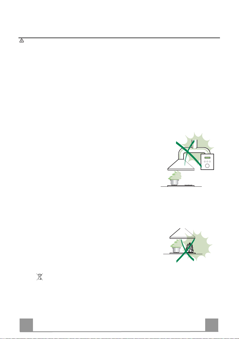
• Do not connect the extractor hood to exhaust ducts carrying combustion
fumes (boilers, fireplaces, etc.).
• If the extractor is used in conjunction with non-electrical appliances (e.g. gas
burning appliances), a sufficient degree of aeration must be guaranteed in
the room in order to prevent the backflow of exhaust gas. The kitchen must
have an opening communicating directly with the open air in order to
guarantee the entry of clean air.
USE
• The extractor hood has been designed exclusively for domesti c use to eliminate kitchen smells.
• Never use the hood for purposes other than for which it has been designed.
• Never leave high naked flames under the hood when it is in operation.
• Adjust the flame intensity to direct it onto the bottom of the pan only, making
sure that it does not engulf the sides.
• Deep fat fr yers must be continuously monitored during use: overheated oil
can burst into flames.
• Do not flambè under the range hood; risk of fire
• This appliance is not intended for use by persons (including children) with
reduced physical, sensory or mental capabilities, or lack of experience and
knowledge, unless they have been given supervision or instruction concerning use of the appliance by a person responsible for their safety.
• Children should be supervised to ensure that they do not play with the appliance.
MAINTENANCE
• Switch off or unplug the appliance from the mains supply before carrying out
any maintenance work.
• Clean and/or replace the Filters after the specified time period (Fire hazard).
• Clean the hood using a damp cloth and a neutral liquid detergent.
The symbol on the product or on its packaging indicates that this product may not be treated
as household waste. Inst ead it shall be handed over t o the applicable collection point for the
recycling of electrical and electr on ic e quipm e nt. By ens ur ing t his pr od uct is disp os ed of c orr ect ly,
you will help prevent potent ial negative consequences for t he environment and human healt h,
which could otherwise be caused by inappropriate waste handling of this product. For more
detailed information about recycling of this product, please contact your local city office, your
household waste disposal service or the shop where you purchased the product.
EN
3
3
1
2.1
2.2
2
12c
12a
7.2.1 11
11
12a
9
7.3
10
14.1
15
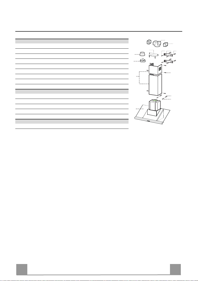
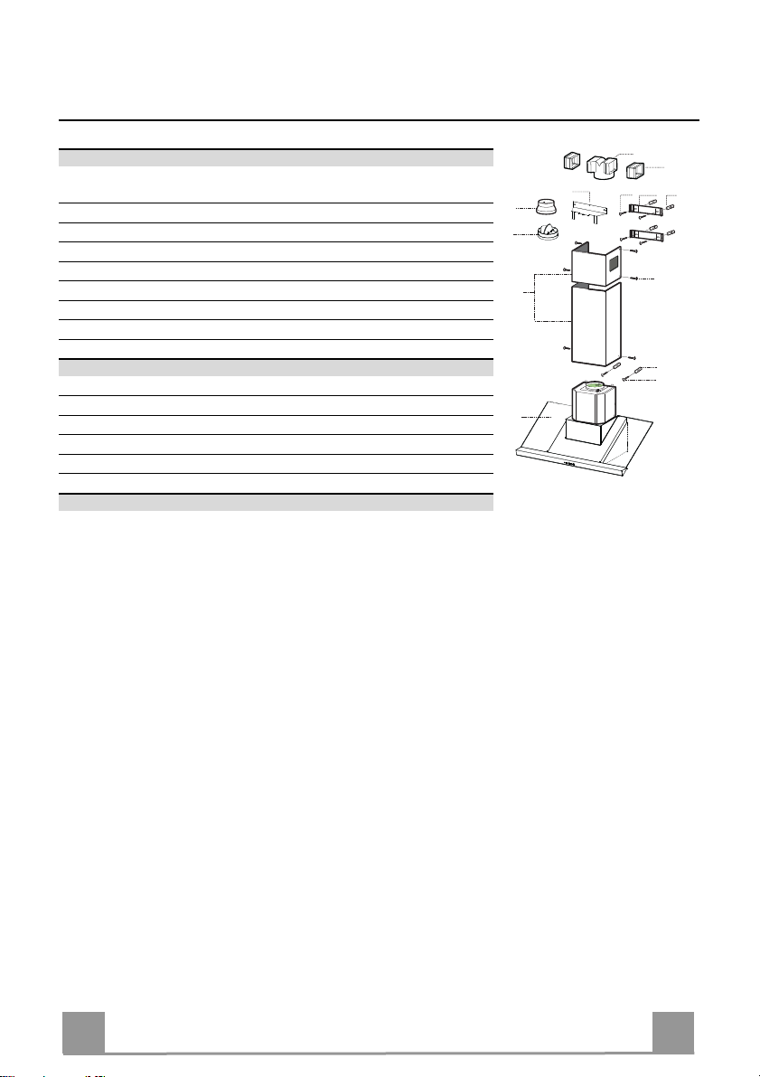
CHARACTERISTICS
Components
Ref. Q.ty Product Components
1 1 Hood Body, complete with: Controls, Light, Blower, Filters
2 1 Telescopic Chimney comprising:
2.1 1 Upper Section
2.2 1 Lower Section
9 1 Reducer Flange ø 150-120 mm
10 1 Damper ø 150
14.1 2 Air Outlet Connection Extension
15 1 Air Outlet Connection
Ref. Q.ty Installation Components
7.2.1 2 Upper Chimney Section Fixing Brackets
7.3 1 Air Outlet Connection Support
11 6 Wall Plugs
12a 6 Screws 4,2 x 44,4
12c 6 Screws 2,9 x 9,5
Q.ty Documentation
1 Instruction Manual
EN
4
4

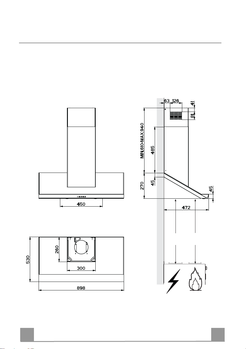
Dimensions
EN
Min.
650mm
Min.
650mm
5
5
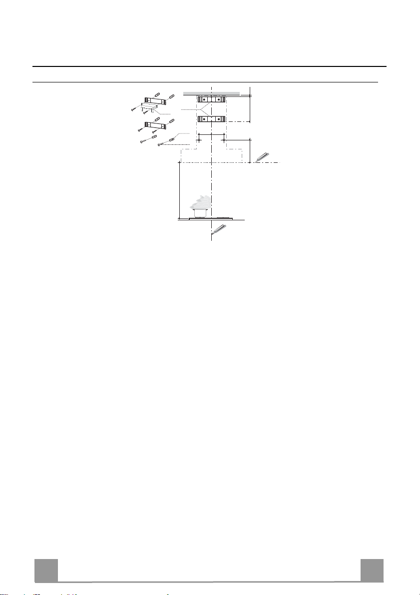
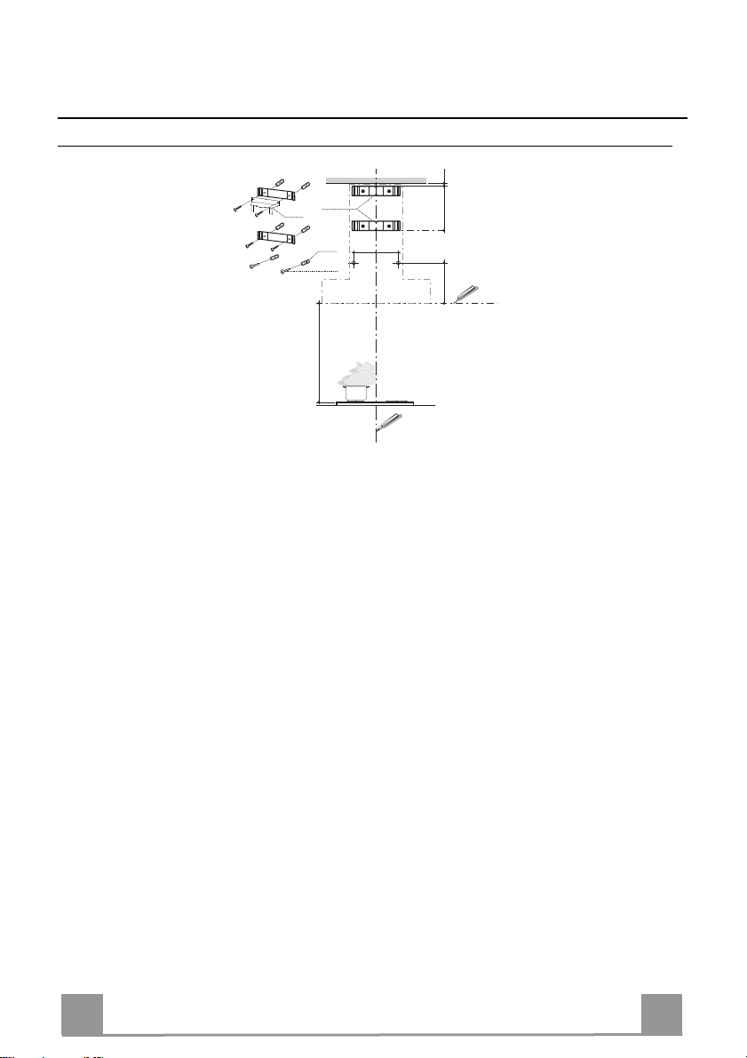
INSTALLATION
Wall drilling and bracket fixing
1÷2
7.2.1
7.3
11
116
116
12a
650 min.
Wall marking:
• Draw a vertical line on the supporting wall up to the c eiling, or as high as practical, at the centre of the
area in which the hood will be installed.
• Draw a horizontal line at 650 mm above the hob.
• Place bracket 7.2.1 on the wall as shown about 1-2 mm from the ceiling or upper limit aligning the centre (notch) with the vertical reference line.
• Mark the wall at the centres of the holes in the bracket.
• Place bracket 7.2.1 on the wall as shown at X mm below the first bracket (X = height of the upper
chimney section supplied), aligning the centre (notch) with the vertical line.
• Mark the wall at the centres of the holes in the bracket.
• Mark a reference point as indicated at 116 mm from the vertical reference line and 535 mm above the
horizontal reference line.
• Repeat this operation on the other side.
• Drill ø 8 mm holes at all the centre points marked.
• Insert the wall plugs 11 in the holes.
• Fix the lower bracket 7.2.1 using the 12a screws (4,2 x 44,4) supplied.
• Fix the upper bracket 7.2.1 and the air outlet connection support 7.3 together using the 2 screws 12a
(4,2 x 44,4) supplied.
• Insert the two scre ws 12a (4,2 x 44,4) supplied in the hood body fixing holes, leaving a gap of 5-6 mm
between the wall and the head of the screw.
X
535
EN
6
6

12a
Vr
9
ø 120ø 150
10
10
ø 150
15
14.1
7.3
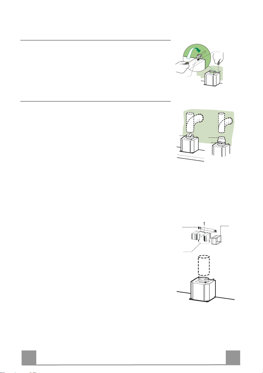
Mounting the hood body
• Before attaching the hood body, tighten the two screws Vr located on the hood body mounting points.
• Hook the hood body onto the screws 12a.
• Fully tighten the support screws 12a.
• Adjust the screws Vr to level the hood body.
Connections
DUCTED VERSION AIR EXHAUST SYSTEM
When installing the ducted version, connect the hood to the
chimney using either a flexible or rigid pipe ø 150 or 120mm, the
choice of which is left to the installer.
To install a ø 150 pipe
• To install the dumper 10
• Fix the pipe in position using sufficient pipe clamps (not supplied).
To install a ø 120 pipe
• To install a ø 120 mm air exhaust connection, insert the reducer flange 9 on the dumper 10.
• Fix the pipe in position using sufficient pipe clamps (not supplied).
• Remove any activated charcoal filters.
RECIRCULATION VERSION AIR OUTLET
• Insert the connection extension pieces laterally 14.1 in connection 15.
• Insert the Connector 15 into the Support bracket 7.3 and fix it
with a screw.
• Make sure that the outlet of the extension pieces 14.1 is horizontally and vertically aligned with the chimney outlets.
• Connect the air outlet connection 15 to the hood body outlet
using either a flexible or rigid pipe ø 150 mm, the choice of
which is left to the installer.
• Ensure that the activated charcoal filters have been inserted.
EN
7
7
12c
12c
12c
2.1
2.2
2
7.2.1
1
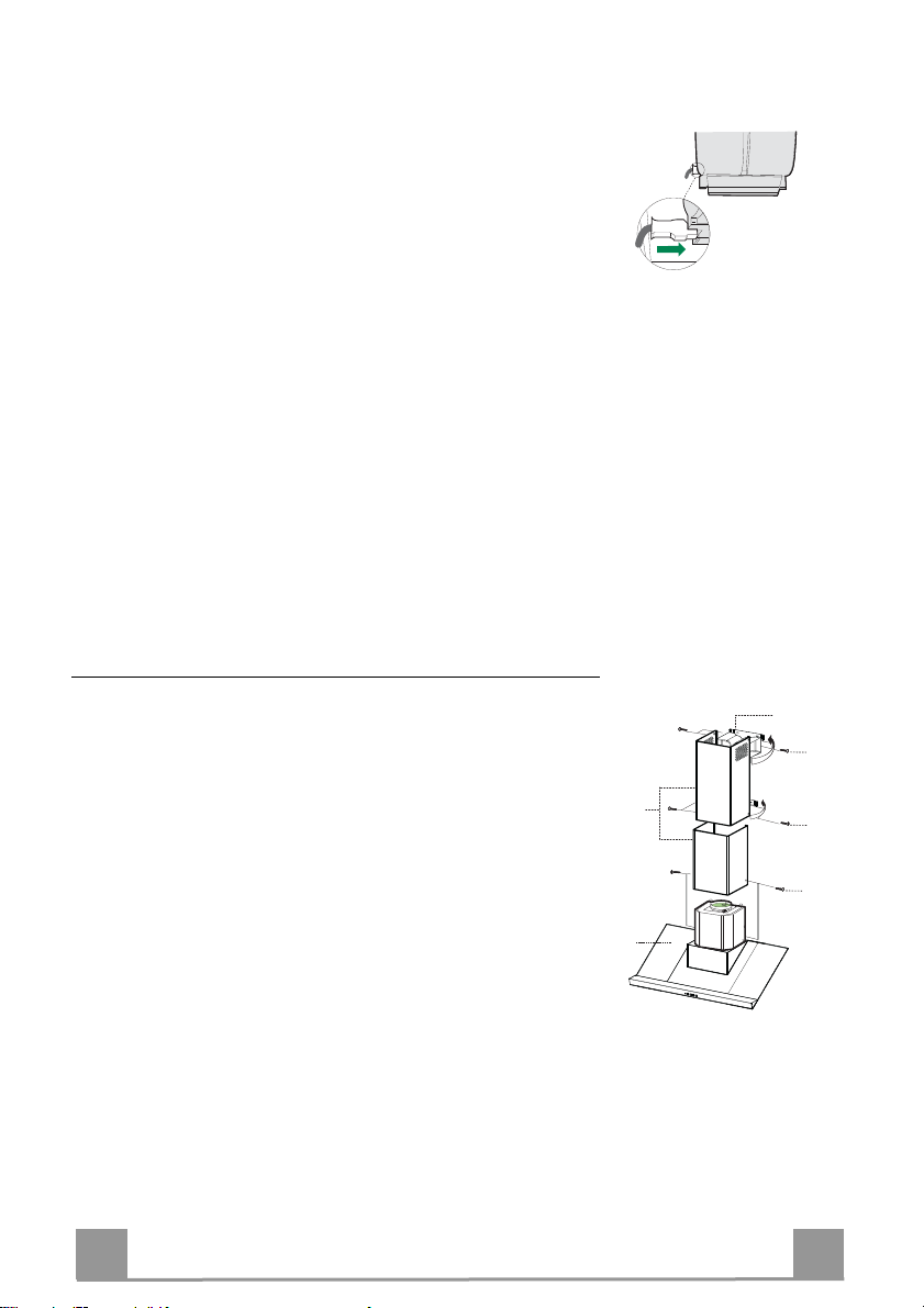
ELECTRICAL CONNECTION
• Connect the hood to the mains through a two-pole switch having a contact gap of at least 3 mm.
• Remove the grease filters (see paragraph Maintenance) being
sure that the connector of the feeding cable is correctly inserted
in the socket placed on the side of the fan.
Flue assembly
Upper exhaust flue
• Slightly widen the two sides of the upper flue and hook them
behind the brackets 7.2.1, making sure that they are well
seated.
• Secure the sides to the brackets by using the 4 screws 12c (2,9
x 9,5) supplied.
• Make sure that the outlet of the extensions pieces is aligned
with the chimney outlets.
Lower exhaust flue
• Slightly widen the two sides of the flue and hook them between the upper flue and the wall, making sure that they are
well seated.
• Fix the lower part laterally to the hood body by using the 2
screws 12c (2,9 x 9,5) supplied.
EN
8
8
USE
T1
T2
T3
L
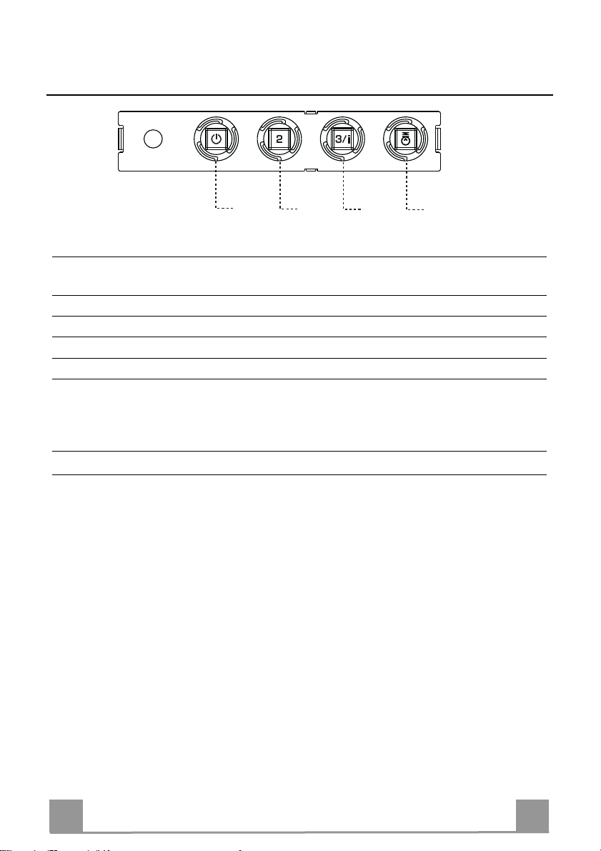
Control panel
BUTTON LED FUNCTIONS
T1 Speed On Turns the Motor on at Speed one.
Turns the Motor off.
T2 Speed On Turns the Motor on at Speed two.
T3 Speed Fixed When pressed briefly, turns the Motor on at Speed three.
Flashing Pressed for 2 Seconds.
Activates Speed four with a timer set to 10 minutes, after
which it returns to the speed that was set previously. Suitable
to deal with maximum levels of cooking fumes.
L Light Turns the Lighting System on and off.
Warning: Button T1 turns the motor off, after first passing to speed one.
EN
9
9
MAINTENANCE
Grease filters
CLEANING METAL SELF- SUPPORTING GREASE FILTERS
• The filters must be cleaned every 2 months of operation, or more frequently for particularly heavy usage,
and can be washed in a dishwasher.
• Remove the filters one at a time by pushing them towards the back of the group and pulling down at the
same time.
• Wash the filters, taking care not to bend them. Allow
them to dry before refitting.
• When refitting the filters, make sure that the handle
is visible on the outside.
Activated charcoal filter (Recirculation version)
REPLACING THE ACTIVATED CHARCOAL FILTER
• The filter is not washable and cannot be regenerated,
and must be replaced approximately every 4 months
of operation, or more frequently for particularly
heavy usage.
• Remove the metal grease filters.
• Remove the saturated activated carbon filter by releasing the fixing hooks.
• Fit the new filter by hooking it into its seating.
• Refit the metal grease filters.
Lighting
LIGHT REPLACEMENT
20 W halogen light.
• Extract the lamp from the lamp holder by pulling
gently.
• Replace with another of the same type, making sure
that the two pins are properly inserted in the lamp
holder socket holes.
EN
1
10
EASY CLEANING TM
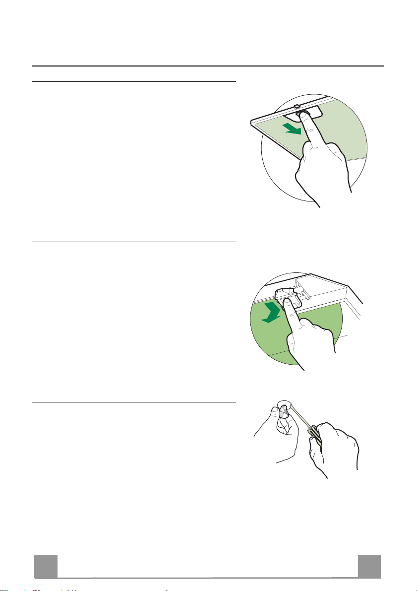
Removing the Grease Filters
Before carrying out Maintenance on the
EASY CLEANING Suction Unit:
• Disconnect the hood by switching off the
twopole switch on the mains power supply
line, or by switching off the main power
switch.
• Remove the grease filters from the hood.
• If the hood is of the recirculation ty pe, remove the odour filters:
• For hoods with a flat cartridge (A): turn the
fastening elements provided;
• For hoods with a bayonet cartridge (B):
turn as indicated and extract.
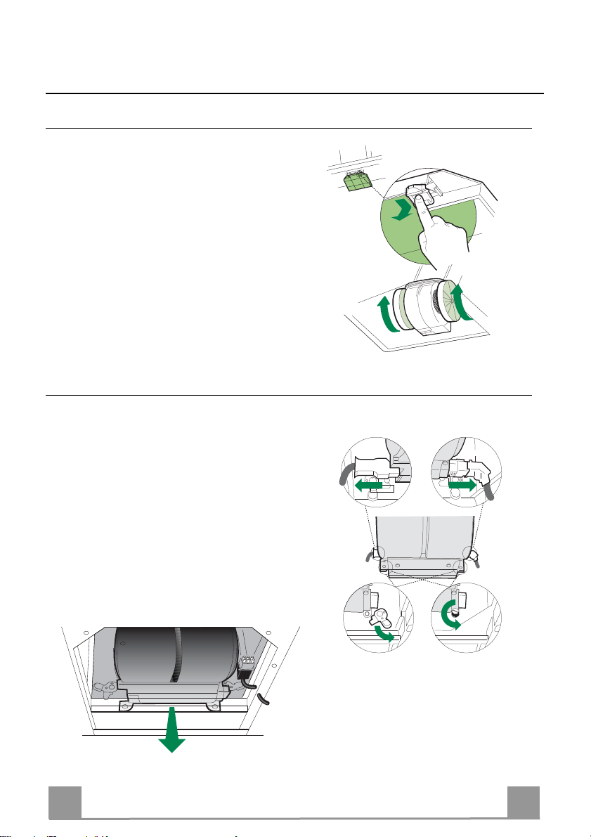
Disconnecting the EASY CLEANING Suction Unit
• Disconnect the power connector Ca and the
control and lighting connector Cmd on the
sides of the unit.
• For wall-mounted hoods and free-standing
hoods with square chimney, turn the levers
Lb locking the suction unit, so that they
disconnect from the pins.
• For free-standing hoods with round chimney, unscrew the plugs Vb locking the suction unit.
• Pull the suction unit forwards so that it unhooks from the support pins, and remove it
downwards through the air outlet.
A
B
CmdCa
Lb
Vb
EN
1
11
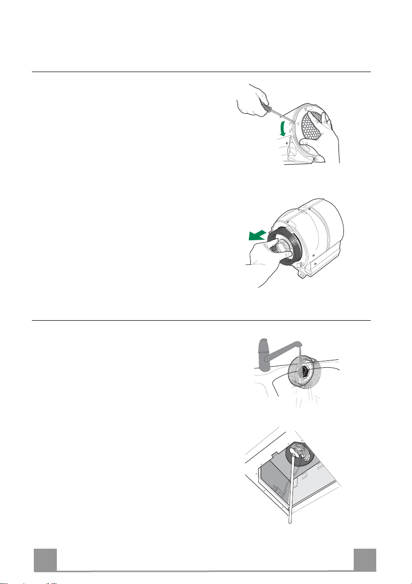
Dismantling Washable Parts
• To remove the side grilles protecting the
fans, lift up the stop tooth using a knife or
screwdriver and turn the grilles in the direction indicated by the arrow.
• Grasp the fans in the holes provided and
pull to extract.
CLEANING
O
LOCK
P
E
N
FREE
• Wash the fans and the protection grilles,
using normal washing-up liquid. These
elements can also be washed in the dishwasher.
• Using a damp cloth and a suitable detergent, clean the body of the suction device,
taking great care not to allow any water to
leak into the inside of the unit or into the
connector housings.
• Leave until completely dry bifore reassembling.
• Using a brush, clean the air outlet pipe as
far as you can reach.
EN
1
12

REASSEMBLY
N.B. To avoid reassembling the wrong way
round, the two fans have different couplings.
• Reassemble the fans on the corresponding
pins, pressing them until they snap into
place.
• Fit the protection grilles so that the teeth
coincide in the “FREE” position and when
turned to “LOCK”.
• Replace the EASY CLEANING suction
unit on the hood, inserting it in position and
connecting it to the support pins.
• Turn the lock levers, or screw in the lock
plugs.
• Connect the power connector and the
command connector to the sockets on the
sides of the suction device.
• Replace any activated charcoal odour filters.
• Replace the grease filters.
• Connect the hood to the power supply system, by turning the two-pole switch on the
mains power line to on, or by turning the
main switch on.
• Check that the hood is working properly,
by turning the motor and lighting on.
LOCK
O
P
E
N
FREE
EN
1
13

REKOMMENDATIONER OCH TIPS
Denna bruksanvisning är förutsedd för flera versioner av apparaten.
Det är möjligt att vissa enskilda utrustningsdetaljer, inte berör din apparat.
INSTALLATION
• Tillverkaren åtar s ig inget ansvar fö r fel som beror på felaktig eller olämplig installation.
• Minsta tillåtna avstånd mellan spishäll och köksfläk t är 650 mm (vissa modeller
kan installeras på en lägre höjd, se avsnitten mått och installation).
• Kontrollera att matn ingsnätets spänning motsvarar den som anges på märkskylten inuti köksfläkten.
• För Klass I-apparater, kontrollera att matningsnätet ger effektiv jordning.
• Anslut fläkten till frånluftkanalen via ett rör med e n diameter på minst 120 mm.
Anslutningsröret skall hållas så kort som möjligt.
• Anslut inte köksfläkte n till frånluf tkanaler som leder förb ränningsgaser (från pannor, eldstäder etc.).
• Om fläkten används tillsammans med icke-elektriska spisar (t.ex. gasspisar) måste tillräcklig ventilation garanteras i lokalen för att förhind ra backflöde av förbränningsgaser. Köket måste ha ett tilluftdon med direkt anslutning mot ytterluft för att
garantera inflöde av friskluft.
ANVÄNDNING
• Köksfläkten är uteslutande avsedd för hemanvändning, för att eliminera köksos.
• Använd aldrig köksfläkten för andra ändamål än det avsedda.
• Undvik höga flammor under köksfläkten medan fläkten är i drift.
• Justera gaslåg an så att flammorna endast berör kokkärlets undersida och inte
tränger upp längs dess sidor.
• Fritöser mås te övervakas kontinuerligt under användning: Överhettad olja kan
fatta eld.
• Köksfläkten skall inte användas av barn elle r personer som inte är insatta i ko rrekt användning.
• Apparaten är inte avsedd att användas av barn eller handikappade personer utan
övervakning.
• Tillaga inga flamberade maträtter under köksfläkten, då det finns risk för eldsvåda
• Denna apparat får inte användas av personer (inklusiv e barn) med nedsatta fysiska, sensoriska eller mentala förmågor, eller av personer utan erfarenhet och
kunskap, om inte de är kontrollerade eller instruerade om användningen av apparaten av personer ansvariga för deras säkerhet.
• Barn ska övervakas för at t säk erst äll a att de int e lek er med a pparat en.
UNDERHÅLL
• Stäng av apparaten eller skilj den från matningsnätet innan något underhållsarbete utförs.
• Rengör och/eller byt filtren med angivet intervall (Risk för eldsvåda).
• Rengör köksfläkten med en fuktig trasa och neutralt flytande diskmedel.
Symbolen på produkten eller emballag et a nger at t produ kten i nte få r hante ras som h ushål lsavfall. Den skall i stället lämnas in på uppsamlingsplats för återvinning av el- och elektronikkomponenter. Genom att säkerställa att produkten hanteras på rätt sätt bidrar du till att förebygga eventuellt
negativa miljö- och hälsoeffekter som kan uppstå om produkten kasseras som vanligt avfall. För
ytterligare upplysningar om återvi nning bör du k ontakta lok ala myndighete r eller soph ämtningstjän st
eller affären där du köpte varan.
SE
1
14
1
2.1
2.2
2
12c
12a
7.2.1 11
11
12a
9
7.3
10
14.1
15
EGENSKAPER
Komponenter
Ref. Antal Produktkomponenter
1 1 Köksfläkthus, komplett med: manöveranordningar, lampa, fläkt,
2 1 Teleskopisk skorsten bestående av:
2.1 1 Överdel
2.2 1 Underdel
9 1 Reduktionsfläns ø 150-120 mm
10 1 Fläns ø 150 med backventil
14.1 2 Anslutningsstycke för luftutsläpp
15 1 Luftutsläppsgrenrör
Ref. Antal Installationskomponenter
7.3 1 Luftutsläppsgrenrörs konsol
7.2.1 2 Fästvinklar för övre skorstensdel
11 6 Väggpluggar
12a 6 Skruvar 4,2 x 44,4
12c 6 Skruvar 2,9 x 9,5
1 Dokumentation
filter
SE
1
15
Mått
SE
Min.
650mm
Min.
650mm
1
16
INSTALLATION
Borrning i vägg och montering av fästen
1÷2
7.3
7.2.1
11
12a
650 min.
116
116
X
535
Markering på vägg:
• Ett vertikalt streck upp till taket eller max. gränsen, i mitten av köksfläktens monteringsområde.
• Ett horisontellt streck 650 mm ovanför tillagningshällen.
• Placera konsolen 7.2.1 1-2 mm från taket eller den övre gränsen enligt anvisningarna. Ställ in konsolens
mitt (hack) på det vertikala referensstrecket.
• Markera konsolens hål.
• Placera konsolen 7.2.1 X mm under den första konsolen (X = höjd för medföljande övre skorsten) enligt
anvisningarna.Ställ in konsolens mitt(hack)på det vertikala referensstrecket.
• Markera konsolens hål.
• Markera en referenspunkt 116 mm från det vertikala referensstrecket och 535 mm ovanför det horisontella referensstrecket enligt anvisningarna.
• Upprepa detta moment på den motsatta sidan.
• Borra 8 mm hål i de markerade punkterna.
• Sätt in expansionspluggarna 11 i hålen.
• Fäst den nedre konsolen 7.2.1 med de medföljande skruvarna 12a (4,2 x 44,4).
• Sätt ihop den övre konsolen 7.2.1 och stödkonsolen 7.3 med de medföljande två skruvarna 12a (4,2 x
44,4).
• Skruva fast de två medföljande skruvarna 12a (4,2 x 44,4) i hålen för fastsättning av köksfläktsstommen.Se till att lämna ett utrymme på 5-6 mm m ellan väggen och skruvhuvudet.
SE
1
17
12a
Vr
9
ø 120ø 150
10
10
ø 150
15
14.1
7.3
Montering av köksfläktsstomme
• Innan du hakar fast köksfläktsstommen, skruva fast de 2 skruvarna Vr som sitter i upphängningspunkterna på köksfläktsstommen.
• Haka fast köksfläktsstommen i de förberedda 12a skruvarna.
• Skruva fast 12a stödskruvarna.
• Skruva på skruvarna Vr för att nivellera köksfläktsstommen.
Anslutningar
LUFTUTSLÄPP SUGANDE VERSION
För installation i sugande version anslut fläktkåpan till utgångsrörsystemet med ett styv eller böjlig slang med en diameter på
150 eller 120 mm, valet lämnas åt installatören.
Anslutning till slang med ø 150
• Sätt i flänsen ø 150 10 på utgången av köksfläktsstommen.
• Fäst slangen med lämpliga slangklämmor. Nödvändigt material
medföljer inte.
Anslutning till slang med ø 120
• För anslutning med en slang med 120 mm diameter, sätt i reduktionsflänsen 9 på den tidigare installerade ø 150 flänsen.
• Fäst slangen med lämpliga slangklämmor. Nödvändigt material
medföljer inte.
• I båda fallen avlägsna eventuella luktfilter med aktivt kol.
KOLFILTER
• För in förlängningsstyckena 14.1 i grenröret 15.
• Sätt i anslutningen 15 i stödkonsolen 7.3 och fäst den med en
skruv.
• Kontrollera att förlängningsstyckna sitter horisontelt och vertikalt uppriktade. Om så inte är fallet justera detta.
• Anslut grenröret 15 till köksfläkten genom att anvä’nda en fast
eller en flexibel slang.
• Montera dit kolfilter
SE
1
18
 Loading...