

Page 1
Istruzioni per l’uso e l’installazione
Instructions for use and installation
Mode d’emploi et installation
Bedienungsanleitung und Einrichtung
Kullan
ım ve montaj talimatları
GB
IT
FR
DE
TR
Cappa
Cooker Hood
Hotte de Cuisine
Dunstabzugshaube
Davlumbaz
FQD 907
Page 2

IT
Libretto di Istruzioni
INDICE
CONSIGLI E SUGGERIMENTI ..............................................................................................................................................7
CARATTERISTICHE..............................................................................................................................................................8
INSTALLAZIONE....................................................................................................................................................................9
USO......................................................................................................................................................................................12
MANUTENZIONE.................................................................................................................................................................13
2
2
Page 3

EN
Instructions Manual
INDEX
RECOMMENDATIONS AND SUGGESTIONS....................................................................................................................16
CHARACTERISTICS............................................................................................................................................................17
INSTALLATION ....................................................................................................................................................................18
USE.......................................................................................................................................................................................21
MAINTENANCE....................................................................................................................................................................22
3
3
Page 4

FR
Manuel d’Instructions
SOMMAIRE
CONSEILS ET SUGGESTIONS ..........................................................................................................................................25
CARACTERISTIQUES.........................................................................................................................................................26
INSTALLATION ....................................................................................................................................................................27
UTILISATION........................................................................................................................................................................30
ENTRETIEN..........................................................................................................................................................................31
4
4
Page 5

DE
Bedienungsanleitung
INHALTSVERZEICHNIS
EMPFEHLUNGEN UND HINWEISE....................................................................................................................................34
CHARAKTERISTIKEN..........................................................................................................................................................35
MONTAGE............................................................................................................................................................................36
BEDIENUNG.........................................................................................................................................................................39
WARTUNG............................................................................................................................................................................40
5
5
Page 6

TR
Kullanim Kilavuku
IÇERIKLER
TAVSIYELER VE ÖNERILER ..............................................................................................................................................43
ÖZELLIKLER........................................................................................................................................................................44
MONTAJ...............................................................................................................................................................................45
KULLANIM............................................................................................................................................................................48
BAKIM...................................................................................................................................................................................49
6
6
Page 7

IT
CONSIGLI E SUGGERIMENTI
650 mm min.
INSTALLAZIONE
• Il produttore declina qualsiasi responsabilità per danni dovuti ad installazione non corretta o non conforme alle regole dell’arte.
• Verificare che la tensione di rete c orrisponda a quella riportata nell a
targhetta posta all’interno della Cappa.
• Per Apparecchi in Classe I
stico garantisca un corretto scarico a terra.
• Collegare la Cappa all’uscita dell’aria aspirata con tubazione di diametro pari o superiore a 120 mm. Il p erc orso della tubazione deve essere il più breve possibile.
• Non collegare la Cappa a condotti di scarico dei fumi prodotti da
combustione (caldaie, caminetti, ecc.).
• Nel caso in cui nella stanza vengano utilizzati sia la Cappa che apparecchi non azionati da energia elettrica (ad esempio apparecchi utilizzatori di gas), si deve provvedere ad una aerazione sufficiente
dell’ambiente. Se la cucina ne fosse sprovvista, praticare un’apertura
che comunichi con l’esterno, per garantire il richiamo d’aria pulita.
USO
• La Cappa è stata progettata escl usivamente per uso domestico, per
abbattere gli odori della cucina.
• Non fare mai uso improprio della Cappa.
• Non lasciare fiamme libere a fo rte intensità sotto la Cappa in funzione.
• Regolare sempre le fiamme in mod o da evitare una evidente fuoriuscita laterale delle stesse rispetto al fondo delle pentole.
• Controllare le friggitrici durante l’ uso: l’olio surriscaldato potrebbe infiammarsi.
• La Cappa non deve essere utilizzata da bambini o persone non abilitate all’uso corretto.
MANUTENZIONE
• Pri ma di procedere a quals iasi opera zi one di manutenzione, di sins erire la Cappa togliendo la spina elettrica o spegn endo l’interruttore generale.
• Effettuare una scrupolosa e tempestiva manutenzione dei Filtri secondo gli intervalli consigliati.
• Per la pulizia delle superfici della Cappa è sufficiente utilizzare un
panno umido e detersivo liquido neutro.
a
accertarsi che l’impianto elettrico dome-
7
7
Page 8

IT
CARATTERISTICHE
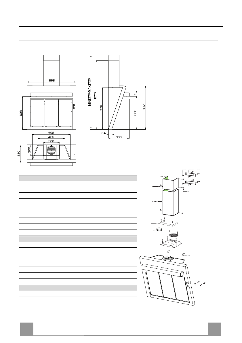
Ingombro
Componenti
Rif. Q.tà Componenti di Prodotto
1 1 Corpo Cappa completo di: Comandi, Luce, Gruppo
2.1 1 Camino Superiore
2.2 1 Camino Inferiore
8 1 Griglia direzionata Uscita Aria
9 1 Flangia
15 1 Angolare
16 1 Coperchio filtrante
Rif. Q.tà Componenti di Installazione
7.2.1 2 Staffe Fiss aggi o Camino Superiore
11 6 Tasselli
11a 2 Tasselli SB 12/10
12a 6 Viti 4,2 x 44,4
12c 10 Viti 2,9 x 6,5
12d 6 Viti 2,9 x 9,5
Q.tà Documentazione
1 Libretto Istruzioni
Ventilatore, Filtri
12a
7.2.1 11
2.1
2.2
15
9
8
16
12c
12d
12d
12c
11a
1
11
12a
8
8
Page 9
IT
INSTALLAZIONE
una linea Verticale fino al soffitto o al limite superiore, al centro della zona prevista per il
e-
i-
e-
a X mm sotto la prima staffa (X = altezza Camino
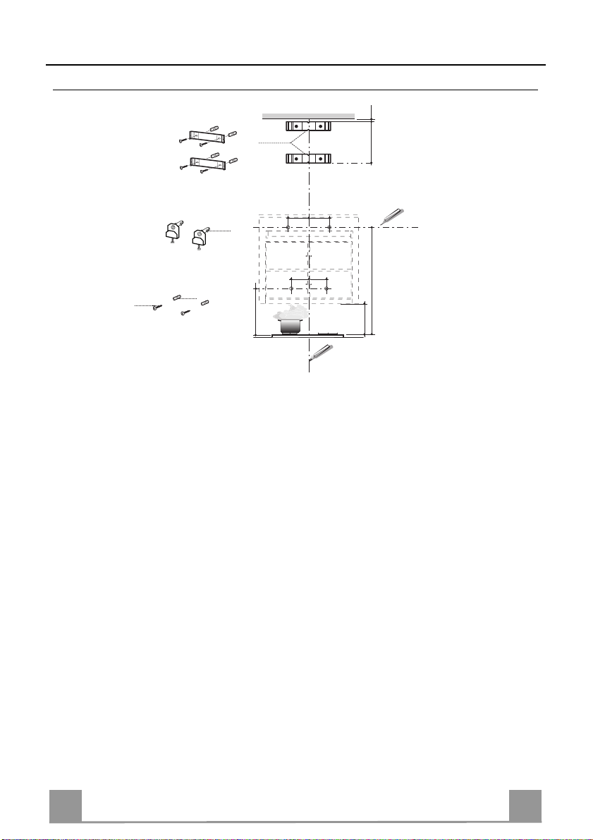
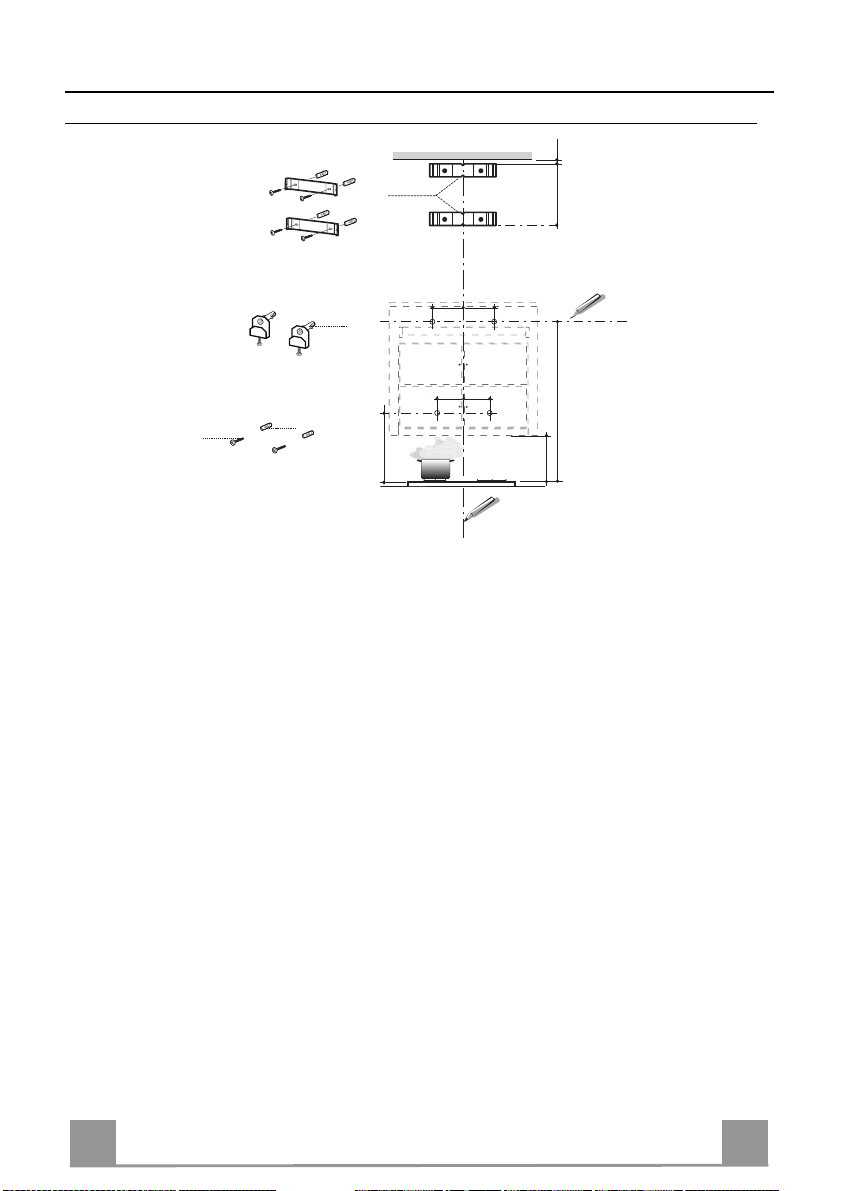
Foratura Parete e Fissaggio Staffe
1÷2
7.2.1
X
200 200
11
180
22
362
180
960
250
12a
11a
11
Tracciare sulla Parete:
•
montaggio della Cappa;
• una linea Orizzontale a 960 mm min. sopra il Piano di Cottura.
• Segnare un punto (1) sulla linea orizzontale a 200 mm alla destra della linea verticale di rif
rimento.
• Ripetere questa operazione dalla parte opposta, verificandone il livellamento.
• Segnare come indicato, un punto di riferimento (2) a 180 mm dalla linea Verticale di rifer
mento, e 362 mm sopra il Piano di Cottura.
• Ripetere questa operazione dalla parte opposta, verificandone il livellamento.
• Forare ø 12 mm i punti (1) segnati.
• Forare ø 8 mm i punti (2) segnati.
• Inserire i tasselli con staffa 11a nei fori 1 e avvitare.
• Inserire il tassello 11 nel foro 2.
• Appoggiare come indicato la Staffa 7.2.1 a 1-2 mm dal soffitto o dal limite superiore, allin
ando il suo centro (intagli) sulla linea Verticale di riferimento.
• Segnare i centri dei Fori della Staffa.
• Appoggiare come indicato la S taffa 7.2.1
Superiore in dotazione), allineando il suo centro (intagli) sulla linea Verticale di riferimento.
• Segnare i centri dei Fori della Staffa.
• Forare ø 8 mm i punti segnati.
• Inserire i tasselli 11 nei fori.
• Fissare le Staffe, utilizzando le Viti 12a (4,2 x 44,4) in dotazione.
9
9
Page 10
IT 110
Montaggio Corpo Cappa
• Aprire i pannelli aspiranti.
• Sganciare il pannello dal corpo cappa facendo scorre-
re l’apposita leva del perno di fissaggio.(A)
• Togliere i Filtri Antigrasso agendo sulle apposite
maniglie.
• Regolare le due viti Vr, delle staffe 11a, ad inizio
corsa.(B)
• Agganciare il corpo cappa alle 2 staffe 11a.
• Dall’interno del corpo cappa agire sulle Viti Vr per
livellare il Corpo Cappa.
• Avvitare la vite di sicu rezza 11.
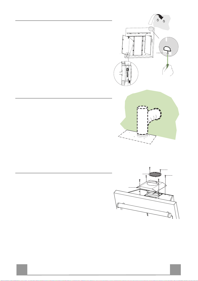
Connessioni
USCITA ARIA VERSIONE ASPIRANTE
Per installazione in Versione Aspirante collegare la
Cappa alla tubazione di uscita per mezzo di un tubo
rigido o flessibile di ø150 la cui scelta è lasciata all'installatore.
• Fissare il tubo con adeguate fascette stringitubo. Il
materiale occorrente non è i n dotazione.
• Togliere eventuali Filtri Antiodore al Carbone attivo.
Vr
(B)
(A)
ø 150
Uscita aria Versione Filtrante
8
12d
12c
Per installazione in Versione Fi ltrante è necessario acquistare il kit opzionale Cartuccia al carbone attivo.
16
• Avvitare il coperchio filtrante sull’uscita aria, utilizzando quattro viti 12c (2,9 x 6,5).
• Fissare la Griglia direzionata 8 sull’uscita dell’aria
riciclata con 2 Viti 12d (2,9 x 9,5) in dotazione.
Page 11

IT 111
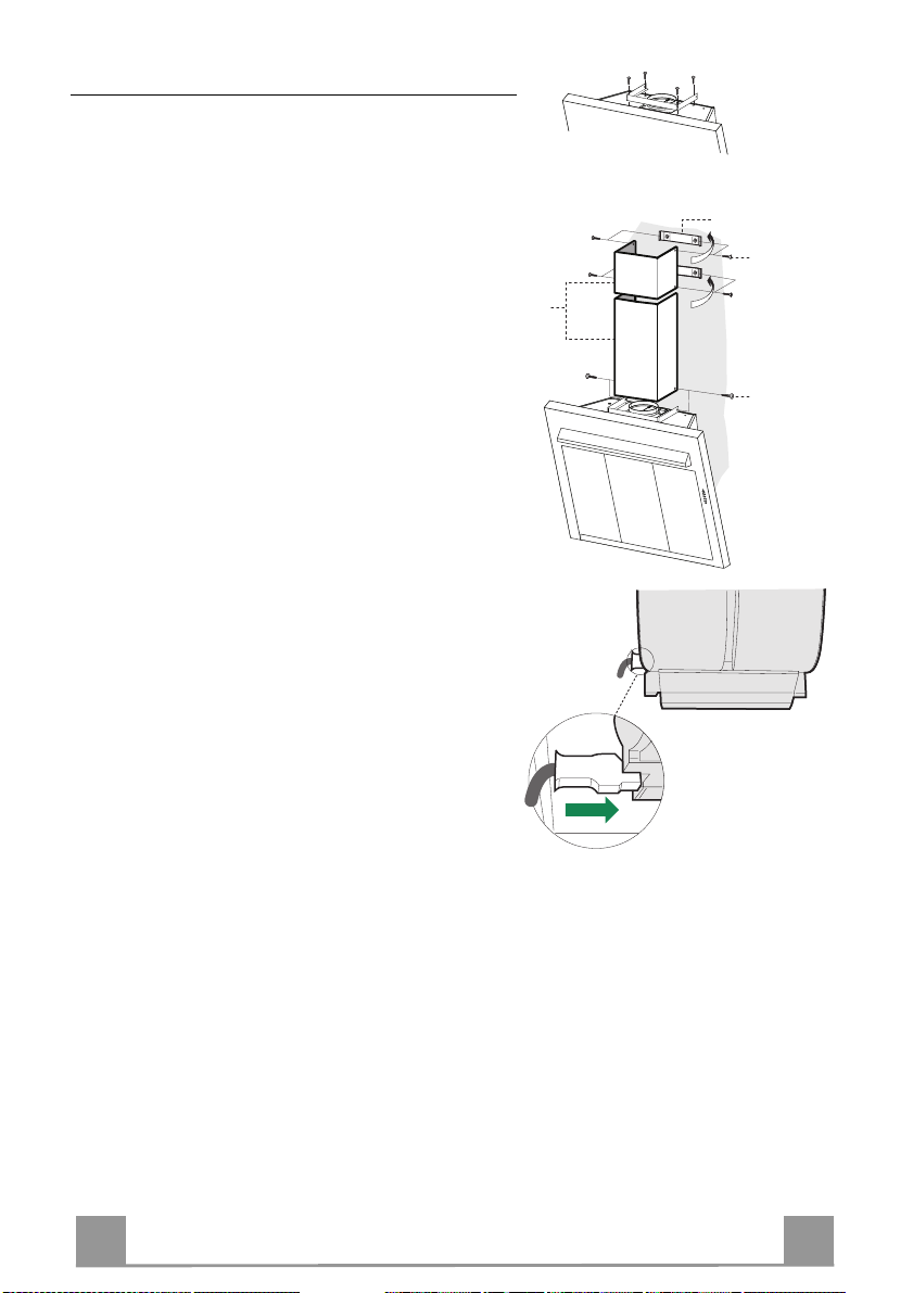
Montaggio Camino
Il camino può essere installato solo con la cappa collegata in versione aspirante.
• Fissare l’angolare 15 al corpo cappa con le viti 12d
(2,9 x 9,5) in dotazione.
Camino superiore
• Allargare leggermente le due falde laterali, agganciarle dietro le Staffe 7.2.1 e richiuderle fino a battuta.
• Fissare lateralmente alle Staffe con 4 Viti 12c (2,9 x
6,5) in dotazione.
Camino inferiore
• Allargare leggermente le due falde laterali del Camino, agganciarle tra il Camino superiore e la parete e
richiuderle fino a battuta.
• Fissare lateralmente la parte inferiore al Corpo Cappa, con 2 Viti 12c (2,9 x 6,5) in dotazione.
CONNESSIONE ELETTRICA
• Collegare la Cappa all’Alimentazione di Rete interponendo un Interruttore bipolare con apertura dei
contatti di almeno 3 mm.
• Rimuovere i Filtri antigrasso (vedi par. “Manutenzione”) e assicurarsi che il connettore del Cavo di alimentazione sia correttamente inserito nella presa
dell’Aspiratore
7.2.1
12c
2.1
2
2.2
12c
Page 12
IT 112
USO
A
B
D
C
E
GH
F
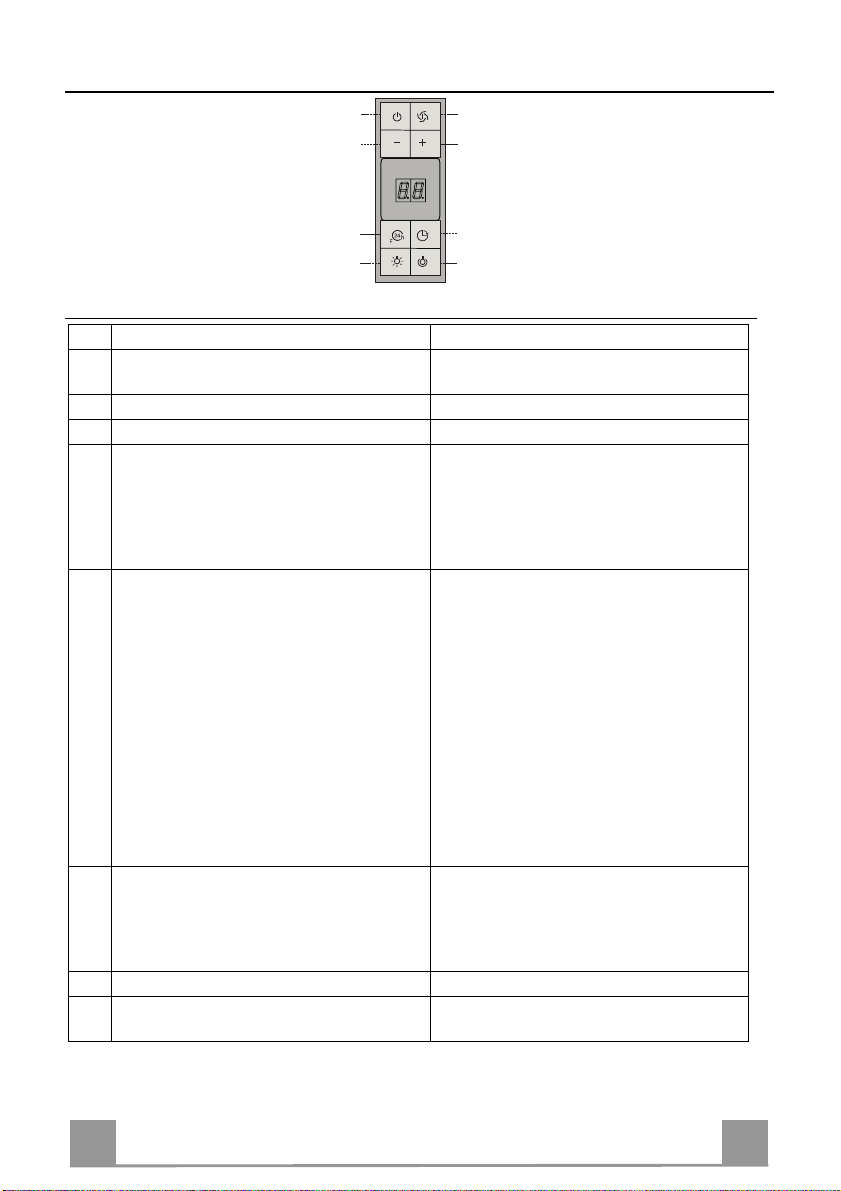
Quadro comandi
Tasto Funzione Display
Accende e spegne il motore di aspirazione
A
all’ultima velocità utilizzata.
B Decrementa la velocità di esercizi o.
C Incrementa la velocità di esercizio.
Attiva la velocità intensiva da qualsiasi velo-
D
cità anche da motore spento, tale velocità è
temporizzata a 10 minuti, al termine del tempo
il sistema rit orna a lla veloci tà prec edentemen te
impostata. Adatta a fronteggiare le massime
emissioni di fumi di cottura.
Attiva il motore ad una velocità che consente
E
un’aspirazione di 100 m
3
/h per 10 minuti ogni
ora, terminati il motore si ferma.
Con l’allarme filtri i n corso premendo il tasto
per circa 3 secondi si effettua il reset dell’allarme. Tali segnalazioni sono visibili solo a
motore spento.
Attiva lo spegnimento automatico ritardato di
F
30’. Adatto per completare l’eliminazione di
odori residui. Attivabile da qualsiasi posizione,
si disattiva pre m e ndo il tasto o spegne ndo il
motore.
G Accende e spegne l’impianto di illuminazione.
Accende e spegne l’impianto di illumi nazione
H
ad intensità rido tt a.
Visualizza la velocità impostata
Visualizza HI e il punto in basso a dest ra lampeggia una volta al secondo.
Visualizza 24 e il punto in basso a destra lampeggia, mentre il motore è in funzione
Terminata la procedura si spegne la segnalazione precedentemente visualizzata:
FF segnala la necessità di lavare i filtri anti-
grasso metallici. L’allarme entra in funzione dopo 100 ore di lavoro effettivo
della Cappa.
EF segnala la necessità di sostituire i filtri al
carbone att ivo e devono anc he essere lavati i filtri antigrasso metallici. L’allarme
entra in funzione dopo 200 ore di lavoro
effettivo della Cappa.
Visualizza alternativamente la velocità di esercizio e il tempo rimanente allo spegnimento
della cappa. Il punto in basso a destra lampeggia.
Page 13
IT 113
MANUTENZIONE
TELECOMANDO (OPZIONALE)
Questo apparecchio può essere c omandato per mezzo di un tel ecomando, alimentato con pile alcaline zinco-carbone da 1,5 V del
tipo standard LR03-AAA.
• Non riporre il telecomando in prossimità di fonti di calore.
• Non disperdere le pile nell’ambiente, depositarle negli appositi
contenitori.
Filtri antigrasso metallici
Sono lavabili anche in lavastoviglie, e necessitano di essere lavati
quando sul display appare FF o almeno ogni 2 mesi circa di utilizzo o più frequentemente, per un uso particolarmente intenso.
Reset del segnale di allarme
• Spegnere le Luci e il Motore di aspirazione, quindi qualora
fosse attivata la funzione 24h disattivarla.
• Premere il tasto E sino allo spegnersi del display.
Pulizia Filtri
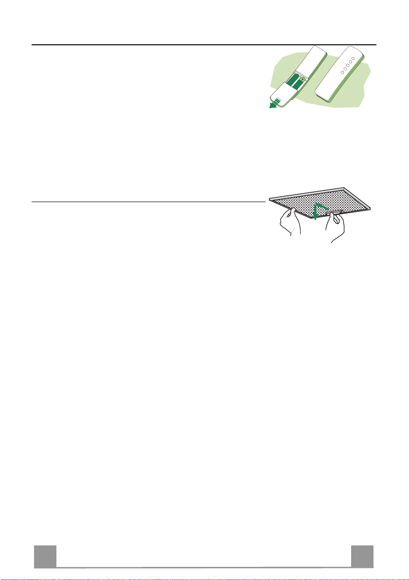
• Aprire i Comfort Panel tirandoli.
• Togliere i Filtri uno alla volta, spingendoli verso la parte posteriore del gruppo e tir ando contemporaneamente verso il basso.
• Lavare i Filtri evitando di piegarli, e lasciarli asciugare prima
di rimontarli. (Un’event uale cambiamento del colore dell a superficie del filtro, che potrebbe verificarsi nel tempo, non pregiudica assolutamente l’efficienza dello stesso.)
• Rimontarli facendo attenzione a mantenere la maniglia verso la
parte visibile esterna.
• Richiudere i comfort panel.
Page 14
IT 114
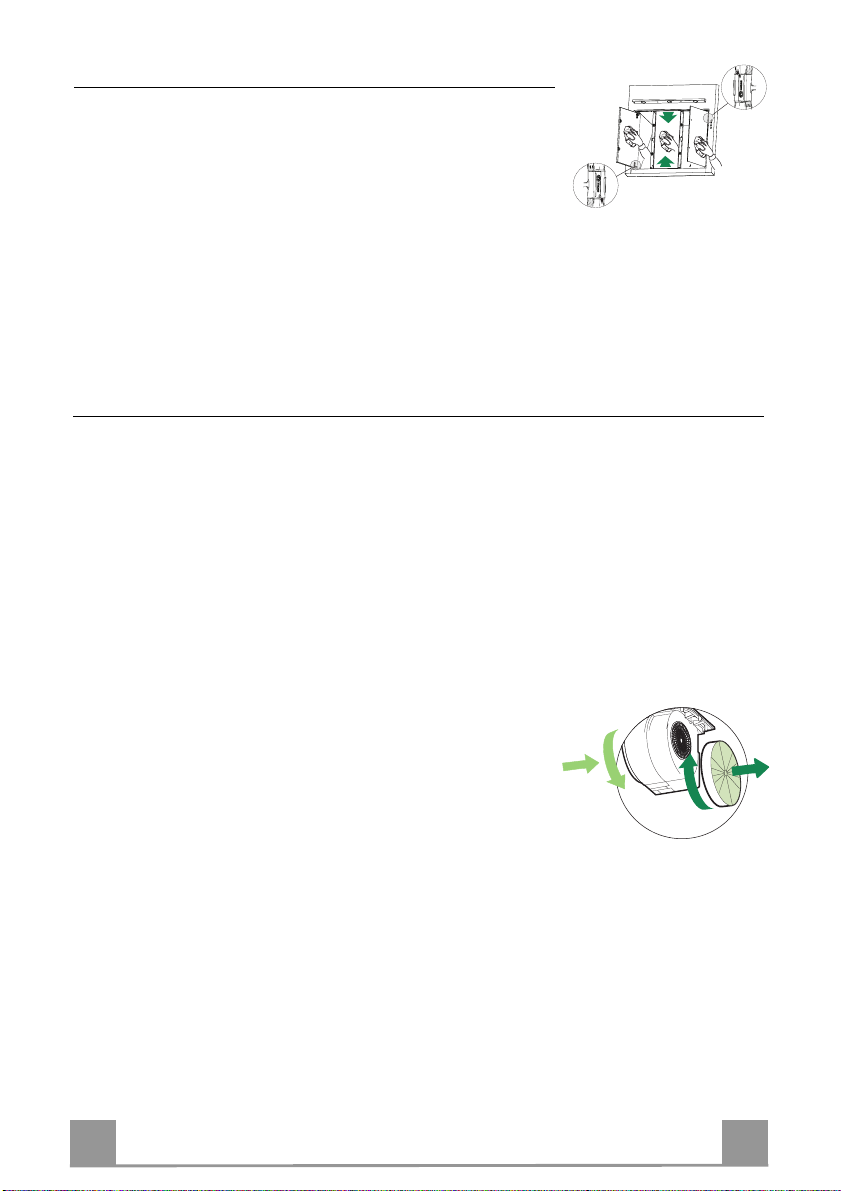
Pannelli Aspiranti
A
B
• Aprire i pannelli aspiranti.
• Sganciare i pannelli laterali dal corp o cappa facendo scorrere
l’apposita leva del perno di fissaggio.
• Sganciare il pannello Centrale tirandolo energicamente, con
entrambe le mani.
• Pulire esternamente con un panno umido e detersivo liquido
neutro.
• Pulirlo anche intern amente utilizzando un panno umido e detergente neutro; non utilizzare panni o spugne bagnate, né getti
d’acqua; non utilizzare sost anze abrasive.
Filtri antiodore al Carbone attivo (Versione Filtrante)
• Non è lavabile e non è rigenerabile, va sostituito quando sul display appare EF o almeno
ogni 4 mesi.
Attivazione del segnale di allarme
• Nelle Cappe in Versione Filtrante, la segnalazione di Allarme saturazione Filtri va attivata al
momento dell’installazione o successivamente.
• Spegnere le Luci e il Motore di aspirazione.
• Scollegare la cappa dall’alimentazione di rete.
• Ripristinare il collegamento tenendo premuto il tasto B.
• Rilasciando il tasto sul display compaiono due rettangoli in rotazione.
• Entro 3 secondi premere il Tasto B sino alla conferma che appare sul display:
• 2 lampeggi scritta EF - Allarme saturazione Filtro Carbone attivo ATTIVATO
• 1 lampeggio scritta EF - Allarme saturazione Filtro al Carbone attivo DISATTIVATO.
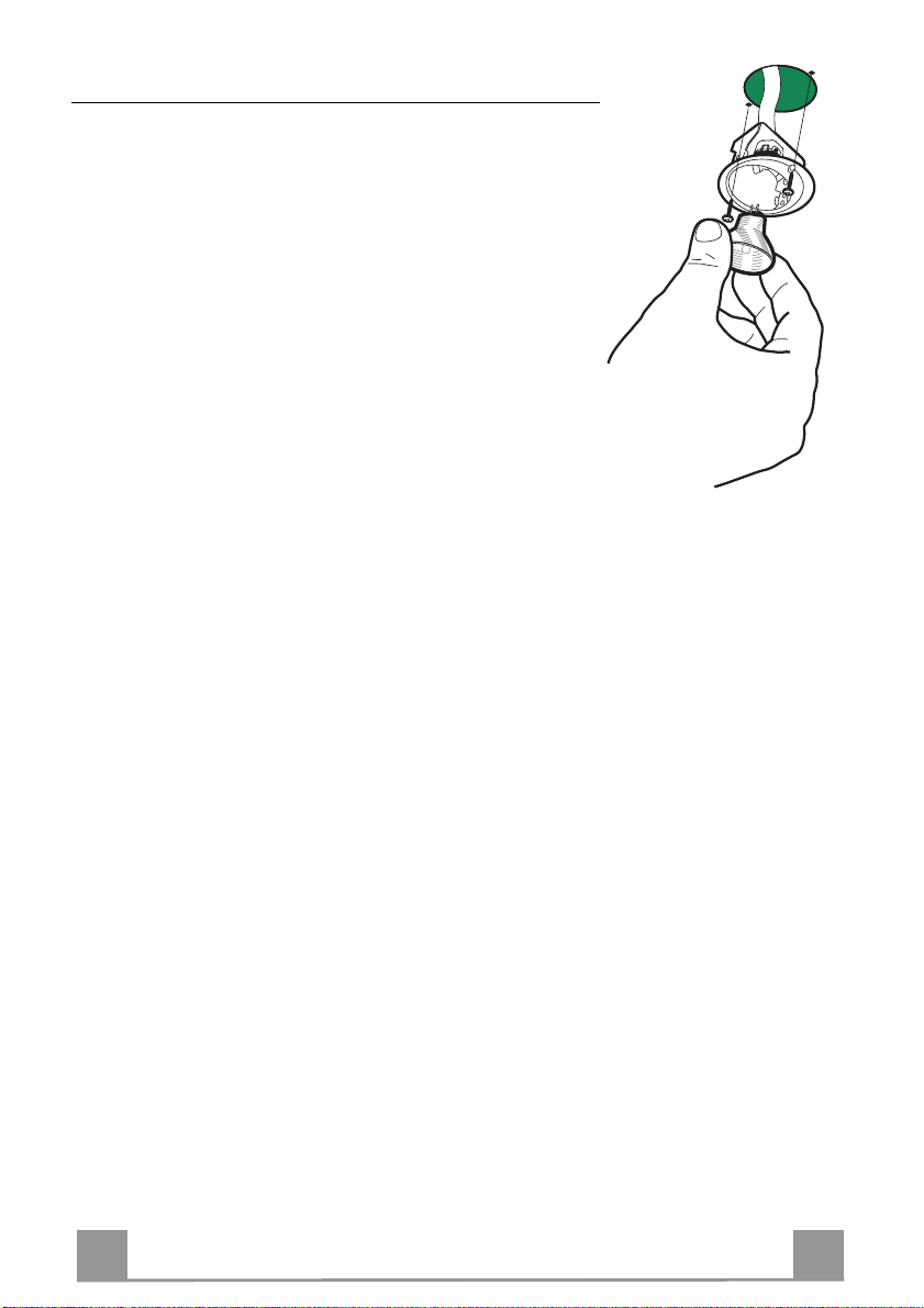
SOSTITUZIONE FILTRO ANTIODORE AL CARBONE ATTIVO
Reset del segnale di allarme
• Spegnere le Luci e il Motore di aspirazione, quindi qualora
fosse attivata la funzione 24h disattivarla.
• Premere il tasto E sino allo spegnersi del display.
Sostituzione Filtro
• Aprire i Comfort Panel tirandoli.
• Togliere i Filtri antigrasso metallici.
• Rimuovere il Filtro antiodore al Carbone attivo saturo, agendo
sugli appositi agganci.
• Montare il nuovo Filtro agganciandolo nella sua sede.
• Rimontare i Filtri antigrasso metallici.
• Richiudere i Comfort Panel.
Page 15
IT 115
Illuminazione
SOSTITUZIONE LAMPADE
Lampade alogene da 20 W.
• Togliere le due viti che fissano il Supporto illuminazione e sfilarlo dalla Cappa.
• Estrarre la Lampada dal Supporto.
• Sostituirla con una nuova di uguali caratteristiche, facendo attenzione di inserire correttamente i due spinotti nella sede del
Supporto.
• Rimontare il Supporto fissandola con le due Viti precedentemente tolte.
Page 16
EN 116
RECOMMENDATIONS AND SUGGESTIONS
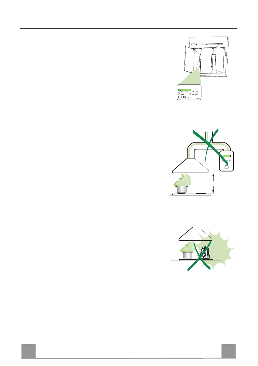
650 mm min.
INSTALLATION
• The manufacturer will not be held liable for any damages resulting
from incorrect or improper installation.
• Check that the mains voltage corresponds to that indicated on the
rating plate fixed to the inside of the hood.
• For Class I appliances, check t hat th e domesti c po wer s upply gua ran tees adequate earthing.
Connect the extractor t o the exhaust flue thro ugh a pipe of minimum
diameter 120 mm. The route of the flue must be as short as possible.
• Do not connec t the extractor ho od to exhaust ducts carrying comb ustion fumes (boilers, fireplaces, etc.).
• If the extractor is used in conjunction with non-el ectrical appliances
(e.g. gas burning appliances), a suffici ent degree of aeration must be
guaranteed in the room in order to prevent the backflow of exhaust
gas. The kitchen must have an opening communicating directl y with
the open air in order to guarantee the entry of clean air.
USE
• The extractor hood has been designed exclusi vely for domes tic use to
eliminate kitchen smells.
• Never use the hood f or purposes ot her than for which it h as ben designed.
• Never leave high naked flames under the hood when it is in operation.
• Adjust the flame intensity to di rect it onto the bottom of the pan only,
making sure that it does not engulf the sides.
• Deep fat fryers must be continuously monitored during use: overheated oil can burst into flames.
• The hood sh ould not be used by chil dren or persons not ins tructed in
its correct use.
MAINTENANCE
• Switch off or unplug the appliance from the mains supply before carrying out any maintenance work.
• Clean and/or replace the Filters after the specified time period.
• Clean the hood using a damp cloth and a neutral liquid detergent.
Page 17

EN 117
CHARACTERISTICS
Hood Body, complete with: Controls, Light, Blower,
Components
Ref. Q.ty Product Components
1 1
Filters
2.1 1 Upper Section
2.2 1 Lower Section
8 1 Directional Air Outlet grille
9 1 Flange
15 1 Angle iron
16 1 Filter cover
Ref. Q.ty Installation Components
7.2.1 2 Upper Chimney Section Fixing Brackets
11 6 Wall Plugs
11a 2 Wall Plugs SB 12/10
12a 6 Screws 4,2 x 44,4
12c 10 Screws 2,9 x 6,5
12d 6 Screws 2,9 x 9, 5
Q.ty Documentation
1 Instruction Manual
Dimensions
12a
7.2.1 11
2.1
2.2
15
9
8
16
12c
12d
12d
12c
11a
1
11
12a
Page 18

EN 118
INSTALLATION
Wall drilling and bracket fixing
7.2.1
1÷2
X
11a
200 200
11
180
12a
11
180
22
362
960
250
On the wall, draw
• a Vertical line up to the ceiling or upper limit, at the centre of the area in which the Hood is
to be fitted;
• a Horizontal line at a minimum of 960 mm above the Cooker Top.
• Mark a point (1) on the horizontal line, 200 mm to the right of the vertical reference line.
• Repeat this operation on the other side, checking that the two marks are level.
• Mark a reference point (2) as indicated at 18 0 mm from the vertical reference l ine and 362
mm above the Cooker Top.
• Repeat this operation on the other side, checking that the two marks are level.
• Drill at the points (1) marked, using a ø 12 mm drill bit.
• Drill at the points (2) marked, using a ø 8 mm drill bit.
• Insert the bracket plugs 11a into the holes 1 and screw into place.
• Insert plug 11 into hole 2.
• Place bracket 7.2.1 on the wall as shown about 1-2 mm from the ceiling or upper limit align-
ing the centre (notch) with the vertical reference line.
• Mark the wall at the centres of the holes in the bracket.
• P l ace br acket 7.2.1 on the wall as shown at X mm below the first bracket (X = height of the
upper chimney section supplied), aligning the centre (notch) with the vertical line.
• Mark the wall at the centres of the ho les in the bracket.
• Drill ø 8 mm holes at all the centre points marked.
• Insert the wall plugs 11 in the holes.
• Fix the brackets using th e 12a screws (4,2 x 44,4) supplied.
Page 19

EN 119
Mounting the hood body
• Open the ducting panels.
• Disconnect the panel from the hood canopy by sliding the fixing p in lever.(A)
• Remove the metal grease filters by turning the handles provided.
• Adjust the two screws Vr, on brackets 11a, to a mini-
mum.(B)
• Hook the hood canopy onto the two brackets 11a.
• From inside the hood canop y, adjust the screws Vr to
set the Hood Canopy level.
• Tighten the safety screw 11.
Connections
DUCTED VERSION AIR EXHAUST SYSTEM
When installing the ducted version, connect th e hood to
the chimney using either a flexible or rigid
pipe ø 150 mm, the choice of which is left to the installer.
• Fix the pipe in position using sufficient pipe
clamps (not supplied).
• Remove any activated charco al filters.
Vr
(B)
(A)
ø 150
RECIRCULATION VERSION AI R OUTLET
8
12d
12c
To install the Recirculation Version of the hood, the
optional Activated charco al cartridge kit must be purchased.
16
• Screw the filter cover onto the air outlet, using four
screws 12c (2.9 x 12.5).
• Fix the directional grille 8 on the recirculation air
outlet using the 2 screws 12d (2,9 x 9,5) provided.
Page 20

EN 220
Flue assembly
The chimney can only be installed with exhausting
hood
• Fasten the angle iron 15 to the hood can op y usin g th e
screws 12d (2,9 x 9,5) provided.
Upper exhaust flue
• Slightly widen the two sides of the upper flue and
hook them behind the brackets 7.2.1, making sure
that they are well seated.
• Secure the sides to the brackets using the 4 screws
12c (2,9 x 6,5) supplied.
Lower ex haust flue
• Slightly widen the two sides of the flue and hook
them between the upper flue and the wall, making
sure that they are well seated.
• Fix the lower part laterally to the hood body using
the 2 screws 12c (2,9 x 6,5) supplied.
ELECTRICAL CONNECTION
• Connect the hood to the mains through a two-pole
switch having a contact gap of at least 3 mm.
• Remove the grease filters (see paragraph Maintenance) being sure that the connector of the feeding
cable is correctly inserted in the socket p laced on t he
side of the fan.
7.2.1
12c
2.1
2
2.2
12c
Page 21

EN 221
USE
By pressing this key it is possible to activate
selected speed. This function is suitable for
A
B
D
C
E
GH
F
Control board
Key Function Display
Switches the ext ractor motor on and off at the
A
latest selected speed
Decreases the suction speed.
B
Increases the suction speed.
C
D
the intensive speed from any previously selected speed . The intensiv e speed can be acti vated even when th e motor is O FF. Th is speed
has been timed at 10 minutes. After that time
the system activates automatically the latest
cooking conditions when vapours and smells
are of the utmost emission.
By pressing this key it is possible to set up the
E
motor to a suction speed at 100 m
3
minutes every hour. After this the motor
switches off automatically.
When the filter saturation is going on it is possible to reset the alarm by pressing this key for
about 3 seconds. The indication i s visible only
when the motor is off.
By pressing this key it is possible to set the
F
delayed shutdown of the appliance to 30 minutes. This function is suitable for a complete
elimination of the residual smells. It can be
activated at any position, and it is deactivated
by pressing the key again or by switching off
the motor.
Turns light on and off .
G
Turns light on and off a t reduced intensity.
H
/h lasting 10
Indicates the selected speed.
HI appears. The sp ot down on the right side
flashes once a second.
Indicates the 24-function. The spot down on
the right side flashes and the motor is on.
Once the process is finished the previous indication disappear s :
FF Indicates that the metal grease filters
saturation a larm has been t riggered, and
the filters need to be washed. Th e alarm
is triggered after 100 working hours.
EF Indicates that the charcoal filter satura-
tion alarm has been triggered, and the filter has to be replaced; the metal grease
filters must also be washed. The charcoal
filter is triggered after 200 working hours.
Indicates alternately the selected speed of the
hood and the tim e left before the hood shutdown. The sp ot down on the right side flashes.
Page 22

EN 222
MAINTENANCE
REMOTE CONTROL (OPTIONAL)
The appliance can be controlled using a remote control powered
by a 1.5 V carbon-zinc alkaline batteries of the standard LR03AAA type.
• Do not place the remote con t rol near to heat sources.
• Used batteries must be disposed of in the proper manner.
Metal grease filters
Filters can be washed in the dish machine. They need to be
washed when FF-sign appears on the display or in any case every
2 months, or even more frequently in case of particularly intensive use of the hood.
Alarm reset
• Switch off the hood and the lights. If the 24h-function has been
activated this has to be deactivated.
• Press the E-key till the display is unlit.
Cleaning the filters
• Pull the comfort panels to open them.
• Remove the filters one by one pushing them towards the back
side of the hood unit and simultaneously pulling downwards.
• Any kind of bending of the filters has to be avoided when
washing them. Before fitting them again into the hood make
sure that they are completely dry. (The colour of the filter surface may change throughout the time but this has no influence
to the filter efficiency).
• When fitting the filters into the hood pay attention that they are
mounted in correct position the handle facing outwards.
• Close the comfort panel.
Page 23

EN 223
Comfort panels
A
B
• Open the comfort panels.
• To unfasten the side panels from the hood casing it is necessary to slide the fixing pivot lever.
• When unfastening the central comfort panel pull it forcefully
using both hands.
• It is recommended to use a neutral detergent liquid and a damp
cloth when washing the outer surface of the comfort panel.
• Wash the inner part of the panel as well by using a neutral detergent liquid and a damp cloth; in any case do not use wet
sponges or other clothes nor water jet or corrosive detergents.
Charcoal filter (recycling version)
• This filter cannot be washed or regenerated. It must be replaced when the EF appears on the
display or at least once every 4 months.
Activation of the alarm signal
• In the recycling version hoods the filter saturation alarm must be activated during the installation or later.
• Switch off the hood and the lights.
• Disconnect the hood from the mains supply.
• When restoring the connection press and hold B-key.
• When releasing the key two rotating rectangles appear on the display.
• Within 3 seconds press the B-key until a flashing confirmation appears on the dispaly:
• 2 flashes with EF - charcoal filter saturation alarm ACTIVATED
• 1 flash with EF - charcoal filter saturation alarm DEACTIVATED.
REPLACING THE CHARCOAL FILTER
Reset of the alarm signal
• Switch off the hood and the lighting. If the 24h-function has
been activated this has to be deactivated.
• Press the E-key until the display is unlit.
Replacing of the filter
• Open the comfort panels pulling them downwards.
• Remove the metal grease filters.
• Remove the saturated charcoal filter by releasing the fixing
hooks
• Fit the new filter and fasten it in its correct position.
• Put the metal grease filters in their seats.
• Close the comfort panels.
Page 24

EN 224
Lighting
LIGHT REPLACEMENT
20 W halogen light.
• Remove the 2 screws fixing the Lighting support, and pull it
out of from the Hood.
• Extract the lamp from the Support.
• Replace with another of the same type, making sure that the
two pins are properly inserted in the lamp holder socket holes.
• Replace the Support, fixing it in place with the two screws removed as above.
Page 25

FR 225
CONSEILS ET SUGGESTIONS
650 mm min.
INSTALLATION
• Le fabricant décline toute responsabilité en cas de dommage dû à
une installation non correcte ou non conforme aux règles de l’art.
• Vérifier que la tension du secteur cor respond à la valeur qui figure sur
la plaquette apposée à l’intérieur de la hotte.
• Pour les Appareils appartenant à la Ière Classe, veiller à ce que la
mise à la terre de l’installation électrique domestique ait été effectuée
conformément aux normes en vigueur.
• Connecter la hotte à la sortie d’air aspiré à l’aide d’une tuyauterie
d’un diamètre égal ou supérieur à 120 mm. Le parcours de la
tuyauterie doit être le plus court possible.
• Eviter de connecter la hotte à des conduites d’évacuation de fumées
issues d’une combustion tel que (Chaudière, cheminée, etc…).
• Si vous utilisez des appareils qui ne fonctionnent pas à l’électricité
dans la pièce ou est installée la hotte (par exemple: des appareils
fonc tionnant au gaz), vous devez prévoir une aération suffisante du
milieu. Si la cuisine en est dépou rvue, pratiquez une ouverture qui
communique avec l’extérieur pour garantir l’infiltration de l’air pur.
UTILISATION
• La hotte a été conçue exc lusivement pour l’usage domes tique, dans
le but d’éliminer les odeurs de la cuisine.
• Ne jamais utiliser abusivement la hotte.
• Ne pas laisser les flammes li bres à forte intensité quand la hotte est
en service.
• Toujours régler les flammes de manière à éviter toute sortie latérale
de ces dernières par rapport au fond des marmites.
• Contrôler les friteuses lors de l’utilisation car l’huile surchauffée
pourrait s’enflammer.
• La hotte ne doit pas être utilisée par des enfants ou des personnes ne
pouvant pas assurer une utilisation correcte.
ENTRETIEN
• Avant de procéder à toute opération d’entretien, retirer la hotte en
retirant la fiche ou en actionnant l’interrupteur général.
• Effectuer un entretien scrupuleux et en temps dû des Filtres, à la
cadence conseillée.
• Pour le nettoyage des surfaces de la hotte, il suffit d’utiliser un
chiffon humide et détersif liquide neutre.
Page 26

FR 226
CARACTERISTIQUES
Encombrement
Composants
Réf. Q.té Composants de Produit
1 1 Corps Hotte équipé de:Comandes, Lumière, Groupe
2.1 1 Cheminée Supérieure
2.2 1 Cheminée Inférieure
8 1 Grille orientée Sortie de l’Air
9 1 Flasque
15 1 Cornière
16 1 Couvercle filtrant
Réf. Q.té Composants pour l ’installation
7.2.1 2 Brides Fixation Chemi née Supérieure
11 6 Chevilles
11a 2 Chevilles SB 12/10
12a 6 Vis 4,2 x 44,4
12c 10 is 2,9 x 6,5
12d 6 Vis 2,9 x 9,5
Q.té Documentation
1 Manuel d’instructions
Ventilateur, Filtres
12a
7.2.1 11
2.1
2.2
15
9
8
16
12c
12d
12d
12c
11a
1
11
12a
Page 27
FR 227
INSTALLATION
Perçage Paroi et Fixation Brides
7.2.1
1÷2
X
11a
12a
11
200 200
11
180
22
362
180
960
250
Tracer sur la Paroi :
• une ligne Verticale jusqu’au plafond ou à la limite supérieure, au centre de la zone prévue
pour le montage de la Hotte ;
• une ligne Horizontale à 960 mm. min. au-dessus des Plaques de Cuisson.
• Marquer un point (1) sur la ligne horizontale à 200 mm. à droite de la ligne verticale de réfé-
rence.
• Répéter cette opération du côté opposé, en vérifiant le nivellement.
• Marquer comme indiqué, un point de référence (2) à 180 mm de la ligne verticale de repère,
et 362 mm au-dessus des Plaques de Cuisson.
• Répéter cette opération du côté opposé, en vérifiant le nivellement.
• Percer des trous de ø 12 mm. en correspondance des points (1) marqués.
• Percer des trous de ø 8 mm. en correspondance des points (2) marqués.
• Insérer les chevilles avec bride 11a dans les trous 1 puis visser.
• Insérer la cheville 11 dans le trou 2.
• Poser comme indiqué une bride 7.2.1 sur la paroi à 1-2 mm du plafond ou de la limite supérieure, en alignant son centre (découpes) sur la ligne verticale de repère.
• Marquer les centres des trous rainurés de la bride.
• Poser comme indiqué la bride 7.2.1 à X mm sous la première bride (X = hauteur cheminée
supérieure fournie), en al ignant son centre (découpes) sur la ligne verticale d e repère.
• Marquer les centres des trous rainurés de la bride.
• Percer de ø 8 mm tous les points marqués.
• Insérer les chevilles 11 dans les trous.
• Fixer les brides en utilisant les vis 12a (4,2 x 44,4) fournies.
Page 28

FR 228
Montage Corps Hotte
• Ouvrir les panneaux aspirants.
• Décrocher le panneau du corps de la hott e, en faisant
coulisser le levier du goujon de fixation spécialement
prévu.(A)
• Enlever les filtres Anti-graisse, en intervenant sur les
poignées spécialement prévues.
• Régler les deux vis Vr, des brides 11a, en début de
course.(B)
• Accrocher le corps de la hotte aux 2 brides 11a.
• Depuis l’intérieur du corps de la hotte, intervenir sur
les Vis Vr pour niveler le Corps de la Hotte.
• Visser la vis de sécurité 11.
Branchements
SORTIE AIR VERSION ASPIRANTE
En cas d’installation en version aspirante, brancher la
hotte à la tuyauterie de sortie via un tube rigide ou
flexible de ø 150 mm, au choix de l’installateur.
• Fixer le tube par des colliers appropriés. Le matériau
nécessaire n’est pas fourni.
• Retirer les éventuels filtres anti-odeur au charbon
actif.
Vr
(B)
(A)
ø 150
SORTIE AIR VERSION FILTRANTE
8
12d
12c
Pour l’installation dans la Version Filtrante, il faut
acheter le kit fourni sur demande Cartouche au charbon
actif.
16
• Visser le couvercle filtrant sur la sortie de l’air, en
utilisant les quatre vis 12c (2,9 x 6,5).
• Fixer la Grille orientée 8 sur la sortie de l’air recyclé
à l’aide de 2 Vis 12d (2,9 x 9,5) fournies avec
l’appareil.
Page 29
FR 229
Montage Cheminée
La Cheminée peut être installée uniquement en version
aspirante
• Fixer la cornière 15 au corps de hotte avec le vi s 12d
(2,9 x 9,5) fournies.
Cheminée supérieure
• Elargir légèrement les deux bords latériaux, et les
accrocher derrières les brides 7.2.1 ; refermer jusqu’à
la butée.
• Fixer latéralement aux brides à l’aide des 4 vis 12c
fournies.
Cheminée inférieure
• Elargir légèrement les deux bords latériaux de la
Cheminée et les accrocher en tre la Cheminée supérieure et la paroi; refermer jusqu’à la butée.
• Fixer latéralement la partie inférieure au corps hotte,
à l’aide des deux 2 vis 12c fournies.
BRANCHEMENT ELECTRIQUE
• Brancher la hotte sur le secteur en interposant un interrupteur bipolaire avec ou verture des contacts d’au
moins 3 mm.
• Enlever les filtres à graisse (voir § "Entretien") et
s'assurer que le connecteu r du câble d'alimentation
soit bien branché dans la prise du diffuseur.
7.2.1
12c
2.1
2
2.2
12c
Page 30

FR 330
UTILISATION
A
B
D
C
E
GH
F
Tableau des commandes
Touche Fonction Afficheur
A Allume et éteint le moteur d’aspirati on à la
Affiche la vitesse choisie
dernière vitesse utilisée
B Diminue la vitesse de service
C Augmente la vitesse de service
D Active la vitesse intensive à partir de
n’importe quelle vitesse, même du moteur
Affiche HI et le point en bas à droite clignote
une fois par seconde.
arrêté. Cette vitesse est programmée pour
durer 10 minutes, après quoi le système
retourne à la vitesse réglée au préalable. Sert
à faire face à une quantité maximale de
fumées de cuisson.
E Active le moteur à une vitesse permettant une
aspiration de 100 m
3
/h pendant 10 minu tes
toutes les heures, puis le moteur s’arrête.
Quand l’alarme filtres est déclenchée,
appuyer sur cette touche pendant 3 secondes
environ pour remettre l’alarme à l’état
initial. Ces indications sont visibles
uniquement quand le moteur est éteint.
Affiche 24 et le point en bas à droite clignote,
quand le moteur fonctionne.
En fin de procéd ure, le signal affiché
précédemment s’éteint :
FF indique qu’il faut laver les filtres à
graisse métalliques. L’alarme se
déclenche après 100 heures de
fonctionnement effectif de la hotte.
EF i ndique qu’il faut remplacer les filt res au
charbon actif et laver les filtres à graisse
métalliques. L’alarme se déclenche après
200 heures de fonctionnement effectif de
la hotte.
F Active l’arrêt automatique retardé de 30
minutes. Utile pour achever d’éliminer toute
odeur résiduelle. S’active depuis toutes les
Affiche tout à tour la vitesse de service et le
temps restant avant l’arrêt de la hotte. Le point
en bas à droite clignote.
positions et se désactive en appuyant sur la
touche ou en éteignant le moteur.
G Allume et éteint l’éclaira g e.
H Allume et éteint l’éclairag e à intensité
réduite.
Page 31

FR 331
ENTRETIEN
TELECOMMANDE (FOURNIE SUR DEMANDE)
Il est possible de commander cet appareil au moyen d’une télécommande, alimentée avec des piles alcalines zinc-charbon 1,5 V
du type standard LR03-AAA.
• Ne pas ranger la télécommande à proximité de sources de chaleur.
• Ne pas jeter les piles; il faut les déposer dans les récipients de
récolte spécialement prévus à cet effet.
Filtres à graisse métalliques
Ils sont lavables même en lave-vaisselle et doivent être lavés
chaque fois que le symbole FF s’affiche ou environ tous les 2
mois ou plus souvent même, en cas d’utilisation particulièrement
intensive.
Rétablissement du signal d’alarme
• Eteint les lumières et le moteur d’aspiration; au cas où la fonction 24h est active, il convient de la désactiver.
• Appuyer sur la touche E jusqu’à ce que l’afficheur s’éteigne.
Nettoyage des filtres
• Tirer sur les panneaux confort pour les ouvrir.
• Retirer les filtres, un à un, en les poussant vers la partie
postérieure du groupe tout en tirant vers le bas.
• Laver les filtres en évitant de les plier, et les faire sécher avant
de les remonter. (Tout change me nt d e cou leu r sur l a surface du
filtre, susceptible de se produire avec le temps, ne nuit en rien
à l’efficacité de ce dernier.)
• Remonter les filtres en faisant attention de tenir la poignée vers
la partie externe visible.
• Refermer les panneaux confort.
Page 32

FR 332
Panneaux Aspirants
A
B
• Ouvrir les panneaux aspirants.
• Décrocher les panneaux latéraux du corps de la hotte en faisant
coulisser le levier spécialement prévu du tourbillon de fixation.
• Décrocher le panneau Central en le tirant énergiquement, des
deux mains.
• Nettoyer la partie externe du panneau avec un chiffon humide
et un détergent liquide neutre.
• Nettoyer également la parti e interne du pann eau avec un chiffon humide et un détergent neutre; ne pas utiliser de chiffons
ou éponges mouillées, ni de jets d’eau; ne pas utiliser de substances abrasives.
Filtre anti-odeur au charbon actif (version filtrante)
• Il ne peut être ni lavé ni récupéré, il faut le changer quand EF s’affiche ou au moins tous les
4 mois.
Déclenchement du signal d’alarme
• Pour les Hottes en Version Filtrante, l’alarme indiquant la saturation des Filtres doit être
activée au moment de l’installation ou ultérieurement.
• Éteindre les lumières et le moteur d’aspiration.
• Débrancher la hotte du réseau électrique.
• Rétablir le branchement en appuyant sur la touche B.
• Lâcher la touche et deux rectan gles en rotation apparaissent sur l’afficheur.
• Dans les 3 secondes qui suivent, appuyer sur la touche B jusqu’à ce que s’affichent :
• EF clignotant deux fois – Alarme saturation filtre charbon active VALIDEE.
• EF clignotant un fois – Alarme saturation filtre charbon active INVALIDEE.
REMPLACEMENT DU FILTRE ANTI-ODEUR AU CHARBON ACTIF
Rétablissement du signal d’alarme
• Eteint les lumières et le moteur d’aspiration; au cas où la fonction 24h est active, il convient de la désactiver.
• Appuyer sur la touche E jusqu’à ce que l’afficheur s’éteigne.
Changement des Filtres
• Tirer sur les panneaux confort pour les ouvrir.
• Retirer les filtres à graisse métalliques.
• Retirer le filtre anti-odeur au charbon actif saturé en agissant
sur les crochets qui le tiennent en place.
• Mettre le nouveau filtre en l’accrochant bien en place.
• Remonter les filtres à graisse métalliques.
• Refermer les panneaux confort.
Page 33

FR 333
Eclairage
REMPLACEMENT LAMPES
Lampe halogène de 20 W.
• Retirer les 2 Vis qui fixent le Support éclairage et ôter ce d ernier de la Hotte.
• Extraire la Lampe du Support.
• Re mplacer par un e nouvelle lampe possédant les mêmes caractéristiques, en veillant à ce que les deux fiches soient correctement insérées dans le logement de la Douille.
• Remonter le Support en le fixant à l’aide des deux Vis précédemment retirées.
Page 34

DE 334
EMPFEHLUNGEN UND HINWEISE
650 mm min.
MONTAGE
• Der Hersteller haftet nicht für Schäd en, die auf eine fehlerhafte und
unsachgemäße Montage zurückzuführen sind.
• Prüfen, ob die Netzspa nnung mit dem Wert au f dem im Haubeninneren angebrachten Schild übereinstimmt.
• Bei Geräten der Klasse I is t sicherzustellen, dass di e elektrische Anlage des Wohnhauses über eine vorschriftsmäßige Erdung verfügt.
• Das Anschlussrohr der Haube zur Luftaustrittsöffnung muss einen
Durchmesser von 120 mm oder darüber aufweisen. Der Rohrverl auf
muss so kurz wie möglich sein.
• Di e Haube darf an kei ne Entlüftungs schächte anges chloss en werden,
in die Verbrennungsgase (Heizkessel, Kamine usw.) geleitet werden.
• Werden im Raum auß er der Dunstabzugshaube andere, nicht elektrisch betriebene (z.B. gasbetri ebene) Geräte verwendet, muss für eine ausreichende Belüftung gesorgt werden. Sollte die Küche diesbezüglich nicht entsprechen, ist an ein er Aussenwand eine Öffn ung anzubringen, die Frischluftzufuhr gewährleistet.
BEDIENUNG
• Die Dunstabzugshaube ist ausschließlich zum Einsatz im privaten
Haushalt und zur Beseitigung von Küchengerüchen vorgesehen.
• Unsachgemäßer Einsatz der Haube ist zu unterlassen.
• Große Flammen bei eingeschalteter Haube niemals unbedeckt lassen.
• Di e Intensivi tät der Flamme i st so zu reguliere n, dass s ie den Topfboden nicht überragt.
• Frittiergeräte müssen während des Gebrauchs stets beaufsichtigt
werden: überhitztes Öl kann sich entzünden.
• Di e Dunstabz ugshaube da rf vo n Kindern ode r Personen, die hi nsichtlich der Bedienung nicht unterwi esen wurden, keinesfalls verwendet
werden.
WARTUNG
• Bevor Wartungsarbei ten durchgeführt we rden, muss die Stro mzufuhr
zur Haube unterbrochen werden, indem der Stecker gezogen oder
der Hauptschalter abgeschaltet wird.
• Bei der Filterwartung müssen di e vom Hersteller empfohlenen Zeiträume zum Austauschen der Filter genauestens eingehalten werden.
• Zur Reini gung der Haubenflächen Wir empfehlen ein feuchtes Tuc h
und ein mildes Flüssigreinigungsmittel.
Page 35

DE 335
CHARAKTERISTIKEN
Platzbedarf
Komponenten
Pos. St. Produktkomponenten
1 1 Haubenkörper mit Schaltern, Beleuchtung, Gebläse-
2.1 1 oberer Kaminteil (o ption)
2.2 1 unterer Kaminteil (option)
8 1 Luftleitgitter Luftaustritt (option)
9 1 Flansch (option)
15 1 Winkel (option)
16 1 Filterdeckel
Pos. St. Montagekomponenten
7.2.1 2 Befestigungsbügel oberer Kamintei l (option)
11 6 Dübel ( 4 option )
11a 2 Dübel SB 12/10
12a 6 Schrauben 4,2 x 44,4 ( 4 option )
12c 10 Schrauben 2,9 x 6,5 ( 6 option )
12d 6 Schrauben 2,9 x 9,5 ( 4 option )
St. Dokumentation
1 Bedienungsanleitung
gruppe, Filter
12a
7.2.1 11
2.1
2.2
15
9
8
16
12c
12d
12d
12c
11a
1
11
12a
Page 36

DE 336
MONTAGE
Bohren der Befestigungslöcher und Fixieren der Befestigungsbügel
7.2.1
11a
200 200
11
180
12a
11
180
22
362
An der Wand:
• eine vertikale Linie bis zur Deck e oder oberen Begrenzung zeich nen, und zwar in der Mitte
des Bereiches, der zur Montage der Haube vorgesehen ist;
• eine horizontale Linie mindestens 960 mm oberhalb der Kochmulde zeichnen.
• 200mm rechts von der vertikalen Bezugslinie einen Punkt(1)auf der horizontalen Linie
kennzeichnen.
• Diesen Vorgang an der gegenüberliegenden Seite wiederholen und die Ausrichtung überprüfen.
• Wie beschrieben einen Bezugspunkt (2) 180 mm von der vertikalen Bezugslinie und 362
mm der Kochmulde zeichnen.
• Diesen Vorgang an der gegenüberliegenden Seite wiederholen und die Ausrichtung überprüfen.
• Die gekennzeichneten Punkte (1) mit einem Bohrer ø 12 mm bohren.
• Die gekennzeichneten Punkte (2) mit einem Bohrer ø 8 mm bohren.
• Die Dübel mit dem Bügel 11a in die Bohrungen 1 einfügen und festschrauben.
• Den Dübel 11 in die Bohrung 2 einfügen.
• Einen Bügel 7.2.1 zirka 1-2 mm unter der Decke oder oberen Begrenzu ng an die Wand legen und seinen Mittelpunkt (Einschnitte) auf die vertikale Bezugslinie ausrichten.
• Die Mitte der beiden Bügellöcher an der Wand markieren.
• Den zweiten Bügel 7.2.1 an die Wand legen, wobei ein Abstand X mm vom oberen Bügel
einzuhalten ist (X = Höhe des jeweiligen oberen Kaminteils); den Mittelpunkt (Einschnitte)
auf die vertikale Bezugslinie ausrichten.
• Die Mitte der Bügellöcher an der Wand markieren.
• Mit einem Bohrer ø 8 mm die markierten Punkte bohren.
• Die Dübel 11 in die Bohrungen einfügen.
• Die Bügel mit den mitgelieferten Schrauben 12a (4,2 x 44,4) fixieren.
1÷2
X
960
250
Page 37

DE 337
Montage des Haubenkörpers
• Die Filterpaneele öffnen.
• Die Fettfilter mit den entsprechenden Griffen demontieren.(A)
• Die Platte vom Haubenkörper aushaken, indem der
Hebel des Befestigungsstiftes verschoben wird.
• Die beiden Schrauben Vr der Bügel 11a so regulieren, dass sie nur bis zum Gewindebeginn eingeschraubt sind.(B)
• Den Haubenkörper bei den 2 Bügeln 11a einhaken.
• Vom Haubeninneren her den Haubenkörper mit Hilfe
der Schrauben Vr ausrichten.
• Die Sicherheitsschraube 11 festziehen.
Anschlüsse
ANSCHLUSS IN ABLUFTVERSION
Bei Abluftbetrieb kann die Haube vom Installateur
wahlweise mittels Rohr oder Schlauch (ø 150 mm) an
die Außenrohrleitung angeschlossen werden.
• Das Rohr mit geeigneten Rohrschel len fixieren.
Das hierzu erforderliche Material wird nicht mitge-
liefert.
• Eventuell vorhandene Aktivkohlefilter entnehmen.
Vr
(B)
(A)
ø 150
ANSCHLUSS IN UMLUFTVERSION
8
12d
12c
Für die Installation in Umluftversion muss das optionale Kit „Aktivkohle-Filtereinsatz“ erworben werden.
16
• Den Filterdeckel am Luftausgang mit den vier
Schrauben 12c (2,9 x 6,5) fixieren.
• Das Luftleitgitter 8 mit Hilfe von 2 der mitgelieferten
Schrauben 12d (2,9 x 9,5) beim Austritt der rückzuführenden Luft fixieren.
Page 38

DE 338
Kaminmontage
Der Kamin Kann nur bei der Haube in der Abluftausführung angebracht werden.
• Das Winkelstück 15 am Lüftereil mit 5 der Lieferung
beigefügten Schrauben 12d (2,9x9,5) befestigen.
Oberer Kaminteil
• Die beiden seitlichen Schenkel leicht auseinanderbiegen, hinter den Bügeln 7.2.1 einhängen und bis
zum Anschlag wieder schließen.
• Bei den Bügeln mit Hilfe der 4 mitgelieferten
Schrauben 12c fixieren.
Unterer Kaminteil
• Die beiden seitlichen Schenkel des Kaminteils leicht
auseinanderbiegen, zwischen dem oberen Kaminteil
und der Wand einhängen und bis zum Anschlag wieder schließen.
• Den unteren Teil seitlich am Haubenkörper mit 2 der
mitgelieferten Schrauben 12c fixieren.
ELEKTROANSCHLUSS
• Bei Anschluss der Haube an das Stromnetz muss ein
zweipoliger Schalter mit einem Öffnungsweg von
mindestens 3 mm zwischengeschaltet werden.
• Entfernen Sie die Fettfilter (s. Abschnitt „Wartung“)
und versichern Sie sich, daß die Kabelverbindung in
die Steckdose des Gebläses einwandfrei eingesteckt
wird.
7.2.1
12c
2.1
2
2.2
12c
Page 39

DE 339
BEDIENUNG
A
B
D
C
E
GH
F
Bedienblende
Taste Funktion Display
Schaltet den Motor der Absauganlage bei der
A
Zeigt die ei ngestellte Geschwindigkeit an
zuletzt verwendeten Geschwindigkeit ein und
aus.
Vermindert die Betriebsge s chwindigkeit.
B
Erhöht die Betrie bs g eschwindig ke it.
C
Aktiviert von jeder Geschwindigkeit aus, auch
D
bei abgestelltem Motor, die Intensivgeschwin-
Zeigt HI an und der Punkt unten rechts blinkt
einmal pro Seku nde.
digkeit, die auf 10 Minuten zeitgeregelt ist.
Nach Ablauf dieser Zeit kehrt das System zu
der zuvor eingestellten Geschwindigkeit zurück. Für die Beseitigung von sehr intensiven
Kochdünsten geeignet.
Aktiviert den Motor bei einer Geschwindigkeit,
E
die eine Absau gleistung von 100 m
Dauer von 10 Minut en jede St unde er möglic ht,
nach dessen Ablauf hält der Motor an.
Bei laufendem Filteralarm wird durch 3 Sekunden anhaltendes Drücken der Taste ein
Reset des Alarms ausgelöst. Derlei Anzeigen
sind nur bei abgestelltem Motor sichtbar.
3
/h für die
Zeigt 24 an und der Punkt unten rechts blinkt,
während der Mo to r in Be tr ieb ist
Nach abgeschlossener Prozedur verlöscht die
bisheri ge Anzeige:
FF zeigt an, dass der Metallfet tfilter gewa-
schen werden muss. Dieser Alarm wird
nach 100 effektiven Betriebsstunden der
Abzugshaube ausgelöst.
EF zeigt an, dass die Aktivko hlefilter aus-
gewechselt und die Metallfettfilter gewaschen werden müssen. Dieser Alarm
wird nach 200 effektiven Betriebsstunden der Abzugshaube ausgelöst.
Aktiviert das automatische Ausschalten mit
F
einer Verzögerung von 30’. Ermöglicht die
Beseitigung von Restgerüchen und kann von
jeder Posit i on au s ak ti vi ert werden . Zu m Deak -
Zeigt abwechselnd die Betriebsgeschwindig-
keit und die bis zum Abschalten der Abzugs-
haube verbleibende Zeit an. Der Punkt unten
rechts blinkt.
tivieren die Taste drücken oder den Motor abstellen.
Schaltet die B eleuchtung ein oder aus.
G
Schaltet die verminderte Beleuchtung ein oder
H
aus.
Page 40

DE 440
WARTUNG
FERNBEDIENUNG (OPTION)
Dieses Gerät kann mit einer Fernbedienung gesteuert werden,
welche mit alkalischen Zink-Kohle-Batterien 1,5 V des Standardtyps LR03-AAA versorgt wird.
• Die Fernbedienung nicht in die Nähe von Hitzequellen legen.
• Batterien müssen vorschriftsmäßig entsorgt werden.
Metallfettfilter
Die Fettfilter sind spülmaschinengeeignet und müssen gewaschen
werden, sobald am Display die Aufschrift FF erscheint oder
mindestens alle 2 Monate, oder auch öfter, je nach Intensität des
Gebrauchs.
Reset des Alarmsignals
• Die Beleuchtung und den Absaugmotor abschalten und dann
die 24-Stunden-Funktion deaktivieren, falls diese zuvor aktiv
war.
• Die Taste E drücken, bis das Display verlöscht.
Reinigung der Filter
• Die Comfort Panels durch Ziehen öffnen.
• Die Filter einzeln ausbauen, indem sie in den hinteren Teil der
Gruppe geschoben und gleichzeitig nach unten gezogen werden.
• Die Filter waschen, ohne sie zu verbiegen, und vor dem erneuten Einbau trocknen lassen. (die Farbe der Filteroberfläche
kann sich mit der Zeit verändern, was aber die Wirksamkeit
keinesfalls beeinträchtigt.)
• Nun die Filter wieder einbauen, so dass der Griff nach der äußeren Sichtseite zeigt.
• Die Comfort Panel wieder schließen.
Page 41

DE 441
Filterpaneele
A
B
• Die Filterpaneele öffnen.
• Den entsprechenden Hebel des Befestigungszapfens drehen
und die Seitenpaneele vom Haubenkörper abhaken.
• Das Mittelpaneel durch energisches Ziehen mit beiden Händen
aushaken.
• Die Außenseite mit einem feuchten Tuch und neutralem Flüssigreiniger säubern.
• Auch die Innenseite mit einem feuchten Tuch und Neutralreiniger säubern. Keine nassen Tücher oder Schwämme benutzen,
nicht unter dem Wasserstrahl reinigen, keine Scheuermittel
verwenden.
Aktivkohle-Geruchsfilter (Filterversion)
• Der Aktivkohlefilter ist weder waschbar, noch regenerierbar und muss ausgewechselt wer-
den, wenn am Display die Aufschrift EF erscheint, oder nach mindestens 4 Monaten.
Aktivierung des Alarmsignals
• Bei den Filterversionen der Abzugshauben wird die Alarmanzeige für Filtersättigung im
Augenblick der Installation oder in der Folge aktiviert.
• Die Beleuchtung und den Abzugsmotor ausschalten.
• Die Abzugshaube von der Netzversorgung trennen.
• Den Anschluss wieder herstellen, indem die Taste B gedrückt wird.
• Bei Loslassen der Taste erscheinen am Display zwei drehende Rechtecke.
• Innerhal b von 3 Sekunden die T aste B drücken, bis am Display die Bestätigung erscheint:
• 2 maliges Blinken der Aufschrift EF – Sättigungsalarm Aktivkohlefilter AKTIVIERT
• 1 maliges Blinken der Aufschrift EF - Sättigungsalarm Aktivkohlefilter DEAKTIVIERT.
AUSWECHSELN DES AKTIVKOHLE-GERUCHSFILTERS
Reset des Alarmsignals
• Die Beleuchtung und den Absaugmotor ausschalten; falls die
24-Stunden-Funktion aktiv ist, diese deaktivieren.
• Die Taste E drücken, bis das Display verlöscht.
Auswechseln des Filters
• Die Comfort Panel durch Ziehen öffnen.
• Die Fettfilter aus Metall entfernen.
• Den gesättigten Aktivkohle-Geruchsfilter durch Öffnen der
Klammern ausbauen.
• Den neuen Filter in seinen Sitz einhängen.
• Die Fettfilter aus Metall wieder einbauen.
• Die Comfort Panel wieder versch ließen.
Page 42

DE 442
Beleuchtung
AUSWECHSELN DER LAMPEN
Halogenlampe 20 W
• Die beiden Schrauben, die Lampenhalterung fixieren, lösen
und die Halterung aus der Dunstabzugshaube ziehen.
• Die Lampe aus der Halterung nehmen.
• Die Lampe durch eine gleichwertige ersetzen und bei der Remontage darauf achten, daß die beiden Steckerstifte vorschriftsmäßig in die Lampenfassung eingeführt werden.
• Die Halterung wieder montieren, indem die beiden zuvor entfernten Schrauben wi e der a nge z oge n w e rde n.
Page 43

TR 443
TAVSIYELER VE ÖNERILER
650 mm min.
MONTAJ
• Yalnιş veya eksik montajdan doğan herhangi bir zararιn s orumluluğu üreticiye ait değildir.
• Besleme voltajιnιn, davlumbaz içerisine yerleştirilen bilgi etiketinde belirtilenle aynι olup olmadιğιnι kontrol edin.
• Sιnιf I elektrikli aletleri için, güç kaynağιnιn yeterli topraklamayι
sağlayιp sağlamadιğιnι kontrol edin. Minimum 120 mm çapιnda
bir boru yoluyla davlumbazι çιkιş bacasιna bağlayιn. Baca
bağlantιsι mümkün oldu- ğunca kιsa olmalιdιr.
• Davlumbaz borusunu yanιcι duman taşιyan baca deliğine (buhar
kazanι, şömine, vb.) bağlamayιn.
• Davlumbazιn elektrikle çalιşmayan aletlerle (örneğin; gazlι cihazlar) bağιntιlι olarak kullanιlmamasι halinde çιkιş gazιnιn geri t epmesini önlemek amacιyla odada yeterli bir havalandιrma
sağlanmalιdιr.Temiz hava girişini temin etmek için mutfakta doğ-
rudan dιşarιya açιlan bir açιklιk bulunmalιdιr.
KULLANIM
• Davlumbaz mutfaktaki kokularιn emilmesi amacιyla evlerde
kullanιm için tasarlanmιştιr.Ticari ve endüstriyel amaçlar için
kullanmayιnιz.
• Davlumbazι tasarlandιğι amaçlarιn dιşιnda kesinlikle
kullanmayιnιz.
• Davlumbaz çalιşιrken altιnda kesinlikle yüksek çιplak ateş
bιrakmayιn.
• Alev yoğunluğunu doğrudan tencerenin al tιnda kalacak şekilde
ayarlayιn, kenarlarιnι sarmadιğιndan emin olun.
• Yağda kιzartma tavalarιnι kullanιrken sürekli olarak takip edin:
fazla ιsιnan yağ tutuşabilir.
• Davlum baz çocuklar veya doğru kullanιm konusunda bilgisi olmayan kişiler tarafιndan kullanιlmamalιdιr.
BAKIM
• Herhangi bi r bakιm işlemini gerçekleştirmeden önce davlumbazι
kapatιn veya fişini çιkarιn.
• Filtreleri belirtilen zamanlarda temizleyin ve / veya değiştirin.
• Cihazι nemli bir bez ve nötr bir sιvι deterjan kullanarak temizleyin.
Page 44
TR 444
ÖZELLIKLER
Boyutlar
Komponentler
Ref. Miktar Ürün komponentleri
1 1 Kumandaları, ışık, vantilatör grupları, filtreleri ile b irlikte
2.1 1 Üst baca
2.2 1 Alt baca
8 1 İstikamet ayarlı hava çıkış ızgarası
9 1 Flanş
15 1 Dirsek
16 1 Filtre kapak
Rif. Miktar Montaj komponentleri
7.2.1 2 Üst baca tespit unsurları
11 6 Dubel
11a 2 Dubel SB 12/10
12a 6 Vida 4,2 x 44,4
12c 10 Vida 2,9 x 6,5
12d 6 Vida 2,9 x 9,5
Miktar Dokümantasyon
1 Talimat El Kitabı
bir davlumbaz gövdesi
12a
7.2.1 11
2.1
2.2
15
9
8
16
12c
12d
12d
12c
11a
1
11
12a
Page 45

TR 445
MONTAJ
Tavana veya üst sınıra kadar, Davlumbazın monte edilmesi öngörülen bölgenin merkezinde
) dikey çizgiden 180 mm ve pişirme hattından 362 mm yukarıda
a-
ncanın X mm altına
Duvarın delinmesi ve kancaların vidalanması
1÷2
7.2.1
X
200 200
11
180
22
362
180
960
250
12a
11a
11
Duvara şunları çizin:
•
bir dikey çizgi çizin;
• Pişirme hattının minimum 960 mm üzerinde yatay bir çizgi.
• Dikey referans çizgisinin 200 mm sağına yatay düzlemde bir (l) noktası işaretleyin.
• Terazi durumunu kontrol ederek, aynı işlemi diğer tarafta da yapın.
• Gösterildiği gibi referans (2
bir referans noktası işaretleyin.
• Terazisine dikkat etmek sureti ile aynı işlemi diğer tarafta da tekrarlayın.
• İşaretlenen noktaları (1) ø 12 mm uçla delin.
• İşaretlenen noktaları (2) ø 8 mm uçla delin.
• 11a askılar ile dubelleri l deliklere yerleştirin ve vidalayın.
• 11 dubelini 2 deliğine yerleştirin.
• Şekilde gösterild iği gibi 7.2.1 kancasını tavandan veya üst sınırdan 1-2 mm mesafede day
yın ve merkezini dikey referans çizgisine ayarlayın.
• Kanca deliklerinin merkezini işaretleyin.
• Merkezini dikey referans çizgisine ayarlayarak 7.2.1 kancasını ilk ka
yaslayın (X= verilen Üst Baca yü ksekliği).
• Askı delikleri merkezlerini işaretleyin.
• İşaretlenen yerleri ø 8 mm çapında uçlar ile delin.
• Deliklere 11 dubellerini yerleştirin.
• Verilen 12a (4,2 x 44,4) vidaları ile askıyı monte edin.
Page 46

TR 446
Davlumbaz gövdesinin montajı
• Emme panellerini açın.
• Tespit ayağının ilgili kolunu sürerek paneli davlum-
baz gövdesinden ayırı n (A)
• İlgili tespit unsurlarını açarak Yağ Filtrelerini çıkartın.
• Yol başında 11a tespit unsurlarındaki iki adet Vr vi-
dasını ayarlayın.(B)
• Davlumbaz gövdesini iki adet 11a tespit unsuruna
asın.
• Davlu mbaz gövd esini t erazi ye almak içi n, d avlu mbazın içinden Vr vidalarını ayarlayın.
• 11 güvenlik vidalarını sıkın.
Bağlantılar
ASPİRATÖRLÜ MODEL HAVA ÇIKIŞI
Aspiratörlü modelin montajı için, davlumbaz, montörün
seçeceği 150 mm çapında sert veya esnek bir boru ile
çıkış kanalına bağlanmalıdır.
• Boruyu uygun kelepçelerle sıkarak sabitleyiniz. Bu
malzeme davlumbaz donanımıyla birlikte verilmemiştir.
• Varsa aktif karbonlu koku alma filtrelerini çıkarınız.
Vr
(B)
(A)
ø 150
Filtreli versiyon hava çıkışı
Filtre versiyonunda montaj için opsiyonal aktif karbon
8
12d
12c
kartuj kitinin alınması gereklidir.
16
• Hava çıkışı üzerindeki filtre kapağını dört adet 12c
(2,9 x 6,5) vidasını kullanarak vidalayın.
• Verilen iki adet 12d (2,9 x 9,5) vidası ile devirdaim
edilen hava çıkış istikamet ayarlı ızgarasını tespit edin.
Page 47

TR 447
Baca Montajı
Baca, sadece, davlumbaz emme versiyonunda bağlı iken monte edilebilir.
• 15 dirseğini verilen 12d (2,9 x 9,5) vidaları ile davlumbaz gövdesine tespit edin.
Üst baca
• Yan eteklerini hafifçe genişleterek 7.2.1 tespit unsur-
larının arkasına takın ve pervaza yapışana kadar kapatın.
• Verilen 4 adet 12c (2,9 x 6,5) vidası ile tespit edin.
Alt baca
• Bacanın yan eteklerini hafifçe geni şletin, Üst baca il e
duvar arasına takın ve pervaza kadar kapatın.
• Verilen 2 adet 12c (2,9 x 6,5) vidası ile alt tarafı Dav-
lumbaz Gövdesine tespit edin.
ELEKTRİK BAĞLANTISI
• Davlumbazı şebeke cere yanına bağlarken aray te mas
aralığı en az 3 mm ol an çift kutu plu bir elektri k anahtarı koyunuz.
• Yağ tutucu filtreleri çıkarınız (bakınız "Bakım" paragrafı) ve besleme kablosu soketinin aspiratör prizine
iyice takılmış olduğundan emin olunuz.
7.2.1
12c
2.1
2
2.2
12c
Page 48

TR 448
KULLANIM
A
B
D
C
E
GH
F
Kumanda Tablosu
Tuş Fonksiyon Gösterge
Aspiratör motorunu, kullanılan en son hızda
A
Ayarlanan hızı görüntüler.
açıp kapatır.
O an devrede olan hı zı düşürür.
B
O an devrede olan hızı arttırır.
C
Motor kapalı yken bile herhangi bir hızdan yo-
D
ğun hızı devreye alır; bu hız 10 dakikaya ayar-
HI işaretini görüntüler ve sağ alttaki nokta sa-
niyede bir kez yanıp söner.
lıdır ve bu sürenin sonunda sistem daha önce
ayarlanmış olan hıza döner. En yükek yoğun-
luktaki pişirme dumanlarının tahliyesine uygundur.
Motoru her saat başı 10 dakika süre ile 100
E
m³/saat oranında hava emecek şekilde çalıştırır,
bu süre dolunca motor stop eder.
Filtre alarmı devr ed e ik en tu şa 3 saniye s ü re ile
basıldığında alarm sıfırlanmış olur. Bu sinyalleri sadece motor stop durumdayken görmek
mümkündür.
24 işaretini görüntüler, sağ alttaki nokta yanıp
sönmeye başlar; motor ise çalışır durumdadır.
Süreç sona erdiğinde daha önce görüntülenen
işaret söner:
FF Madeni yağ filtrelerinin yıkanması gerek-
tiğini bildirir. Alarm, Davlumbazın 100
çalışma saatini doldurmasından sonra
devreye girer.
EF Aktif karbon filtrelerinin değiştirilmesi
ve madeni yağ filtrelerinin de yıkanması
gerektiğini bildirir. Alarm, Davlumbazın
200 çalışma saatini doldurmasından sonra devreye girer.
30 dakika sonra ot omatik kapatma programını
F
devreye alır. Pişirme sonrası kalan artık kokuları yok etmek için uygundur. Hangi konumda
Çalışma hızını ve davlumbazın durması için
kalan süreyi dönüşümlü olarak görüntüler. Sağ
alt taraftaki nokta yanıp sönmektedir.
olunursa olunsun devreye alınabilir ve tuşa
basmak yada motoru stop etmek suretiyle devre dışı bırakılabilir.
Aydınlatma sistemini açar-kapatır.
G
Aydınlatma sistemini düşük ışıkta açar-k apatır.
H
Page 49

TR 449
BAKIM
lice filtreleri
TELEKUMANDA (OPSİYONEL)
Bu cihaza bir telekumanda ile de komut verilebilir; bu kumanda
1,5 Voltluk çinko-karbonlu LR03-AAA tipi standart alkalin pillerle çalışır.
• Telekumandayı ısı kaynakları yakınında bırakmaynız.
• Pilleri çevreye atmayınız, bunlara ayrılmış çöp toplama kaplarına atınız.
Madeni yağ filtreleri
Madeni yağ filtreleri, bulaşık makinasında yıkanabilirler. Göstergede FF işareti görüntülendiğinde ya da en az 2 ayda bir, hatta
yoğun kull anımda daha sık aralıklarla yıkanmaları gerekir.
Alarm sinyalinin sıfırlanması
• Lambaları ve aspiratör motorunu kapatınız. 24h fonksiyonu
devrede ise devre dışı bırakınız.
• Gösterge kapanana kadar E tuşuna basınız.
Filtrelerin temizlenmesi
• Çekerek Konfor Panelleri’ni açınız.
• Grubun arka tarafına doğru ittirip aynı anda aşağı doğru çekerek Filtreleri tek tek çıkarınız.
• Katlayıp kıvırmamaya dikkat ederek Filtreleri yıkayınız ve yerlerine takmadan önce kurumaya bırakınız. (Filtre yüzeyinde
zamanla olası bir renk değişikliği meydana gelebilir, ancak kesinlikle filtrenin çalışmasını etkilemez.)
• Kulpların dış tarafları görünecek şekilde, dikkat
tekrar yerlerine takınız.
• Konfor panellerini kapatınız.
Page 50

TR 550
Emme panelleri
A
B
• Emme panellerini açın.
• Tespit ayağının ilgili kolunu çekerek yan panelleri davlumbaz
gövdesinden çı kar tın.
• İki el ile kuvvetli bir şekilde çekerek orta paneli yerinden çıkartın.
• Dış taraftan nemli bir bez ve nötr sıvı deterjan ile temizleyin.
• İç taraftan da nemli bir bez ve nötr deterjan kullanmak sureti
ile temizleyin; ıslak bez veya sünger kullanmayın, su atmayın,
abrasif maddeler kullanmayın.
Aktif karbonlu koku giderici filtreler (Filtreli Model)
• Aktif karbonlu koku giderici filtrelerin yıkanması ve rejenere edilmeleri mümkün değildir,
göstergede EF işareti görüntülendiğinde ya da en az 4 ayda bir değiştirilmeleri gerekir.
Alarm sinyalinin devreye alınması
• Filtrelerin doyum noktasına geldiğini bildiren alarm sinyali montaj sırasında devreye alın abileceği gibi, Filtreli Model davlumbazlarda daha sonra da devreye alınabilir.
• Lambaları ve Aspiratör Motorunu kapatınız.
• Davlumbazın elektrik şebekesi ile olan bağlantısını kesiniz.
• B tuşunu basılı tutarak bağlantıyı tekrar sağlayınız.
• Tuş bırakıldığında gösterge üzerinde dönen iki dikdörtgen görülür.
• 3 saniye içinde gösterge üzerinde onay görüntülenene dek B tuşuna basınız:
• 2 yanıp sönen EF yazısı – Aktif Karbon Filtresi doyum noktası alarmı DEVREDE
• 1 yanıp sönen EF yazısı – Aktif Karbon Filtresi doyum noktası alarmı DEVRE DIŞI.
AKTİF KARBONLU KOKU FİLTRESİNİN DEĞİŞTİRİLMESİ
Alarm sinyalinin sıfırlanması
• Lambaları ve Aspiratör Motorunu kapatınız, sonra devrede ise
24h fonksiyonunu devre dışı bıra k ınız .
• Gösterge kapanana kadar E tuşuna basınız.
Filtrenin değiştirilmesi
• Çekerek Konfor Panelleri’ni açınız.
• Madeni yağ Filtrelerini çıkarınız.
• Doymuş aktif karbonlu koku Filtresini klipslerine müdahale
ederek çıkarınız.
• Yeni Filtreyi klipslerinden tutturarak yuvasına takınız.
• Madeni yağ Filtrelerini tekrar yerlerine takınız.
• Konfor Panelleri’ni kapatınız.
Page 51

TR 551
Aydınlatma
AMPUL DEĞİŞTİRME
20 W halojen ampuller
• Lamba Destek parçasını sabitleyen iki vidayı söküp, parçayı
Davlumbazdan çıkarını z.
• Ampulü Destek parçasından çıkarınız.
• Aynı özelliklere sahip yenisi ile değiştiriniz ve iki küçük (iğne)
fişini Destek parçası içindeki yuvalarına takarken dikkat ediniz.
• Destek parçasını tekrar yerine takıp daha önce sökülen vidaları
ile sabitleyiniz.
Page 52

Dir. 89/336/CEE
73/23/CEE
93/68/CEE
Il simbolo sul prodotto o sulla confezi on e indi ca che i l prodo tt o non d eve ess er e c onsid era to co me un n orm al e rifi uto d omes tic o,
ma deve essere port at o nel punt o di r acc olta appr opr iat o per il ric icl aggio di ap par ecchi atur e el ettr ich e ed el ettr oni ch e. Prov v ede nd o a
smaltire ques to pr od otto i n m odo a ppr opr iat o, s i contr ib uisc e a ev it are pote nzi ali c ons egu enz e ne gati ve per l’ ambi en te e p er l a salute,
che potrebber o d er i v are da uno smaltimento i n a deguato del prodotto. Per informazioni pi ù de ttagliate sul rici c l aggi o di questo prodotto,
contattare l’ufficio comunale, il servizio locale di smaltimento rifiuti o il negozio in cui è sta to acquistato il prodotto.
The symbol on the product or on its packaging indicates tha t this product may not be treated as household was t e. Instead it shall
be handed over to the appl icable col lection p oint for t he recycli ng of electr ical and el ectronic equipment . By ensurin g this product is
disposed of correctly, you will help prevent potential negative consequences for the environment and human health, which could otherwise be caused by inap propr iat e wast e ha ndl ing of this pro duc t. For mor e det ail ed inf ormati o n about recy cli ng of this pro duc t, ple ase
contact your local city office, your household waste disposal service or the shop where you purchased the product.
Le symbole sur le produit ou son embal la ge in diqu e que c e pr od uit ne peut ê tre tr ai té comm e déc he t mén ager . Il d oit pl utôt être
remis au point de ramassage concerné, se chargeant du recyclage du matériel électrique et électronique. En vous assurant que ce
produit est éli miné cor rectem ent, v ous fav orise z la prév entio n des cons équ ences né gativ es po ur l’env ironnem ent et l a sant é humaine
qui, sinon, serai e nt le résultat d’un traitement inapproprié d es d éc h ets d e c e produit. Pour obteni r pl us de dé tai l s s ur l e rec yclage de ce
produit, veuillez prendre contact avec le bureau municipal de votre région, votre service d’élimination des déchets ménagers ou le
magasin où vous av ez acheté le produit.
Das Symbol auf dem Produkt oder s einer V erpac kung wei st dar auf hi n, dass di eses P rod ukt ni cht als norm aler Haus haltsa bfall
zu behandeln is t, so nder n an ei nem Sam mel pu nkt f ür das Rec ycl ing v on elek tri sc hen und elek tr onisc he n G eräte n abg egeb en w er den
muss. Durch Ihren Beitrag zum k orrekten Entsorgen dieses Produkts sc hützen Sie die Umwel t un d die Gesundheit I hr er M i tm enschen.
Umwelt und Ges undheit werden durc h falsches Entsorge n gefährdet. Weitere Informationen über das Recycling dieses Pr odukts
erhalten Sie von Ihrem Rathaus, Ihrer Müllabfuhr oder dem Geschäft, in dem Sie das Produkt gekauft haben.
Ürün veya paketi üz erindeki sembolü, bu ürünün normal bir evsel atık olarak gör ülmemesi ve bu tip elek trikli veya elektr onik
cihazların at ıldığı dönüşümlü toplama nokt aları na terk edil mesi gerekti ğine işaret eder . Bu ür ünü gerek tiği gibi eli mine etm e kur allar ına
uyarsanız çevre ve insan sağlığı üzerindeki olumsuz etkilerini bert araf etmeye katkı s ağlamış olursunuz. Bu ür ünün geri dön üşüm
koşulları hakkında daha ayrıntılı bilgi için hudutları içinde bulunduğunuz belediyenin ilgili diaresine, atık yoketme servisine veya ürünün
satıcısına danışınız.
Franke S.p.a.
Via Pignolini,2
37019 Peschiera d el Garda (VR)
www.franke.it
436002965_ver1
 Loading...