

Page 1
GB
DK
SE
NO
FI
Instructions for use and installation
Cooker Hood
Betjenings- og installationsvejledning
Emhætte
Handbok för installation, användning och underhăll
Spisfläkt
Håndbok for installasjon bruk og vedlikehold
Kjøkkenvifte
Asennus-, käyttö- ja hoito-opas
Liesituuletin
FNE 905 XS ECS
Page 2

INDEX
RECOMMENDATIONS AND SUGGESTIONS.....................................................................................................................3
CHARACTERISTICS.............................................................................................................................................................4
INSTALLATION...................................................................................................................................................................... 5
USE........................................................................................................................................................................................8
MAINTENANCE.....................................................................................................................................................................9
EASY CLEANING TM..........................................................................................................................................................10
EN
INDHOLD
RÅD OG ANVISNINGER.....................................................................................................................................................13
APPARATBESKRIVELSE ................................................................................................................................................... 14
INSTALLATION.................................................................................................................................................................... 15
BRUG...................................................................................................................................................................................18
VEDLIGEHOLDELSE.......................................................................................................................................................... 19
EASY CLEANING TM..........................................................................................................................................................20
DK
INNEHÅLL
REKOMMENDATIONER OCH TIPS...................................................................................................................................23
EGENSKAPER.....................................................................................................................................................................24
INSTALLATION.................................................................................................................................................................... 25
ANVÄNDING........................................................................................................................................................................28
UNDERHÅLL........................................................................................................................................................................29
EASY CLEANING TM.......................................................................................................................................................... 30
SE
INNHOLD
ANBEFALINGER OG FORSLAG........................................................................................................................................ 33
EGENSKAPER.....................................................................................................................................................................34
INSTALLASJON................................................................................................................................................................... 35
BRUK ................................................................................................................................................................................... 38
VEDLIKEHOLD.................................................................................................................................................................... 39
EASY CLEANING TM.......................................................................................................................................................... 40
NO
SISÄLTÖ
OHJEET JA SUOSITUKSET............................................................................................................................................... 43
MITAT JA OSAT .................................................................................................................................................................. 44
ASENNUS............................................................................................................................................................................45
KÄYTTÖ............................................................................................................................................................................... 48
HUOLTO .............................................................................................................................................................................. 49
EASY CLEANING TM.......................................................................................................................................................... 50
FI
2
2
Page 3
650 mm min.
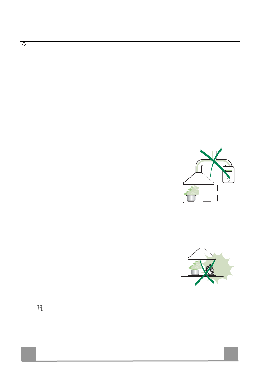
RECOMMENDATIONS AND SUGGESTIONS
The Instructions for Use apply to several versions of this appliance. Accord-
ingly, you may find descriptions of individual features that do not apply to
your specific appliance.
INSTALLATION
• The manufacturer will not be held liable for any damages resulting from incorrect or improper installation.
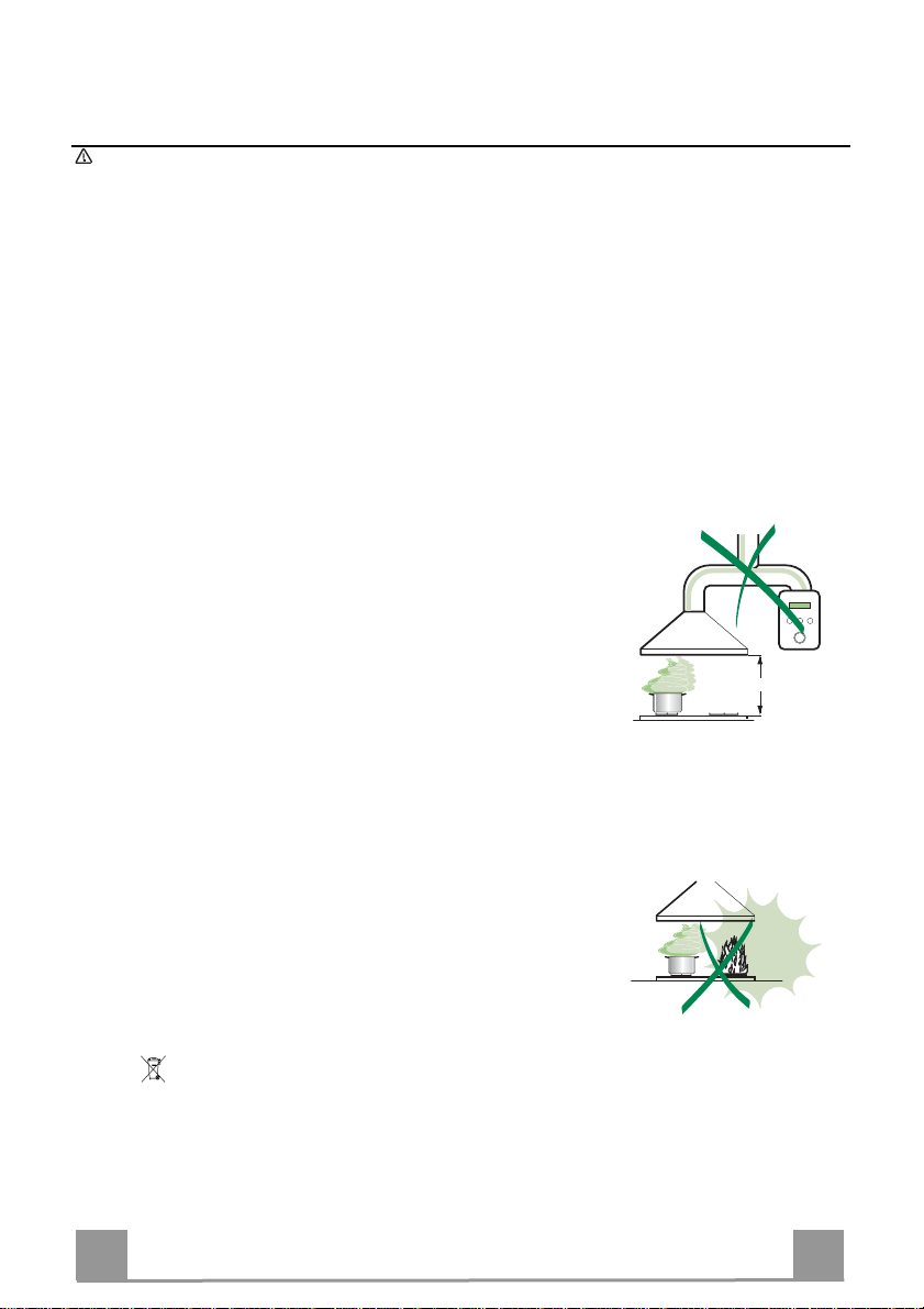
• The minimum safety distance between the cooker top and the extractor
hood is 650 mm (some models can be installed at a lower height, please refer to the paragraphs on working dimensions and installation).
• Check that the mains voltage corresponds to that indicated on the rating
plate fixed to the inside of the hood.
• For Class I appliances, check that the domestic power supply guarantees
adequate earthing.
Connect the extractor to the exhaust flue through a pipe of minimum diame-
ter 120 mm. The route of the flue must be as short as possible.
• Do not connect the extractor hood to exhaust ducts carrying combustion
fumes (boilers, fireplaces, etc.).
• If the extractor is used in conjunction with non-electrical appliances (e.g. gas
burning appliances), a sufficient degree of aeration must be guaranteed in
the room in order to prevent the backflow of exhaust gas. The kitchen must
have an opening communicating directly with the open air in order to
guarantee the entry of clean air.
USE
• The extractor hood has been designed exclusively for domesti c use to eliminate kitchen smells.
• Never use the hood for purposes other than for which it has been designed.
• Never leave high naked flames under the hood when it is in operation.
• Adjust the flame intensity to direct it onto the bottom of the pan only, making
sure that it does not engulf the sides.
• Deep fat fr yers must be continuously monitored during use: overheated oil
can burst into flames.
• Do not flambè under the range hood; risk of fire
• This appliance is not intended for use by persons (including children) with
reduced physical, sensory or mental capabilities, or lack of experience and
knowledge, unless they have been given supervision or instruction concerning use of the appliance by a person responsible for their safety.
• Children should be supervised to ensure that they do not play with the appliance.
MAINTENANCE
• Switch off or unplug the appliance from the mains supply before carrying out
any maintenance work.
• Clean and/or replace the Filters after the specified time period (Fire hazard).
• Clean the hood using a damp cloth and a neutral liquid detergent.
The symbol on the product or on its packaging indicates that this product may not be treated
as household waste. Inst ead it shall be handed over t o the applicable collection point for the
recycling of electrical and electr on ic e quipm e nt. By ens ur ing t his pr od uct is disp os ed of c orr ect ly,
you will help prevent potent ial negative consequences for t he environment and human healt h,
which could otherwise be caused by inappropriate waste handling of this product. For more
detailed information about recycling of this product, please contact your local city office, your
household waste disposal service or the shop where you purchased the product.
EN
3
3
Page 4

CHARACTERISTICS
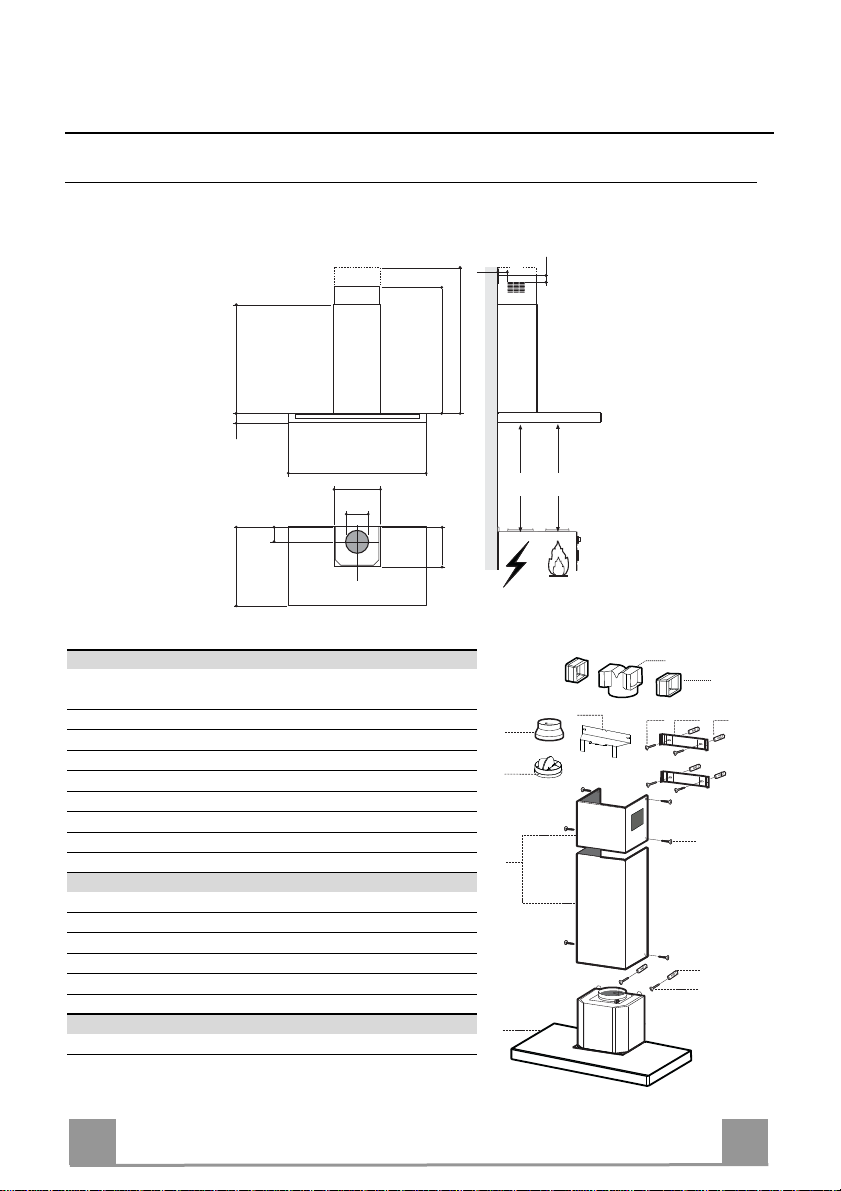
Dimensions
540
898
300
150
108
490 60
680
260
Components
Ref. Q.ty Product Components
1 1 Hood Body, complete with: Controls, Light, Blower,
Filters
2 1 Telescopic Chimney comprising:
2.1 1 Upper Section
2.2 1 Lower Section
9 1 Reducer Flange ø 150-120 mm
10 1 Damper ø 150
14.1 2 Air Outlet Connection Extension
15 1 Air Outlet Connection
Ref. Q.ty Installation Components
7.2.1 2 Upper Chimney Section Fixing Brackets
7.3 1 Air Outlet Connection Support
11 6 Wall Plugs
12a 6 Screws 4,2 x 44,4
12c 6 Screws 2,9 x 9,5
Q.ty Documentation
1 Instruction Manual
EN
Min.
650mm
42
Min.
650mm
64
940
15
14.1
9
7.3
10
2.1
2
2.2
1
12a
7.2.1 11
12c
11
12a
4
4
Page 5
INSTALLATION
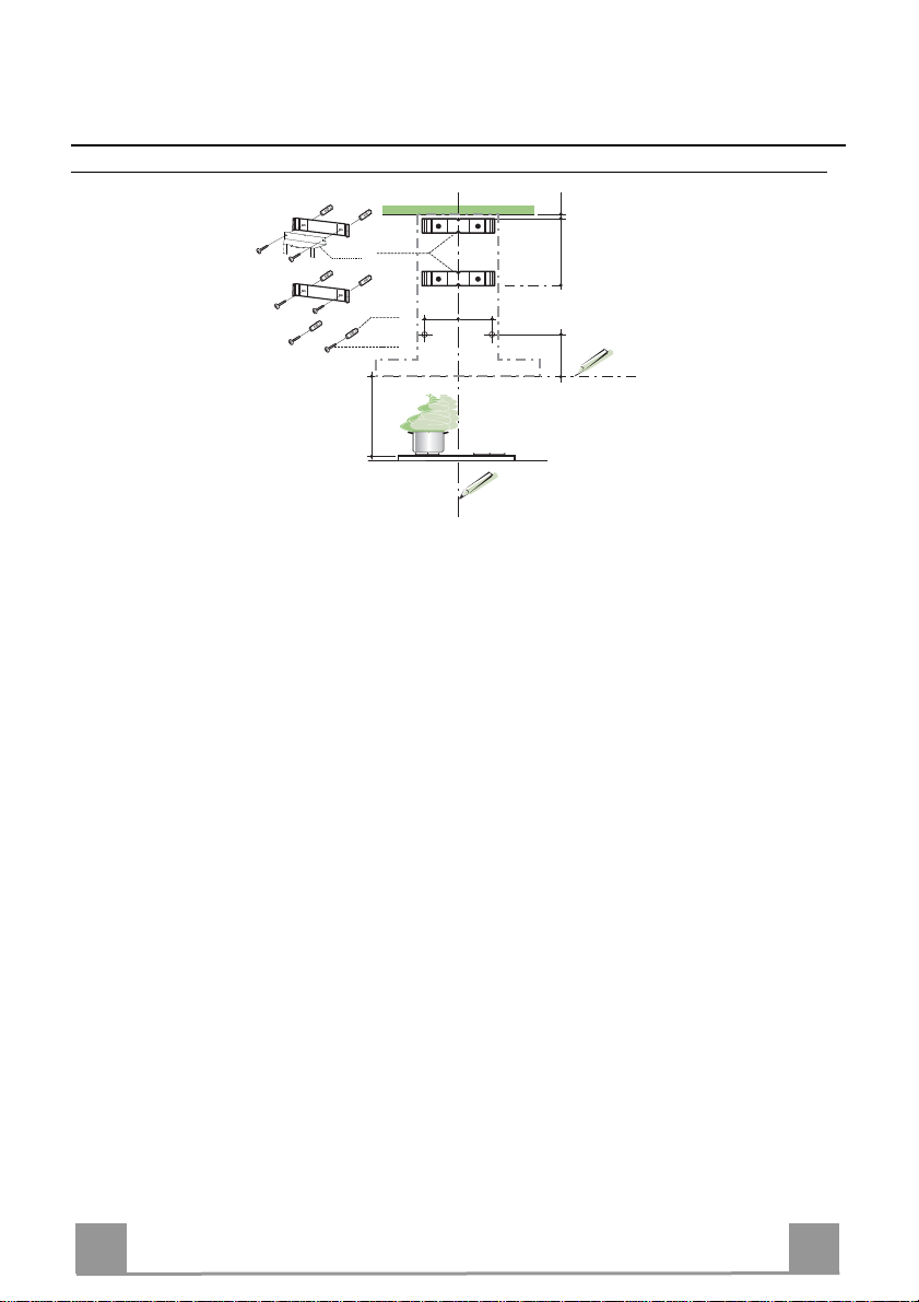
Wall drilling and bracket fixing
7.2.1
7.3
1÷2
X
116
116
11
12a
320
650 min.
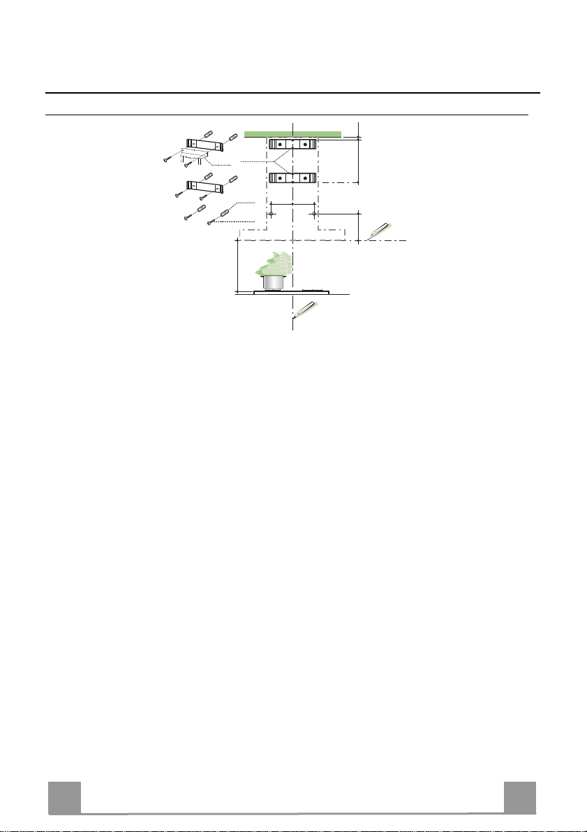
Wall marking:
• Draw a vertical line on the supporting wall up to the ceiling, or as high as practical, at the
centre of the area in which the hood will be installed.
• Draw a horizontal line at 650 mm above the hob.
• Place bracket 7.2.1 on the wall as shown about 1-2 mm from the ceiling or upper limit aligning the centre (notch) with the vertical reference line.
• Mark the wall at the centres of the holes in the bracket.
• Place bracket 7.2.1 on the wall as shown at X mm below the first bracket (X = height of the
upper chimney section supplied), aligning the centre (notch) with the vertical line.
• Mark the wall at the centres of the holes in the bracket.
• Mark a reference point as indicated at 116 mm from the vertical reference line and 320 mm
above the horizontal reference line.
• Repeat this operation on the other side.
• Drill ø 8 mm holes at all the centre points marked.
• Insert the wall plugs 11 in the holes.
• Fix the lower bracket 7.2.1 using the 12a screws (4,2 x 44,4) supplied.
• Fix the upper bracket 7.2.1 and the air outlet connection support 7.3 together using the 2
screws 12a (4,2 x 44,4) supplied.
• Insert the two screws 12a (4,2 x 44,4) supplied in the hood body fixing holes, leaving a gap
of 5-6 mm between the wall and the head of the screw.
EN
5
5
Page 6
12a
Vr
9
ø 120ø 150
10
10
ø 150
15
14.1
7.3
Mounting the hood body
• Before attaching the hood body, tighten the two screws Vr located on the hood body mounting points.
• Hook the hood body onto the screws 12a.
• Fully tighten the support screws 12a.
• Adjust the screws Vr to level the hood body.
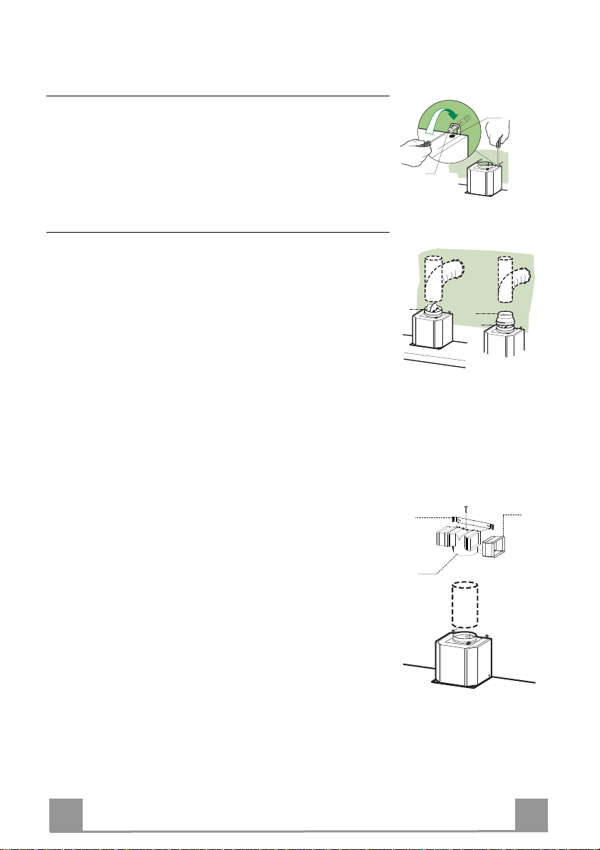
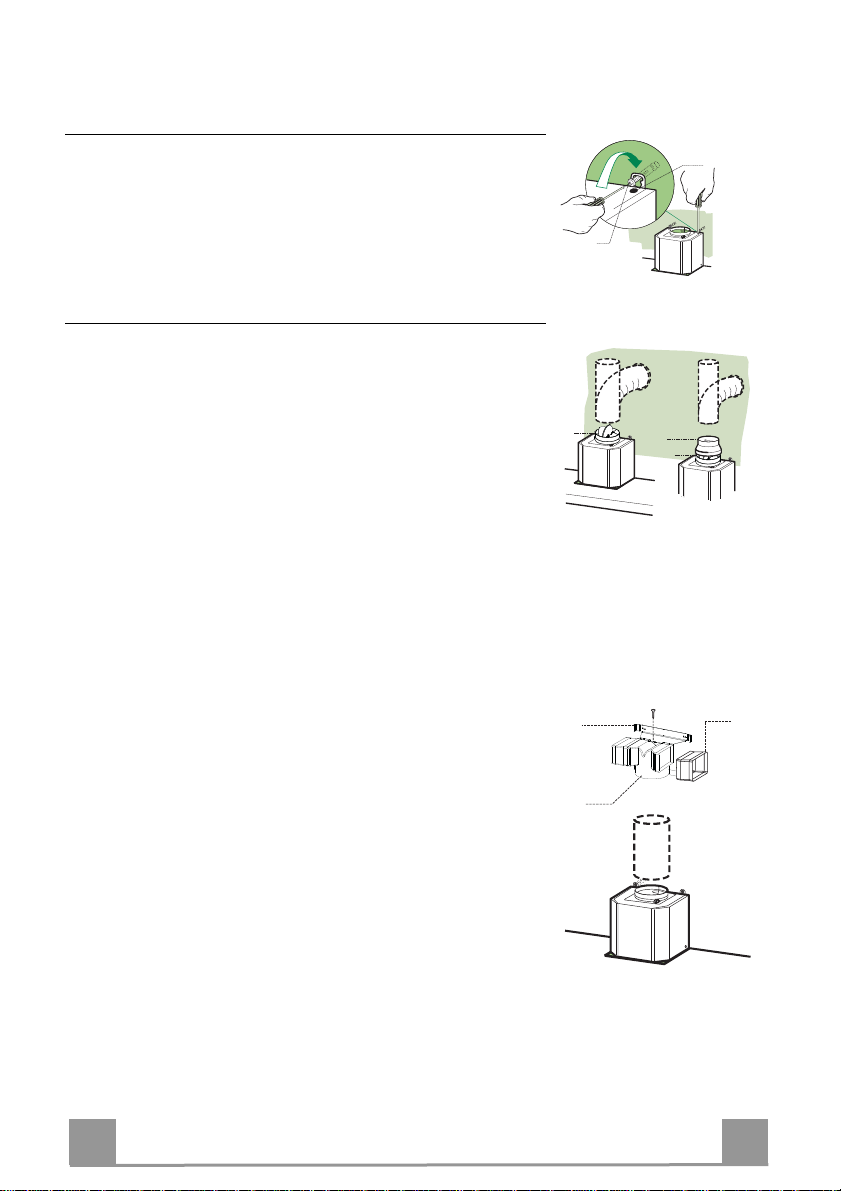
Connections
DUCTED VERSION AIR EXHAUST SYSTEM
When installing the ducted version, connect the hood to the
chimney using either a flexible or rigid pipe ø 150 or 120mm, the
choice of which is left to the installer.
To install a ø 150 pipe
• To install the dumper 10
• Fix the pipe in position using sufficient pipe clamps (not supplied).
To install a ø 120 pipe
• To install a ø 120 mm air exhaust connection, insert the reducer flange 9 on the dumper 10.
• Fix the pipe in position using sufficient pipe clamps (not supplied).
• Remove any activated charcoal filters.
RECIRCULATION VERSION AIR OUTLET
• Insert the connection extension pieces laterally 14.1 in connection 15.
• Insert the Connector 15 into the Support bracket 7.3 and fix it
with a screw.
• Make sure that the outlet of the extension pieces 14.1 is horizontally and vertically aligned with the chimney outlets.
• Connect the air outlet connection 15 to the hood body outlet
using either a flexible or rigid pipe ø 150 mm, the choice of
which is left to the installer.
• Ensure that the activated charcoal filters have been inserted.
EN
6
6
Page 7
12c
2.1
2.2
2
7.2.1
12c
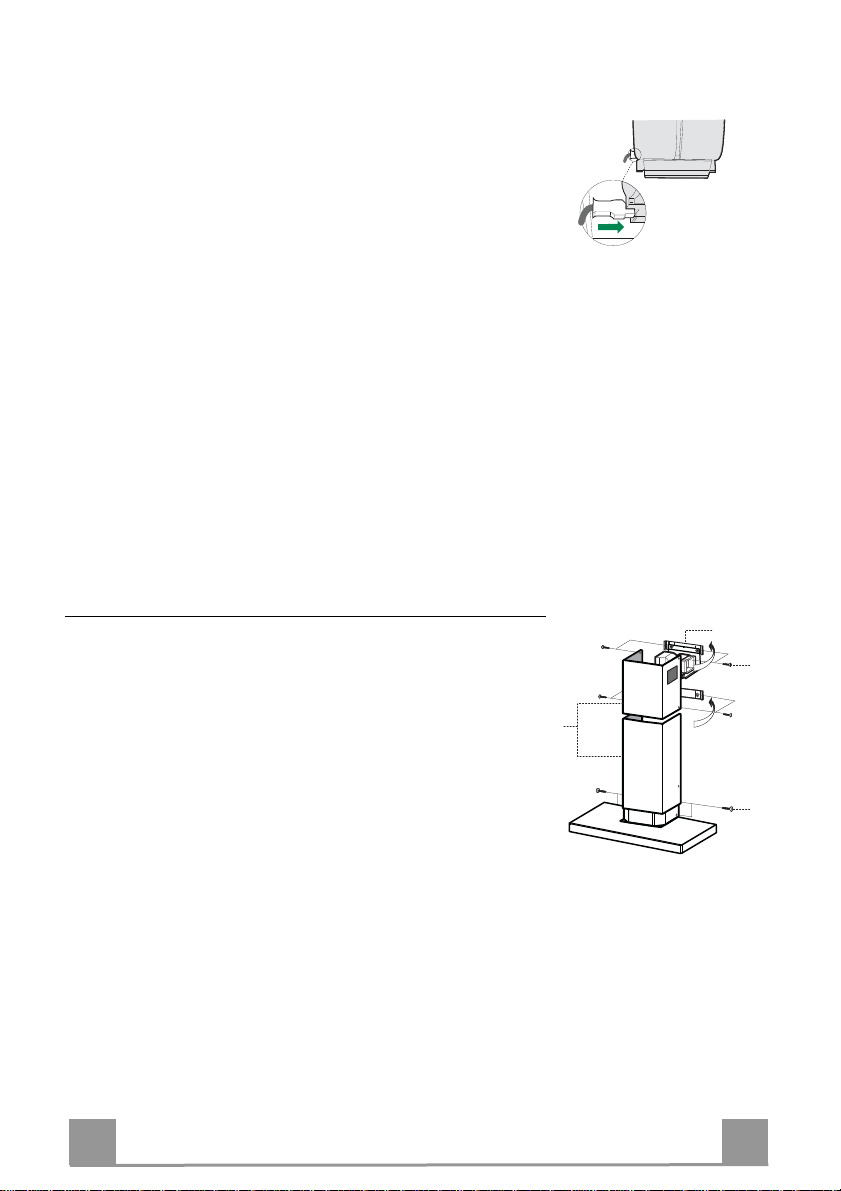
ELECTRICAL CONNECTION
• Connect the hood to the mains through a two-pole switch having a contact gap of at least 3 mm.
• Remove the grease filters (see paragraph Maintenance) being
sure that the connector of the feeding cable is correctly inserted
in the socket placed on the side of the fan.
Flue assembly
Upper exhaust flue
• Slightly widen the two sides of the upper flue and hook them
behind the brackets 7.2.1, making sure that they are well
seated.
• Secure the sides to the brackets by using the 4 screws 12c (2,9
x 9,5) supplied.
• Make sure that the outlet of the extensions pieces is aligned
with the chimney outlets.
Lower exhaust flue
• Slightly widen the two sides of the flue and hook them between the upper flue and the wall, making sure that they are
well seated.
• Fix the lower part laterally to the hood body by using the 2
screws 12c (2,9 x 9,5) supplied.
EN
7
7
Page 8
USE
T1
T2
T3
L
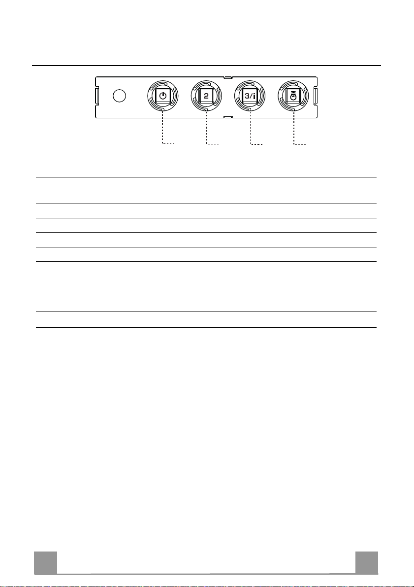
Control panel
BUTTON LED FUNCTIONS
T1 Speed On Turns the Motor on at Speed one.
Turns the Motor off.
T2 Speed On Turns the Motor on at Speed two.
T3 Speed Fixed When pressed briefly, turns the Motor on at Speed three.
Flashing Pressed for 2 Seconds.
Activates Speed four with a timer set to 10 minutes, after
which it returns to the speed that was set previously. Suitable
to deal with maximum levels of cooking fumes.
L Light Turns the Lighting System on and off.
Warning: Button T1 turns the motor off, after first passing to speed one.
EN
8
8
Page 9
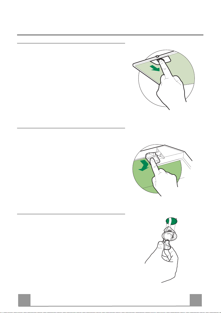
MAINTENANCE
Grease filters
CLEANING METAL SELF- SUPPORTING GREASE FILTERS
• The filters must be cleaned every 2 months of operation, or more frequently for particularly heavy usage,
and can be washed in a dishwasher.
• Remove the filters one at a time by pushing them towards the back of the group and pulling down at the
same time.
• Wash the filters, taking care not to bend them. Allow
them to dry before refitting.
• When refitting the filters, make sure that the handle
is visible on the outside.
Activated charcoal filter (Recirculation version)
REPLACING THE ACTIVATED CHARCOAL FILTER
• The filter is not washable and cannot be regenerated,
and must be replaced approximately every 4 months
of operation, or more frequently for particularly
heavy usage.
• Remove the metal grease filters.
• Remove the saturated activated carbon filter by releasing the fixing hooks.
• Fit the new filter by hooking it into its seating.
• Refit the metal grease filters.
Lighting
LIGHT REPLACEMENT
20 W halogen light.
• Remove the 2 screws fixing the Lighting support, and
pull it out of from the Hood.
• Extract the lamp from the Support.
• Replace with another of the same type, making sure
that the two pins are properly inserted in the lamp
holder socket holes.
• Refit the Support, fixing it in place with the two
screws removed as above.
EN
9
9
Page 10
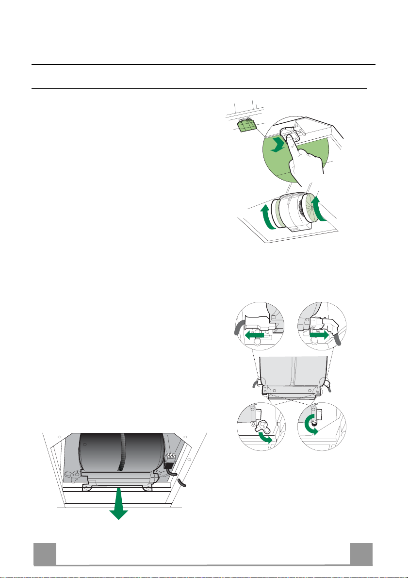
EASY CLEANING TM
Removing the Grease Filters
Before carrying out Maintenance on the
EASY CLEANING Suction Unit:
• Disconnect the hood by switching off the
twopole switch on the mains power supply
line, or by switching off the main power
switch.
• Remove the grease filters from the hood.
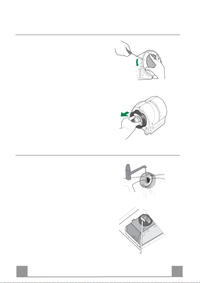
• If the hood is of the recirculation ty pe, remove the odour filters:
• For hoods with a flat cartridge (A): turn the
fastening elements provided;
• For hoods with a bayonet cartridge (B):
turn as indicated and extract.
Disconnecting the EASY CLEANING Suction Unit
• Disconnect the power connector Ca and the
control and lighting connector Cmd on the
sides of the unit.
• For wall-mounted hoods and free-standing
hoods with square chimney, turn the levers
Lb locking the suction unit, so that they
disconnect from the pins.
• For free-standing hoods with round chimney, unscrew the plugs Vb locking the suction unit.
• Pull the suction unit forwards so that it unhooks from the support pins, and remove it
downwards through the air outlet.
A
B
CmdCa
Lb
Vb
EN
1
10
Page 11
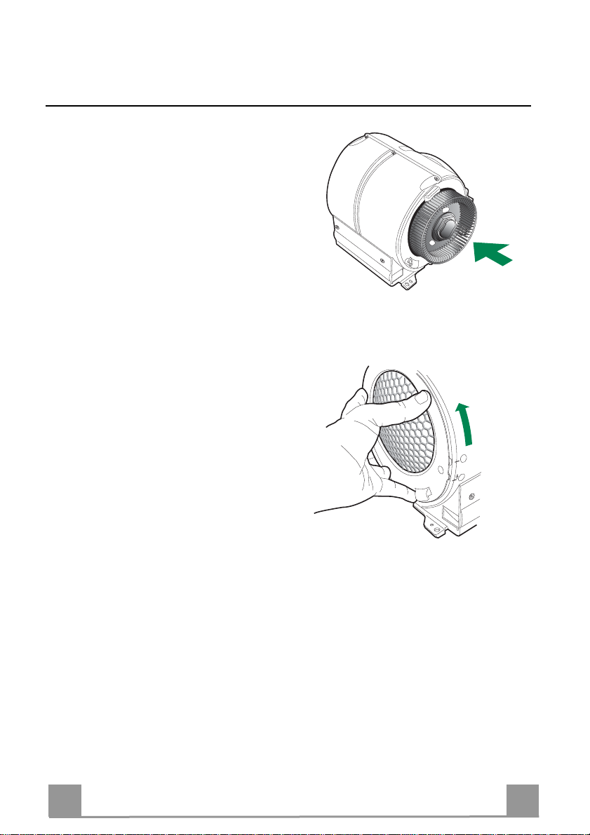
Dismantling Washable Parts
• To remove the side grilles protecting the
fans, lift up the stop tooth using a knife or
screwdriver and turn the grilles in the direction indicated by the arrow.
• Grasp the fans in the holes provided and
pull to extract.
CLEANING
O
LOCK
P
E
N
FREE
• Wash the fans and the protection grilles,
using normal washing-up liquid. These
elements can also be washed in the dishwasher.
• Using a damp cloth and a suitable detergent, clean the body of the suction device,
taking great care not to allow any water to
leak into the inside of the unit or into the
connector housings.
• Leave until completely dry bifore reassembling.
• Using a brush, clean the air outlet pipe as
far as you can reach.
EN
1
11
Page 12
REASSEMBLY
N.B. To avoid reassembling the wrong way
round, the two fans have different couplings.
• Reassemble the fans on the corresponding
pins, pressing them until they snap into
place.
• Fit the protection grilles so that the teeth
coincide in the “FREE” position and when
turned to “LOCK”.
• Replace the EASY CLEANING suction
unit on the hood, inserting it in position and
connecting it to the support pins.
• Turn the lock levers, or screw in the lock
plugs.
• Connect the power connector and the
command connector to the sockets on the
sides of the suction device.
• Replace any activated charcoal odour filters.
• Replace the grease filters.
• Connect the hood to the power supply system, by turning the two-pole switch on the
mains power line to on, or by turning the
main switch on.
• Check that the hood is working properly,
by turning the motor and lighting on.
LOCK
O
P
E
N
FREE
EN
1
12
Page 13
650 mm min.
RÅD OG ANVISNINGER
Denne brugervejledning gælder for flere versioner af apparatet.
Der fremstilles muligvis enkelte dele af tilbehøret, der ikke vedrører jeres apparat.
INSTALLATION
• Producent en kan ikke holdes ansvarlig for eventuelle skader, der skyldes ukorrekt
eller forkert installation.
• Den mindst tilladelige sikkerhedsafstand mellem komfurets top og emhættens underside er 650 mm (nogle modeller kan installeres lavere, jævnfør afsnittene vedrørende
ydre mål og installation).
• Kontrollér, at lysnetspændingen er den samme som den spænding, der er angivet
mærkepladen, der sidder på inde i emhætten.
• For Klasse I apparater skal det også kontrolleres, at elforsyningen er forsynet med
jord.
• Emhætten kobles til aftrækskanalen ved hjælp af et rør med en min.-diameter på 120
mm. Afstanden fra emhætten til kanalen skal være så kort som mulig.
• Emhætten må ikke tilsluttes en kanal, der fører forbrændingsgasser ud i det fri (oliefyr, brændeovne etc.).
• Hvis emhætten skal anvendes i forbindelse med ikke-elektriske apparater (f.eks.
gaskomfur, gaskogeblus), skal det sikres, at lufttilgangen til rummet er tilstrækkelig,
så aftræksgasserne ikke slår tilbage. Køkkenet skal have en åbning, der har direkte
forbindelse til det fri, så der er sikret en tilstrækkelig mængde ren luft.
ANVENDELSE
• Emhætten er udelukk ende beregnet til at fjerne em og lugte i køkkener i private husholdninger.
• Emhætten må kun anvendes til det formål, hvortil den er konstrueret.
• Der må ikke forekomme høj åben ild under emhætten, mens den anvendes.
• Justér brænderen, så flammerne er rettet direkte mod bunden af panden/gryden – de
må ikke nå ud over kanten af bunden.
• Frituregryder skal under brug holdes under konstant opsyn: kogende varm olie kan
sprøjte ind i flammerne.
• Emhætten må ikke anvendes af børn og personer, som ikke ved, hvordan den betjenes.
• Apparatet er ikke beregnet til at skulle anvendes af mindre børn eller svækkede personer uden opsyn.
• Undlad at flambere retter under emhætten; der opstår ellers brandfare.
• Dette apparat må ikke anvendes af personer (derunder børn) med nedsatte psykiske,
sensoriske eller sindsmæssige evner, eller personer uden erfaring eller tilstrækkeligt
kendskab, med mindre de overvåges eller oplæres i brug af apparatet af personer,
der er ansvarlige for deres sikkerhed.
• Børn skal overvåges for at undgå, at de leger med apparatet.
VEDLIGEHOLDELSE
• Inden apparatet skal vedligeholdes eller rengøres, skal der slukkes for det eller stikket skal tages ud af stikkontakten.
• Rengør og/eller udskift filtrene iht. det angivne tidinterval (Brandbare).
• Rengør emhætten ved hjælp af en fugtig klud og et neutralt flydende rengøringsmiddel.
Symbolet på produktet ell er på pakken angiver, at dette p rodukt ikke må behandles som hu sholdningsaffald. Det skal i stedet o vergives til en affal dsstation for behandli ng af elektrisk og elekt ronisk udstyr. Ved at sørge for at dett e produkt blive r bortskaffet på den rette måde, hj ælper du med ti l
at forebygge eventuelle negative påvirkninger af miljøet og af personers helbred, der ellers kunne
forårsages af forkert bortskaffel se af dett e produkt . Kontakt det l okale kom munekontor, affalds selskab
eller den forretning, hvor produ kt er købt, for yderli gere oplysninger om gen anvendelse af dette produkt.
DK
1
13
Page 14
APPARATBESKRIVELSE
Dimensioner
540
898
300
150
108
490 60
680
260
Komponenter
Ref. Stk. Produktets komponenter
1 1 Emhættens hoveddel inkl.: Betjeningsanordninger, lys,
ventilatorenhed, filtre
2 1 Teleskopaftræk bestående af:
2.1 1 Øverste aftræk
2.2 1 Nederste aftræk
9 1 Passtykke ø 150-120 mm
10 1 Sidestykke med ventil
14.1 2 Forlænger til luftudstrømnings overgangsstykke
15 1 Luftudstrømnings overgangsstykke
Ref. Stk. Installationsdele
7.2.1 2 Beslag til befæstigelse af øverste aftræk
7.3 1 Støttebeslag til overgangsstykket
11 6 Forankringer
12a 6 Skruer 4,2 x 44,4
12c 6 Skruer 2,9 x 9,5
Stk. Dokumentation
1 Brugerhåndbog
DK
Min.
650mm
42
Min.
650mm
64
940
15
14.1
9
7.3
10
2.1
2
2.2
1
12a
7.2.1 11
12c
11
12a
1
14
Page 15
INSTALLATION
Boring i væg og befæstigelse af beslag
7.2.1
7.3
1÷2
X
116
116
11
12a
320
650 min.
På væggen skal der afmærkes:
• en lodret linje op til loftet eller den øverste grænse, i midten af emhættens monteringsområde;
• en vandret linje mindst 650 mm over kogepladen.
• Placér beslaget 7.2.1 som vist, d.v.s. 1-2 mm fra loftet eller den øverste grænse, og stil dets
midte (indskæringer) på lige linje med den lodrette referencelinje.
• Afmærk midten af hullerne i beslaget.
• Placér beslaget 7.2.1 som vist, X mm under det første beslag (X=højden på det øverste af-
træk, der følger med), og stil dets midte (indskæringer) på lige linje med den lodrette referencelinje.
• Afmærk midten af hullerne i beslaget.
• Afmærk so m vist en reference 116 mm fra den lodrette referencelinje, 320 mm over den
vandrette referencelinje.
• Gør det samme på den anden side.
• Bor et hul med ø 8 mm på de afmærkede steder.
• Sæt forankringerne 11 i hullerne.
• Fastgør det nederste beslag 7.2.1 ved hjælp af de medfølgende skruer 12a (4,2 x 44,4 ).
• Fastgør det øverste beslag 7.2.1 og overgangsstykkets støttebeslag 7.3 ved hjælp af de 2
medfølgende skruer 12a (4,2 x 44,4).
• Skru de 2 medfølgende skruer 12a (4,2 x 44,4) fast i hullerne til fastgøring af emhættens
hoveddel, hvorved der skal sikres en afstand på 5-6 mm mellem væggen og skruens hoved.
DK
1
15
Page 16
12a
Vr
9
ø 120ø 150
10
10
ø 150
15
14.1
7.3
Montering af emhætte
• Inden man hænger emhætten op, skal man stramme de to skruer Vr, som sidder i hættens ophængningspunkter.
• Hæng emhætten op på de forberedte skruer 12a.
• Stram ophængningsskruerne 12a helt til.
• Ved at dreje på skruerne Vr nivelleres emhætten.
Tilslutninger
VERSION FORBUNDET TIL AFTRÆKSKANAL
Når aftrækskanal-versionen opsættes, forbindes emhætteenheden
til kanalen med en flexslange eller et hårdt rør, Ø150 eller 120
mm – valget er op til den, der opsætter emhætten.
Tilslutning af rør på ø 150
• Indsæt studsen på ø 150 10 på emhættens udsugningshul.
• Spænd røret fast med specielle rørklemmer. Disse medleveres
ikke.
Tilslutning af rør på ø 120
• Ved tilslutning af rør på ø120 mm, indsættes reduktionsstudsen
9 på studsen ø 150, som er monteret tidligere.
• Spænd røret fast med specielle rørklemmer. Disse medleveres
ikke.
• I begge tilfælde skal man fjerne eventuelle lugtabsorberende
kulfiltre.
LUFTUDSTRØMNING PÅ FILTRERENDE VERSION
• Før overgangsstykkets forlængere 14.1 ind på siden af overgangsstykket 15.
• Før overgangsstykket 15 ind i støttebeslaget 7.3, og spær det
fast med en skrue.
• Sørg for at udgangen på overgangsstykkets forlængere 14.1
befinder sig ud for aftrækkets mundinger, både vandret og lodret.
• Forbind overgangsstykket 15 til emhættens hoveddels udgang
ved hjælp af et rør eller en flexslange med ø150, som det påhviler installatøren at vælge.
• Sørg for, at lugtfiltret med aktivt kul er monteret.
DK
1
16
Page 17

12c
2.1
2.2
2
7.2.1
12c
TILSLUTNING TIL STRØMFORSYNING
• Tilslut emhætten til elnettet, idet der indsættes en topolet afbryder med en kontaktafstand på mindst 3 mm.
• Fjern fedtfiltrene (se afsnittet ”Vedligeholdelse”) og kontroller,
at eltilslutningens kabelklemme er korrekt indsat i udsugningsgruppens stik.
Montering af aftræk
Øverste aftræk
• Skub de to sideflapper lidt ud, sæt dem fast bag ved beslagene
7.2.1, og luk dem til igen, helt til stoppet.
• Fastgør dem på siden af beslagene ved hjælp af de 4 medfølgende skruer 12c (2,9 x 9,5 ).
• Sørg for at udgangen på overgangsstykkets forlængere befinder
sig ud for aftrækkets mundinger.
Nederste aftræk
• Skub aftrækkets sideflapper lidt ud, sæt dem fast mellem det
øverste aftræk og væggen, og luk dem igen, helt til stoppet.
• Fastgør undersiden på siden af emhættens hoveddel ved hjælp
af de 2 medfølgende skruer 12c (2,9 x 9,5 ).
DK
1
17
Page 18

BRUG
T1
T2
T3
L
Betjeningspanel
TAST KONTROLLAMPER FUNKTIONER
T1 Hastighed Tændt Tænder motoren ved 1. hastighed.
Slukker motoren.
T2 Hastighed Tændt Tænder motoren ved 2. hastighed.
T3 Hastighed Konstant Et kortvarigt tryk tænder motoren ved 3. hastighed.
Blinkende Trykket nede i 2 sekunder.
Aktiverer den 4. hastighed (tidsindstillet til 10
minutter). Herefter genetableres den hastighed, der
var indstillet forudgående. Er i stand til at klare selv
den kraftigste os fra madlavningen.
L Lys Tænder og slukker lyset.
Advarsel: Tasten T1 slukker motoren ved altid at gå til 1. hastighed.
DK
1
18
Page 19

VEDLIGEHOLDELSE
Fedtfiltre
RENGØRING AF SELVBÆRENDE FEDTFILTRE AF METAL
• Filtrene skal rengøres efter 2 måneders drift, eller
oftere ved kraftig anvendelse, og de kan vaskes i opvaskemaskine.
• Fjern filtrene på én gang ved at skubbe dem mod det
bageste af gruppen og træk dem ned på samme tid.
• Vask filtrene og pas samtidig på ikke at bøje dem.
Lad dem tørre, inden de fastgøres igen.
• Når filtrene fastgøres igen, skal du sørge for, at håndtaget er synligt udefra.
Aktivt kulfilter (recirkulationsudgave)
UDSKIFTNING AF DET AKTIVE KULFILTER
• Filteret kan ikke vaskes og kan ikke regenereres, og
skal udskiftes omkring hver fjerde måned, eller oftere
ved kraftig brug.
• Tag fedtfiltrene af metal ud
• Tag det gennemvædede aktive kulfilter ud ved at løsne befæstelseskrogene.
• Fastgør det nye filter ved at hægte ind på plads
• Sæt metalfedtfiltrene på plads igen.
Belysning
UDSKIFTNING AF PÆRER
20W halogenpærer.
• Fjern de 2 skruer, som fastholder fatningen og tag
den ud af emhætten.
• Tag pæren ud af fatningen.
• Skift den ud med en ny af samme slags, idet man sørger for at indsætte de to spidser korrekt i fatningen.
• Montér fatningen igen ved hjælp af de to skruer.
DK
1
19
Page 20

EASY CLEANING TM
Udtagning af fedtfiltre
Før man går i gang med vedligeholdelsen af
EASY CLEANING udsugningsenheden:
• Frakobl emhætten ved at aktivere den topolede afbryder, der er installeret på netforsyningen, eller hovedafbryderen.
• Fjern fedtfiltrene fra emhætten.
• Fjern lugtfiltrene, hvis det drejer sig om
den filtrerende version af emhætten:
• Hvis emhætten er forsynet med flad indsats
(A): Indvirk på de dertil beregnede hager;
• Hvis emhætten er forsynet med bajonetindsats (B): Drej som vist på billedet, og tag
den ud.
Frakobling af EASY CLEANING udsugningsenheden
• Frakobl forsyningskonnektoren Ca og betjeningsanordningernes og belysningens
konnektor Cmd på enhedens sider.
• På vægmonterede emhætter og emhætter
over kogeøer med rektangulært aftræk, skal
udsugningsenhedens spærregreb Lb drejes
og frakobles tappene.
• På emhætter over kogeøer med rundt aftræk, skal udsugningsenhedens spærhager
Vb løsnes.
• Træk udsugningsenheden frem, så den frakobles støttetappene, og tag den ud via
luftudgangen, i nedadgående retning.
A
B
CmdCa
Lb
Vb
DK
2
20
Page 21

Afmontering af de dele, der kan vaskes
• Sideristene, der beskytter rotorerne, fjernes
ved at hæve spærrehakkene med spidsen af
en skruetrækker eller en kniv og dreje dem
i pilens retning.
• Tag fat i rotorerne i hullerne, og træk dem
ud.
RENGØRING
• Vask rotorerne og beskyttelsesristene med
et almindeligt opvaskemiddel. De kan også
vaskes i opvaskemaskine.
• Rens udsugningsanordningens hoveddel
med en fugtig klud og et egnet rengøringsmiddel; pas på, at der ikke trænger vand ind
i enheden og konnektorernes sæder.
• Lad den tørre godt, før den sættes på plads
igen.
• Rens luftudgangsrøret så langt ind som muligt med en gulvskrubbe.
O
LOCK
P
E
N
FREE
DK
2
21
Page 22

GENMONTERING
OBS: For at undgå at bytte om på rotorerne,
når de sættes på plads igen, er deres tilkoblingssteder forskellige.
• Sæt rotorerne tilbage på de tilsvarende tappe, idet der presses, indtil der høres et klik.
• Montér beskyttelsesristene, idet hakkene i
positionen ”FREE” skal befinde sig ud for
hinanden, og drej dem over mod ”LOCK”.
• Sæt EASY CLEANING udsugningsenheden på emhætten igen ved at placere den og
koble den fast til støttetappene.
• Drej spærregrebene eller stram spærhagerne.
• Forbind forsyningens og betjeningsanordningernes konnektorer med tilkoblingsstederne på siderne af udsugningsanordningen.
• Sæt lugtfiltret med aktivt kul på igen, såfremt det forefindes.
• Sæt fedtfiltrene på igen.
• Tilkobl emhætten netforsyningen ved at
aktivere den topolede afbryder, der er installeret på netforsyningen, eller hovedafbryderen.
• Kontrollér funktionen ved at tænde for motoren og lysene.
LOCK
O
P
E
N
FREE
DK
2
22
Page 23

650 mm min.
REKOMMENDATIONER OCH TIPS
Denna bruksanvisning är förutsedd för flera versioner av apparaten.
Det är möjligt att vissa enskilda utrustningsdetaljer, inte berör din apparat.
INSTALLATION
• Tillverkaren åtar s ig inget ansvar fö r fel som beror på felaktig eller olämplig installation.
• Minsta tillåtna avstånd mellan spishäll och köksfläk t är 650 mm (vissa modeller
kan installeras på en lägre höjd, se avsnitten mått och installation).
• Kontrollera att matn ingsnätets spänning motsvarar den som anges på märkskylten inuti köksfläkten.
• För Klass I-apparater, kontrollera att matningsnätet ger effektiv jordning.
• Anslut fläkten till frånluftkanalen via ett rör med e n diameter på minst 120 mm.
Anslutningsröret skall hållas så kort som möjligt.
• Anslut inte köksfläkte n till frånluf tkanaler som leder förb ränningsgaser (från pannor, eldstäder etc.).
• Om fläkten används tillsammans med icke-elektriska spisar (t.ex. gasspisar) måste tillräcklig ventilation garanteras i lokalen för att förhind ra backflöde av förbränningsgaser. Köket måste ha ett tilluftdon med direkt anslutning mot ytterluft för att
garantera inflöde av friskluft.
ANVÄNDNING
• Köksfläkten är uteslutande avsedd för hemanvändning, för att eliminera köksos.
• Använd aldrig köksfläkten för andra ändamål än det avsedda.
• Undvik höga flammor under köksfläkten medan fläkten är i drift.
• Justera gaslåg an så att flammorna endast berör kokkärlets undersida och inte
tränger upp längs dess sidor.
• Fritöser mås te övervakas kontinuerligt under användning: Överhettad olja kan
fatta eld.
• Köksfläkten skall inte användas av barn elle r personer som inte är insatta i ko rrekt användning.
• Apparaten är inte avsedd att användas av barn eller handikappade personer utan
övervakning.
• Tillaga inga flamberade maträtter under köksfläkten, då det finns risk för eldsvåda
• Denna apparat får inte användas av personer (inklusiv e barn) med nedsatta fysiska, sensoriska eller mentala förmågor, eller av personer utan erfarenhet och
kunskap, om inte de är kontrollerade eller instruerade om användningen av apparaten av personer ansvariga för deras säkerhet.
• Barn ska övervakas för att sä kerst äll a att de int e lek er med a ppar ate n.
UNDERHÅLL
• Stäng av apparaten eller skilj den från matningsnätet innan något underhållsarbete utförs.
• Rengör och/eller byt filtren med angivet intervall (Risk för eldsvåda).
• Rengör köksfläkten med en fuktig trasa och neutralt flytande diskmedel.
Symbolen på produkten eller emballag et a nger at t produ kten i nte få r hante ras som h ushål lsavfall. Den skall i stället lämnas in på uppsamlingsplats för återvinning av el- och elektronikkomponenter. Genom att säkerställa att produkten hanteras på rätt sätt bidrar du till att förebygga eventuellt
negativa miljö- och hälsoeffekter som kan uppstå om produkten kasseras som vanligt avfall. För
ytterligare upplysningar om återvi nning bör du k ontakta lok ala myndighete r eller soph ämtningstjän st
eller affären där du köpte varan.
SE
2
23
Page 24

EGENSKAPER
Mått
540
898
300
150
108
490 60
680
260
Komponenter
Ref. Antal Produktkomponenter
1 1 Köksfläkthus, komplett med: manöveranordningar,
lampa, fläkt, filter
2 1 Teleskopisk skorsten bestående av:
2.1 1 Överdel
2.2 1 Underdel
9 1 Reduktionsfläns ø 150-120 mm
10 1 Fläns ø 150 med backventil
14.1 2 Anslutningsstycke för luftutsläpp
15 1 Luftutsläppsgrenrör
Ref. Antal Installationskomponenter
7.3 1 Luftutsläppsgrenrörs konsol
7.2.1 2 Fästvinklar för övre skorstensdel
11 6 Väggpluggar
12a 6 Skruvar 4,2 x 44,4
12c 6 Skruvar 2,9 x 9,5
1 Dokumentation
SE
Min.
650mm
42
Min.
650mm
64
940
15
14.1
9
7.3
10
2.1
2
2.2
1
12a
7.2.1 11
12c
11
12a
2
24
Page 25

INSTALLATION
Borrning i vägg och montering av fästen
7.2.1
7.3
1÷2
X
11
12a
320
116
116
650 min.
Markering på vägg:
• Ett vertikalt streck upp till taket eller max. gränsen, i mitten av köksfläktens monteringsområde.
• Ett horisontellt streck 650 mm ovanför tillagningshällen.
• Placera konsolen 7.2.1 1-2 mm från taket eller den övre gränsen enligt anvisningarna. Ställ
in konsolens mitt (hack) på det vertikala referensstrecket.
• Markera konsolens hål.
• Placera konsolen 7.2.1 X mm under den första konsolen (X = höjd för medföljande övre
skorsten) enligt anvisningarna.Ställ in konsolens mitt(hack)på det vertikala referensstrecket.
• Markera konsolens hål.
• Markera en referenspunkt 116 mm från det vertikala referensstrecket och 320 mm ovanför
det horisontella referensstrecket enligt anvisningarna.
• Upprepa detta moment på den motsatta sidan.
• Borra 8 mm hål i de markerade punkterna.
• Sätt in expansionspluggarna 11 i hålen.
• Fäst den nedre konsolen 7.2.1 med de medföljande skruvarna 12a (4,2 x 44,4).
• Sätt ihop den övre konsolen 7.2.1 och stödkonsolen 7.3 med de medföljande två skruvarna
12a (4,2 x 44,4).
• Skruva fast de två medföljande skruvarna 12a (4,2 x 44,4) i hålen för fastsättning av köksfläktsstommen.Se ti l l a t t l ämna et t u t rymm e p å 5 - 6 m m m el l a n v ä g g e n och skruvhuvudet.
SE
2
25
Page 26

12a
Vr
9
ø 120ø 150
10
10
ø 150
15
14.1
7.3
Montering av köksfläktsstomme
• Innan du hakar fast köksfläktsstommen, skruva fast de 2 skruvarna Vr som sitter i upphängningspunkterna på köksfläktsstommen.
• Haka fast köksfläktsstommen i de förberedda 12a skruvarna.
• Skruva fast 12a stödskruvarna.
• Skruva på skruvarna Vr för att nivellera köksfläktsstommen.
Anslutningar
LUFTUTSLÄPP SUGANDE VERSION
För installation i sugande version anslut fläktkåpan till utgångsrörsystemet med ett styv eller böjlig slang med en diameter på
150 eller 120 mm, valet lämnas åt installatören.
Anslutning till slang med ø 150
• Sätt i flänsen ø 150 10 på utgången av köksfläktsstommen.
• Fäst slangen med lämpliga slangklämmor. Nödvändigt material
medföljer inte.
Anslutning till slang med ø 120
• För anslutning med en slang med 120 mm diameter, sätt i reduktionsflänsen 9 på den tidigare installerade ø 150 flänsen.
• Fäst slangen med lämpliga slangklämmor. Nödvändigt material
medföljer inte.
• I båda fallen avlägsna eventuella luktfilter med aktivt kol.
KOLFILTER
• För in förlängningsstyckena 14.1 i grenröret 15.
• Sätt i anslutningen 15 i stödkonsolen 7.3 och fäst den med en
skruv.
• Kontrollera att förlängningsstyckna sitter horisontelt och vertikalt uppriktade. Om så inte är fallet justera detta.
• Anslut grenröret 15 till köksfläkten genom att anvä’nda en fast
eller en flexibel slang.
• Montera dit kolfilter
SE
2
26
Page 27

12c
2.1
2.2
2
7.2.1
12c
ELEKTRISK ANSLUTNING
• Anslut fläktkåpan till eluttaget och installera en tvåpolig brytare med en öppning på minst 3 mm emellan kontakterna.
• Avlägsna fettfiltren (se avsnitt “Underhåll”) och se till att nätsladdens kontaktdon är rätt isatt i fläktens uttag
MONTERING AV SKORSTEN
Skorsten, övre sektion
• För försiktigt två motstående sidor av den övre skorstensdelen
utåt och haka dem på fästena 7.2.1. Se till att de sitter ordentligt.
• Fixera sidorna mot fästena med hjälp av de 4 skruvarna 12c
som medföljer.
• Kontrollera att förlängningsstyckna sitter horisontelt och vertikalt uppriktade. Om så inte är fallet justera detta.
Skorsten, nedre sektion
• För försiktigt två motstående sidor av den nedre skorstensdelen
utåt och haka fast dem mellan den övre skorstensdelen och
väggen. Se till att de kommer ordentligt på plats.
• Fixera den undre skorstensdelens sidor mot fläkthuset med
hjälp av de 2 skruvarna 12c (2,9 x 9,5) som medföljer.
SE
2
27
Page 28

ANVÄNDING
T1
T2
T3
L
Kontrollpanel
KNAPP LYSDIOD FUNKTIONER
T1 Hastighet Tänd Aktiverar motorn på den första hastigheten.
Stänger av motorn.
T2 Hastighet Tänd Aktiverar motorn på den andra hastigheten.
T3 Hastighet Fast Om den trycks kort aktiverar den motorn på den tredje
hastigheten.
Blinkande Om den trycks i 2 sekunder.
Aktiveras den fjärde hastigheten tidsinställd på 10 minuter,
när denna tid förflutit återgår systemet till den tidigare
inställda hastigheten. Lämplig att hålla stånd mot max.
spridning av matos.
L Belysning Tänder och släcker belysningen.
VARNING: Knappen T1 stänger av motorn genom att alltid passera den första hastigheten.
SE
2
28
Page 29

UNDERHÅLL
FETTFILTER
RENGÖRNING AV FETTFILTER
• rengöring av fettfilter av metall.
• filtren är diskbara och måste rengöras minst varannan
månad. Rengör oftare vid intensiv användning.
• ta bort filtren, ett i taget, låt dem torka före återmontering.
• vid återmontering av filtren, var noga med att handtagen vänds utåt.
Kolfilter
• byte av kolfilter:
• ta bort fettfiltren av metall
• ta bort de igensatta kolfiltren
• sätt tillbaka fettfiltren av metall
Belysning
BYTE AV LAMPOR
Halogenlampor, 20W
• Ta bort de två skruvarna som fäster lamphållaren och
dra ut den ur köksfläkten.
• Dra ut lampan ur hållaren.
• Byt ut lampan mot en ny med samma egenskaper.
Sätt in de två piggarna korrekt i hållarens säte.
• Montera hållaren på nytt med de två skruvarna.
SE
2
29
Page 30

EASY CLEANING TM
Borttagning av fettfilter.
Innan du påbörjar underhållet av utsugningsenheten EASY CLEANING:
• Slå ifrån köksfläkten med den bipolära brytaren installerad på försörjningsnätet eller
med huvudströmbrytaren.
• Ta ut fettfiltren ur köksfläkten.
• Ta ut luktfiltren, vid köksfläkt i filtrerande
version:
• För köksfläktar med plan kassett (A): använd de speciella hakarna;
• För köksfläktar med bajonettkassetter (B):
vrid som visas på bilden och dra ut.
A
Friläggning av utsugningsenheten EASY CLEANING
• Koppla från starkströmskontakten Ca och
den för reglagen och belysningen Cmd som
sitter på enhetens sidor.
• För väggmonterade köksfläktar och de med
ö med skorsten med rektangulär sektion,
vrid låsningsspakarna Lb på utsugningsenheten, och haka av dem från stiften.
• På köksfläktarna med ö och rund skorstenssektion, skruva loss spärrhakarna Vb på utsugningsenheten.
• Dra utsugningsenheten framåt så att den
friläggs från stödstiften dra ut den nedåt
från luftutsläppet.
B
CmdCa
Lb
Vb
SE
3
30
Page 31

Demontering av de diskbara delarna
• För att avlägsna skyddsgallren på sidorna
av fläkthjulen, lyft upp låstanden med spetsen av en skruvmejsel eller kniv och vrid
dem i pilens riktning.
• Ta tag i fläkthjulen i de förberedda hålen
och dra ut dem.
RENGÖRING
• Diska fläkthjulen och skyddsgallren med
normalt diskmedel. De kan även diskas i
diskmaskin.
• Rengör utsugningsenheten med en fuktig
trasa och lämpligt rengöringsmedel, men ge
noga akt på att inte vatten kommer in i enheten och i kontakternas säten.
• Torka den väl innan du monterar tillbaka
den.
• Rengör luftutsläppskanalen så långt det är
möjligt med en borste.
O
LOCK
P
E
N
FREE
SE
3
31
Page 32

ÅTERMONTERING
N.B. För att undvika omvända monteringar, har
fläkthjulen differentierade kopplingar.
• Montera fläkthjulen på de motsvarande stiften och tryck tills du hör klicket för fasthakningen.
• Montera skyddsgallren och låt tänderna
sammanfalla i läge “FREE” och vrid dem
mot “LOCK”.
• Montera utsugningsenheten EASY CLEANING på köksfläkten, sätt i den i läge och
haka fast den på stödstiften.
• Vrid låsspakarna, eller skruva fast spärrhakarna.
• Anslut kraftförsörjningskontakten och den
för reglagen till uttagen som sitter på utsugningsenhetens sidor.
• Montera eventuella luktfilter med aktivt
kol.
• Montera fettfiltren på nytt.
• Slå på köksfläkten med den bipolära brytaren installerad på försörjningsnätet eller
med huvudströmbrytaren.
• Kontrollera funktionen genom att starta
motorn och tända belysningen.
LOCK
O
P
E
N
FREE
SE
3
32
Page 33

650 mm min.
ANBEFALINGER OG FORSLAG
Denne bruksanvisningen gjelder for flere maskinutgaver. Det kan finnes be-
skrivelser av enkelte deler som ikke gjelder din maskin.
INSTALLASJON
• Produsenten skal ikke kunne holdes ansvarlig for eventuelle skader som oppstår som følge av feil eller ufullstendig montering.
• Minimum sikkerhetsavstand mellom komfyrtoppen og viftehetten er 650 med
mer (noen modeller kan installeres lavere, se avsnittene Mål og Installasjon).
• Kontroller at nettspenningen er i overensstemmelse med spenningen som er
angitt på merkeplaten på innsiden av hetten.
• For utstyr i klasse I må det kontrolleres at strømforsyningen garanterer tilstrekkelig jording.
• Koble sugeviften til avtrekkskanalen gjennom et rør med en minimumsdiameter på 120 mm. Trekkanalens rute må være så kort som mulig.
• Ikke koble viftehetten til avtrekkskanaler med forbrenningsgasser (kjeler,
ildsteder osv.).
• Hvis sugeviften brukes sammen med ikke-elektriske apparater (f.eks. gassapparater), må det sørges for tilstrekkelig lufting i rommet for å hindre tilbakestrømning av avgass. Kjøkkenet må ha en direkte åpning til fri luft for å garantere tilførsel av ren luft.
BRUK
• Viftehetten er utviklet utelukkende for hjemmebruk for å motvirke lukter på
kjøkkenet.
• Bruk aldri hetten til andre formål enn den er beregnet for.
• Tillat aldri høye, åpne flammer under hetten når den er i bruk.
• Juster flammestyrken slik at bare bunnen av gryten omsluttes, og ikke sidene.
• Frityrkokere må overvåkes kontinuerlig under bruk: overopphetet olje kan ta
fyr.
• Hetten må ikke brukes av barn eller personer som ikke har fått opplæring i
korrekt bruk.
• Utstyret er ikke beregnet for bruk av unge barn eller sykelige personer uten
tilsyn.
• Ikke flambér under kjøkkenviften pga. brannfaren.
• Dette apparatet må ikke brukes av personer (inkl. barn) med reduserte psykiske evner og ferdigheter, eller av uerfarne personer uten kjennskap til apparatet, hvis de ikke er under oppsyn eller opplæring av personer ansvarlige for deres sikkerhet.
• Barn må holdes under oppsyn for å garantere at de ikke leker med apparatet.
VEDLIKEHOLD
• Slå av eller koble apparatet fra strømnettet før det utføres vedlikeholdsarbeid.
• Rengjør og/eller skrift ut filtrene etter angitt tid (Brannrisiko).
• Rengjør hetten med en fuktig klut og et nøytralt, flytende rensemiddel.
Symbolet på produktet eller på emballasjen vi ser at dette produktet ikke må behandles
som husholdningsavfall. Det skal derimot bringes til et mottak for resirkulering av elektrisk og
elektronisk utstyr. Ved å sørge for korrekt avhending av apparatet, vil du bidra til å forebygge
de negative konsekvenser for miljø og helse som gal håndtering kan medføre. For nærmere
informasjon om resirkulering av dette produktet, vennligst kontakt kommunen, renovasjonsselskapet eller forretningen der du anskaffet det.
NO
3
33
Page 34

EGENSKAPER
Dimensjoner
540
898
300
150
108
490 60
680
260
Deler
Ref. Antall Produktets deler
1 1 Kjøkkenviftens hoveddel komplett med: Kontroller, lys,
vifteenhet, filtre.
2 1 Uttrekkbart røkrør; består av:
2.1 1 Øverste røkrør
2.2 1 Nederste røkrør
9 1 Reduksjonsflens med en diameter på 150-120 mm
10 1 Flens med ventil
14.1 2 Forlengelsesledning for luftutløpskopling
15 1 Luftutløpskopling
Ref. Antall Installasjonsdeler
7.2.1 2 Festekonsoller til øverste røkrør
7.3 1 Festekonsoll til kopling
11 6 Ekspansjonsplugger
12a 6 Skruer 4,2 x 44,4
12c 6 Skruer 2,9 x 9,5
Antall Dokumentasjon
1 Bruksveiledning
NO
Min.
650mm
42
Min.
650mm
64
940
15
14.1
9
7.3
10
2.1
2
2.2
1
12a
7.2.1 11
12c
11
12a
3
34
Page 35

INSTALLASJON
Boring av hull i veggen og festing av konsollene
7.2.1
7.3
11
12a
116
116
650 min.
Tegn opp følgende på veggen:
• En vertikal linje helt opp til taket eller til den øverste grensen, på midten av området hvor
kjøkkenviften skal monteres.
• En horisontal linje min. 650 mm over platetoppen.
• Støtt konsollen 7.2.1 som vi st 1-2 mm fra taket eller den øverste grensen. Sentrer midten
(hakkene) på den vertikale referanselinjen.
• Merk av midten til hullene til konsollen.
• Støtt konsollen 7.2.1 som vist X mm under den første konsollen (X = høyden på det øverste
røkrøret som følger med). Sentrer midten (hakkene) på den vertikale referanselinjen.
• Merk av midten til hullene til konsollen.
• Merk av et referansepunkt som vist 116 mm fra den vertikale referanselinjen og 320 mm
over den horisontale referanselinjen.
• Gjenta dette arbeidet på motsatt side.
• Bor hull med en diameter på 8 mm i de avmerkede punktene.
• Sett ekspansjonspluggene 11 inn i hullene.
• Fest den nederste konsollen 7.2.1 med skruene 12a (4,2 x 44,4) som følger med.
• Fest den øverste konsollen 7.2.1 sammen med festekonsollen til koplingen 7.3 med de to
skruene 12a (4,2 x 44,4) som følger med.
• Skru inn de to skruene 12a (4,2 x 44,4) som følger med i hullene for å feste kjøkkenviftens
hoveddel. La det være et mellomrom på 5-6 mm mellom veggen og skruehodet.
1÷2
X
320
NO
3
35
Page 36

12a
Vr
9
ø 120ø 150
10
10
ø 150
15
14.1
7.3
Montering av kjøkkenviftens hoveddel
• Før du hekter på kjøkkenviftens hoveddel, må du stramme de
to skruene Vr som er plassert på hektepunktene til kjøkkenviftens hoveddel.
• Hekt kjøkkenviftens hoveddel på skruene 12a.
• Stram til skruene 12a.
• Skru på skruene Vr for å nivellere kjøkkenviftens hoveddel.
Tilkoplinger
LUFTUTLØP FOR SUGEVERSJON
For installasjon av kjøkkenviften i sugeversjon må du kople
kjøkkenviften til utløpsrøret med et rør eller en slange med en
diameter på 150 eller 120 mm (etter eget valg).
Tilkopling av rør med en diameter på 150 mm
• Før flensen med en diameter på 150 mm 10 inn på utløpet fra
kjøkkenviftens hoveddel.
• Fest røret med egnete slangeklemmer. Nødvendig materiale
følger ikke med.
Tilkopling av rør med en diameter på 120 mm
• For tilkopling av rør med en diameter på 120 mm må du føre
inn reduksjonsflensen 9 på flensen med en diameter på 150
mm som du allerede har montert.
• Fest røret med egnete slangeklemmer. Nødvendig materiale
følger ikke med.
• I begge tilfellene må du fjerne eventuelle aktive kullfiltre.
LUFTUTLØP FOR FILTRERINGSVERSJON
• Før forlengelsesledningene for koplingen 14.1 inn på koplingen 15 fra siden.
• Før koplingen 15 inn på festekonsollen 7.3, og fest den med en
skrue.
• Forsikre deg om at åpningene til forlengelsesledningene for
koplingen 14.1 passer inn i åpningene til røkrøret både horisontalt og vertikalt.
• Kople koplingen 15 til utløpet fra kjøkkenviftens hoveddel
med et rør eller en slange med en diameter på 150 mm (etter
eget valg).
• Kontroller at det aktive kullfilteret er montert.
NO
3
36
Page 37

12c
2.1
2.2
2
7.2.1
12c
ELEKTRISK TILKOPLING
• Kople kjøkkenviften til strømnettet med en topolet bryter med
en kontaktåpning på minst 3 mm.
• Fjern fettfiltrene (se avsnittet Vedlikehold) og kontroller at koplingsstykket til nettkabelen er korrekt innført i stikkontakten til
sugesystemet.
Montering av røkrøret
Øverste røkrør
• Utvid litt de to kantene på sidene og hekt dem på bak konsollene 7.2.1. Lukk kantene deretter helt igjen.
• Fest kantene på sidene av konsollene med de fire skruene 12c
(2,9 x 9,5) som følger med.
• Forsikre deg om at åpningene til forlengelsesledningen for
koplingen passer inn i åpningene til røkrøret.
Nederste røkrør
• Utvid litt de to kantene på sidene av røkrøret og hekt dem på
mellom det øverste røkrøret og veggen. Lukk kantene deretter
helt igjen.
• Fest den nederste siden til kjøkkenviftens hoveddel fra siden
med de to skruene 12c (2,9 x 9,5) som følger med.
NO
3
37
Page 38

BRUK
T1
T2
T3
L
Kontrollpanel
KNAPP LED FUNKSJONER
T1 Hastighet Tent Slår motoren på ved den første hastigheten.
Slår av motoren.
T2 Hastighet Tent Slår motoren på ved den andre hastigheten.
T3 Hastighet Tent konstant Trykk kort på knappen for å slå motoren på ved den tredje
hastigheten.
Blinker Trykk i 2 sekunder.
Aktiverer den fjerde hastigheten i 10 minutter. Når tiden er
utløpt går den automatisk tilbake til den tidligere innstilte has-
tigheten. Egnet til å fjerne mye os.
L Lys Tenner og slukker belysningen.
Advarsel: Med knappen T1 går motoren over til den første hastigheten og slås deretter av.
NO
3
38
Page 39

VEDLIKEHOLD
Fettfilter
VASKING AV DE SELVBÆRENDE FETTFILTRENE AV
METALL
• Filtrene kan vaskes også i oppvaskmaskinen. De må
vaskes ca. hver andre måned og eventuelt oftere avhengig av bruksforholdene.
• Fjern filtrene ett av gangen ved å trykke dem mot
baksiden og samtidig skyve dem nedover.
• Vask filtrene. Pass på at du ikke bøyer dem. La dem
tørke før du monterer dem igjen.
• Når du monterer filtrene igjen må du passe på at
håndtaket er rettet mot utsiden.
Kullfilter, filtrerende versjon
UTSKIFTING AV KULLFILTERET
• Dette filteret kan ikke vaskes eller brukes om igjen.
Det skal skiftes ut minst hver fjerde måned eller oftere avhengig av bruksforholdene.
• Fjern fettfiltrene av metall.
• Hekt av kullfilteret.
• Hekt det nye filteret på i dets sete.
• Monter fettfiltrene av metall igjen.
Belysning
BYTTE AV LYSPÆRENE
Halogenpærer på 20 W.
• Ta ut de to skruene som fester belysningsstøtten og
trekk den ut fra kjøkkenviften.
• Ta lyspæren ut fra støtten.
• Bytt lyspæren ut med en av samme ty pe. Pass på at
du fører de to pluggene korrekt inn i støttens sete.
• Monter støtten igjen og fest den med de to skruene.
NO
3
39
Page 40

EASY CLEANING TM
Fjerning av fettfiltrene
Gjør som følger før du utfører vedlikehold på
sugesystemenheten EASY CLEANING:
• Frakople kjøkkenviften med den topolete
bryteren på strømnettet eller med hovedbryteren.
• Ta fettfiltrene ut av kjøkkenviften.
• Fjern de aktive kullfiltrene (filtreringsversjon):
• For kjøkkenvifter med flat patron (A): Grip
inn på de dertil bestemte krokene.
• For kjøkkenvifter med bajonettpatroner
(B): Drei som vist og trekk ut.
Avhekting av sugesystemenheten EASY CLEANING
• Frakople nettkabelens koplingsstykke Ca
og kontrollenes og belysningens koplingsstykke Cmd som er plassert på siden av
enheten.
• På kjøkkenvifter som monteres på veggen
og frittstående kjøkkenvifter med røkrør
med rektangulært tverrsnitt må du dreie
sperrespakene Lb til sugesystemenheten og
hekte dem av stiftene.
• På frittstående kjøkkenvifter med røkrør
med rundt tverrsnitt må du skru løs sperrehakene Vb til sugesystemenheten.
• Trekk sugesystemenheten fremover slik at
den kan hektes av støttestiftene og trekkes
nedover og ut fra luftutløpet.
A
B
CmdCa
Lb
Vb
NO
4
40
Page 41

Demontering av delene som kan vaskes
• For å fjerne beskyttelseristene på siden av
viftebladene må du løfte sperreanordningen
med spissen til et skrujern eller en kniv og
dreie dem i pilens retning.
• Ta tak i viftebladene i de bestemte hullene
og trekk dem ut.
RENGJØRING
• Rengjør viftebladene og beskyttelsesristene
med vanlig oppvaskmiddel. Delene kan
også vaskes i oppvaskmaskinen.
• Rengjør sugesystemenhetens hoveddel med
en fuktig klut og et egnet vaskemiddel. Pass
på at det ikke trenger vann inn i enheten og
koplingsstykkenes sete.
• La delene tørke skikkelig før du monterer
dem igjen.
• Bruk en kost og rengjør utløpsrøret så langt
opp som mulig.
O
LOCK
P
E
N
FREE
NO
4
41
Page 42

GJENMONTERING
NB.: For ikke å bytte om monteringsretningen har viftebladene ulike fester.
• Gjenmonter viftebladene på de tilhørende
stiftene. Trykk helt til de hektes på plass.
• Pass på at sperreanordningene står i posisjon “FREE” og monter beskyttelsesristene.
Drei deretter beskyttelsesristene mot
“LOCK”.
• Gjenmonter sugesystemenheten EASY
CLEANING på kjøkkenviften ved å plassere den i rett posisjon og så hekte den på
støttestiftene.
• Drei sperrespakene eller skru inn sperrehakene.
• Kople nettkabelens koplingsstykke og kontrollenes koplingsstykke til kontaktene på
siden av sugesystemet.
• Gjenmonter eventuelle aktive kullfiltre.
• Gjenmonter fettfiltrene.
• Kople kjøkkenviften til strømnettet med
den topolete bryteren på strømnettet eller
med hovedbryteren.
• Kontroller at alt fungerer ved å tenne motoren og belysningen.
LOCK
O
P
E
N
FREE
NO
4
42
Page 43

650 mm min.
OHJEET JA SUOSITUKSET
Nämä käyttöohjeet koskevat useita tuuletintyyppejä. On mahdollista, että teksti
käsittelee yksityiskohtia, jotka eivät kuulu valitsemaanne tuulettimeen.
ASENNUS
• Valmistaja ei vastaa virheellisestä tai huolimattomasta asennuksesta aiheutuvista vahingoista
• Pienin sallittu turvaetäisyys liesitason ja liesikuvun välillä on 650 mm (jotkut
mallit voidaan asentaa alemmas, katso mittoja ja asennusta koskevia kappaleita).
• Tarkista, että käytettävän sähköverkon jännite vastaa liesikuvun sisäpuolella
olevaan arvokilpeen merkittyä jännitettä.
• Kytke laite vain maadoitettuun pistorasiaan.
• Yhdistä liesituuletin hormiin putkella, jonka halkaisija on vähintään 120 mm.
Hormiin menevän putken on oltava mahdollisimman lyhyt.
• Älä yhdistä liesituuletinta savuhormiin (lämmityskattilat, tulisijat, jne.).
• Mikäli liesituuletinta käytetään muiden kuin sähkölaitteiden (esim. kaasuhella)
yhteydessä, on huolehdittava työskentelytilan riittävästä tuuletuksesta, etteivät
poistettavat kaasut pääse virtaamaan takaisin työskentelytilaan. Keittiössä on
oltava ilmanvaihtoaukko puhdasta tuloilmaa varten.
KÄYTTÖ
• Liesituuletin on tarkoitettu vain kotitalouskäyttöön.
• Älä koskaan käytä liesituuletinta muuhun tarkoitukseen kuin, mihin se on
suunniteltu.
• Älä koskaan jätä avotulta liesituulettimen alle liesituulettimen ollessa käynnissä.
• Säädä liekin teho siten, että liekki kohdistuu vain astian pohjaan eikä sen reunoille.
• Syviä paistinpannuja on paiston aikana koko ajan pidettävä silmällä, sillä ylikuumentunut öljy voi leimahtaa tuleen.
• Lapset tai henkilöt, joita ei ole opastettu laitteen oikeaan käyttöön, eivät saa
käyttää liesituuletinta.
• Liesikuvun alla ei saa valmistaa liekitettäviä ruokia: tulipalon vaara
• Laitetta eivät saa käyttää henkilöt (lapset mukaan lukien), joiden psyykkinen,
aistien tai mielen terveys on heikentynyt, tai henkilöt, joilla ei ole tarpeellista
kokemusta tai taitoa, ellei heidän turvallisuudestaan vastaava henkilö ole valmentanut heitä laitteen käyttöön tai valvo sitä.
• Valvo, etteivät lapset pääse leikkimään laitteella.
HUOLTO
• Sulje laite tai irrota sen pistoke pistorasiasta ennen hoitoa.
• Puhdista ja/tai vaihda suodattimet annetun ajan kuluttua (Tulipalovaara).
• Puhdista liesituuletin kostealla kankaalla ja miedolla, nestemäisellä
pesuaineella.
Symboli , joka on merkitty tuottee seen tai sen pakkaukseen, osoittaa, että tät ä tuotetta ei
saa käsitellä talousjätteenä. Tuote on sen sijaan luovutettava sopivaan sähkö- ja elektroniikkalaitteiden kierrätyksestä huol ehtivaan keräyspiste eseen. Tämän tuott een asianmukaisen hävittämisen varmistamisella autetaan estämään sen mahdolliset ympäristöön ja terveyteen kohdistuvat
haittavaikutukset, joita v oi aiheutua muussa tapauksessa tämän t uotteen epäasianmukaisesta
jätekäsittelystä. Tarkempia t ietoja tämän tuotteen kierrättämisest ä saa paikallisesta kunnantoimistosta, talousjätehuoltopalvelusta tai liikkeestä, josta tuote on ostettu.
FI
4
43
Page 44

MITAT JA OSAT
Mitat
540
898
300
150
108
490 60
680
Osat
Pos. Määrä Tuotteen osat
1 1 Liesituulettimen koneisto: säätimet, valo, puhallin, suo-
dattimet
2 1 Jatkettavan ilmanvaihtoputken osat:
2.1 1 Yläosa
2.2 1 Alaosa
9 1 Supistusputki 150- 120 mm
10 1 Laippa ø 150 suuntaisventtiilillä
14.1 2 Ilmanvaihtoputken haarakappaleen jatke
15 1 Ilmanvaihtoputken haarakappale
Pos. Määrä Asennustarvikkeet
7.2.1 2 Ilmanvaihtoputken yläosan kannattimet
7.3 1 Ilmanvaihtoputken haarakappaleen tuki
11 6 Tulppa
12a 6 Ruuvi 4,2 x 44,4
12c 6 Ruuvi 2,9 x 9,5
1 Käyttöohje
FI
Min.
650mm
42
Min.
650mm
64
940
260
15
14.1
9
7.3
10
2.1
2
2.2
1
12a
7.2.1 11
12c
11
12a
4
44
Page 45

ASENNUS
Seinän poraaminen ja tukien kiinnittäminen
7.2.1
7.3
11
12a
116
116
650 min.
Merkitse seinään:
• Liesituulettimen asennuskohdan keskelle pystysuora viiva kattoon tai ylärajaan saakka.
• Vaakasuora viiva vähintään 650 mm keittotason yläpuolelle.
• Aseta tuki 7.2.1 kuvan mukaisesti 1-2 mm katosta tai ylärajasta, kohdista sen keskus (mer-
kit)viitelinjan kohdalle.
• Merkitse tuen reikien keskipisteet.
• Aseta tuki 7.2.1 kuvan mukaisesti ensimmäisen tuen alapuolelle, X mm: n etäisyydelle siitä
(X =toimitetun ylähormin korkeus) ja kohdista sen keskus (merkit) viitelinjan kohdalle.
• Merkitse tuen reikien keskipisteet.
• Merkitse kuvan mukaisesti viitepiste 116 mm: n etäisyydelle pystysuorasta viitelinjasta ja
320 mm: n etäisyydelle vaakasuorasta viitelinjasta.
• Toista toimenpide toiselle puolelle
• Tee merkittyihin kohtiin reiät, Ø 8 mm.
• Laita ruuviankkurit 11 reikiin.
• Kiinnitä alempi tuki 7.2.1 toimitetuilla ruuveilla 12a (4,2 x 44,4).
• Kiinnitä ylempi tuki 7.2.1 ja liitoksen tuki 7.3 kahdella ruuvilla 12a (4,2 x 44,4).
• Ruuvaa kaksi ruuvia 12a (4,2 x 44,4) liesituulettimen kiinnitysreikiin, jätä 5-6 mm tilaa seinän ja ruuvin kannan väliin.
1÷2
X
320
FI
4
45
Page 46

12a
Vr
9
ø 120ø 150
10
10
ø 150
15
14.1
7.3
Liesituulettimen rungon kokoaminen
• Ennen rungon kiinnittämistä on kiristettävä rungon kiinnityskohtien kaksi ruuvia Vr.
• Kiinnitä runko ruuveihin 12a.
• Kiristä tukiruuvit 12a.
• Tasapainota liesituulettimen runko ruuveilla Vr.
Liitännät
IMUVERSION ILMAN ULOSTULO
Imuversio asennetaan liittämällä liesituuletin ilman ulostuloon
jäykällä tai taipuisalla putkella ø150 tai 120 mm, asentajan valinnan mukaan.
Putkiliitäntä ø 150
• Laita laippa 10, ø 150, liesituulettimen rungon ulostuloon.
• Kiinnitä putki sopivilla puristimilla. Materiaali ei kuulu toimitukseen.
Putkiliitäntä ø 120
• Jos käytät putkea ø 120 mm, laita kavennuslaippa 9 asentamaasi laippaan ø 150.
• Kiinnitä putki sopivilla puristimilla. Materiaali ei kuulu toimitukseen.
• Molemmissa tapauksissa mahdolliset aktiivihiilisuodattimet
täytyy poistaa.
SUODATUSVERSIOSSA ILMANPOISTO
• Laita liitoksen 15 sivuille liitoksen jatko-osat 14.1.
• Aseta liitos 15 tukeen 7.3 ja kiinnitä se ruuvilla.
• Varmista, että liitoksen jatko-osien 14.1 ulostulo on hormin
aukkojen kohdalla sekä vaakasuorassa että pystysuorassa.
• Liitä liitos 15 liesituulettimen rungon ulostuloaukkoon asenta-
jan valitseman putken tai letkun avulla, Ø 150 mm tai 120 mm.
• Varmista, että aktiivihiilisuodatin on paikallaan.
FI
4
46
Page 47

12c
2.1
2.2
2
7.2.1
12c
SÄHKÖLIITÄNTÄ
• Liitä liesituuletin sähköverkkoon turvakytkimen kautta, jonka
kontaktien väli on ainakin 3 mm.
• Poista rasvasuodattimet (katso kappaletta “Huolto”) ja varmista,
että virtajohdon liitin on kunnolla kiinni imulaitteessa
Hormin asennus
Ylähormi
• Levitä hieman sivujen reunoja, kiinnitä ne tukiin 7.2.1 ja sulje
ne.
• Kiinnitä tukien reunat neljällä ruuvilla 12c (2,9 x 9,5).
• Varmista, että liitoksen jatko-osien ulostulo on hormin aukkojen kohdalla.
Alahormi
• Levitä hormin sivujen reunoja, kiinnitä ne ylähormin ja seinän
väliin ja sulje ne.
• Kiinnitä alaosa reunoista liesituulettimeen kahdella toimitetulla
ruuvilla 12c (2,9 x 9,5).
FI
4
47
Page 48

KÄYTTÖ
T1
T2
T3
L
Käyttöpaneeli
PAINIKE MERKKIVALO TOIMINNOT
T1 Nopeus Palaa Käynnistää moottorin ensimmäisellä nopeudella.
Sammuttaa moottorin.
T2 Nopeus Palaa Käynnistää moottorin toisella nopeudella.
T3 Nopeus Kiinteä Lyhyt painallus käynnistää moottorin kolmannella nopeudella.
Vilkkuva Kun painiketta painetaan 2 sekunnin ajan.
Aktivoi neljännen nopeuden, joka toimii 10 minuuttia.
Ajastetun ajan päätyttyä nopeus palaa asetettuun arvoon.
Soveltuu käytettäväksi kun savua on paljon.
L Valot Sytyttä ä ja sammuttaa valaistuksen.
Huomio: Painike T1 sammuttaa moottorin kulkien aina ensimmäisen nopeuden kautta.
FI
4
48
Page 49

HUOLTO
Rasvasuodattimet
ITSEKANNATTAVIEN METALLISTEN RASVASUODATTIMIEN
PUHDISTUS
• Voidaan pestä myös astianpesukoneessa. Pesu on
tarpeen noin 2 kuukauden käytön jälkeen tai useammin, jos laitetta käytetään paljon.
• Irrota suodattimet yksi kerrallaan työntämällä niitä
taaksepäin ja vetämällä samalla alaspäin.
• Pese suodattimet. Vältä niiden taivuttamista. Anna
suodattimien kuivua ennen niiden paikalleen asettamista.
• Asenna ne paikalleen ja pidä kahva näkyvissä ulkopuolella.
Aktiivihiilisuodatin (Kiertoilmaversio)
AKTIIVIHIILISUODATTIMEN VAIHTO
• Aktiivihiilisuodatinta ei voi pestä. Se vaihdetaan neljän kuukauden väliajoin tai useimmin, mikäli tuulettimen käyttö on erityisen runsasta.
• Poista metalliset rasvasuodattimet.
• Poista keittiöhajujen kyllästämä aktiivihiilisuodatin
vetämällä sen hakasista.
• Aseta uusi suodatin paikalleen.
• Aseta metalliset rasvasuodattimet uudelleen paikoilleen.
Valo
LAMPUN VAIHTAMINEN
Halogeenilamput, 20 W
• Irrota kaksi ruuvia, jotka pitävät kiinni valon tukea ja
poista tuki liesituulettimesta.
• Ota lamppu irti tuesta.
• Vaihda lamppu uuteen samanlaiseen lamppuun. Varmista, että koskettimet ovat kunnolla kiinni tuessa.
• Laita tuki paikalleen ja kiinnitä se kahdella ruuvilla.
FI
4
49
Page 50

EASY CLEANING TM
Rasvasuodattimien irrottaminen
Ennen EASY CLEANING -imulaitteen huoltoa toimi seuraavasti:
• poista tuuletin sähköverkosta kytkemällä
päältä virransyöttöjohdon kaksinapainen
kytkin tai katkaisemalla virta päävirtakytkimestä
• poista rasvasuodattimet
• jos tuuletin toimii kiertoilmaversiolla, poista hiilisuodattimet
• litteäsalvalliset hiilisuodattimet (A): avaa
salvat
• kääntökytkimelliset hiilisuodattimet (B):
käännä kuvan osoittamalla tavalla ja vedä
hiilisuodatin ulos.
EASY CLEANING -imulaitteen irrottaminen
A
B
• Kytke irti virtaliitin Ca sekä ohjaus- ja valaistusliitin Cmd laitteen sivuilta.
• Seinälle asennettavat sekä vapaana riippuvat tuulettimet, joissa on poikkileikkaukseltaan nelikulmainen hormi: kierrä lukitussalpoja Lb niin, että ne irtoavat tapeista.
• Vapaana riippuvat tuulettimet, joissa on
poikkileikkaukseltaan pyöreä hormi: kierrä
imulaitteen lukitustapeista Vb.
• Vedä imulaitetta eteenpäin niin, että se irtoaa tukitapeista. Vedä se ulos alakautta ilmanpoistoaukon kautta.
CmdCa
Lb
Vb
Page 51

Pestävien osien irrottaminen
• Puhaltimia suojaavien sivusäleikköjen poistamiseksi nosta lukitustappia ylöspäin veitsen tai ruuvimeisselin avulla. Käännä säleikköjä nuolen osoittamaan suuntaan.
• Vedä puhaltimet ulos.
PUHDISTUS
• Pese puhaltimet ja suojasäleiköt tavallisella
astianpesuaineella. Osat voidaan pestä
myös astianpesukoneessa.
• Pyyhi imulaitteen runko kostealla liinalla ja
sopivalla puhdistusaineella. Varo, ettei vettä pääse laitteen sisälle ja liitinkoteloihin.
• Jätä laite kuivumaan, kunnes se on täysin
kuiva.
• Puhdista harjan avulla ilmanpoistoaukkoa
niin pitkälle kuin mahdollista.
O
LOCK
P
E
N
FREE
FI
5
51
Page 52

KOKOAMINEN
Huom. Puhaltimet on varustettu erilaisilla liittimillä niiden väärinpäin asentamisen estämiseksi.
• Asenna puhaltimet paikoilleen niitä vastaaviin tappeihin. Paina puhaltimia kevyesti,
kunnes ne naksahtavat paikoilleen.
• Asenna suojasäleiköt paikoilleen. Aseta
säleikön hammastus “FREE”-merkinnän
kohdalle ja kierrä säleikköjä “LOCK”merkinnän suuntaan.
• Asenna EASY CLEANING -imulaite tuulettimen sisälle omalle paikalleen. Varmista
kiinnitys tukitappien avulla.
• Kierrä lukituskytkimiä tai ruuvaa lukitustulpat kiinni.
• Kytke virtaliitin paikalleen ja ohjausliitin
imulaitteen sivuissa oleviin pistokkeisiin.
• Asenna mahdolliset aktiivihiilisuodattimet
paikoilleen.
• Asenna metallirasvasuodattimet paikoilleen.
• Liitä tuuletin sähköverkkoon virransyöttöjohdon kaksinapaisella kytkimellä tai kytkemällä virta päälle päävirtakytkimellä.
• Tarkista, että tuuletin toimii moitteettomasti
kytkemällä moottori ja valaistus päälle.
LOCK
O
P
E
N
FREE
FI
5
52
Page 53

Page 54

Page 55

Page 56

Franke S.p.a.
Via Pignolini,2
37019 Peschiera del Garda (VR)
www.franke.it
436005313_ver1
 Loading...