

Page 1

Instructions for use and installation
Istruzioni per l’uso e l’installazione
Mode d’emploi et installation
Bedienungsanleitung und Einrichtung
Kullan
ım ve montaj talimatları
GB
IT
FR
DE
TR
Cooker Hood
Cappa
Hotte de Cuisine
Dunstabzugshaube
Davlumbaz
FGL 6015 XS
FGL 7015 XS
FGL 9015 XS
Page 2

FR DE TR
INDEX
RECOMMENDATIONS AND SUGGESTIONS......................................................................................................................3
CHARACTERISTICS..............................................................................................................................................................4
INSTALLATION ......................................................................................................................................................................5
USE.........................................................................................................................................................................................8
MAINTENANCE......................................................................................................................................................................9
EN
INDICE
CONSIGLI E SUGGERIMENTI ............................................................................................................................................10
CARATTERISTICHE............................................................................................................................................................11
INSTALLAZIONE..................................................................................................................................................................12
USO......................................................................................................................................................................................15
MANUTENZIONE.................................................................................................................................................................16
IT
SOMMAIRE
CONSEILS ET SUGGESTIONS ..........................................................................................................................................17
CARACTERISTIQUES.........................................................................................................................................................18
INSTALLATION ....................................................................................................................................................................19
UTILISATION........................................................................................................................................................................22
ENTRETIEN..........................................................................................................................................................................23
INHALTSVERZEICHNIS
EMPFEHLUNGEN UND HINWEISE....................................................................................................................................24
CHARAKTERISTIKEN..........................................................................................................................................................25
MONTAGE............................................................................................................................................................................26
BEDIENUNG.........................................................................................................................................................................29
WARTUNG............................................................................................................................................................................30
IÇERIKLER
TAVSIYELER VE ÖNERILER ..............................................................................................................................................31
ÖZELLIKLER........................................................................................................................................................................32
MONTAJ...............................................................................................................................................................................33
KULLANIM............................................................................................................................................................................36
BAKIM...................................................................................................................................................................................37
2
2
Page 3

EN
RECOMMENDATIONS AND SUGGESTIONS
The Instructions for Us e a pply t o seve ral versio ns of this appl ianc e. Ac cor
d-
650 mm min.
ingly, you may fin d descriptions of indi vidual features that d o not apply to
your specific appliance.
INSTALLATION
• The manufacturer will not b e held liable for any dam ages resulting fr om incorrect or i mpr op er in sta l lat ion .
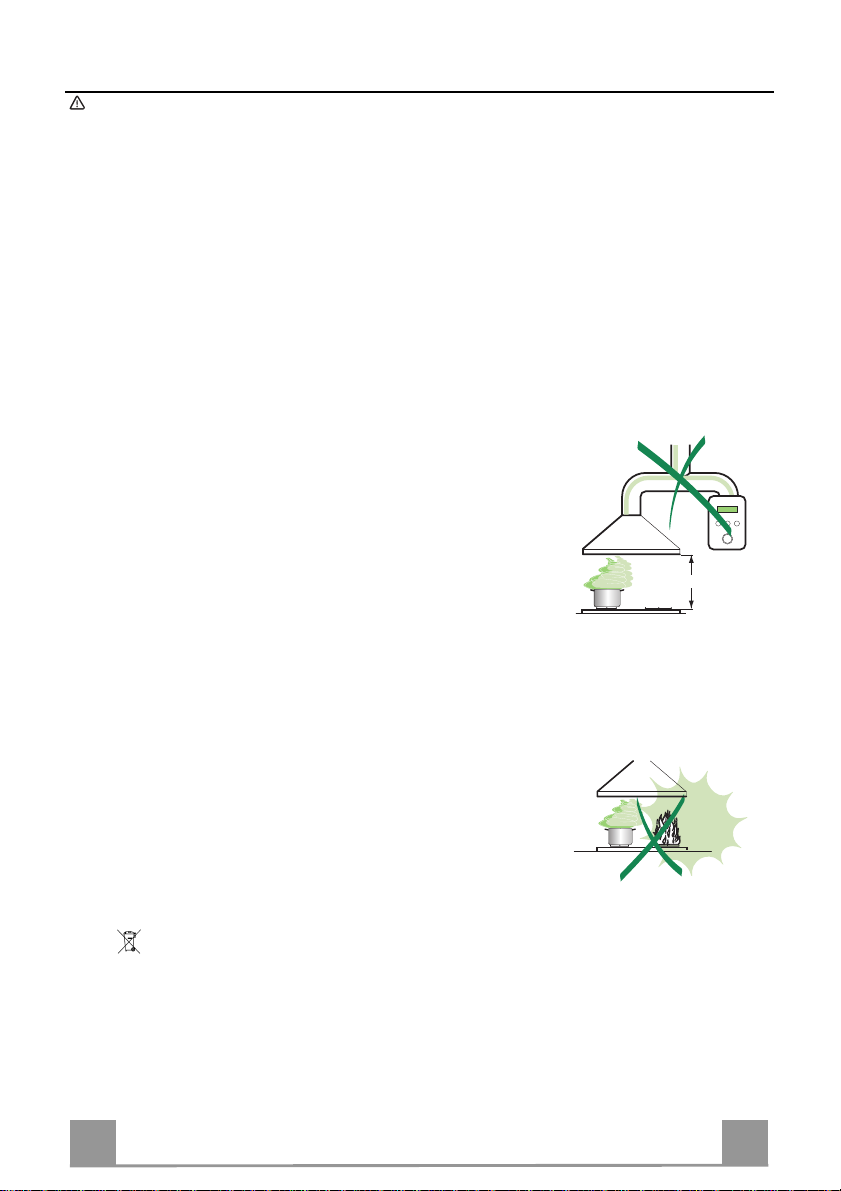
• The minimum safety distance between the cooker top and the extractor
hood is 650 mm (som e m od el s can be installed at a lower height, please refer to the paragraphs on working dimensions and installation).
• Check that the mains voltage corres ponds to that indicated on t he rating
plate fixed to the inside of the hood.
• For Class I appliances, check th at the domestic power supply guarantees
adequate earthing.
Connect the extractor t o the ex haus t flu e throu gh a pipe o f mi nimum diame-
ter 120 mm. The route of the flue must be as short as possible.
• Do not connect the ex tractor hood to exhaust ducts ca rrying combustion
fumes (boilers, fireplaces, etc.).
• If the ext ra ctor is used in conjunction with non-electrical appliances (e. g. g as
burning applia nces), a suffi cient degree of aeration must be guarantee d in
the room in order to prevent t he backfl ow of exha ust gas. T he kitch en must
have an opening communicating directly with the open air in order to
guarantee the entry of clean air.
USE
• The extractor hood has been designed exclusively for domestic use to eliminate kitchen smells.
• Never use the hood for purposes other than for which it has been designed.
• Never leave high naked fla me s un der the ho od wh en it is in oper at i on.
• Adjust th e fl am e i n te nsity to direct it onto the bottom of t he pan only, making
sure that it does not engulf the sides.
• Dee p fat fryers must b e continuously m onitored durin g use: overheate d oil
can burst into flames.
• Do not flambè under the range hood; risk of fire
• This ap pliance is not i ntended for use by persons (includi ng children) with
reduced physical , sensory or mental capabilitie s, or lack of ex perience and
knowledge, unless th ey have been g iven su pervi sion o r in structi on con cern ing use of the appliance by a person responsible for their safety.
• Child re n sh ould be supervised to ensure that they do not play with the appliance.
MAINTENANCE
• Switch off or unplug the appliance from the m ains supply before carrying out
any maintenance work.
• Clean and/or replace the Filters after the specified time period (Fire hazard).
• Clean the hood using a damp cloth and a neutral liquid detergent.
The symbol on the product or on its packaging indicates that this product may not be treated
as household waste. Instead it shall be handed over to the applicable collection point for the
recycling of electrical and electronic equipmen t. By ensuring this pr o duct is disposed of correctly,
you will help prevent potential negative consequences for the environment and human health,
which could otherwise be caused by inappropriate waste handling of this product. For more
detailed information about recycling of this product, please contact your local city office, your
household waste disposal service or the shop where you purchased the product.
3
3
Page 4

EN
CHARACTERISTICS
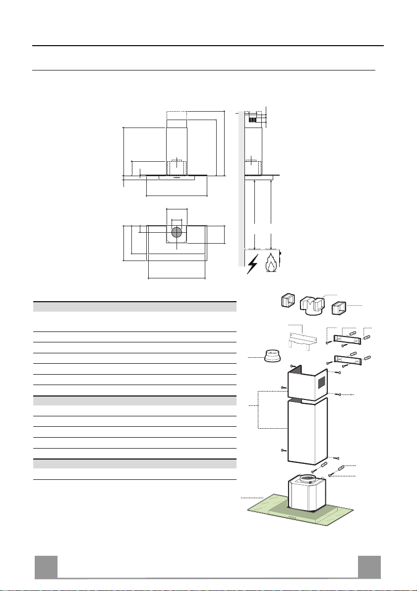
Dimensions
540
252
6
48
520
598 - 698 - 798 - 898
300
150
108
420
530
Min. 670
Max. 1000
260
Components
Ref. Q.ty Product Components
1 1 Hood Body, complete with: Controls, Light, Blower,
Filters
2 1 Telescopic Chimney comprising:
2.1 1 Upper Section
2.2 1 Lower Section
9 1 Reducer Flange ø 150-12 0 mm
14.1 2 Air Outlet Connection Extension
15 1 Air Outlet Connection
Ref. Q.ty Installation Components
7.2.1 2 Upper Chimney Section Fixing Brackets
7.3 1 Air Outlet Connection Su pport
11 6 Wall Plugs
12a 6 Screws 4,2 x 44,4
12c 6 Screws 2,9 x 9,5
Q.ty Documentation
1 Instruction Manual
126
Min.
500mm
4181
Min.
650mm
63
15
14.1
7.3
9
2.1
2
2.2
1
12a
7.2.1 11
12c
11
12a
4
4
Page 5
EN
INSTALLATION
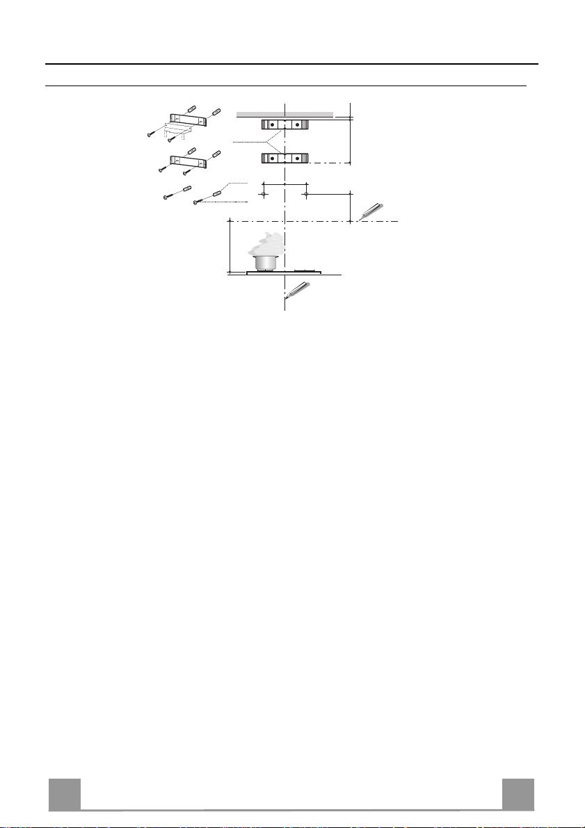
Wall drilling and bracket fixing
7.2.1
1÷2
X
11
12a
116
116
306
650 min.
Wall marking:
• Draw a vertical line on the supporting wall up to the ceiling, or as high as practical, at the
centre of the area in which the hood will be installed.
• Draw a horizontal line at 650 mm above the hob.
• Place bracket 7.2.1 on the wall as shown about 1-2 mm from the ceiling or upper limit align-
ing the centre (notch) with the vertical reference line.
• Mark the wall at the centres of the holes in the bracket.
• P l ace br acket 7.2.1 on the wall as shown at X mm below the first bracket (X = height of the
upper chimney section supplied), aligning the centre (notch) with the vertical line.
• Mark the wall at the centres of the holes in th e br acket.
• Mark a reference point as in dicated at 116 mm from the vertical reference li ne and 306 mm
above the horizontal reference l ine.
• Repeat this operation on the other side.
• Drill ø 8 mm holes at all the centre points marked.
• Insert the wall plugs 11 in the holes.
• Fix the lower bracket 7.2.1 using the 12a screws (4,2 x 44,4) supplied.
• Fix the upper bracket 7.2.1 and the air o utlet connection support 7.3 together using the 2
screws 12a (4,2 x 44,4) supplied.
• Insert the two screws 12a (4,2 x 44,4) supplied in the hood body fixing holes, leaving a gap
of 5-6 mm between the wall and the head of the screw.
5
5
Page 6
EN
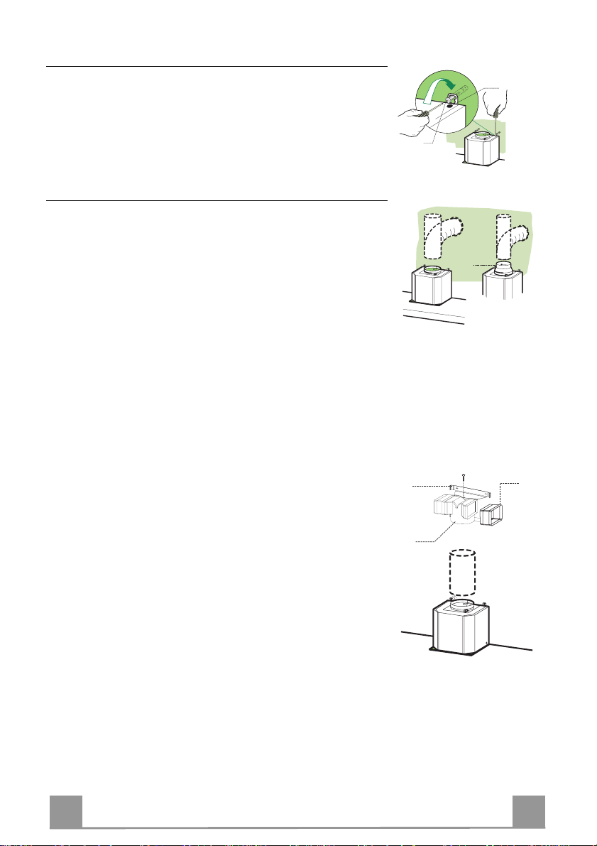
Mounting the hood body
9
ø 120ø 150
ø 150
15
14.1
7.3
• Before attaching the hood body, tighten the two screws Vr located on the hood body mounting points.
• Hook the hood body onto the screws 12a.
• Fully tighten the support screws 12a.
• Adjust the screws Vr to level the hood body.
Connections
DUCTED VERSION AIR EXHAUST SYSTEM
When installing the ducted version, connect the hood to the
chimney using either a flexible or rigid pipe ø 150 or 120 mm,
the choice of which is left to the installer.
• To install a ø 120 mm air exhaust connection, insert the reducer flange 9 on the hood body outlet.
• Fix the pipe in position using sufficient pipe clamps (not supplied).
• Remove any activated ch arcoal filters.
Vr
12a
RECIRCULATION VERSION AIR OUTLET
• Insert the connection exten sion pieces lat erally 14.1 in co nnection 15.
• Insert th e Connector 15 in to the Support bracket 7.3 and fix it
with a screw.
• Make sure that t he outlet of the extension pieces 14.1 is horizontally and vertically aligned with the chimney outlets.
• Connect the air outlet co nnection 15 to the hood body outlet
using either a flexible or rigid pipe ø 150 mm, the choice of
which is left to the installer.
• Ensure that the activated charcoal filters have been inserted.
6
6
Page 7
EN
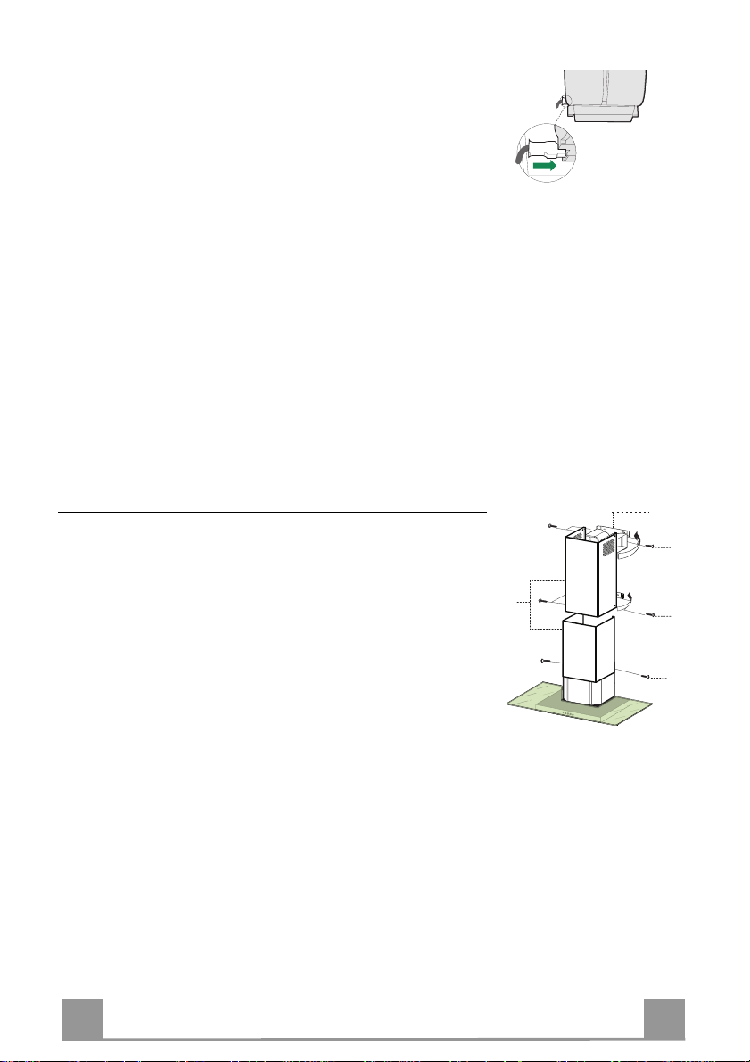
ELECTRICAL CONNECTION
12c
12c
12c
2.1
2.2
2
7.2.1
• Connect the hood to the mains through a two-pole switch having a contact gap of at least 3 mm.
• Re move the grease filters (see paragraph Maintenance) being
sure that the conn ector of the feeding cable is correctly inserted
in the socket placed on th e side of the fan.
Flue assembly
Upper exhaust flue
• Slightly widen the two sides of the upper flue and hook them
behind the brackets 7.2.1, making sure that they are well
seated.
• Secure the sides to the brackets by using the 4 screws 12c (2,9
x 9,5) supplied.
• Make sure that the outlet of the extension s pieces is aligned
with the chimney outlets.
Lower ex haust flue
• Slightly widen the two sides of the flue and hook them between the upper flue and t he wall, making sure that they are
well seated.
• Fix the lower part laterally to the hood body by using the 2
screws 12c (2,9 x 9,5) supplied.
7
7
Page 8
EN
USE
T1
T2
T3
L
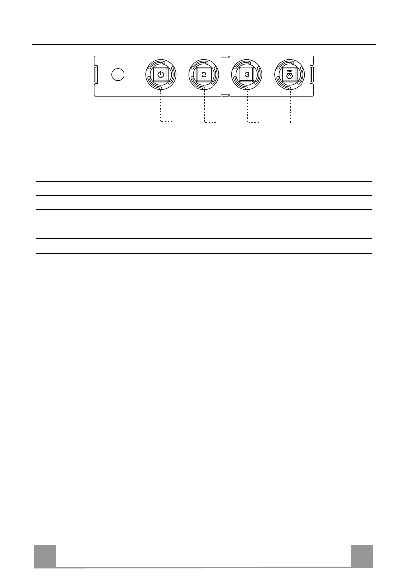
Control panel
BUTTON LED FUNCTIONS
T1 Speed On Turns the Motor on at Sp eed one.
Turns the Motor off.
T2 Speed On Turns the Motor on at Speed two.
T3 Speed Fixed When pressed briefly, turns the Motor on at Speed three.
L Light Turns the Lighting System on and off.
Warning: Button T1 turns the motor off, after first passing to speed one.
8
8
Page 9
EN
MAINTENANCE
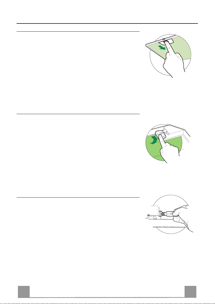
Grease filters
CLEANING META L SELF- SUPPO RTING GREASE FILTERS
• The filters must be cleaned every 2 months of operation, or
more frequently for particularly heavy usage, and can be
washed in a dishwasher.
• Remove the filters one at a time by pushing them towards the
back of the group and pulling down at the same time.
• Wash the filters, taking care not to bend them. Allow them to
dry before refitting.
• When refitting the filters, make sure that the handle is visible
on the outside.
Activated charcoal filter (Recirculation version)
REPLACING THE ACTIVATED CHARCOAL FILTE R
• The filter is not washable and cannot be regenerated, and must
be replaced approximately every 4 months of operation, or
more frequently for particularly heavy usage.
• Remove the metal grease filters.
• Remove the saturated activated carbon filter by releasing the
fixing hooks.
• Fit the new filter by hooking it into its seating.
• Refit the metal grease filters.
Lighting
LIGHT REPLACEMENT
40 W incandescent light.
• Remove the metal grease filters.
• Unscrew the bulbs and replace th em with new on es having the
same characteristics.
• Replace the metal grease filters.
9
9
Page 10
IT 110
CONSIGLI E SUGGERIMENTI
Questo libretto di istruzioni per l'uso è previsto per più versioni dell' appare
c
chio.
650 mm min.
É possibile che siano descritti singoli particolari della dotazione, che non riguardano il Vostro apparec c hio.
INSTALLAZIONE
• Il produttore declina qualsiasi responsabilità per danni dovuti ad installazione non
corretta o non confor me alle regole d ell’art e.
• La distanza minima di sicurezza tra il Piano di cottura e la Cappa deve essere di
650 mm, (alcuni modelli possono esser e installati ad un’alt ezza inferiore, fare riferimento ai paragrafi i ngo mbro e i nst al laz ione) .
• Verificare che la tensione di rete corrisponda a quella riportata nella targhetta
posta all’interno della Cappa.
• Pe r Appare cchi in C lasse I
sca un corretto sc ar ic o a ter ra.
• Collegare la Cappa all’uscita dell’aria aspirata con tubazione di diametro pari o
superiore a 120 mm. Il percorso della tubazione deve essere il più breve possibile.
• Non collegare la Cappa a condotti di scarico dei fumi prodotti da combustione
(caldaie, caminet ti , ec c.) .
• Nel caso in cui nella stanza vengano utilizzati sia la Cappa che apparecchi non
azionati da energia elettrica (ad esempio apparecchi utilizzatori di gas), si deve
provvedere ad una aerazione sufficiente dell’ambiente. Se la cucina ne fosse
sprovvista, praticare un’apertura che comunichi con l’esterno, per garantire il richiamo d’aria pulita.
USO
• La Cappa è stata progettata esclusivamente per uso domestico, per abbattere gli
odori della cucina.
• Non fare mai uso improprio del la Cap pa.
• Non lasciare fiamme liber e a for te i ntens it à sott o la Cappa i n funz i one.
• Regolare sempre le fiamme in modo da evitare una evidente fuoriuscita laterale
delle stesse ri spet t o al fondo dell e p entol e.
• Controllare le friggit r ici durant e l’ us o: l ’ol io surr isc aldat o potr ebb e inf iammar s i.
• Non preparare alimenti fl ambè sot to l a c appa da cuc i na; per ic olo d'i nc endi o.
• Que sto appare cchio n on deve esse re utiliz zato da person e (bambini inclusi) con
ridotte capacità psichiche, sensoriali o mentali, oppure da persone senza esperienza e conoscenza, a meno che non siano controllati o istruiti all’uso
dell’apparecchio da person e r esponsabili della loro sicurezza.
• I bambini devono essere supervisionati per assicurarsi che non giochino con
l’apparecchio.
MANUTENZIONE
• Prima di procedere a qualsiasi operazione di manutenzione, disinserire la Cappa
togliendo la spina elettrica o spegnendo l’interruttore generale.
• Effettuare una scrupolosa e tempestiva manutenzione dei Filtri secondo gli intervalli consigliati (Rischio di incendio).
• Per la pulizia delle su pe rfici d e lla C a ppa è suffi cie n te u tiliz za re u n pa nn o umido e
detersivo liqui do neutr o.
a
accertarsi ch e l’imp ianto e lettrico dome stico ga ranti-
Il simbolo sul prodotto o sulla confezione indica che il prodotto non deve essere considerato
come un nor m ale rifiuto domes ti c o , m a d eve essere portat o n el p unto di raccolta a ppropriato per
il ricicl aggi o di a ppar ec c hi atur e el et tri che e d el et tro nic he. P r ovv edendo a smaltire questo prodotto in modo appropriato, si contribuisce a evitare potenziali conseguenze negative per l’ambiente
e per la salute, che potrebbero derivare da uno smaltimento inadeguato del prodotto. Per informazioni più dettagliate sul riciclaggio di questo prodotto, contattare l’ufficio comunale, il servizio
locale di smaltimento rifiut i o il negozio in cui è stato acqu istat o il prodot to .
Page 11
IT 111
CARATTERISTICHE
Ingombro
540
252
6
48
520
598 - 698 - 798 - 898
300
150
108
420
530
Min. 670
Max. 1000
260
Componenti
Rif. Q.tà Componenti di Prodotto
1 1 Corpo Cappa completo di: Comandi, Luce, Gruppo
Ventilatore, Filtri
2 1 Camino Teles copico formato da:
2.1 1 Camino Superiore
2.2 1 Camino Inferiore
9 1 Flangia di Riduzione ø 150-120 mm
14.1 2 Prolunga Raccordo Uscita Aria
15 1 Raccordo Uscita Aria
Rif. Q.tà Componenti di Installazione
7.2.1 2 Staffe Fissaggi o Cami no Su periore
7.3 1 Staffa Sostegno Raccordo
11 6 Tasselli
12a 6 Viti 4,2 x 44,4
12c 6 Viti 2,9 x 9,5
Q.tà Documentazione
1 Libretto Istruzioni
126
Min.
500mm
4181
Min.
650mm
63
15
14.1
7.3
9
2.1
2
2.2
1
12a
7.2.1 11
12c
11
12a
Page 12

IT
112
INSTALLAZIONE
Foratura Parete e Fissaggio Staffe
7.2.1
1÷2
X
11
12a
116
116
306
650 min.
Tracciare sulla Parete:
• una linea Verticale fino al soffitto o al limite superiore, al centro della zona prevista per il
montaggio della Cappa;
• una linea Orizzon tale a: 650 mm min. sopra il Piano di Cottura.
• Appoggiare come indicat o l a Staffa 7.2.1 a 1-2 mm dal soffitto o dal limite superiore, allineando il suo centro (intagli) sulla linea Verticale di riferimento.
• Segnare i centri dei Fori della Staffa.
• Appoggiare come indicato la Staffa 7.2.1 a X mm sotto la p rima staffa (X = altezza Ca mino
Superiore in dotazione), allineando il suo centro (intagli) sulla linea Verticale di riferimento.
• Segnare i centri dei Fori della Staffa.
• Segnare come indicato, un punto di riferimento a 116 mm dalla linea Verticale di riferimento, e 306 mm sopra la linea Orizzontale di riferimento.
• Ripetere questa operazione dalla parte opposta.
• Forare ø 8 mm i punti segnati.
• Inserire i tasselli 11 nei fori.
• Fissare la Staffa inferiore 7.2.1 utilizzando le Viti 12a (4,2 x 44,4 ) in dotazione.
• Fissare insieme la Staffa superiore 7.2.1 e la Staffa sostegno racc ordo 7.3 utilizzando le 2
viti 12a (4,2 x 44,4) in dotazione.
• Avvitare 2 Viti 12a (4,2 x 44,4) in dotazione nei fori per il fissaggio del corpo Cappa, lasciando uno spazio di 5-6 mm fra la parete e la testa della vite.
Page 13

IT 113
Montaggio Corpo Cappa
9
ø 120ø 150
ø 150
15
14.1
7.3
• Prima di agganciare il Corpo Cappa, serrare le 2 Viti Vr situate
sui punti di aggancio del Corpo Cappa.
• Agganciare il Corpo Cappa alle Viti 12a.
• Serrare definitivamente le Viti 12a di supporto.
• Agire sulle Viti Vr per livellare il Corpo Cappa.
Connessioni
USCITA ARIA VERSIONE ASPIRANTE
Per installazione in Versione Aspirante collegare la Cappa alla
tubazione di uscita per mezzo di un tubo rigido o flessibile di
ø150 o 120 mm, la cui scelta è lasciata all'installatore.
• Per collegamento con tubo ø120 mm, inserire la Flangia di riduzione 9 sull’Uscita del Corpo Cappa.
• Fissare il tubo con adeguate fascette stringitubo. Il materiale
occorrente non è in dotazione.
• Togliere eventuali Filtri Antiodore al Carbone attivo.
Vr
12a
USCITA ARIA VERSIONE FILTRANTE
• Inserire lateralmente le Prolunghe Racco rdo 14.1 sul Raccordo
15.
• Inserire il Racco rdo 15 nella Staffa di Sostegno 7.3 fissandolo
con una Vite.
• Assicurarsi che l’uscita delle Prolunghe Raccordo 14.1 risulti
in corrispondenza delle bocchette del Camino sia in orizzontale
che in verticale.
• Co llegare il Raccordo 15 all’Uscita del Corpo Cappa per mezzo di un tubo rigido o flessibile di ø150 mm, la cui scelta è lasciata all'installatore.
• Assicurarsi della presenza del Filtro Antiodore al Carbone attivo.
Page 14

IT 114
CONNESSIONE ELETTRICA
12c
12c
12c
2.1
2.2
2
7.2.1
• Collegare la Cappa all’Alimentazione di Rete interponendo un
Interruttore bipolare con apertura dei contatti di almeno 3 mm.
• Rimuovere i Filtri antigrasso (vedi par. “Manutenzione”) e assicurarsi che il connettore del Cavo di alimentazione sia correttamente inserito nella presa dell’Aspiratore
Montaggio Camino
Camino superiore
• Allargare leggermente le due falde laterali, agganciarle dietro
le Staffe 7.2.1 e richiuderle fino a battuta.
• Fissare lateralmente alle Staffe con 4 Viti 12c (2,9 x 9,5) in
dotazione.
• Assicurarsi che l’uscita delle Prolunghe Raccordo risulti in corrispondenza delle bocc hette de l C am i no.
Camino inferiore
• Allargare leggermente le due falde laterali del Camino, agganciarle tra il Camino superiore e la parete e richiuderle fino a
battuta.
• Fissare lateralmente la parte inferiore al Corpo Cappa, con 2
Viti 12c (2,9 x 9,5) in dotazione.
Page 15

IT 115
USO
T1
T2
T3
L
Quadro comandi
TASTO LED FUNZIONI
T1 Velocità Acceso Accende il Motore alla Prima velocità.
Spegne il Motore.
T2 Velocità Acceso Accende il Motore alla Seconda velocità.
T3 Velocità Fisso Premuto brevemente Accende il Motore alla Terza velocità.
L Luce Accende e spegne l’Impianto di Illuminazione.
Attenzione: Il tasto T1 spegne il motore passando sempre per la prima velocità.
Page 16

IT 116
MANUTENZIONE
Filtri antigrasso
PULIZIA FILTRI ANTIGRASSO METALLICI AUTOPORTANTI
• Sono lavabili anche in lavastoviglie, e necessitano di essere
lavati ogni 2 mesi circa di utilizzo o più frequentemente, per un
uso particolarmente intenso.
• Togliere i Filtri uno alla volta, spingendoli verso la parte posteriore del gruppo e tir ando contemporaneamente verso il basso.
• Lavare i Filtri evitando di piegarli, e lasciarli asciugare prima
di rimontarli.
• Rimontarli facendo attenzione a mantenere la maniglia verso la
parte visibile esterna.
Filtro antiodore (Versione Filtrante)
SOSTITUZIONE FILTRO ANTIODORE AL CARBONE ATTIVO
• Non è lavabile e non è rigenerabile, va sostituito almeno ogni 4
mesi o più frequentemente, per un uso particolarmente intenso.
• Togliere i Filtri antigrasso metallici.
• Rimuovere il Filtro antiodore al Carbone attivo saturo, agendo
sugli appositi agganci.
• Montare il nuovo Filtro agganciandolo nella sua sede.
• Rimontare i Filtri antigrasso metallici.
Illuminazione
SOSTITUZIONE LAMPADE
Lampade a incandescenz a da 40 W
• Togliere i Filtri antigrasso metallici.
• Svitare le Lampade e sostituirle con nuove di uguali caratteristiche.
• Rimontare i Filtri antigrasso metallici.
Page 17

FR 117
CONSEILS ET SUGGESTIONS
650 mm min.
La présente notice d'emploi vaut pour plusieurs versions de l'appareil. Elle peut conte-
nir des descriptions d'accessoir es ne fi gurant pas dan s votr e apparei l.
INSTALLATION
• Le fabricant décline toute responsabilité en cas de dommage dû à un e in st alla tion non
correcte ou non conforme aux règles de l ’ art.
• La distance minimale de sécurité entre le plan de cuisson et la hotte doit être de 650
mm au moins (certains modèles peuvent être installés à une hauteur inférieure : se reporter aux paragraphes « Encombrem ent » et « Instal lati on »).
• Vérifier que la tension du secteur correspond à la valeur qui figure sur la plaquette
apposée à l’intérieur de la hotte.
• Pour les Appareils appartenant à la Ière Classe, veiller à ce que la mise à la terre de
l’installation électrique domestique ait été effectuée conformément aux normes en vigueur.
• Connecter la hotte à la sort ie d’air aspiré à l’ aide d’une tuyauterie d’un diamètre égal ou
supérieur à 120 mm. Le parcours de la tuyaut eri e doit être le plus court possibl e.
• Ne pas connecter la hotte à des conduites d’évacuation de fumées issues d’une combustion tel que (Chaudière, chemi née, et c…).
• Si vous utilisez des appareils qui ne fonctionnent pas à l’électricité dans la pièce ou est
installée la hotte (par exemple: des appareils fonctionnant au gaz), vous devez prévoir
une aération suffisante du milieu. Si la cuisine en est dépourvue, pratiquez une ouverture qui communique avec l’ext érieur pour garant ir l’infil trati on de l’ai r pur.
UTILISATION
• La hotte a été conçue exclusivement pour l’usage domestique, dans le but d’éliminer
les odeurs de la cuisine.
• Ne jamais utiliser abusivement la hotte.
• Ne pas laisser les flammes libres à forte intensité quand la hotte est en service.
• Toujours régler les flammes de manière à éviter toute sortie latérale de ces dernières
par rapport au fond des marmites.
• Contrôler les friteuses lors de l’utilisati on car l’huile sur chauff ée pourrai t s’ enfl ammer.
• Ne pas préparer d’aliments flambés sous la hotte de cuisi ne : risque d’ incendi e
• Cet appareil ne doit pas être utilisé par des personnes (y compris les enfants) ayant
des capacités psychiques, sensorielles ou mentales réduites, ni par des personnes
n’ayant pas l’expérience et la connaissance de ce type d’appareils, à moins d'être so us
le contrôle et la formation de personn es respo nsables de l eur sécuri té.
• Les enfants doivent être surveillés pour s'assurer qu'ils ne jouent pas avec l'appareil.
ENTRETIEN
• Avant de procéder à toute opération d’entretien, ret irer la hotte en retirant la fiche ou en
actionnant l’interrupteur général.
• Effectuer un entretien scrupuleux et en temps dû des Filtres, à la cadence conseillée
(Risque d’incendie).
• Pour le nettoyage des surfaces de la hotte, il suffit d’utiliser un chiffon humide et détersif liquide neutr e.
Le symbole sur le produit ou son emballage indique que ce produit ne peut être traité comme
déchet ménager. Il doit plutôt être remis au point de ramassage concerné, se chargeant du recyclage du matériel électrique et électronique. En vous assurant que ce produit est éliminé correctement, vous favorisez la prévention des conséquences négatives pour l’environnement et la santé
humaine qui, sinon, seraient le résultat d’un traitement inapproprié des déchets de ce produit. Pour
obtenir plus de détails sur le recyclage de ce produit, veuillez prendre contact avec le bureau municipal de votre région, votre service d’élimination des déchets ménagers ou le magasin où vous avez
acheté le produit.
Page 18

FR 118
CARACTERISTIQUES
Encombrement
540
252
6
48
520
598 - 698 - 798 - 898
300
150
108
420
530
Min. 670
Max. 1000
260
Composants
Réf. Q.té Composants de Produit
1 1 Corps Hotte équ ipé de:Command es, Lumière, Groupe
Ventilateur,Filtres
2 1 Cheminée Télescopique formée de :
2.1 1 Cheminée Supérieure
2.2 1 Cheminée Inférieure
9 1 Flasque de Réduction ø 150-120 mm
14.1 2 Rallonge Raccord Sortie Air
15 1 Raccord Sortie Air
Réf. Q.té Composants pour l ’installation
7.2.1 2 Brides Fixation Cheminée Supérieure
7.3 1 Bride Support Raccord
11 6 Chevilles
12a 6 Vis 4,2 x 44,4
12c 6 Vis 2,9 x 9,5
Q.té Documentation
1 Manuel d’instructions
126
Min.
500mm
4181
Min.
650mm
63
15
14.1
7.3
9
2.1
2
2.2
1
12a
7.2.1 11
12c
11
12a
Page 19

FR 119
INSTALLATION
Perçage Paroi et Fixation Brides
7.2.1
1÷2
X
11
12a
116
116
306
650 min.
Tracer sur la paroi:
• une ligne verticale allant jusqu’au plafond ou à la limite supérieure, au centre de la zone
prévue pour le montage de la hotte;
• une ligne horizontale à 650 mm min. au-dessus du plan de cuisson.
• Poser comme indiqué une brid e 7.2.1 sur la paroi à 1-2 mm du plafond ou de la limite supérieure, en alignant son centre (découpes) sur la ligne verticale de repère.
• Marquer les centres des trous rainurés de la bride.
• Poser comme indiqué la bride 7.2.1 à X mm sous la première bride (X = hauteur cheminée
supérieure fournie), en al ignant son centre (découpes) sur la ligne verticale de repère.
• Marquer les centres des trous rainurés de la bride.
• Marquer comme indiqué, un point de référence à 116 mm de la ligne verticale de repère, et
306 mm au-dessus de la ligne horizontale de repère.
• Répéter cette opération sur le côté opposé.
• Percer de ø 8 mm tous les points marqués.
• Insérer les chevilles 11 dans les trous.
• Fixer la bride inférieure 7.2.1 en utilisant les vis 12a (4,2 x 44,4) fournies.
• Fixer ensemble la bride supérieure 7.2.1 et le support 7.3 en utilisant les vis 12a (4,2 x 44,4)
fournies.
• Visser les 2 vis 12a (4,2 x 44,4) fournies dans les trous de fixation du corps hotte, en laissant
un espace de 5-6 mm entre le mur et la têt e de la vis.
Page 20

FR 220
Montage Corps Hotte
9
ø 120ø 150
ø 150
15
14.1
7.3
• Avant d’accrocher le corps hotte, serrer les deux vis Vr situées
sur les points d’accrochage du corps hotte.
• Accrocher le corps hotte aux vis 12a prévues à cet effet.
• Serrer définitivement les vis 12a de support.
• Agir sur les vis Vr pour niveler le corps hotte.
Branchements
SORTIE AIR VERSION ASPIRANTE
En cas d’installation en version aspirante, brancher la hotte à la
tuyauterie de sortie via un tube rigide ou flexible de ø 150 ou 120
mm, au choix de l’installateur.
• En cas de branchement avec un tu be de ø120 mm, insérer le
flasque de réduction 9 sur la sortie du corps de la hotte.
• Fixer le tube par des colliers appropriés. Le matériau nécessaire n’est pas fourni.
• Retirer les éventuels filtres anti-odeur au charbon actif.
Vr
12a
SORTIE AIR VERSION FILTRANTE
• Insérer latéralement les rallonges raccord 14.1 sur le raccord
15.
• Placer le raccord 15 dans l’étrier de soutien 7.3 en le fixant
avec une vis.
• S’assurer que la sortie des rallonges racco rd 14.1 se trouve au
niveau des bouches de la cheminée aussi bien en horizontal
qu’en vertical.
• Bran cher le raccord 15 à la sortie du corps de la hotte avec un
tube rigide ou flexible de ø 150 mm, selon le choix de
l’installateur.
• S’assurer de la présence des filtres anti-odeur au charbon actif.
Page 21

FR 221
BRANCHEMENT ELECTRIQUE
12c
12c
12c
2.1
2.2
2
7.2.1
• Brancher la hotte sur le secteur en interpo sant un interrupteur
bipolaire avec ouvertu re des contacts d’au moins 3 mm.
• Enlever les filtres à graisse (voir § "Entretien") et s'assurer que
le connecteur du câbl e d'al imentati on so it bien bran ché dan s la
prise du diffuseur.
Montage Cheminée
Cheminée supérieure
• Elargir légèrement les deux bords latériaux, et les accrocher
derrières les brides 7.2.1 ; refermer
jusqu’à la butée.
• Fixer latéralement aux brides à l’aide des 4 vis
12c fournies.
• S’assurer que la sortie des rallonges raccord se trouve au niveau des bouches de la cheminée.
Cheminée inférieure
• Elargir légèrement les deux bords latériaux de la Cheminée et
les accrocher entre la Cheminée sup éri eure et la paroi; refermer
jusqu’à la butée.
• Fixer latéralement la partie inférieure au corps
hotte, à l’aide des deux 2 vis 12c fournies.
Page 22

FR 222
UTILISATION
T1
T2
T3
L
Tableau des commandes
TOUCHE VOYANT FONCTIONS
T1 Vitesse Allumé Démarre le moteur en première vitesse.
Coupe le moteur.
T2 Vitesse Allumé Démarre le moteur en deuxième vitesse.
T3 Vitesse Fixe Appuyée brièvement, démarre le moteur en troisième vitesse.
L Lumière Branche et débranche l’éclai rage.
Attention : La touche T1 coupe le moteur en passant toujours par la première vitesse.
Page 23

FR 223
ENTRETIEN
Filtres anti-graisse
NETTOYAGE FILTRE S ANTI -GRAISS E METALLI QUES AUTOPO RTEUR S
• Lavables au lave-vaisselle, ils doivent être lavés environ tous
les 2 mois d’emploi ou plus fréquemment en cas d’emploi particulièrement intense.
• Retirer les filtres l’un aprés l’autre, en les poussant vers la partie arrière du groupe et en tirant simultanément vers le bas.
• Laver les filtres en évitant de les plier et les laisser sécher avant
de les remonter.
• Remonter les filtres en veillant à ce que la poignée reste vers la
partie visible externe
Filtre anti-odeur (Version filtrante)
REMPLACEMENT FILTRE AU CHARBON ACTIF
• Ni lavable, ni régénérable, le remplacer au moins tous les 4
mois d’emploi ou plus fréquemment en cas d’emploi particulièrement intense.
• Retirer les filtres anti-graisse métalliques.
• Retirer le filtre anti-odeur au charbon actif colmaté, en agissant
sur les crochets prévus à cet effet.
• Monter le nouveau filtre anti-odeur au charbon actif.
• Remonter les filtres anti-graisse métalliques.
Eclairage
REMPLACEMENT LAMPES
Lampes à incandescence de 40 W
• Retirer les filtres anti-graisse métalliques.
• Dévisser les l ampes et les remplacer par de nou velles avec les
mêmes caractéristiques.
• Remonter les filtres anti-graisse métalliques.
Page 24

DE 224
EMPFEHLUNGEN UND HINWEISE
650 mm min.
Diese Gebrauchsanleitung gilt für mehrere Geräte-Ausführungen. Es ist möglich, dass
einzelne Ausstattungsmerkmale beschrieben sind, die nicht auf Ihr Gerät zutreffen.
MONTAGE
• Der Hersteller haftet nicht für Schäden, die auf eine fehlerhafte und unsachgemäße Montage zurückzuführen sind.
• Der minimale Sicherheitsabstand zwischen Kochmulde und Haube muss 650 mm betragen (einige Modelle können an einer geri ngeren Höhe i nstalli ert werden, bezi ehen Si e sich
dazu auf den Absatz Raumbedarf und Installation).
• Prüfen, ob die Netzspannung mit dem Wert auf dem im Haubeninneren angebrachten Schild übereinstimmt.
• Bei Geräten der Klasse I ist sicherzustellen, dass die elektrische Anlage des Wohnha uses
über eine vorschriftsmäßige Erdung verfügt.
• Das Anschlussrohr der Haube zur Luftaustrittsöffnung muss einen Durchmesser von 120
mm oder darüber aufweisen. Der Rohrverlauf muss so kurz wie möglich sein.
• Die Haube darf an keine Entlüftungsschächte angeschlossen werden, in die Verbrennungsgase (Heizkessel, Kamine usw.) geleitet werden.
• Werden im Raum außer der Dunstabzugshaube andere, nicht elektrisch betriebene (z.B.
gasbetriebene) Geräte verwendet, muss für eine ausreichende Belüftung gesorgt werden.
Sollte die Küche diesbezüglich nicht entsprechen, ist an einer Aussenwand eine Öffnung
anzubringen, die Frischluftzufuhr gewährleistet.
BEDIENUNG
• Die Dunstabzugshaube ist ausschließlich zum Einsatz im privaten Haushalt und zur
Beseitigung von Küchengerüchen vorgesehen.
• Unsachgemäßer Einsatz der Haube ist zu unterlassen.
• Große Flammen bei eingeschalteter Haube niemals unbedeckt lassen.
Achtung! Große Flammen be i eing esc haltet e r Haube niema ls un bedeck t lasse n.
• Die Intensivität der Flamme ist so zu regulieren, dass sie den Topfboden nicht überragt.
Achtung! Frittiergeräte müssen während des Gebrauchs stets beaufsichtigt wer-
den: Überhitztes Öl kann sich entzünden.
• Frittiergeräte müssen während des Gebrauchs stets beaufsichtigt werden: überhitztes Öl
kann sich entzünden.
• Keine flambierten Speisen unter der Abzugshaube zubereiten: Brandgef ahr.
• Dieses Gerät darf nicht von Personen, auch Kindern, mit verminderten psychischen, sensorischen und geistigern Fähigkeiten, oder von Personen ohne Erfahrung und K ennt nisse
benutzt werden, sofern sie nicht von für ihre Sicherheit verantwortlichen Personen beaufsichtigt und beim Gebrauch des Geräts angeleitet werden.
• Kinder dürfen sich nicht unbeaufsichtigt in der Nähe des Geräts aufhalten und auf keinen
Fall mit dem Gerät spielen.
WARTUNG
• Bevor Wartungsarbeiten durchgeführt werden, muss die Stromzufuhr zur Haube unterbrochen werden, indem der Stecker gezogen oder der Hauptschalter abgeschaltet wird.
• Bei der Filterwartung müssen die vom Hersteller empfohlenen Zeiträume zum Austauschen
der Filter genauestens eingehalten werden (Brandgefahr).
• Zur Reinigung der Haubenflächen Wir empfehlen ein feuchtes Tuch und ein mildes Flüssigreinigungsmittel.
• Bitte keine Reinigungsmittel mit Scheuermittel verwenden. Die Oberfläche wird damit
verkratzt.
Das Symbol auf dem Produkt oder seiner Verpackung weist darauf hin, dass dieses Produkt nich t als
normaler Haushaltsabfall zu behandeln ist, sondern an einem Samme lpunkt für das Recycling vo n elektrischen und elektronischen Geräten abgegeben werden muss. Durch Ihren Beitrag zum korrekten Entsorgen
dieses Produkts schützen Sie die Umwelt und die Gesundheit Ihrer Mitmenschen. Umwelt und Gesundheit
werden durch falsches Entsorgen gefährdet. Weitere Informationen über das Recycling dieses Produkts
erhalten Sie von Ihrem Rathaus, Ihrer Müllabfuhr oder dem Geschäft, in dem Sie das Produkt gekauft haben.
Page 25

DE 225
CHARAKTERISTIKEN
Platzbedarf
540
252
6
48
520
598 - 698 - 798 - 898
300
150
108
420
530
Min. 670
Komponenten
Pos. St. Produktkomponenten
1 1 Haubenkörper mit Schaltern, Beleuchtung, Gebläse-
gruppe, Filter
2 1 Teleskopkamin bestehend aus:
2.1 1 oberer Kaminteil
2.2 1 unterer Kaminteil
9 1 Reduzierflansch ø 150-120 mm
14.1 2 Verlängerung Luftaustritt-Anschlussstück
15 1 Luftaustritt-Anschlussstück
Pos. St. Montagekomponenten
7.2.1 2 Befestigungsbügel oberer Kaminteil
7.3 1 Bügel für Anschlusshalter
11 6 Dübel
12a 6 Schrauben 4,2 x 44,4
12c 6 Schrauben 2,9 x 9,5
St. Dokumentation
1 Bedienungsanleitung
Max. 1000
260
126
Min.
500mm
4181
Min.
650mm
63
15
14.1
7.3
9
2.1
2
2.2
1
12a
7.2.1 11
12c
11
12a
Page 26

DE 226
MONTAGE
Bohren der Befestigungslöcher und Fixieren der Befestigungsbügel
7.2.1
1÷2
X
11
12a
116
116
306
650 min.
Achtung: Bitte beachten Sie bei der Montage das Gewicht der kompletten Haube. Die Tragfä-
higkeit der Decke oder alternativ der Trägerplatte für diese Zugbelastung muss vor der Montage geprüft und gegebenenfalls durch die Anbringung von geeigneten Befestigungs- oder
Stabilisierungselementen hergestellt werden. Kann eine hinreichende Tragfähigkeit nicht sichergestellt werden, ist von einer Montage abzusehen.
Nachstehende Linien an die Wand zeichnen:
• eine vertikale Linie bis zur Decke oder oberen Begrenzung, und zwar in der Mitte des Bereiches, in dem die Haube montiert werden soll;
• eine horizontale Linie: mit einem minimalen Abstand von 650 mm zur Kochfläche.
• Einen Bügel 7.2.1 zirka 1-2 mm unter der Decke oder oberen Begrenzung an die Wand legen und seinen Mittelpunkt (Einschnitte) auf die vertikale Bezugslinie ausrichten.
• Die Mitte der beiden Bügellöcher an der Wand markieren.
• Den zweiten Bügel 7.2.1 an die Wand legen, wobei ein Abstand X mm vom oberen Bügel
einzuhalten ist (X = Höhe des jeweiligen oberen Kaminteils); den Mittelpunkt (Einschnitte)
auf die vertikale Bezugslinie ausrichten.
• Die Mitte der Bügellöcher an der Wand markieren.
• Wie beschrieben einen Bezugspunkt 116 mm von der vertikalen Bezugslinie und 306 mm
oberhalb der horizontalen Bezugslinie kennzeichnen.
• Gleichermaßen an der gegenüberliegenden Seite vorgehen.
• Mit einem Bohrer ø 8 mm die markierten Punkte bohren.
• Die Dübel 11 in die Bohrungen einfügen.
• Den unteren Bügel mit den mitgelieferten Schrauben 12a (4,2 x 44,4) fixieren.
• Den Bügel für Anschlusshalter mit den 2 mitgelieferten Schrauben 12a (4,2 x 44,4) auf den
oberen Bügel 7.2.1 befestigen.
• 2 der mitgelieferten Schrauben 12a (4,2 x 44,4) bei den Befestigungslöchern des Hauben-
körpers einschrauben, wobei zwischen Wand und Schraubenkopf ein Freiraum von 5-6 mm
zu belassen ist.
Page 27

DE 227
Montage des Haubenkörpers
9
ø 120ø 150
ø 150
15
14.1
7.3
• Bevor der Haubenkörper eingehakt wird, die 2 Schrauben Vr
bei den Haubenkörper-Anhakpunkten festziehen.
• Den Haubenkörper bei den Sc hraube n 12a einhängen.
• Die Halteschrauben 12a definitiv festziehen.
• Den Haubenkörper mit Hilfe der Schrauben Vr ausrichten.
Anschluss der Abluftversion
Bei Abluftbetrieb kann die Haube vom Installateur wahlweise
mittels Rohr oder Schlauch (ø 150 oder 120 mm) an die Außenrohrleitung angeschlossen werden.
• Bei Verwendung eines Anschlussrohres ø 120 den Reduzierflansch 9 am Haubenaustritt anbringen.
• Das Rohr mit geeigneten Rohrschellen fixieren. Das hierzu
erforderliche Material wird nicht mitgeliefert.
• Eventuell vorhandene Aktivkohlefilter entnehmen.
Achtung! Alle Querschnittänderungen oder Richtu ngsän-
derungen de s Abluf tkan als red uzieren die Lei stung der Haube.
Vr
12a
Anschluss der Umluftversion
• Die Verl ängeru ngen 14.1 beim Anschluss 15 seitlich einfügen.
• Den Anschluss 15 am Haltebügel 7.3 einsetzen und mit einer
Schraube fixieren.
• Überpr üfen, ob die V erlängerungen 14.1 mit den entsprechenden Kaminstutzen sowohl horizontal wie auch vertikal übereinstimmen.
• Vom Installateur wahlweise mittels Rohr oder Schlauch (ø 150
mm), den Anschluss 15 am Haubenaustritt anbringen.
• Kontrollieren, ob der Aktivkohle-Geruchsfilter montiert ist.
Page 28

DE 228
Elektroanschluss
12c
12c
12c
2.1
2.2
2
7.2.1
Vor der Installation die Netzspannung durch herausdrehen der
Sicherung oder ausschalten des Hauptschalters s tromlos machen.
• Bei Anschluss der Haube an das Stromnetz muss ein
zweipoliger Schalter mit einem Öffnungsweg von
mindestens 3 mm zwischengeschaltet werden.
• Entfernen Sie die Fettfilter (s. Abschnitt „Wartung“) und
versichern Sie sich, daß die Kabel verbindung in die Steckdose des Gebläses einwandfrei eingesteckt wird.
Achtung: Das Gerät nur an die Netzspannung die im Typen-
schild angegeben ist anschließen.
Kaminmontage
Oberer Kaminteil
• Die beiden seitlichen Schenkel leicht auseinanderbiegen, hinter
den Bügeln 7.2.1 einhängen und bis zum Anschlag wieder
schließen.
• Bei den Bügeln 7.2.1 mit Hilfe der 4 mitgelieferten Schrauben
12c fixieren.
• Überprüfen, ob die Verlängerungen mit den entsprechenden
Kaminstutzen überein stimmen.
Unterer Kaminteil
• Die beiden seitlichen Schenkel des Kaminteils leicht auseinander biegen, zwischen dem oberen Kaminteil und der Wand
einhängen und bis zum Anschlag wieder schließen.
• Den unteren Teil seitlich am Haubenkörper mit 2 der mitgelieferten Schrauben 12c fixieren.
Page 29

DE 229
BEDIENUNG
T1
T2
T3
L
Schalttafel
TASTE LED FUNKTIONEN
T1 Betriebsgeschwindigkeit Eingeschaltet Schaltet den Motor bei der ersten
Betriebsgeschwindigkeit ein.
Stellt den Motor ab.
T2 Betriebsgeschwindigkeit Eingeschaltet Schaltet den Motor bei der zweiten
Betriebsgeschwindigkeit ein.
T3 Betriebsgeschwindigkeit Bleibend Schaltet den Motor bei der dritten
Betriebsgeschwindigkeit ein.
L Licht Schaltet die Beleuchtung ein und aus.
Achtung: Mit der Taste T1 wird von der ersten Betriebsgeschwindigkeit aus der Motor
abgestellt.
Page 30

DE 330
WARTUNG
Fettfilter
SELBSTTRAGENDER METALLFETTFILTER REINIGUNG
• Sie müssen nach 2-monatigem Betrieb bzw. bei starkem Einsatz auch häufiger gereinigt werden, was im Geschirrspüler
möglich ist.
• Die Filter nacheinander aushaken, indem sie auf die Rückseite
der Gruppe geschoben und gleichzeitig nach unten gezogen
werden.
• Die Filter reinigen (darauf achten, sie nicht zu verbiegen) und
vor der Remontage trocknen lassen.
• Bei der Remontage ist darauf zu achten, dass sich der Griff auf
der sichtbaren Außenseite befindet.
Geruchsfilter (Umluftversion)
AUSTAUSCHEN DER AKTIVKOHLE FILTER
• Dieser Filter kann weder gewaschen noch wiederverwendet
werden und ist alle 4 Betriebsmonate bzw. bei starkem Einsatz
auch häufiger auszutauschen.
• Die Metallfettfilter entfernen.
• Den gesättigten Aktivkohle-Geruchsfilter aushaken.
• Den neuen Filter in seinem Sitz einhaken.
• Die Metallfettfilter wieder montieren.
Beleuchtung
AUSWECHSELN DER LAMPEN
Glühlampen 40W
• Die Metallfettfilter entfernen.
• Die Lampen ausschraub en und durch gleichwertige ersetzen.
• Die Metallfettfilter wieder montieren.
Page 31

TR 331
TAVSIYELER VE ÖNERILER
Bu kullanma talimatι birden fazla cihaz modeli i
çin
geçerlidir.
650 mm min.
Cihazιnιza uymayan bazι donanιm özellikleri tarif edilmiş olabilir.
MONTAJ
• Yalnιş veya eksik montajdan doğan herhangi bir z ararιn sorumluluğu
üreticiye ait değildir.
• Davlumbaz ile pişirici cihazιn ocak kιsmι arasιndaki minimum güvenlik
mesafesi 650 mm.dir (bazı modeller daha alçak s eviyede bi r yüks ekliğe kurulabilir, hacim ve kurulum ile ilgili paragraflara bakı nız).
• Besleme voltajιnιn, davlumbaz içerisine yerleştirilen bilgi etiketinde
belirtilenle aynι olup olmadιğιnι kontrol edin.
• Sιnιf I elektrikli aletleri için, güç kaynağιnιn yeterli topraklamayι
sağlayιp sağlamadιğιnι kontrol edin. Minimum 120 mm çapιnda bir
boru yoluyla davlumbazι çιkιş bacasιna bağlayιn. Baca bağlantιsι
mümkün oldu- ğunca kιsa olmalιdιr.
• Davlumbaz borusunu yanιcι duman taşιyan baca deliğine (buhar
kazanι, şömine, vb.) bağlamayιn.
• Davlumbazιn elektrikle çalιşmayan aletlerle (örneğin; gazlι cihazlar)
bağιntιlι olarak kullanιlmamasι halinde çιkιş gazιnιn geri tepmesini
önlemek amacιyla odada yeterl i bir havalandιrma sağlanmalιdιr. Temiz hava girişini temin etmek için mutfakta doğrudan dιşarιya açιlan
bir açιklιk bulunmalιdιr.
KULLANIM
• Davlumbaz mutfaktaki kokularιn emilmesi amacιyla evlerde kullanιm
için tasarlanmιştιr.Ticari ve endüstriyel amaçlar için kullanmayιnιz.
• Davlumbazι tasarlandιğι amaçlarιn dιşιnda kesinlikle kullanmayιnιz.
• Davlumbaz çalιşιrken altιnda kesinlikle yüksek çιplak ateş
bιrakmayιn.
• Alev yoğunluğunu doğrudan tencerenin altιnda kalacak şekilde
ayarlayιn, kenarlarιnι sarmadιğιndan emin olun.
• Yağda kιzartma tavalarιnι kullanιrken sürekli olarak takip edin: fazl a
ιsιnan yağ tutuşabilir.
• Kapağın altında kıvılcımdan kaçının, yangın riski
• Bu alet, güvenlikl erinden sorumlu kişiler tarafından kontrol edilmedikleri veya eğitilmedikleri sürece; fiziksel, duyumsal ve zi hinsel kapasitesinde kısıtlama olan (çocuk lar dahil) veya aleti kullanma tecrübes i
ve bilgisi olmayan kişiler tarafından kullanılamaz.
• Bebeklerin, al etle oynamadıkları ndan emin olmak i çin kontrol edil meli
gerekir.
BAKIM
• Herhangi bir bakιm işlemini gerçekleştirmeden önce davlumbazι
kapatιn veya fişini çιkarιn.
• Fi ltreleri belirtilen zamanlarda temizleyin ve / veya değiştirin(Yangın
riski).
• Cihazι nemli bir bez ve nötr bir sιvι deterjan kullanarak temizleyin.
Ürün veya p aketi üz erind eki sembolü, bu ürün ün norm al bir evsel atık olar ak gö rülmem esi
ve bu tip elektrik li vey a elektro nik cihaz ların at ıldı ğı dönüşümlü toplam a nok tala rın a terk edi lmesi
gerektiğine işaret eder. Bu ürünü ger ekti ği gibi eli m ine e tm e kur all ar ın a uy ars an ız ç evr e ve i nsa n
sağlığı üzerindeki ol umsuz etkil erini bertar af etmeye kat kı sağlamış olursunuz. Bu ürünün geri
dönüşüm koşulları hakkında daha ayrıntılı bilgi için hudutları içinde bulunduğunuz belediyenin
ilgili diaresine, atık yoketme servisine veya ürünün satı cısına danı şınız.
Page 32

TR 332
ÖZELLIKLER
Boyutlar
540
252
6
48
520
598 - 698 - 798 - 898
300
150
108
420
530
Min. 670
Max. 1000
260
Parçalar
Ref. Adet Ürünün parçaları
1 1 Şunlardan oluşan davlumbaz gövdesi: Kumandalar,
Lamba, Fan grubu, Filtreler
2 1 Şunlardan oluşan teleskopik baca:
2.1 1 Üst baca
2.2 1 Alt baca
9 1 Redüksiyon Flanşı ø 150-12 0 mm
14.1 2 Hava Çıkışı Uzatma Rakoru
15 1 Hava Çıkışı Rakoru
Ref. Adet Montaj Parçaları
7.2.1 2 Üst Baca Tesbit Braketleri
7.3 1 Rakor Destek Braketi
11 6 Dübeller
12a 6 Vidalar 4, 2 x 44,4
12c 6 Vidalar 2, 9 x 9,5
Adet Belgeler
1 Talimat Kılavuzu
126
Min.
500mm
4181
Min.
650mm
63
15
14.1
7.3
9
2.1
2
2.2
1
12a
7.2.1 11
12c
11
12a
Page 33

TR 333
MONTAJ
Duvarın Delinmesi ve Braketlerin Sabitlenmesi
1÷2
7.2.1
11
12a
116
116
X
306
650 min.
Duvara şunları çiziniz:
• Tavana yada üst sınıra kadar uzunan Dikey bir çizgi: Davlumbazın monte edileceği yerin
tam merkezinden geçmelidir;
• Tezgâh (setüstü ocak) yüze yinden 650 mm mesafeden geçen bir Yatay çizgi.
• Gösterildiği gibi Braketi 7.2.1 tavandan 1-2 mesafeye dayayınız ve bunun merkezini (çen-
tik) Dikey referans çizgisine hizalayınız.
• Braketin deliklerinin ortasından işaret koyunuz.
• Gösterildiği gibi Braketi 7.2.1 ilk braketin altına ve bundan X mesafeye dayayınız (X = Üst
Bacanın boyu) ve bunun merkezini (çentik) Dikey referans çizgisine hizalayınız.
• Braketin deliklerinin ortasından işaret koyunuz.
• Gösterildiği gibi Dikey referans çizgisinden 116 mm mesafeye, Yatay referans çizgisinin de
306 mm üzerine gelecek şekilde bi r referans deliği işaretleyiniz.
• Bu işlemi diğer taraftan da tekrar ediniz.
• İşaretlenen yerlere ø 8 mm çapında delikler açınız.
• Dübelleri (11) deliklere yerleştiriniz.
• Cihaz donanımında verilen vidaları 12a (4,2 x 44,4 ) kullanarak alt Braketi 7.2.1
sabitleyiniz.
• Üs Braket 7.2.1 ile rakor destek Braketini 7.3 cihaz donanımında verilen 2 adet vidayı 12a
(4,2 x 44,4 ) kullanarak birlikte sabitleyiniz.
• Davlumbaz gövdesinin sabitlenmesi için, açılan deliklere donanımdaki 2 adet vidayı 12a
(4,2 x 44,4) takıp, sıkınız ve vidanın kafası ile duvar arasında 5-6 mm’lik bir mesajfe bırakınız.
Page 34

TR 334
Davlumbaz Gövdesi Montajı
9
ø 120ø 150
ø 150
15
14.1
7.3
• Davlumbaz Gövdesini kancalara takmadadan önce gövd e üzerindeki kancalama noktalarında bulunan 2 adet vidayı Vr sıkınız.
• Davlumbaz Gövdesini vidalara 12a takınız.
• Destek vidalarını 12a nihai olarak sıkınız.
• Vr vidalarına müdahale ederek Davlumbaz Gövdesi seviyesini
hizalayınız.
Bağlantılar
ASPİRATÖRLÜ MODEL HAVA ÇIKIŞI
Aspiratörlü modelin montaj ı için, davlumbaz, montörün seçeceği
150 yada 120 mm çapında sert veya esnek bir boru ile çıkış kanalına bağlanmalıdır.
• ø120 mm çapında boru ile bağlantı için, redüksiyon flanşını (9)
davlumbaz gövdesi çıkışına yerleştiriniz.
• Boruyu uygun kelepçelerle sıkarak sabitleyiniz. Bu malzeme
davlumbaz donanımıyla birlikte verilmemiştir.
• Varsa aktif karbonlu koku alma filtrelerini çıkarınız.
Vr
12a
FİLTRE VERSİYONUNDA BAĞLANTILAR
• Rakor Uzantılarını 14.1 diğer rakora takınız 15.
• Soketi 15 destek mesnedine 7.3 yerleştirin ve bir vida ile
sabitleyin.
• Rakor uzantıları çıkışının 14.1 hem dikey hem yatay planda
baca ağızlarına denk gelmesine dikkat ediniz.
• Rakoru 15 montörün seçeceği sert yada esnek 150 mm çapında
bir boru ile da vlumbaz gövdesi Çıkışına bağlayınız.
• Aktif karbonlu koku filtresinin mevcut olduğundan emin olunuz.
Page 35

ELEKTRİK BAĞLANTISI
12c
12c
12c
2.1
2.2
2
7.2.1
TR
• Davlumbazı şebeke cer eyanın a bağlarken aray temas aralığı en
az 3 mm olan çift kutuplu bir elektrik anahtarı koyunuz.
• Yağ tutucu filtreleri çıkarınız (bakınız "Bakım" paragrafı) ve
besleme kablosu soketinin aspiratör prizine iyice takılmış olduğundan emin olunuz.
Bacanın montajı
Üst baca
• İki yan kenarı hafifçe açınız, bunları braketlerin 7.2.1 arkasına
geçiriniz ve tam dayanana kadar tekrar kapatınız.
• Cihaz donanımında verilen 4 adet vidayla 12c (2,9 x 9,5) yan
taraflarından braketlere sabitley i niz.
• Rakor uzantılarının çıkışının baca ağızlarına denk gelmesine
dikkat ediniz.
Alt baca
• Bacanın iki yan kenarını hafifçe açınız, Üst baca ile duvar arasına geçirip tam dayanana kadar kapatınız.
• Cihaz donanımında verilen 2 adet vidayla 12c (2,9 x 9,5) alt
tarafını davlumbaz gövdesine sabitleyiniz.
3
35
4
Page 36

TR 336
KULLANIM
T1
T2
T3
L
Kumanda Tablosu
TUŞ LED FONKSİYON
T1 Hız Açık Birinci hızda motoru çalıştırır.
Motoru durduruyor.
T2 Hız Açık İkinci hızda motoru çalıştırır.
T3 Hız Sabit Hafifçe basılınca, üçüncü hızda motoru çalıştırır.
L Işık Işık tesisatını açıp kapatır.
Dikkat: T1 tuşu daima ilk h ızdan geçerek motoru durdurur.
Page 37

TR 337
BAKIM
Yağ tutucu filtreler
METALİK YAĞ TUTUC U FİLTRELERİN TEMİZLENMESİ
• Bu filtreler bulaşık makinasında da yıkanabilir ve normal kullanıldıklarında iki ayda bir, yoğun kullanım halinde ise daha
sıkça yıkanmalarıı gereklidir.
• Filtrleri, grubun arka tarafından ittirerek ve aynı anda aşağı
doğru çekerek tek tek çıkarınız.
• Filtreleri yıkarken eğip katlamayınız, tekrar monte etmeden
önce de kurutunuz.
• Monte ederken kulpun görünen dış tarafa doğru gelmesine d ikkat ediniz.
Koku Filtresi (Filtreli Model)
AKTİF KARBONLU KOKU FİLTRESİNİN DEĞİŞTİRİLMESİ
• Yıkanabilir ya da rejenere edilebilir nitelikte değildir, normalde
en az 4 ayda bir, yoğun kullanımda ise daha sıkça değiştirilir.
• Metalik Yağ Filtrelerini çıkarınız.
• Doymuş durumdaki Aktif Karbonlu Koku Filtresini kancalarını
serbest bırakarak çıkarınız.
• Yeni filtreyi yuvasına takınız.
• Metalik Yağ Filtrelerini tekrar monte ediniz.
Aydınlatma
AMPULLERİN DEĞİŞTİRİLMESİ
40 W akkor lambalar
• Metalik yağ tutucu filtreleri çıkarınız.
• Ampulleri gevşetip çıkarınız ve aynı özelliklere sahip yenileriyle değiştiriniz.
• Metalik yağ tutucu filtreleri tekrar takınız.
Page 38

Page 39

Page 40

Franke S.p.a.
Via Pignolini,2
37019 Peschiera d el Garda (VR)
www.franke.it
436004820_ver1
 Loading...