

Page 1

BEACH 36”
Installation Instructions
Instructions d’installation
BEACH 30”
Range Hood
Hotte
Use and Care Guide
Mode d’emploi et d’entretien
FDS 307 W
FDS 367 W
Page 2

EN
INDEX
WARNINGS AND REQUIREMENTS .....................................................................................................................................3
RECOMMENDATIONS AND SUGGESTIONS......................................................................................................................6
DIMENSIONS and MAIN PARTS...........................................................................................................................................7
INSTALLATION ......................................................................................................................................................................8
USE.......................................................................................................................................................................................11
CARE....................................................................................................................................................................................12
2
2
Page 3

EN
READ AND SAVE THESE INSTRUCTIONS
The Installer must leave these instru ctions with the homeowner.
The homeowner must keep th ese instruct ions for future reference and for l ocal electrical in spectors’ use.
READ THESE INSTRUCTIONS BEFORE YOU START INSTALLING THIS RANGEHOOD
WARNING: - TO REDUCE THE RISK OF A RANGE TOP GREASE FIRE: Never leave surface units
unattended at high settings. Boilovers cause smoking and greasy spillovers that may ignite. Heat oils slowly
on low or mediu m setting. Always t urn hood ON when cook ing at high hea t or when flambéin g food (i.e.
Crepes Suzet te, Cherri es Jubilee, Peppercor n Beef Flam bé. Clean ventilatin g fans frequ ently. Grea se should
not be allowed to accumulate on fan or filter. Use proper pan size. Always use cookware appropriate for the
size of the surface element.
WARNING: - TO REDUCE THE RISK OF INJ URY TO PERSONS IN THE E VENT OF A RANGE
TOP GREASE FIRE, OBSERVE THE FOLLOWING: SMOTHER FLAMES
lid, cookie sheet, or metal tray, then turn off the burner
the flames do not go out immediately
NEVER PICK UP A FLAMING PAN -
EVACUATE AND CALL THE FIRE DEPARTMENT.
You may be burned. DO NOT USE WATER, including we t
. BE CAREFUL TO PREVE NT BURNS. If
with a close-fitting
dishcloths or towels - a violent steam explosion will result. Use an extinguisher ONLY if: 1. You
know you have a Class ABC extinguisher, and you already know how to operate it. 2. The fire is
small and contained in the area where it started. 3. The fire department is being called . 4. You
can fight the fire with you r back to an exit
ALL WALL AND FLOOR OPENINGS WHERE THE RANGEHOOD IS INSTALLED MUST BE
SEALED.
.
This rangehood requires at least 24" of clearance between the bottom of the rangehood and the
cooking surface or countertop. Consult the cooktop or range installation instructions given by the
manufacturer before making any cutouts. MOBILE HOME INSTALLATION. The installation
of this rangehood must conform to the Manufactured Home Construction and Safety Standards,
Title 24 CFR, Part 3280 (formerly Federal Standard for Mobile Home Construction and Safety,
Title 24, HUD, Part 280). Four wire power supply must be used and the appliance wiring must be
revised. See Electrical Requirements.
VENTING REQUIREMENTS
CAUTION - To reduce risk of fire and to properly exhaust air, be sure to duct air outside – Do not vent ex-
haust air into spaces within walls or ceilings or into attics, crawl spaces, or garages".
Determine which venting method is best for your application. Ductwork can extend either
through the wall or the roof. The length of the ductwork and the number of elbows should be
kept to a minimum to provide efficient performance. The size of the ductwork should be uniform. Do not install two elbows together. Use duct tape to seal all joints in the ductwork system.
Use caulking to seal exterio r wall or floor opening arou nd the cap.
Flexible ductwork is not recommende d. Flexible ductwork creates back pressure and air turbulence that greatly reduces performance.
Make sure there i s proper clear ance within the wa ll or floor for exhaust duct bef ore making cutouts .
Do not cut a joist or stud unless absolutely necessary. If a joist or stud must be cut, then a supporting
frame must be cons tructed.
WARNING - To Reduce The Risk Of Fire, Use Only Metal Ductwork.
3
3
Page 4

EN
W A R N I N G
• Venting system MUST terminate outside the home.
• DO NOT terminate the ductwork in an attic or other enclosed space.
• DO NOT use 4" laundry-type wall caps.
• Flexible-type ductwork is NOT recommended.
• DO NOT obstruct the flow of combustion and ventilation air.
• Failure to follow venting requirements may result in a fire.
ELECTRICAL REQUIREMENTS
A 120 volt, 60 Hz AC-only electrical supply is required on a separate 15 amp fused circuit. A
timedelay fuse or circuit br eaker is recommended. Th e fuse must be sized per local codes i n accordance with the electrical rating o f thi s un it as speci fied o n th e serial/ ratin g p late l ocat ed insi de
the unit near the field wiring compartment. THIS UNIT MUST BE CONNECTED WITH COPPER WIRE ONLY. Wire sizes must conform to the requirements of the National Electrical
Code, ANSI/NFPA 70 - latest edition, and all local codes and ordinances. Wire size and connections must conform with the rating of the appliance. Copies of the standard listed above may be
obtained from:
National Fire Protection Association
Batterymarch Park
Quincy, Massachusetts 02269
This appliance should b e connected directly to th e fused disconnect (or circuit breaker) through
flexible, armored or nonmetallic sheathed copper cable. Allow some slack in the cable so the appliance can be moved if servicin g is ever necessary. A UL Listed , 1/2" conduit connect or must
be provided at each end of the power supply cable (at the appliance and at the junction box).
When making the electrical co nnection, cut a 1 1/4" h ole in the wall. A hole cut throu gh wood
must be sanded until smooth. A hole through metal must have a grommet.
WARNING - TO REDUCE THE RISK OF FIRE OR ELECTRIC SHOCK,
any solid-state speed con trol device.
WARNING - TO REDUCE THE RISK OF FIRE, ELECTRICA L SHOCK, OR INJURY TO
PERSONS, OBSERVE THE FOLLOWING:
turer. If you have any questions, contact the manufacturer.
Before servicing or cleaning unit, switch power off at service panel and lock the service disconnecting means to prevent power from being switched on accidentally. When th e service disconnecting means cannot be locked, securely fasten a prominent warning device, such as a tag, to the
service panel.
CAUTION:
and Vapors.
For General Ventilating Use Only. Do Not Use To Exhaust Hazardous or Explosive Materials
Use this unit only in the manner intended by the manu f ac-
do not use this fan with
4
4
Page 5
EN
WARNING - TO REDUCE THE RISK OF FIRE, ELECTRICA L SHOCK, OR INJURY TO
PERSONS, OBSERVE THE FOLLOW ING: Installation Work And Electrical Wiring Must Be
Done By Qualified Pers on(s) In Accordance With All Applicable Codes And Standards, Including Fire-Rated Construction.
Sufficient air is needed for proper combustion and exhausting of gases through the flue
(chimney) of fuel burning equipment t o prevent backdrafting. Follow the heating equipment
manufacturer’s guideline and safety standards such as those published by the National Fire
Protection Ass ociation (NFPA), and the American Society for Heating, Refrigeration and Air
Conditioning Engineers (ASHRAE), and the l ocal code authorities.
When cutting or drilling into wall or ceiling, do not damage electrical wiring and other hidden
utilities.
Ducted fans must al ways be vented to the outdoors.
W A R N I N G
• Electrical ground is required on this rangehood.
• If cold water pipe is interrupted by plastic, nonmetallic gaskets or other materials, DO
NOT use for grounding.
• DO NOT ground to a gas pipe.
• DO NOT have a fuse in the neutral or grounding circuit. A fuse in the neutral or grounding circuit could result in electrical shock
• Check with a qualified electrician if you are i n doubt as to whether th e ran gehoo d is prop erly grounded.
• Failure to follow electrical requirements may result in a fire.
5
5
Page 6
EN
RECOMMENDATIONS AND SUGGESTIONS
The Instructions for Us e a pply t o s everal versio ns of this appl ianc e. Ac cord -
ingly, you may fin d descriptions of indi vidual features that d o not apply to
your specific appliance.
INSTALLATION
• The manufacturer will not be held liable for an y damages resulting fro m incorrect or impro per installation.
• Check that the main voltage corresponds to that indicated on the rating plate
fixed to the inside of the hood.
• The electrical s upply must be properly and sufficiently grounded.
Connect the extractor to the exhaust flue through a pipe of minimum diameter
6”. The route of the flue must be as short as possible.
• Do not connect the extractor hood to exhaust ducts carrying combustion fumes
(boilers, fi replaces, etc.).
• If the extractor is used in conjunction with non-electrical appliances (e.g. gas
burning appliances), a sufficient degree of aeration must be guaranteed in the
room in order to prevent the backflow of exhaust gas. The kitchen must have
an opening communicating directly with the open air in order to guarantee the
entry of clea n air.
USE
• The range hood has been designed exclusively for domestic use to eliminate
kitchen odors.
• Never use the hood f or purposes other than for whi ch it has ben d esigned.
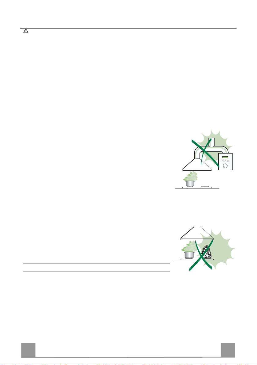
• Never leave high naked flames un der the hood when it is in operation.
• Adjust the flame intensity to direct it onto the bottom of the pan only, making
sure that it does not engulf the sides.
• Deep fat fryers must be continuously monitored during use: overheated oil can
burst into flames.
• The hood should not be used by children or persons not instructed in its correct use.
CARE
• Switch off or unplug the appliance from the main supply before carrying out
any maintenance work.
• Clean and/or replace the Filters after the specified time period.
• Clean the hood using a damp cloth and a neutral liquid detergent..
THERMAL PROTECTOR
The range hood is equipped with a thermal protector to avoid overheating conditions. If the range
hood shuts off in use, press the on/off button to return off range hood. Wait approximately 90
minutes, then press the on/off button to restart the range hood .
6
6
Page 7
EN
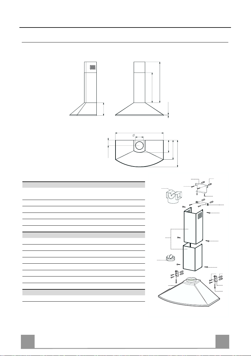
DIMENSIONS and MAIN PARTS
Dimensions
22" 1/16
26" 6/16 - 40" 9/16
9" 7/16
29" 29/32 - 35" 11/32
5" 29/32
3" 15/16
Components
Ref. Q.ty Product Components
1 1 Hood Body, complete with: Controls, Light, Blower,
Filters
2 1 Telescopic Chimney comprising:
2.1 1 Upper Section
2.2 1 Lower Section
10 1 Damper
15 1 Air Outlet Connection
Ref. Q.ty Installat i on Comp o nent s
7.1 2 Hood Body Fixing Bracket s
7.2.1 1 Upper Chimney Section Fixing Brackets
7.3 1 Air Outlet Connection Support
11 8 Wall Plugs (if supplied)
12a 8 Screws 3/16” x 1” 3/4
12c 6 Screws 1/8” x 3/8”
12d 2 Screws 3/16” x 1”
12e 2 Screws 1/8” x 1/2“
Q.ty Documentation
1 Instruction Manual
23/32"
9" 1/32
14" 5/32
18" 27/32 - 19" 21/32
7.3
15
10
12a
2.1
2
2.2
1
11
12e
7.2.1
12c
12c
12c
12a 11
7.1
12d
7
7
Page 8
EN
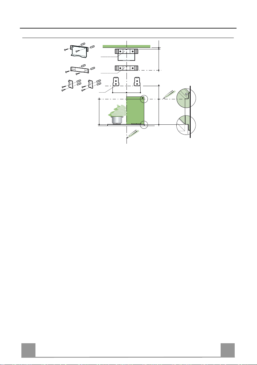
INSTALLATION
Wall drilling and bracket fixing
7.3
7.2.1
7.1
4" 5/16
4" 5/16
24"
Wall marking:
• Draw a vertical line on the supporting wall up to the ceiling, or as high as practical, at the
center of the area in which the hood will be installed.
• Draw a horizontal line at 24” above the hob for installation without the back panel, or at
height H (height of the visible part of the panel) for installation with the back panel.
• Place bracket 7.3 on the wall as shown about 1/16” from the ceiling or upper limit, aligning
the center (notch) with the vertical reference l ine.
• Mark the wall at the centers of the holes in the bracket.
• P l ace br acket 7.2.1 on the wall as shown at X” below the first bracket (X = height of the upper chimney section supplied), aligning the center (notch) with the vertical line.
• Mark the wall at the centers of the holes in the bracket.
• Place bracket 7.1 as shown 4” 5/16 from the vertical reference line and 7” 1/2 above the
horizontal reference line.
• Mark the centres of the holes in the bracket.
• Repeat this operation on the other side.
REAR PANEL (OPTIONAL)
The Rear Panel must be fitted before fixing the hood body and, if it is to be fixed at both top
and bottom, must be fitted at the correct height prior to installing the bases. As this operation is
rather complex, it should be carried out either by the kitchen installer or a qualified person
who knows the final dimensions of the units.
For fixing at the top only, proceed as follows:
• Rest the b ack panel o n th e base, i nsertin g the lo wer plate bet ween t he upper su rface and t he
wall, centring it on the vertical reference line.
• Mark the centres of the two holes in the up per plate.
• Drill ø 5/16” holes at all the centre points marked.
• Insert the wall plugs 11 in the holes.
• Fix the brackets using the 12a screws supplied.
• Fix the back panel (where present) using the 12a screws supplied.
÷1/16"
X
7"1/2
H
8
8
Page 9
EN
Mounting the hood body
12.d
7.1
• Screw the two screws 12d supplied onto the brackets 7.1.
• Hook the hood body onto the bracket 7.1, centring it around
the vertical line.
• Use th e adj ust ing screws 12d underneath the hood to level the
hood body.
Note: The Hood body should be secured to wall studs. If necessary, install a wood support behind the dry wall, flush mounted
between 2 studs. This will provide the necessary structure and
support for mounting.
Connections
DUCTED VERSION AIR EXHAUST SYSTEM
When installing the ducted version, connect the hood to the
chimney using a rigid 6” duct.
• Install the damper 10 ø 6”.
• Fix the duct in position using sufficient pipe clamps (not supplied).
10
DUCTLESS VERSION AIR OUTLET
• Put connection 15 into the connection support 7.3.
• Fix to the support using the 2 screws 12e supplied
• Connect the ai r outlet connection 15 to the hood body outlet
using either a rigid ø 6” pipe(not supplied).
• Ensure that the activated charcoal filters have been inserted.
15
12e
9
9
Page 10

EN 110
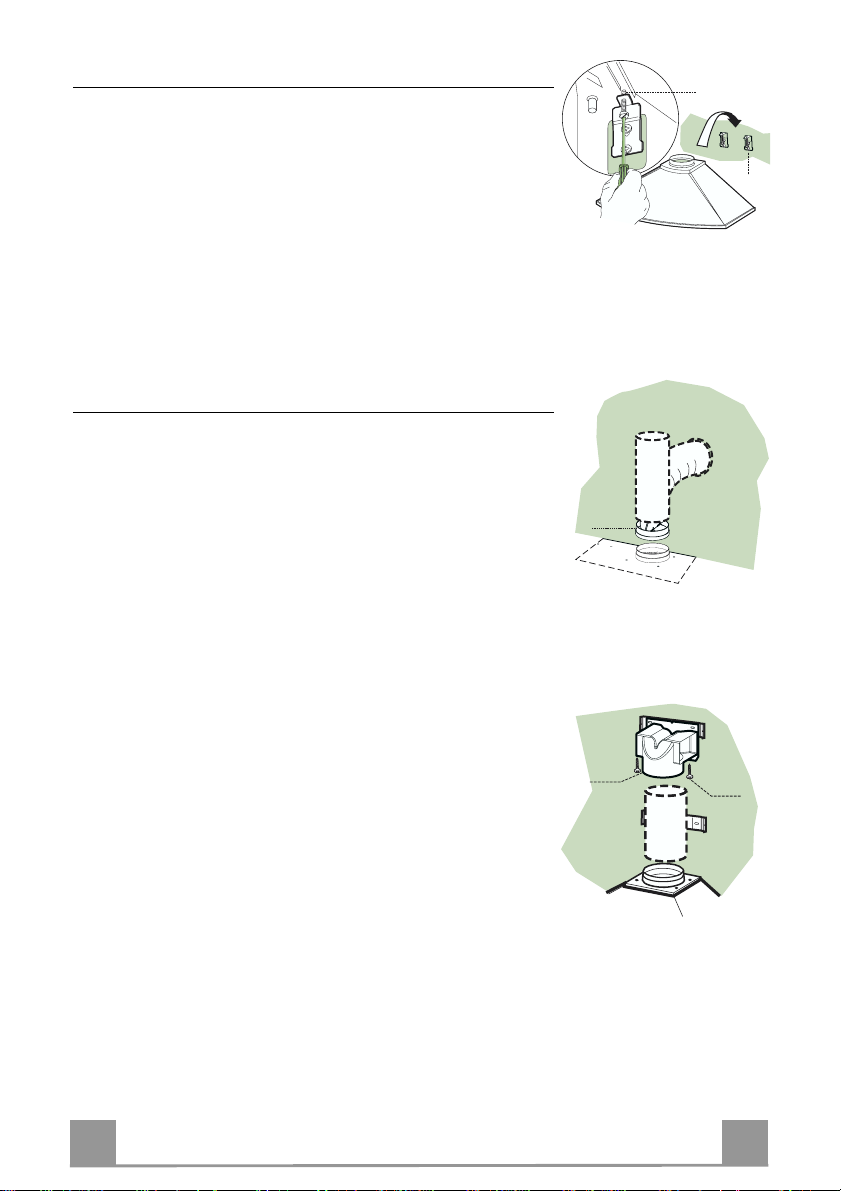
ELECTRICAL CONNECTION
• Remove the cover from the F ield Wiring Compartment with a
phillips screwdriver.
• Feed the Power Supply Cable through the electrical knockout.
Connect the Power Supp ly Cable to th e range- ho od cab le. Attach the Power Supply Cable grounding lead to the green screw
provided. Attach the White lead of the power supply to the
White lead of the rangehood with a twist-on type wire connector. Attach the Black lead of the power supply to the Black
lead of the rangehood with a twist-on type wire connector.
• Replace the cover.
Chimney assembly
Green
Ground
screw
Ground wire
Power supply cable
Upper exhaust Chimney
• Slightly widen the two sides of the upper flue and hook them
behind the brackets 7.3 and 7.2.1, making sure that they are
well seated.
• Secure th e sides to the brackets using the 4 screws 12c sup-
plied.
• Make sure that the air outlet connection is aligned with the
chimney outlets.
Lower exhaust Chimney
• Slightly widen the two sides of the chimney and hook them
between the upper chimney and the wall, making sure that they
are well seated.
• Fix the lower part laterally to the hood body using the 2 screws
12c supplied.
12c
2.1
2
2.2
12c
12c
Page 11

EN 111
USE
ing this key it is possible to activate
A
B
D
C
E
GH
F
Control board
Key Function Display
Switches the blower motor on and off at the
A
latest selected speed
Decreases the vent speed.
B
Increases the vent speed.
C
By press
D
the intensive speed from any previously selected speed . The intensiv e speed can be acti vated even when th e motor is O FF. Th is speed
has been timed at 10 minutes. After that time
the system activates automatically the latest
selected speed. This function is recommended
for cooking conditi on where vapors and odors
need to be eliminated immediately and quickly.
By pressing this key it is possible to set up the
E
motor to a suction speed at 60 CFM lasting 10
minutes every hour. After this the motor
switches off automatically.
When the filter saturation is going on it is possible to reset the alarm by pressing this key for
about 3 seconds. The indication i s visible only
when the motor is off.
By pressing this key it is possible to set the
F
delayed shutdown of the appliance to 30 minutes. This function is suitable for a complete
elimination of the residual odors. It can be activated at an y positi on, and it i s deactivat ed by
pressing the key again or by switching off the
motor.
Turns light on and off .
G
Turns light on and off a t reduced intensity.
H
Indicates the selected speed.
HI appears. The sp ot down on the right side
flashes once a second.
Indicates the 24-function. The spot down on
the right side flashes and the motor is on.
Once the process is finished the previous indication disappear s :
FF Indicates that the metal grease filters
EF Indicates that the charcoal filter satura-
Indicates both the selected speed of the hood
and the time left before the hood shutdown.
The spot down on the right side flashes alt ernately displaying the speed and shutdown time.
saturation a larm has been t riggered, and
the filters need to be washed. Th e alarm
is triggered after 100 working hours.
tion alarm has been triggered, and the filter has to be replaced; the metal grease
filters must also be washed. The charcoal
filter is triggered after 200 working hours.
Page 12

EN 112
CARE
REMOTE CONTROL (OPTIONAL)
This range hood can be controlled by a multi-function remote
control available through your local Franke Dealer.
Metal grease filters
Filters can be washed in the dishwasher. They need to be washed
when FF-sign appears on the display or in any case every 2
months, or even more frequently in case of particularly intensive
use of the hood.
Alarm reset
• Switch off the hood and the lights. If the 24h-function has been
activated this has to be deactivated.
• Press the E-key till the display is unlit.
Cleaning the filters
• Remove the filters one at a time holding them up with one
hand and pulling the handle downwards with the other hand at
the same time.
• Wash the filters, taking care not to bend them. Allow them to
dry before refitting.
• When refitting the filters, make sure that the handle is visible
on the outside.
Page 13

EN 113
A
B
Charcoal filter (ductless version)
• This filter cannot be washed or regenerated. It must be replaced when the EF appears on the
display or at least once every 4 months.
Activation of the alarm signal
• In the recycling version hoods the filter saturation alarm must be activated during the installation or later.
• Switch off the hood and the lights.
• Disconnect the hood from the main voltage supply.
• After restoring the connection press and hold B-key.
• When releasing the key two rotating rectangles appear on the display.
• Within 3 seconds press the B-key until a flashing confirmation appears on the dispaly:
• 2 flashes with EF - charcoal filter saturation alarm ACTIVATED
• 1 flash with EF - charcoal filter saturation alarm DEACTIVATED.
REPLACING THE CHARCOAL FILTER
Reset of the alarm signal
• Switch off the hood and the lighting. If the 24h-function has
been activated this has to be deactivated.
• Press the E-key until the display is unlit.
Replacing of the filter
• Remove the metal grease filters
• Re move the saturated activated charcoal filter as shown (A).
• Fit the new filters (B).
• Replace the metal grease filters.
Lighting
LIGHT REPLACEMENT
20 W halogen light.
• Remove the snap-on lamp cover by levering it from under the
metal ring, supporting it with one hand.
• Remove the halogen lamp from the lamp holder by pulling
gently.
• Replace the lamp with a new one of the same type, making
sure that you insert the two pins properly into the housings on
the lamp holder.
• Replace the snap-on lamp cover.
Page 14

114
TABLE DES MATIÈRES
AVERTISSEMENT ET CONDITIONS N ÉCESSAIRES......................................................................................................14
CONSEILS ET SUGGESTIONS ..........................................................................................................................................17
DIMENSIONS et PRINCIPALES PIÈCES............................................................................................................................18
INSTALLATION ....................................................................................................................................................................19
UTILISATION........................................................................................................................................................................22
SOIN ET ENTRETIEN..........................................................................................................................................................23
14
FR
Page 15

115
LIRE ET CONSERVER CES INSTRUCTIONS
L’installateur doit laisser ces instructions au propriétaire.
Le propriétaire doit conserver ces instructions en vue d’une utilisation subséquente et pour le bénéfice de l’inspecteur en él ectricité.
LISEZ BIEN CETTE FICHE AVANT D’UTIL ISER LA HOTTE
AVERTISSEMENT – POUR MINIMISER LE RISQUE D’UN FEU DE GRAISSE SUR LA CUISI-
NIÈRE : Ne jamais laisser un élément de la surface fonctionner sans surveillance à la puissance de chauffage
maximale; un renversement/débordement de matière graisseuse pourrait provoquer un incendie ou causer de
la fumée. Utiliser toujours une puissance de chauffage moyenne ou basse pour faire chauffer de l'huile.
Veiller à toujours faire fonctionner le ventilateur de la hotte lors d’une cuisson avec une puissance de chauffage élevée ou lors de la cuisson d ’un mets à flamber (i.e. Crêpes Suzett e, Cherries Jubi lee, Peppercorn Beef
Flambé). Nettoyer fréquemment les ventilateurs d’extraction. Veiller à ne pas laisser de la graisse
s’accumuler sur les surfaces du ventilateur ou des filtres. Utiliser toujours un ustensile de taille appropriée.
AVERTISSEMENT
DÉCLENCHEMENT D’UN FEU DE GRAISSE SUR LA CUISINIÈRE, APPLIQUER LES RECOMMANDATIONS SUIVANTES : Blessures en cas de feu suivre les recommandations suivantes :
ÉTOUFFEZ LE FEU AVEC UN COUVERCLE MÉTALLIQUE ET FERMEZ LE BRÛLEUR. FAITES
ATTENTION DE NE PAS VOUS BRÛLER. SI LE FEU NE S’ÉTEINT PAS IMMÉDIATEMENT, quit-
tez les lieux et appelez les pom piers. ne touc hez jamais une casserole en flam mes – VOUS POURRIEZ
SUBIR DES BLESSURES. N’UTILISEZ JAMAIS DE L’EAU OU UN TORCHON MOUILLÉ POUR
ÉTEINDRE LE FEU – CE QUI POURRAIT CAUSER UNE EXPLOSION DE VAPEUR.
brûlante.
connaît le fonctionnement. 2. Il s’agit d’un petit feu encore limité à l’endroit où il s’est déclaré. 3. Les pompiers ont été contactés. 4. Il est possible de garder le dos orient é vers une sorti e pendant l’opération de lutte
contre le feu.
Utiliser un extincteur SEULEMENT si :1. Il s’agit d’un extincteur de classe ABC, dont on
– POUR RÉDUIRE LE RISQUE DE DOMMAGES CORPORELS APRÈS LE
vapeur
N’utilisez un extincteur que si: 1. Vous avez sous la main un modèle ABC et vous comment
l’utiliser correctement. 2. Le feu est faible et peu répandu. 3. Les pompiers sont déjà prévenus. 4.
Vous conservez une sortie derrière vous
TOUTE OUVERTURE DANS LE MUR OU LE PLANCHER À PRO XIMITÉ DE LA HOTTE DOIT
ÊTRE SCELLÉ
.
Gardez 24 po. de hauteur en tre le bas d e la ho tte et la surface de cu isso n . Con sultez l a fiche tech nique avant de découper les armoires. INSTALLATION DANS UNE MAISON MOBILE.
L’installation de cette hotte doit être conforme aux règlements de Manufactured Home Construction and Safety Standards, Titre 24 CFR, Section 3280 (anciennement Federal Standard for Mobile Home Construction and Safety, Titre 24, HUD, Section 280). Le branchement électrique
s’effectue avec un raccordement à 4 fils. Consultez la Fiche Technique électrique.
EXIGENCES DE VENTILATION (ÉVACUATION)
ATTENTION – Afin de réduire le risque d’incendie et pour bien évacuer l’air, assurez-vous de faire échap-
per l’air des conduits à l’extérieur – Ne jamais évacuer l’air vers des espac es comportant des murs ou des
plafonds ou dan s le grenier, la galerie ou le garage.
Déterminer la mé thode d’évacuation de l’air la plus appropriée pour l’application. La sortie
d’evacuation : soit par le mur, soit par le toit. Utilisez une longueur de tuyauterie minimale, incluant le
moins de coudes p ossible pour une plus grande efficacité. Le calibre de la tuyauterie doit être uniforme. N’installez jamais 2 coudes ensembles. Scel lez bien tous les joints avec un ruban adhésif métallique à l'intérieur et scellez bien le clapet extérieur en utilisant du calfeutrage.
L’utilisation d’un tuyau d’évacuation flexible n’est pas recommandée. Les tuyaux flexi bles
créent une contre-pression et de la turbulence, ce qui réduit la puiss ance d'évacuat ion.
Veillez à ce que l’espace pour le tuyau soit amplement suffis ant, ainsi vous n’aurez pas à découper les supports de mur intérieur. On ne doit couper une solive ou un poteau de colombage que
lorsque cela est absolument nécessaire. S’il est nécessaire de couper une solive ou un poteau du
colombage, on doit construire une structure de su pport appropriée.
AVERTISSEMENT – Afin de réduire le risque d ’incendie, u tilisez seulemen t des condu its en métal.
15
FR
Page 16

116
AVERTISSEMENT
• Le système d’évacuation DOIT se terminer à l’extérieur.
• N’ÉVACUEZ PAS le conduit dans u n grenier ou dans tout autre espace fermé.
• N’UTILISEZ PAS un clapet de sécheuse à 4 pouces.
• ON DÉCONSEILLE l’emploi de conduit d’évacuation flexible.
• N’ENCOMBREZ PAS la circulation d’air.
• Le fait de ne pas respecter ces avertissements pourrait occasionner un incendie.
FICHE TECHNIQUE ÉLECTRIQUE
Le raccordement électrique d oit se faire avec un ci rcuit séparé de 15 ampères fusi bles à 120 V,
60 Hz, courant alternatif. Nous recommandons un coupe-circuit. La taille du fusible doit se
conformer aux codes municipaux suivant la spécification électrique sur la plaque intérieure. CET
APPAREIL NE DOIT ÊTRE CONNECTÉ QU’EN UTILISANT DES FILS EN CUIVRE. Le
diamètre du fil devra aussi se conformer aux règlements du code national électrique,
ANSI/NFPA 70, ain si qu ’aux règlemen ts lo caux et les sp éci ficatio n s de cet app areil . On peut obtenir ces informations auprès de :
National Fire Protection Association
Batterymarch Park
Quincy, Massachusetts 02269
Raccordez cet appareil directement au coupe-circuit( ou au disjoncteur) par l’intermédiaire de
câble à conducteurs de cuivre, à blindage métallique flexible ou à gaine non-métallique. Un
serre-câble
de ½ po. (12,7 mm) (homologation UL ou CSA) doit être installé à chaque extré-
mité du câble d'alimentation (sur la hotte et sur le boîtier de distribution).
Faites un trou de 1 ¼ po. dans le mur. S’il s’agit d'un mur en bois, sablez bien le trou. Tandis
qu'un trou dans le métal demande un oeillet (passe-fil).
AVERTISSEMENT – POUR RÉDUIRE LE RISQUE D’INCENDIE OU DE CHOC ÉLECTRIQUE,
ne pas utiliser ce ventilateur en conjonction avec un dispositif de réglage de vitesse à semi-
conducteurs.
AVERTISSEMENT – POUR MINIMISER LES RISQUES D’INCENDIE, CHOC ÉLECTRIQUES OU BLESSURES, OBSERVER CETTE RÈGLE :
fabricant ; en cas de nécessité veuillez le contacter.
suivez strictement les recom mandations du
Avant d’entreprendre un travail d’entretien ou de nettoyage, interrompre l’alimentation de la
hotte au niveau du tableau de disjoncteur, et verrouiller le tableau de disjoncteur pour empêcher
tout rétablissement accid entel de l’alimentation du circui t. Lorsqu’il n’est pas possible de verrouiller le tableau de disjoncteur une étiquette d’avertissement proéminent interdisant le rétablissement de l’alimentation.
IMPORTANT :
l’évacuation de matières ou vapeurs explosives.
Pour une ventilation de type général seulement. Ne pas utiliser cet appareil pour
16
FR
Page 17

117
AVERTISSEMENT – POUR MINIMISER LES RISQUES D’INCENDIE, CHOC ÉLECTRIQUES OU BLESSURES, OBSERVER CETTE RÈGLE :
ne doivent être effectués que par un technicien(s) qualifié, selon tous les codes municipaux
Afin d’obtenir un rendement maximal en ce qui a trait à la combustion ainsi qu’à l’évacuation
des gaz par la conduite de cheminée et pour qu’il n’y ait pas de reflux des gaz de combustion, une bonne aérat ion est nécessaire pour tous les appareils à combustion. Sui vez les
conseils et mesures de sécurité du fournisseur tels que ceu x publiés par la National Fire Protection Associ ation (NFPA) et l’American Society for Heating, Refrigeration and Air Condition
Engineers (ASHRAE) ai nsi que les codes municipaux.
Lors d’opération de découpage et de perçage dans un mur ou un plafond, veiller à ne pas
endommager les câblages électriques ou canalisations qui peuvent s’y trouver.
Un conduit de ventilation doit toujours se terminer à l'extéri eur.
AVERTISSEMENT
• Une prise à la terre est nécessaire pour cette hotte.
• N’UTILISEZ PAS un tuyau à l’eau froide po ur la mise à la terre s’il est connecté à du
plastique, un joint non métallique ou autre matériel.
• N’EFFECTUEZ PAS la mise à la terre sur la conduite de gaz.
• NE PAS INSTALLER un fusible dans le conducteur neutre ou le conducteur de liaison à
la terre.
• Vérifiez avec un électricien qualifié que la hotte est bien mise à la terre.
• Le fait de ne pas respecter ces avertissements pourrait occasionner un incendie.
l’installation et le raccordement électrique
.
17
FR
Page 18

118
CONSEILS ET SUGGESTIONS
Les instructions d’utilisation s’applique à plusieurs versions de ce type
d’appareil. En conséquence, il est possible que vous trouviez des descriptions
de caractéri stiques ne s'appliquant pas à votre app areil.
INSTALLATION
• Le fabricant décline toute responsabilité en cas de dommage dû à une installation inadéquate ou non conforme aux règles de l’art.
• Vérifiez que la tension du secteur correspond à la valeur qui figure sur la plaquette apposée à l’intérieur de la hotte.
• L’alimentation électrique doit être adéquatement et suffisamment mise à la
terre.
Connectez la hotte à la sortie de l’air aspiré à l’aide d’une tuyauterie d’un dia-
mètre ou supérieur à 6 po. Le parcours de la tuyauterie doit être le plus court
possible.
• Évitez de connecter la hotte à des conduites d’évacuation de fumées issues
d’une combustion tel que une chaudière, une cheminé e, etc.
• Si vous utilisez des appareils qui ne fonctionnent pas à l’électricité dans la
pièce ou est installée la hotte (par exemple : des appareils fonctionnant au
gaz), vous devez prévoir une aération suffisante de l’espace. Si la cuisine en
est dépourvue, pratiquez une ouverture qui communique avec l’extérieur pour
garantir l’infiltration de l’air pur.
UTILISATION
• La hotte a été conçue exclusivement pour un usage domestique, dans le but
d’éliminer les odeurs de la cuisine.
• Ne jamais utiliser la hotte de manière abusive.
• Ne pas laisser les fla mmes libres à forte intensité lorsque la hotte e st en service.
• Toujours régler les flammes de manière à éviter toute sortie latérale de ces
dernières par rapport au fond des casser oles.
• Contrôler les friteuses lors de l’utilisation, car l’huile surchauffée pourrait
s’enflammer
• La hotte ne do it pas ê tre u tilisée pa r des e nfant ou d es p ersonne s ne pouvan t
pas en assurer une utilisation adéquate
ENTRETIEN
• Avant de procéder à toute opération d’entretien, retirer la hotte en la débranchant ou en la mettant hors -c i rc uit .
• Effectuer un entretien scrupuleux et en temps voulu des filtres.
• Pour le nettoyage des surface s de la hotte, il suffit d ’utilise r un linge humide et
un détergent l iquide neutre.
PROTECTEUR THERMIQUE
Cette hotte est équipée d’un protecteur thermique afin de prévenir le surchauffage. Si la hotte s'éteint en cours d'utilisat ion, appuyez sur le bouton en marche/arrêt afin de remettre la hotte en position Arrêt. Attendez environ 90 minu-
tes, puis appuyez de nouveau sur l e bouton en ma rche/arrêt pou r redémarre r la
hotte.
18
FR
Page 19

FR 119
DIMENSIONS et PRINCIPALES PIÈCES
Dimensions
22" 1/16
26" 6/16 - 40" 9/16
9" 7/16
29" 29/32 - 35" 11/32
5" 29/32
3" 15/16
Composantes
Ref. Qté Pièces du produit
1 1 Corps de la hotte équipé de : commandes, lumière,
groupe ventilateur, filtres
2 1 Cheminée téles copique formée de :
2.1 1 Cheminée supérieure
2.2 1 Cheminée inférieure
10 1 Clapet anti-reflux
15 1 Raccord de sortie d’air
Ref. Qté Pièces servant à l’installation
7.1 2 Brides de montage de la hotte
7.2.1 1 Brides de montage de la cheminée supéri eure
7.3 1 Bride de raccord de sortie d’air
11 8 Chevilles (si fournies)
12a 8 Vis 3/16” x 1” 3/4
12c 6 Vis 1/8” x 3/8”
12d 2 Vis 3/16” x 1”
12e 2 Vis 1/8” x 1/2“
Qté Documentation
1 Manuel d’instructions
23/32"
9" 1/32
14" 5/32
18" 27/32 - 19" 21/32
7.3
15
10
12a
2.1
2
2.2
1
11
12e
7.2.1
12c
12c
12c
12a 11
7.1
12d
Page 20

FR 220
INSTALLATION
Perçage de la paroi et fixation des brides
7.3
7.2.1
÷1/16"
X
24"
7.1
4" 5/16
7"1/2
H
4" 5/16
Marquage au mur :
• Tracer une ligne verticale sur le mur de support jusqu’au plafond, ou aussi haut que nécessaire, au centre de la surface sur laquelle la hotte sera install ée.
• Tracer une ligne horizontale à 24 po. au dessus du piquet pour installation sans panneau arrière, ou à la hauteur H (hauteur de la partie visible) pour l’installation avec panneau arrière.
• Placer le support 7.3 sur le mur comme indiqué, à environ 1/16 po. du plafond ou de la limite supérieure, en alignant le centre (entaille) sur la ligne verticale de référence.
• Marquer le mur au niveau des centres des trous du support.
• P l acer le sup port 7.2.1. sur le mur comme indiqué à X po. en dessous du premier support (X
= hauteur de la section supérieure de cheminée, incluse), en alignant le centre (entaille) sur
la ligne verticale.
• Marquer le mur au niveau des centres des trous du support.
• P lacer l e supp or t 7.1 comme indiqué à 4 po. 5/16 de la ligne verticale de référence et à 7 po.
1/2 au dessus de la ligne horizontale de référence.
• Marquer les centres des trous du support.
• Répéter la même opération de l’autre côté.
PANNEAU ARRIÈRE (OPTION)
Le panneau arrière doit être monté avant de fixer le corp s de hotte et, s’il do it être fixé en haut
et en bas, il doit être monté à la bonne hauteur avant d’installer les bases. Cette opération étant
plutôt complexe, elle doit être exécutée par le monteur de la cuisine ou toute autre personne
qualifiée connaissant les dimensions définitives des unités.
Pour fixer en haut seulement, procéder comme suit :
• F aire reposer le panneau arrière sur l a base en insérant le plateau i nférieur entre la surface
supérieure et le mur et en le centrant sur la ligne verticale de référence.
• Marquer les centres des deux trous du plateau supérieur.
• Percer des trous de 5/16 po. de diamètre sur tous les points marqués.
• Insérer les fiches murales 11 dans les trous.
• Fixer les supports avec les vis 12a fournies.
• Fixer le panneau arrière (le cas échéant) avec les vis 12a fournies.
Page 21

FR 221
12.d
7.1
Montage du corps de la hotte
• Vis les deux vis 12d accompagnant les supports 7.1.
• Accrocher le corps de hotte sur le support 7.1, en le centrant
autour de la ligne verticale.
• Utiliser les vis de réglage 12d en dessous de la hotte pour
mettre le corps de hotte à niveau.
Note : Le corps de hotte doit être fixé aux goujons muraux. Si
nécessaire, installer un support en bois derrière le mur sec, monté
à ras des 2 goujons. Cela assurera la structure requise et le support de montage.
Branchements
SORTIE D’AIR VERSION ASPIRANTE
En cas d’installation en version aspirante, brancher la hotte à la
tuyauterie de sortie via un tube rigide de 6 po.
• Installer le clapet d’air 10 ø 6 po.
• Fixer le tu be par des colliers appropriés. Le matériel nécessaire n’est pas fourni.
SORTIE D’AIR, VERSION NON CARÉNÉES
• Placer le raccord 15 dans le support de connexion 7.3.
• Fixer au support avec les 2 vis 12e fournies.
• Raccord er la connexion de sortie d’air 15 à la sortie du corps
de hotte avec un tuyau rigide de diamètre 6 po. (non inclus).
• S’assurer que les filtres à charbon activé ont été insérés.
10
15
12e
Page 22

FR 222
BRANCHEMENT ÉLECTRIQUE
• Retirer le couvercle du compartiment de filage à l’aide d’un
tournevis Phillips.
• Passer le câble d’alimentation dans la pastille enfonçable.
Brancher le câble d’alimentation sur la hotte. Attacher le
conducteur de mise à la terre du câble d’alimentation à la vis
verte fournie. Attacher l e fil blanc du câble d’alimentation au
fil blanc de la hotte av ec une cosse (connecteu r de fils). Attacher le fil noir du câble d’alimentation au fil noir de la hotte
avec une cosse (connecteur de fils).
• Replacer le couvercle.
Vis moulue
verte
Fil de masse
Câble d'alimentation
d'énergie
Montage de la cheminée
Cheminée d’échappement supér ieure
• Élargir légèrement les deux côtés de l’évacuation supérieure et
les accrocher derrière les supports 7.3 et 7.2.1 en s’assurant
qu’ils sont tous deux bien assis.
• Fixer les côtés aux supports avec les 4 vi s 12c fournies.
• S’assurer q ue le raccord à la sortie d’air est en ligne avec les
prises de cheminée.
Cheminée d’échappement inférieure
• Élargir légèrement les deux côtés de l’évacuation supérieure et
les accrocher entre la cheminée supérieure et le mur en
s’assurant qu’ils sont tous deux bien assis.
• Fixer la partie inférieure latéralement au corps de hotte en utilisant les 2 vis 12c fournies.
12c
2.1
2
2.2
12c
12c
Page 23

FR 223
UTILISATION
A
B
D
C
E
GH
F
Tableaux des commandes
Touche Fonction Afficheur
Allume et éteint le moteur de ventilation à la
A
dernière vitesse utilisée
Diminue la vitesse de ventilation.
B
Augmente la vitesse de ventilation.
C
Active la vitesse intensive à partir de n’importe
D
quelle vitesse, même du moteur arrêté. Cette
vitesse est programmée pour durer 10 minutes,
après quoi le système retourne à la vitesse réglée au préalable. Sert à faire face à une quantité maximale de fumée de cuisson, lorsqu'il est
nécessaire d’éliminer vapeurs et odeurs rapidement et immédiatement.
Active le moteur à une vitesse permettant une
E
aspiration de 60 CFM pendant 10 minutes toutes les heures, puis le moteur s’arrête.
Quand l’ala rme filtres est déclenchée, appuyer
sur cette touche pendant 3 secondes environ
pour remettre l’alarme à l’état initial. Ces indications sont visibles uniquement quand le
moteur est éteint.
Active l’arrêt automatiquement retardé de 30
F
minutes. Utile pour achever d'éliminer toute
odeur résiduelle. S’active depuis toutes les
positions et se désactive en appuyant sur la
touche ou en éteignant le moteu r .
Allume et éteint la lumière.
G
Allume et éteint la lumière à intensité réduite.
H
Affiche la vitesse sélectionnée.
Affiche HI et le point en bas à droite clignote
une fois par seconde.
Affiche 24-function. Le point en bas à droite
clignote, quand le moteur fonctionne.
En fin de procédure, le signal affiché précédemment s’éteint :
FF indique qu’il faut laver les filtres à
graisse métalliques. L’alarme se déclenche après 100 heures de fonctionnement
effectif de la hotte.
EF Indique qu’il faut remplacer les filt res au
charbon actif et laver les filtres à graisse
métalliques. L’alarme se déclenche après
200 heures de fonctionnement effectif de
la hotte.
Affiche la vitesse de service et le temps restant
avant l'arrêt de la hotte. Le point en bas à
droite clignote, indiquant tour à tour la vitesse
et le temps restant.
Page 24

FR
24
SOIN ET ENTRETIEN
TÉLÉCOMMANDE (EN OPTION)
Cet appareil peut être contrôlé à l’aide d’un télécommande alimentée par une pile alcaline carbone-zinc de type AAA (1.5
volt).
Filtres à graisse métalliques
Ils sont lavables au lave-vaisselle et doivent être lavés chaque
fois que le symbole FF s’affiche ou environ tous les 2 mois, ou
plus souvent même, en cas d’utilisation particulièrement intensive.
Rétablissement du signal d’alarme
• Éteint les lumières et le moteur d’aspiration; au cas où la fonction 24h est active, il convient de la désactiver.
• Appuyer sur la touche E jusqu’à ce que l’afficheur s’éteigne.
Nettoyage des filtres
• Retirer les filtres, un à un, en les tenant d’une main et en tirant
simultanément vers le bas sur la poignée avec l’autre main.
• Laver les filtres en évitant de les plier, et les faire sécher avant
de les remonter.
• Remonter les filtres en faisant attention de tenir la poignée vers
la partie externe.
Page 25

FR
25
A
B
Filtre anti-odeur au charbon actif (version filtrante)
• Il ne peut être ni lavé, ni récupéré. Il faut le changer quand EF s'affiche ou au moins to us
les 4 mois.
Déclenchement du signal d’alarme
• Pour les hottes de la version filtrante, l’alarme indiquant la saturation des filtres doit être
activée au moment de l’installation ou ultérieurement.
• Éteindre les lumières et le moteur d’aspirati on.
• Débrancher la hotte du réseau électrique.
• Rétablir le branchement, puis presser et maintenir la touche B.
• Relâcher la touche et deux rectangles en rotation apparaissent sur l’afficheur.
• Dans les 3 secondes qui suivent, appuyer sur la touche B jusqu’à ce que s’affichent :
• EF clignotant deux fois – Alarme saturation filtre charbon actif ACTIVÉE
• EF clignotant une fois – Alarme saturation filtre charbon actif DÉSACTIVÉE.
REMPLACEMENT DU FILTRE ANTI-ODEUR AU CHARBON ACTIF
Rétablissement du signal d’alarme
• Éteint les lumières et le moteur d’aspiration; au cas où la fonction 24h est active, il convient de la désactiver.
• Appuyer sur la touche E jusqu’à ce que l’afficheur s’éteigne.
Changement des filtres
• Retirer les filtres anti-graisse métalliques.
• Retirer les filtres anti-odeur au charbon actif saturés, comme
indiqué (A).
• Monter les nouveaux filtres (B).
• Remonter le filtres anti-graisse métalliques.
Éclairage
REMPLACEMENT DES AMPOULES
Lampe halogène de 20 W.
• Enlever le dispositif métallique de blocage du verre par encliquetage en exerçant une pression sous l’embout en le soutenant
d’une main.
• Extraire la lampe du support
• Remplacer la lampe par u ne nouvelle ayant l e mêmes caractéristiques, en prenant soi n d'in sérer correcte ment les d eux fiches
dans le support.
• Re monter le dispositif de blocage du verre par encliquetage.
Page 26

Page 27

Page 28

436004251_01 - 080603
 Loading...