

Page 1
Instructions for use and installation
Istruzioni per l’uso e l’installazione
Mode d’emploi et installation
Bedienungsanleitung und Einrichtung
Kullan
ım ve montaj talimatları
Uživatelská P
øíruèka
GB
IT
FR
DE
TR
CZ
Cooker Hood
Cappa
Hotte de Cuisine
Dunstabzugshaube
Davlumbaz
Kapuce
FCR 908 TC
Page 2

FR DE TR CZ
INDEX
RECOMMENDATIONS AND SUGGESTIONS......................................................................................................................3
CHARACTERISTICS..............................................................................................................................................................4
INSTALLATION ......................................................................................................................................................................5
USE.........................................................................................................................................................................................8
MAINTENANCE......................................................................................................................................................................9
EN
INDICE
CONSIGLI E SUGGERIMENTI ............................................................................................................................................11
CARATTERISTICHE............................................................................................................................................................12
INSTALLAZIONE..................................................................................................................................................................13
USO......................................................................................................................................................................................16
MANUTENZIONE.................................................................................................................................................................17
IT
SOMMAIRE
CONSEILS ET SUGGESTIONS ..........................................................................................................................................19
CARACTERISTIQUES.........................................................................................................................................................20
INSTALLATION ....................................................................................................................................................................21
UTILISATION........................................................................................................................................................................24
ENTRETIEN..........................................................................................................................................................................25
INHALTSVERZEICHNIS
EMPFEHLUNGEN UND HINWEISE....................................................................................................................................27
CHARAKTERISTIKEN..........................................................................................................................................................28
MONTAGE............................................................................................................................................................................29
BEDIENUNG.........................................................................................................................................................................32
WARTUNG............................................................................................................................................................................33
IÇERIKLER
TAVSIYELER VE ÖNERILER ..............................................................................................................................................35
ÖZELLIKLER........................................................................................................................................................................36
MONTAJ...............................................................................................................................................................................37
KULLANIM............................................................................................................................................................................40
BAKIM...................................................................................................................................................................................41
OBSAH
RADY A DOPORUČENÍ.......................................................................................................................................................43
HLAVNÍ PARAMETRY .........................................................................................................................................................44
INSTALACE..........................................................................................................................................................................45
POUŽITÍ................................................................................................................................................................................48
ÚDRŽBA...............................................................................................................................................................................49
2
2
Page 3
EN
RECOMMENDATIONS AND SUGGESTIONS
The Instructions for Us e a pply t o seve ral versio ns of this appl ianc e. Ac cor
d-
650 mm min.
ingly, you may fin d descriptions of indi vidual features that d o not apply to
your specific appliance.
INSTALLATION
• The manufacturer will not b e held liable for any dam ages resulting fr om incorrect or i mpr op er in sta l lat ion .
• The minimum safety distance between the cooker top and the extractor
hood is 650 mm (som e m od el s can be installed at a lower height, please refer to the paragraphs on working dimensions and installation).
• Check that the mains voltage corres ponds to that indicated on t he rating
plate fixed to the inside of the hood.
• For Class I appliances, check th at the domestic power supply guarantees
adequate earthing.
Connect the extractor t o the ex haus t flu e throu gh a pipe o f mi nimum diame-
ter 120 mm. The route of the flue must be as short as possible.
• Do not connect the ex tractor hood to exhaust ducts ca rrying combustion
fumes (boilers, fireplaces, etc.).
• If the ext ra ctor is used in conjunction with non-electrical appliances (e. g. g as
burning applia nces), a suffi cient degree of aeration must be guarantee d in
the room in order to prevent t he backfl ow of exha ust gas. T he kitch en must
have an opening communicating directly with the open air in order to
guarantee the entry of clean air.
USE
• The extractor hood has been designed exclusively for domestic use to eliminate kitchen smells.
• Never use the hood for purposes other than for which it has been designed.
• Never leave high naked fla me s un der the ho od wh en it is in oper at i on.
• Adjust th e fl am e i n te nsity to direct it onto the bottom of t he pan only, making
sure that it does not engulf the sides.
• Dee p fat fryers must b e continuously m onitored durin g use: overheate d oil
can burst into flames.
• Do not flambè under the range hood; risk of fire
• This ap pliance is not i ntended for use by persons (includi ng children) with
reduced physical , sensory or mental capabilitie s, or lack of ex perience and
knowledge, unless th ey have been g iven su pervi sion o r in structi on con cern ing use of the appliance by a person responsible for their safety.
• Child re n sh ould be supervised to ensure that they do not play with the appliance.
MAINTENANCE
• Switch off or unplug the appliance from the m ains supply before carrying out
any maintenance work.
• Clean and/or replace the Filters after the specified time period (Fire hazard).
• Clean the hood using a damp cloth and a neutral liquid detergent.
The symbol on the product or on its packaging indicates that this product may not be treated
as household waste. Instead it shall be handed over to the applicable collection point for the
recycling of electrical and electronic equipmen t. By ensuring this pr o duct is disposed of correctly,
you will help prevent potential negative consequences for the environment and human health,
which could otherwise be caused by inappropriate waste handling of this product. For more
detailed information about recycling of this product, please contact your local city office, your
household waste disposal service or the shop where you purchased the product.
3
3
Page 4

EN
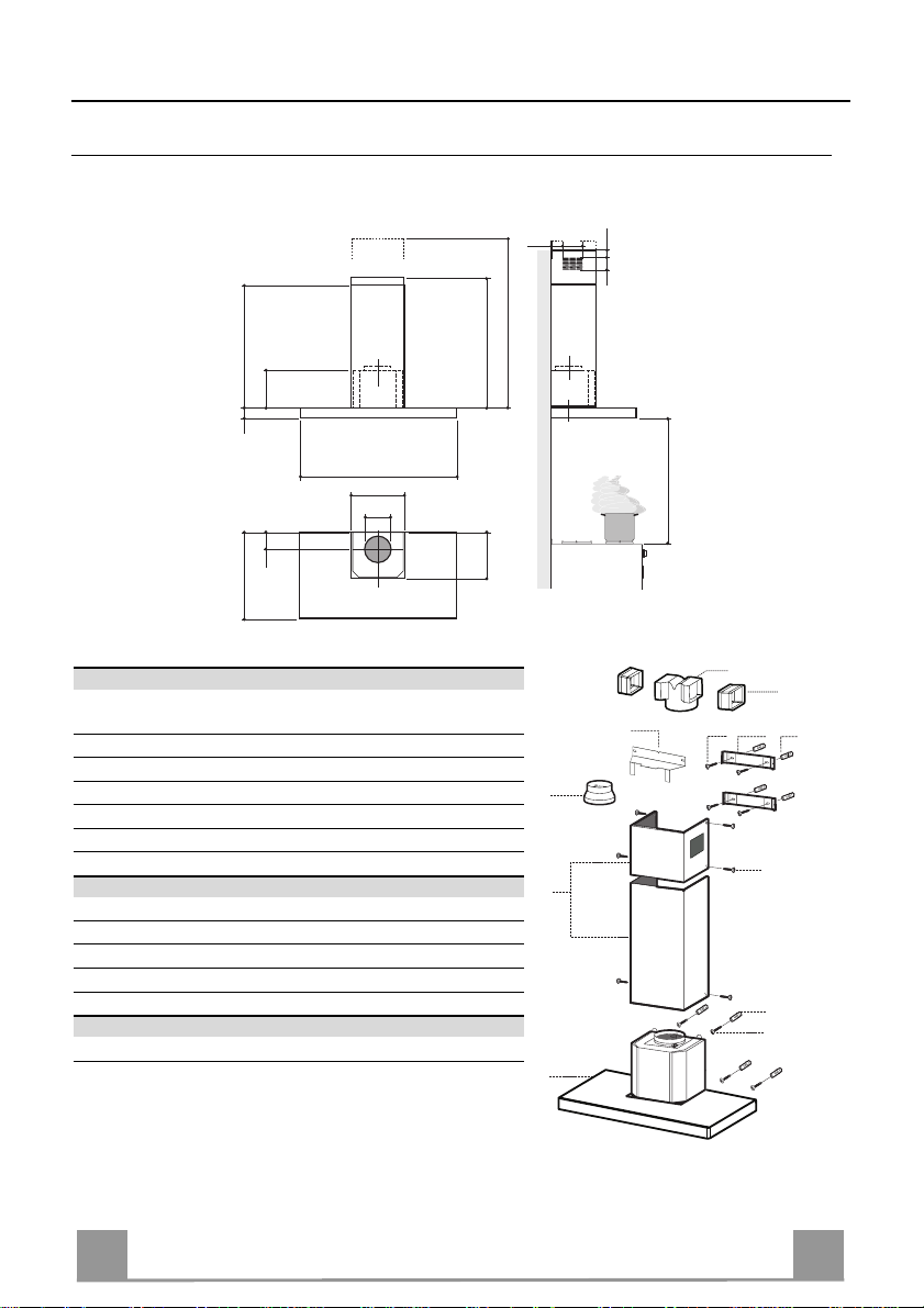
CHARACTERISTICS
Dimensions
6341126
81
540
60
898
300
150
108 259
485
max. 1000
min. 670
260
Components
Ref. Q.ty Product Components
1 1 Hood Body, complete with: Controls, Light, Blower,
Filters
2 1 Telescopic Chimney comprising:
2.1 1 Upper Section
2.2 1 Lower Section
9 1 Reducer Flange ø 150-12 0 mm
14.1 2 Air Outlet Connection Extension
15 1 Air Outlet Connection
Ref. Q.ty Installation Components
7.2.1 2 Upper Chimney Section Fixing Brackets
7.3 1 Air Outlet Connection Su pport
11 8 Wall Plugs
12a 8 Screws 4,2 x 44,4
12c 6 Screws 2,9 x 9,5
Q.ty Documentation
1 Instruction Manual
650 min.
15
14.1
7.3
9
2.1
2
2.2
1
12a
7.2.1 11
12c
11
12a
4
4
Page 5
EN
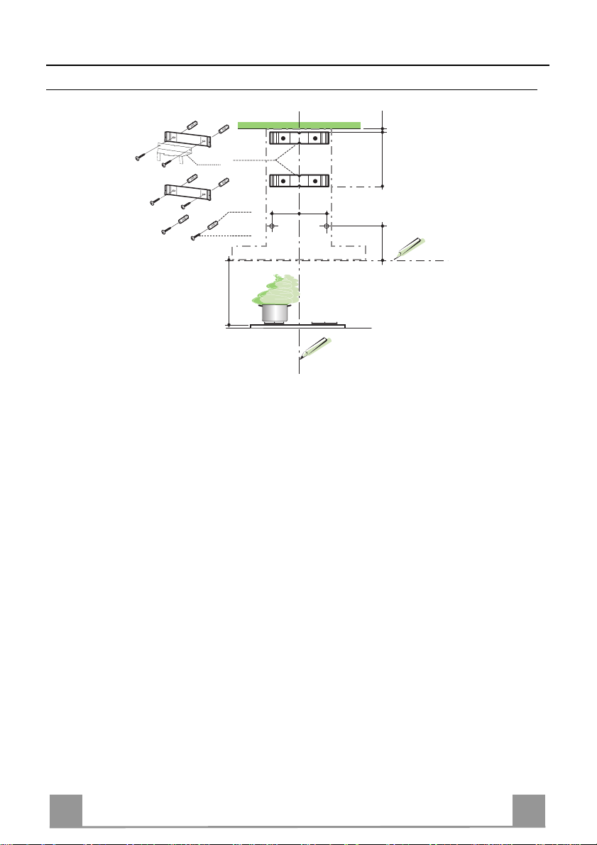
INSTALLATION
Wall drilling and bracket fixing
7.2.1
7.3
11
12a
116
116
650 min.
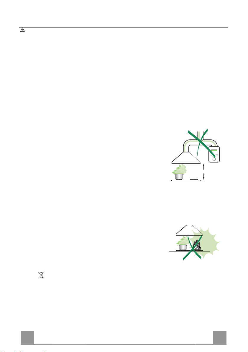
Wall marking:
• Draw a vertical line on the supporting wall up to the ceiling, or as high as practical, at the
centre of the area in which the hood will be installed.
• Draw a horizontal line at 650 mm above the hob.
• P l ace bracket 7.2.1 on the wall as shown about 1-2 mm from the ceiling or upper limit aligning the centre (notch) with the vertical reference line.
• Mark the wall at the centres of the holes in th e br acket.
• P l ace br acket 7.2.1 on the wall as shown at X mm below the first bracket (X = height of the
upper chimney section supplied), aligning the centre (notch) with the vertical line.
• Mark the wall at the centres of the holes in th e br acket.
• Mark a reference point as in dicated at 116 mm from the vertical reference li ne and 320 mm
above the horizontal reference l ine.
• Repeat this operation on the other side.
• Drill ø 8 mm holes at all the centre points marked.
• Insert the wall plugs 11 in the hole s.
• Fix the lower bracket 7.2.1 using the 12a screws (4,2 x 44,4) supplied.
• Fix the upper bracket 7.2.1 and the air outlet connection supp ort 7.3 to gether using the 2
screws 12a (4,2 x 44,4) supplied.
• Insert the two screws 12a (4,2 x 44,4) supplied in the hood body fixing holes, leaving a gap
of 5-6 mm between the wall and the head of the screw.
1÷2
X
320
5
5
Page 6
EN
Mounting the hoo d body
9
ø 120ø 150
ø 150
15
14.1
7.3
• Before attaching the hood body, tighten the two screws Vr located on
the hood body mo unt i ng points.
• Hook the hood bod y onto the screws 12a.
• Fully tighten s upport screws 12a.
• Adjust screws Vr to level the hood body.
• If necessary, it is possible to fasten the hood to the wall using more
screws with wall plugs, which can be positioned from inside the hood
canopy.
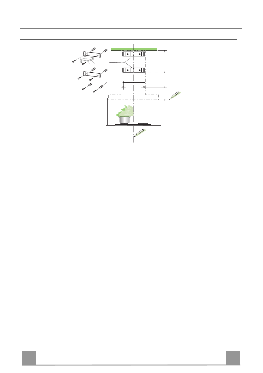
Connections
DUCTED VERSION AIR EXHAUST SYSTEM
When installing the ducted version, connect the hood to the
chimney using either a flexible or rigid pipe ø 150 or 120 mm,
the choice of which is left to the installer.
• To install a ø 120 mm air exhaust connection, insert the reducer flange 9 on the hood body outlet.
• Fix the pipe in position using sufficient pipe clamps (not supplied).
• Remove any activated ch arcoal filters.
Vr
12a
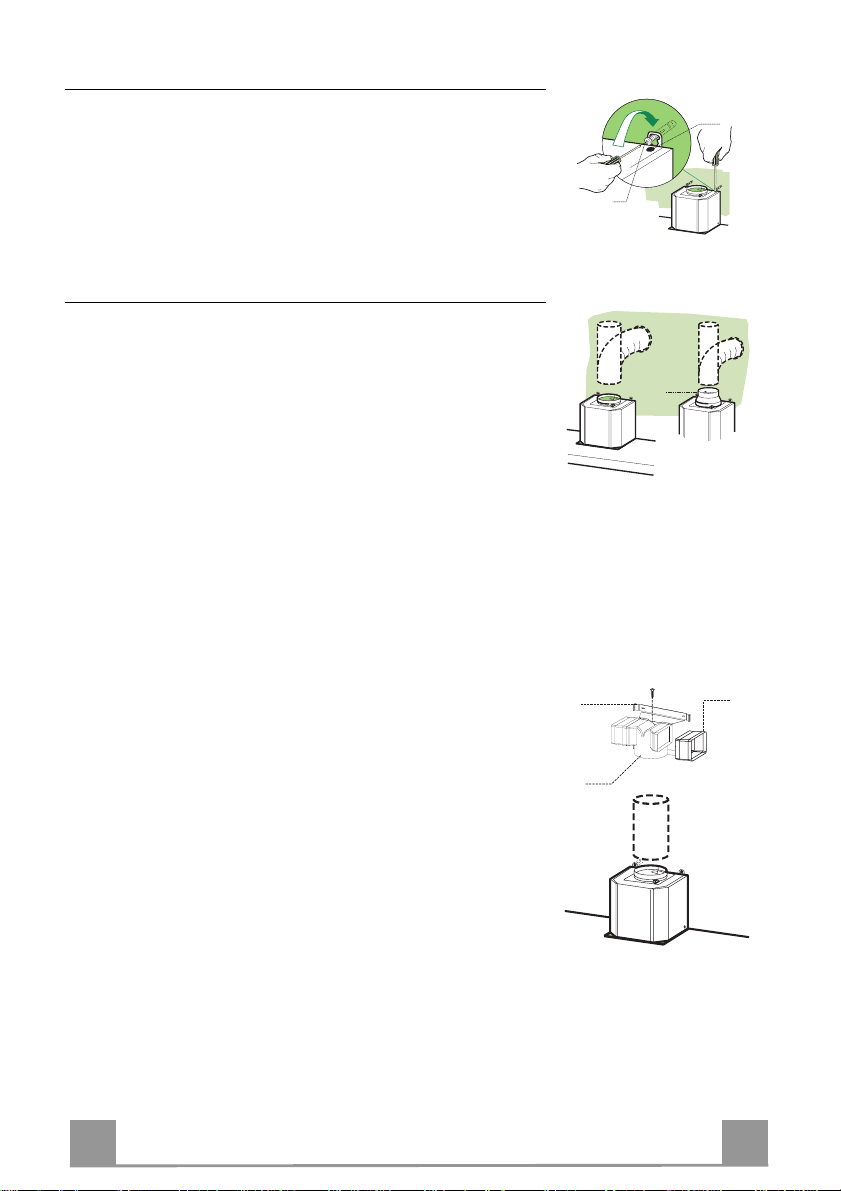
RECIRCULATION VERSION AIR OUTLET
• Insert the connection exten sion pieces lat erally 14.1 in co nnection 15.
• Insert th e Connector 15 in to the Support bracket 7.3 and fix it
with a screw.
• Make sure that t he outlet of the extension pieces 14.1 is horizontally and vertically aligned with the chimney outlets.
• Connect the air outlet co nnection 15 to the hood body outlet
using either a flexible or rigid pipe ø 150 mm, the choice of
which is left to the installer.
• Ensure that the activated charcoal filters have been inserted.
6
6
Page 7
EN
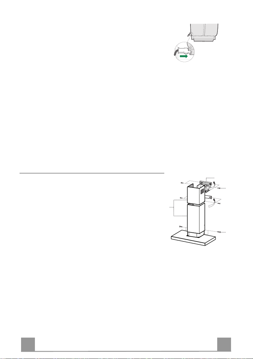
ELECTRICAL CONNECTION
12c
2.1
2.2
2
7.2.1
12c
• Connect the hood to the mains through a two-pole switch having a contact gap of at least 3 mm.
• Re move the grease filters (see paragraph Maintenance) being
sure that the conn ector of the feeding cable is correctly inserted
in the socket placed on th e side of the fan.
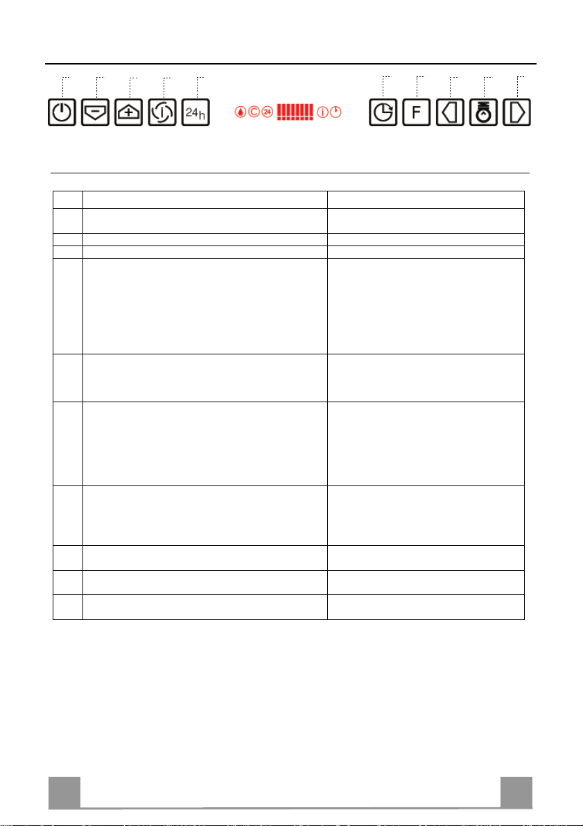
Flue assembly
Upper exhaust flue
• Slightly widen the two sides of the upper flue and hook them
behind the brackets 7.2.1, making sure that they are well
seated.
• Secure the sides to the brackets by using the 4 screws 12c (2,9
x 9,5) supplied.
• Make sure that the outlet of the extension s pieces is aligned
with the chimney outlets.
Lower ex haust flue
• Slightly widen the two sides of the flue and hook them between the upper flue and t he wall, making sure that they are
well seated.
• Fix the lower part laterally to the hood body by using the 2
screws 12c (2,9 x 9,5) supplied.
7
7
Page 8
EN
USE
Switches the extractor motor on and off at the latest
F
A
B
C
E
D
G
H
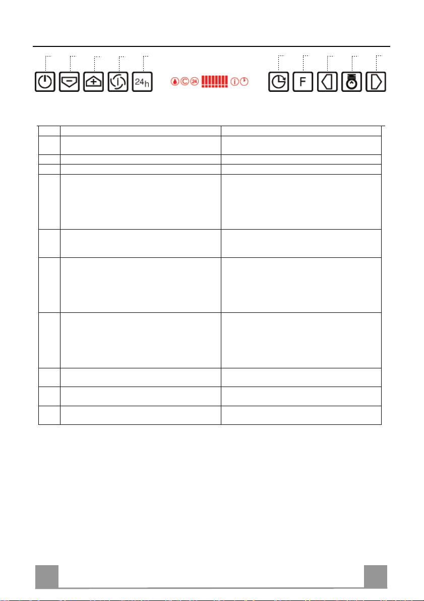
Control board
Key Function Display
A
selected speed
B Decreases the suction speed. The number of lit LEDS decreases.
C Increases the suction sp eed. The number of lit LEDS increases.
D By pressing this key it is possible to start the inten-
sive speed fr om any previously sele cted speed except the Delay-function and 24H-function. This
speed has been timed at 10 minutes. After that time
the system activates automatically the latest selected
speed. This function is suitable for cooking conditions when vapours and smells are at the utmost emission.
E By pressing this key it is possible to set up the motor
to a suction speed at 100 m
F By pressing this key it is possible to set the delayed
shutdown of the motor and the lighting to 30 minutes. This function is suitable for a complete elimination of resid ual cooking od ours. Funct ioning only
when the motor is on(n ot durin g th e 24H-fu nc tion or
intensive function). By pressing the key the function
is stopped
G By pressing this key for about 2 seconds it is possi-
ble to reset the filter saturation alarm
H By pressing this key the intensity of the lighting
system can be decreased.
I Switches on/off the li ghting syst em at the ma ximum
intensity.
L By pressing this key the intensity of the lighting
system can be increased.
3
/h .
Indicates the selected speed.
I flashes and the LEDS are all lit.
By pressing the key the function is
stopped.
24 ap pears and th e LEDS exti nguish on e
by one.
By pressing the key the function is
stopped
A flashing clock-symbol appears.
By pressing the key the function is
stopped
After 100 working hours a drop-symbol
appears. Metal grease filters have to be
washed.
After 200 working hours C appears.
Charcoal filters have to replaced.
Keyboard lock: it is p ossible to jam the keyboard when, for example, cleaning the glass. The
motor and lights are switched off.
By pressing the D-key (Intensive) for about 5 seconds the keyboard block can be activated or
deactivated. This function is confirmed by a Beep and by moving motor LEDS on display.
L
I
8
8
Page 9
EN
MAINTENANCE
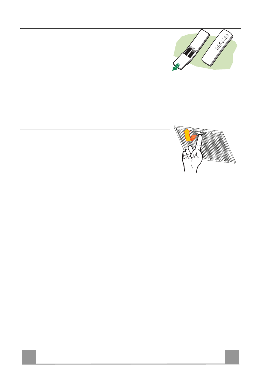
REMOTE CONTROL (OPTIONAL)
The appliance can be controlled using a remote control powered
by a 1.5 V carbon-zinc alkaline batteries of the standard LR03AAA type (not included).
• Do not place the remote co ntrol near to heat sources.
• Used batteries must be disposed of in the proper manner.
Metal grease filters
Metal filters can be washed also in a dish machine. They need to
be washed every time a drop-symbol appears in the display or at
least every two months. In case of very frequent use these have to
be washed even more often.
Alarm reset
• Press the G-key for at least 2 seconds.
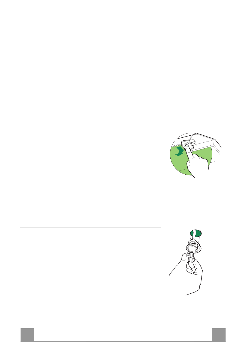
Cleaning
• Remove the filters one at a time holding them up with one
hand and pulling the handle downwards with the other hand at
the same time.
• Wash the filters. Pay attention not to bend them. Make sure
that filters are completely dry before putting them into their
seat. (a possible modification of the filter surface doesn’t influence its efficiency).
• Place the filters again into their seats and make sure that the
handle of the filter remains outside.
9
9
Page 10
EN 110
Charcoal filter (recycling version)
This filter cannot be washed or regenerated. It must be replaced when the C appears on the
display or at least once every 4 months. The filter saturation alarm has to be activated already
before.
Activation of the alarm signal
• In the recycling version hoods the filter saturation alarm must be activated during the installation or later.
• Switch off the hood and the lights.
• Press the E-key for about 5 seconds until the last two segments of the motor LEDS are lit on
the display.
• By releasing the E-key the clock icon starts to flash.
• Within 3 seconds press the D-key to activate/ deactivate charcoal filter saturation alarm.
• C-symbol lit - charcoal filter saturation alarm ACTIVATED.
• C-symbol unlit - charcoal filter saturation alarm DEACTIVATED.
SUBSTITUTION OF TH E CHARCOAL FILTER
Alarm reset
• Switch off the motor and the lighting system.
• Press the G-key for at least 2 seconds.
Substitution of the filter
• Remove the metal grease filters.
• Remove the charcoal filter as indicated in the picture.
• Place the filter again into its seat.
• Place again the metal grease filters into their place.
Lighting
LIGHT REPLACEMENT
20 W halogen light.
• Remove the 2 screws fixing the Lighting support, and pull it
out of from the Hood.
• Extract the lamp from the Support.
• Replace with another of the same type, making sure that the
two pins are properly inserted in the lamp holder socket holes.
• Refit the Support, fixing it in place with the two screws removed as above.
Page 11

IT 111
CONSIGLI E SUGGERIMENTI
Questo libretto di istruzioni per l'uso è previsto per più versioni dell' appare
c
chio.
650 mm min.
É possibile che siano descritti singoli particolari della dotazione, che non riguardano il Vostro apparec c hio.
INSTALLAZIONE
• Il produttore declina qualsiasi responsabilità per danni dovuti ad installazione non
corretta o non confor me alle regole d ell’art e.
• La distanza minima di sicurezza tra il Piano di cottura e la Cappa deve essere di
650 mm, (alcuni modelli possono esser e installati ad un’alt ezza inferiore, fare riferimento ai paragrafi i ngo mbro e i nst al laz ione) .
• Verificare che la tensione di rete corrisponda a quella riportata nella targhetta
posta all’interno della Cappa.
• Pe r Appare cchi in C lasse I
sca un corretto sc ar ic o a ter ra.
• Collegare la Cappa all’uscita dell’aria aspirata con tubazione di diametro pari o
superiore a 120 mm. Il percorso della tubazione deve essere il più breve possibile.
• Non collegare la Cappa a condotti di scarico dei fumi prodotti da combustione
(caldaie, caminet ti , ec c.) .
• Nel caso in cui nella stanza vengano utilizzati sia la Cappa che apparecchi non
azionati da energia elettrica (ad esempio apparecchi utilizzatori di gas), si deve
provvedere ad una aerazione sufficiente dell’ambiente. Se la cucina ne fosse
sprovvista, praticare un’apertura che comunichi con l’esterno, per garantire il richiamo d’aria pulita.
USO
• La Cappa è stata progettata esclusivamente per uso domestico, per abbattere gli
odori della cucina.
• Non fare mai uso improprio del la Cap pa.
• Non lasciare fiamme liber e a for te i ntens it à sott o la Cappa i n funz i one.
• Regolare sempre le fiamme in modo da evitare una evidente fuoriuscita laterale
delle stesse ri spet t o al fondo dell e p entol e.
• Controllare le friggit r ici durant e l’ us o: l ’ol io surr isc aldat o potr ebb e inf iammar s i.
• Non preparare alimenti fl ambè sot to l a c appa da cuc i na; per ic olo d'i nc endi o.
• Que sto appare cchio n on deve esse re utiliz zato da person e (bambini inclusi) con
ridotte capacità psichiche, sensoriali o mentali, oppure da persone senza esperienza e conoscenza, a meno che non siano controllati o istruiti all’uso
dell’apparecchio da person e r esponsabili della loro sicurezza.
• I bambini devono essere supervisionati per assicurarsi che non giochino con
l’apparecchio.
MANUTENZIONE
• Prima di procedere a qualsiasi operazione di manutenzione, disinserire la Cappa
togliendo la spina elettrica o spegnendo l’interruttore generale.
• Effettuare una scrupolosa e tempestiva manutenzione dei Filtri secondo gli intervalli consigliati (Rischio di incendio).
• Per la pulizia delle su pe rfici d e lla C a ppa è suffi cie n te u tiliz za re u n pa nn o umido e
detersivo liqui do neutr o.
a
accertarsi ch e l’imp ianto e lettrico dome stico ga ranti-
Il simbolo sul prodotto o sulla confezione indica che il prodotto non deve essere considerato
come un nor m ale rifiuto domes ti c o , m a d eve essere portat o n el p unto di raccolta a ppropriato per
il ricicl aggi o di a ppar ec c hi atur e el et tri che e d el et tro nic he. P r ovv edendo a smaltire questo prodotto in modo appropriato, si contribuisce a evitare potenziali conseguenze negative per l’ambiente
e per la salute, che potrebbero derivare da uno smaltimento inadeguato del prodotto. Per informazioni più dettagliate sul riciclaggio di questo prodotto, contattare l’ufficio comunale, il servizio
locale di smaltimento rifiut i o il negozio in cui è stato acqu istat o il prodot to .
Page 12
IT 112
CARATTERISTICHE
Ingombro
6341126
81
540
60
898
300
150
108 259
485
max. 1000
min. 670
260
Componenti
Rif. Q.tà Componenti di Prodotto
1 1 Corpo Cappa completo di: Comandi, Luce, Gruppo
Ventilatore, Filtri
2 1 Camino Teles copico formato da:
2.1 1 Camino Superiore
2.2 1 Camino Inferiore
9 1 Flangia di Riduzione ø 150-120 mm
14.1 2 Prolunga Raccordo Usc ita Aria
15 1 Raccordo Uscita Aria
Rif. Q.tà Componenti di Installazione
7.2.1 2 Staffe Fissaggi o Cami no Su periore
7.3 1 Staffa Sostegno Raccordo
11 8 Tasselli
12a 8 Viti 4,2 x 44,4
12c 6 Viti 2,9 x 9,5
Q.tà Documentazione
1 Libretto Istruzioni
650 min.
15
14.1
7.3
9
2.1
2
2.2
1
12a
7.2.1 11
12c
11
12a
Page 13
IT 113
INSTALLAZIONE
Foratura Parete e Fissaggio Staffe
1÷2
7.3
7.2.1
11
12a
116
116
X
320
650 min.
Tracciare sulla Parete:
• una linea Verticale fino al soffitto o al limite superiore, al centro della zona prevista per il
montaggio della Cappa;
• una linea Orizzon tale a: 650 mm min. sopra il Piano di Cottura.
• Appoggiare come indicat o l a Staffa 7.2.1 a 1-2 mm dal soffitto o dal limite superiore, allineando il suo centro (intagli) sulla linea Verticale di riferimento.
• Segnare i centri dei Fori della Staffa.
• Appoggiare come indicato la Staffa 7.2.1 a X mm sott o la pri ma staffa (X = altezza Camino
Superiore in dotazione), allineando il suo centro (intagli) sulla linea Verticale di riferimento.
• Segnare i centri dei Fori della Staffa.
• Segnare come indicato, un punto di riferimento a 116 mm dalla linea Verticale di riferimento, e 320 mm sopra la linea Orizzontale di riferimento.
• Ripetere questa operazione dalla parte opposta.
• Forare ø 8 mm i punti segnati.
• Inserire i tasselli 11 nei fori.
• Fissare la Staffa inferiore 7.2.1 utilizzando le Viti 12a (4,2 x 44,4 ) in dotazione.
• Fissare insieme la Staffa superiore 7.2.1 e la Staffa sostegno raccordo 7.3 utilizzando le 2
viti 12a (4,2 x 44,4) in dotazione.
• Avvitare 2 Viti 12a (4,2 x 44,4) in dotazione nei fori per il fissaggio del corpo Cappa, lasciando uno spazio di 5-6 mm fra la parete e la testa della vite.
Page 14

IT 114
Montaggio Corpo Cappa
9
ø 120ø 150
ø 150
15
14.1
7.3
• Prima di agganciare il Corpo Cappa, serrare le 2 Viti Vr situate sui
punti di aggancio de l Corpo Cappa.
• Agganciare il Corpo Cappa alle Viti 12a.
• Serrare definitivamente le Viti 12a di supporto.
• Agire sulle Viti Vr per livellare il Corpo Cappa.
• Nel caso si ritenga opportuno è possibile assicurare la cappa al muro
per mezzo di altre viti con tassello, posizionabili dal
cappa
.
l’interno del corpo
Connessioni
USCITA ARIA VERSIONE ASPIRANTE
Per installazione in Versione Aspirante collegare la Cappa alla
tubazione di uscita per mezzo di un tubo rigido o flessibile di
ø150 o 120 mm, la cui scelta è lasciata all'installatore.
• Per collegamento con tubo ø120 mm, inserire la Flangia di riduzione 9 sull’Uscita del Corpo Cappa.
• Fissare il tubo con adeguate fascette stringitubo. Il materiale
occorrente non è in dotazione.
• Togliere eventuali Filtri Antiodore al Carbone attivo.
Vr
12a
USCITA ARIA VERSIONE FILTRANTE
• Inserire lateralmente le Prolunghe Racco rdo 14.1 sul Raccordo
15.
• Inserire il Racco rdo 15 nella Staffa di Sostegno 7.3 fissandolo
con una Vite.
• Assicurarsi che l’uscita delle Prolunghe Raccordo 14.1 risulti
in corrispondenza delle bocchette del Camino sia in orizzontale
che in verticale.
• Co llegare il Raccordo 15 all’Uscita del Corpo Cappa per mezzo di un tubo rigido o flessibile di ø150 mm, la cui scelta è lasciata all'installatore.
• Assicurarsi della presenza del Filtro Antiodore al Carbone attivo.
Page 15

IT 115
CONNESSIONE ELETTRICA
12c
2.1
2.2
2
7.2.1
12c
• Collegare la Cappa all’Alimentazione di Rete interponendo un
Interruttore bipolare con apertura dei contatti di almeno 3 mm.
• Rimuovere i Filtri antigrasso (vedi par. “Manutenzione”) e assicurarsi che il connettore del Cavo di alimentazione sia correttamente inserito nella presa dell’Aspiratore
Montaggio Camino
Camino superiore
• Allargare leggermente le due falde laterali, agganciarle dietro
le Staffe 7.2.1 e richiuderle fino a battuta.
• Fissare lateralmente alle Staffe con 4 Viti 12c (2,9 x 9,5) in
dotazione.
• Assicurarsi che l’uscita delle Prolunghe Raccordo risulti in corrispondenza delle bocc hette de l C am i no.
Camino inferiore
• Allargare leggermente le due falde laterali del Camino, agganciarle tra il Camino superiore e la parete e richiuderle fino a
battuta.
• Fissare lateralmente la parte inferiore al Corpo Cappa, con 2
Viti 12c (2,9 x 9,5) in dotazione.
Page 16
IT 116
USO
F
A
B
C
E
D
Quadro comandi
Tasto Funzione Display
A Accende e spegne il motore di aspirazione
Visualizza la velocità impostata.
all’ultima velocità utilizzata.
B Decrementa la velocità di eserc izio. Diminuisc on o i segmenti accesi.
C Incrementa la velocità di eserci zio. Aumentano i s egmenti accesi.
D Attiva la velocità intensiva da qualsiasi velo-
cità ad eccezi one del Delay e d el 24H, tale velocità è temporizzata a 10 minuti, al termine
Lampeggia I e i segmenti sul Display sono tutti
accesi.
Si disattiva premendo il Tasto.
del tempo il sistema ritorna alla velocità precedentemente impostata. Adatta a fronteggiare le
massime emissioni di fumi di cottura.
E Attiva il motore ad una velocità che consente
un’aspirazion e di 100 m
3
/h per 10 minuti ogni
ora, terminati il motore si ferma.
F Attiva lo spegnimento automatico ritardato di
30’. Adatto per completare l’eliminazione di
odori residui. Attivabile solo a motore acceso
Visualizza 24 e i segmenti sul Display da tutti
accesi si spengono uno al l a vo l ta cicl i cam e n te.
Si disattiva premendo il Tasto.
Visualizza i l simbolo d i un Orologio che lam-
peggia.
Si disattiva premendo il Tasto.
ad una Velocità diversa da 24H e Intensiva, si
disattiva premendo il tasto o spegnendo il motore.
G Effettua il Reset dell’alla rme satura zione Filtri
premendo il Tasto per circa 2 Secondi.
Dopo 100 ore di Funzionamento Visualizza il
simbolo Goccia per segnalare la saturazione
dei Filtri Metallici.
Dopo 200 ore di Funzionamento Visualizza C
per segnalare la satu razi one d ei Filt ri al C arbo-
ne Attivo.
H Decrementa l’intensità di Illuminazione ad
ogni pressi one del Tasto in modo ciclico.
I Accende e spegne l’impianto di illuminazione
alla massi ma i ntensità.
L Incremen ta l’i nten sità di Illumin azione ad ogni
pressione del Tasto in modo ciclico.
Comando Blocco Tastiera: è possibile bloccare la tastiera, ad esempio per effettuare la pulizia
della superficie in Vetro, quando la Cappa ha il Motore e le Luci spente.
Premendo per circa 5 Secondi il tasto D (Intensiva) si può abilitare o disabilitare il Blocco Tastiera che è sempre confermato con un Beep e un’animazione sulla barra motore del display.
G
I
H
L
Page 17

IT 117
MANUTENZIONE
TELECOMANDO (OPZIONALE)
Questo apparecchio può essere c omandato per mezzo di un tel ecomando, alimentato con pile alcaline zinco-carbone da 1,5 V del
tipo standard LR03-AAA (non incluse).
• Non riporre il telecomando in prossimità di fonti di calore.
• Non disperdere le pile nell’ambiente, depositarle negli appositi
contenitori.
Filtri antigrasso metallici
Sono lavabili anche in lavastoviglie, e necessitano di essere lavati
quando sul display appare il simbolo Goccia o almeno ogni 2
mesi circa di utilizzo o più frequentemente, per un uso particolarmente intenso.
Reset del segnale di allarme
• Premere il tasto G per almeno 2 Secondi.
Pulizia Filtri
• Togliere i Filtri uno alla volta,sostenendoli con una mano mentre con l’altra si tira la leva verso il basso.
• Lavare i Filtri evitando di piegarli, e lasciarli asciugare prima
di rimontarli. (Un’event uale cambiamento del colore dell a superficie del filtro, che potrebbe verificarsi nel tempo, non pregiudica assolutamente l’efficienza dello stesso.)
• Rimontarli facendo attenzione a mantenere la maniglia verso la
parte visibile esterna.
Page 18

IT 118
Filtri antiodore al Carbone attivo (Versione Filtrante)
Non è lavabile e non è rigenerabile, va sostituito quando sul display appare il simbolo C o almeno ogni 4 mesi. La segnalazione di Allarme va preventivamente attivata.
Attivazione del segnale di allarme
• Nelle Cappe in Versione Filtrante, la segnalazione di Allarme saturazione Filtri va attivata al
momento dell’installazione o successivamente.
• Spegnere le Luci e il Motore di aspirazione.
• Premere il tasto E per circa 5 Sec. fino all’accensione degli ultimi due segmenti e di tutta la
linea puntinata della barra Motore sul Display.
• Rilasciare il tasto E, l’icona “Orologio” inizia a lampeggiare.
• Entro 3 secondi premere il Tasto D per abilitazione / disabilitazione Filtri C.A.
• Accensione del simbolo C Allarme saturazione Filtro C.A. ATTIVATO
• Spegnimento del simbolo C Allarme saturazione Filtro C.A. DISATTIVATO
SOSTITUZIONE FILTRO ANTIODORE AL CARBONE ATTIVO
Reset del segnale di allarme
• Spegnere le Luci e il Motore di aspirazione.
• Premere il tasto G per almeno 2 Secondi.
Sostituzione Filtro
• Togliere i Filtri antigrasso metallici.
• Rimuovere il Filtro antiodore al Carbone attivo saturo, come
indicato in figura.
• Montare il nuovo Filtro agganciandolo nella sua sede.
• Rimontare i Filtri antigrasso metallici.
Illuminazione
SOSTITUZIONE LAMPADE
Lampade alogene da 20 W.
• Togliere le due viti che fissano il Supporto illuminazione e sfilarlo dalla Cappa.
• Estrarre la Lampada dal Supporto.
• Sostituirla con una nuova di uguali caratteristiche, facendo attenzione di inserire correttamente i due spinotti nella sede del
Supporto.
• Rimontare il Supporto fissandola con le due Viti precedentemente tolte.
Page 19

FR 119
CONSEILS ET SUGGESTIONS
650 mm min.
La présente notice d'emploi vaut pour plusieurs versions de l'appareil. Elle peut conte-
nir des descriptions d'accessoir es ne fi gurant pas dan s votr e apparei l.
INSTALLATION
• Le fabricant décline toute responsabilité en cas de dommage dû à un e in st alla tion non
correcte ou non conforme aux règles de l ’ art.
• La distance minimale de sécurité entre le plan de cuisson et la hotte doit être de 650
mm au moins (certains modèles peuvent être installés à une hauteur inférieure : se reporter aux paragraphes « Encombrem ent » et « Instal lati on »).
• Vérifier que la tension du secteur correspond à la valeur qui figure sur la plaquette
apposée à l’intérieur de la hotte.
• Pour les Appareils appartenant à la Ière Classe, veiller à ce que la mise à la terre de
l’installation électrique domestique ait été effectuée conformément aux normes en vigueur.
• Connecter la hotte à la sort ie d’air aspiré à l’ aide d’une tuyauterie d’un diamètre égal ou
supérieur à 120 mm. Le parcours de la tuyaut eri e doit être le plus court possibl e.
• Ne pas connecter la hotte à des conduites d’évacuation de fumées issues d’une combustion tel que (Chaudière, chemi née, et c…).
• Si vous utilisez des appareils qui ne fonctionnent pas à l’électricité dans la pièce ou est
installée la hotte (par exemple: des appareils fonctionnant au gaz), vous devez prévoir
une aération suffisante du milieu. Si la cuisine en est dépourvue, pratiquez une ouverture qui communique avec l’ext érieur pour garant ir l’infil trati on de l’ai r pur.
UTILISATION
• La hotte a été conçue exclusivement pour l’usage domestique, dans le but d’éliminer
les odeurs de la cuisine.
• Ne jamais utiliser abusivement la hotte.
• Ne pas laisser les flammes libres à forte intensité quand la hotte est en service.
• Toujours régler les flammes de manière à éviter toute sortie latérale de ces dernières
par rapport au fond des marmites.
• Contrôler les friteuses lors de l’utilisati on car l’huile sur chauff ée pourrai t s’ enfl ammer.
• Ne pas préparer d’aliments flambés sous la hotte de cuisi ne : risque d’ incendi e
• Cet appareil ne doit pas être utilisé par des personnes (y compris les enfants) ayant
des capacités psychiques, sensorielles ou mentales réduites, ni par des personnes
n’ayant pas l’expérience et la connaissance de ce type d’appareils, à moins d'être so us
le contrôle et la formation de personn es respo nsables de l eur sécuri té.
• Les enfants doivent être surveillés pour s'assurer qu'ils ne jouent pas avec l'appareil.
ENTRETIEN
• Avant de procéder à toute opération d’entretien, ret irer la hotte en retirant la fiche ou en
actionnant l’interrupteur général.
• Effectuer un entretien scrupuleux et en temps dû des Filtres, à la cadence conseillée
(Risque d’incendie).
• Pour le nettoyage des surfaces de la hotte, il suffit d’utiliser un chiffon humide et détersif liquide neutr e.
Le symbole sur le produit ou son emballage indique que ce produit ne peut être traité comme
déchet ménager. Il doit plutôt être remis au point de ramassage concerné, se chargeant du recyclage du matériel électrique et électronique. En vous assurant que ce produit est éliminé correctement, vous favorisez la prévention des conséquences négatives pour l’environnement et la santé
humaine qui, sinon, seraient le résultat d’un traitement inapproprié des déchets de ce produit. Pour
obtenir plus de détails sur le recyclage de ce produit, veuillez prendre contact avec le bureau municipal de votre région, votre service d’élimination des déchets ménagers ou le magasin où vous avez
acheté le produit.
Page 20

FR 220
CARACTERISTIQUES
Encombrement
6341126
81
540
60
898
300
150
108 259
485
max. 1000
min. 670
260
Composants
Réf. Q.té Composants de Produit
1 1 Corps Hotte équ ipé de:Command es, Lumière, Groupe
Ventilateur,Filtres
2 1 Cheminée Télescopique formée de :
2.1 1 Cheminée Supérieure
2.2 1 Cheminée Inférieure
9 1 Flasque de Réduction ø 150-120 mm
14.1 2 Rallonge Raccord Sortie Air
15 1 Raccord Sortie Air
Réf. Q.té Composants pour l ’installation
7.2.1 2 Brides Fixation Cheminée Supérieure
7.3 1 Bride Support Raccord
11 8 Chevilles
12a 8 Vis 4,2 x 44,4
12c 6 Vis 2,9 x 9,5
Q.té Documentation
1 Manuel d’instructions
650 min.
15
14.1
7.3
9
2.1
2
2.2
1
12a
7.2.1 11
12c
11
12a
Page 21

FR 221
INSTALLATION
Perçage Paroi et Fixation Brides
1÷2
7.2.1
7.3
X
116
116
11
12a
320
650 min.
Tracer sur la paroi:
• une ligne verticale allant jusqu’au plafond ou à la limite supérieure, au centre de la zone
prévue pour le montage de la hotte;
• une ligne horizontale à 650 mm min. au-dessus du plan de cuisson.
• Poser comme indiqué une bride 7.2.1 sur la paroi à 1-2 mm du plafond ou de la limite supérieure, en alignant son centre (découpes) sur la ligne verticale de repère.
• Marquer les centres des trous rainurés de la bride.
• Poser comme indiqué la bride 7.2.1 à X mm sous la première bride (X = hauteur cheminée
supérieure fournie), en align ant son centre (découpes) sur la ligne verticale de repère.
• Marquer les centres des trous rainurés de la bride.
• Marquer comme indiqué, un point de référence à 116 mm de la ligne verticale de repère, et
320 mm au-dessus de la ligne horizontale de repère.
• Répéter cette opération sur le côté opposé.
• Percer de ø 8 mm tous les points marqués.
• Insérer les chevilles 11 dans les trous.
• Fixer la bride inférieure 7.2.1 en utilisant les vis 12a (4,2 x 44,4) fournies.
• Fixer ensemble la bride supérieure 7.2.1 et le support 7.3 en utilisant les vis 12a (4,2 x 44,4)
fournies.
• Visser les 2 vis 12a (4,2 x 44,4) fournies dans les trous de fixation du corps hotte, en laissant
un le espace de 5-6 mm entre le mur et la tête de la vis
Page 22

FR 222
Montage Corps Hotte
9
ø 120ø 150
ø 150
15
14.1
7.3
• Avant d’accrocher le corps hotte, serrer les deux vis Vr situées sur les
points d’accrochage du corps hotte.
• Accrocher le corps hotte aux vis 12a prévues à cet effet.
• Serrer définitivement les vis 12a de support.
• Agir sur les vis Vr pour niveler le corps hotte.
• Si cela est jugé nécessaire, il est possible de fixer la hotte au mur au
moyen de chevilles et vis supplémentaires qu’il faudra placer de
l’intérieur du co r ps de la hotte.
Branchements
SORTIE AIR VERSION ASPIRANTE
En cas d’installation en version aspirante, brancher la hotte à la
tuyauterie de sortie via un tube rigide ou flexible de ø 150 ou 120
mm, au choix de l’installateur.
• En cas de branchement avec un tu be de ø120 mm, insérer le
flasque de réduction 9 sur la sortie du corps de la hotte.
• Fixer le tube par des colliers appropriés. Le matériau nécessaire n’est pas fourni.
• Retirer les éventuels filtres anti-odeur au charbon actif.
SORTIE AIR VERSION FILTRANTE
Vr
12a
• Insérer latéralement les rallonges raccord 14.1 sur le raccord
15.
• Placer le raccord 15 dans l’étrier de soutien 7.3 en le fixant
avec une vis.
• S’assurer que la sortie des rallonges racco rd 14.1 se trouve au
niveau des bouches de la cheminée aussi bien en horizontal
qu’en vertical.
• Bran cher le raccord 15 à la sortie du corps de la hotte avec un
tube rigide ou flexible de ø 150 mm, selon le choix de
l’installateur.
• S’assurer de la présence des filtres anti-odeur au charbon actif.
Page 23

FR 223
BRANCHEMENT ELECTRIQUE
12c
2.1
2.2
2
7.2.1
12c
• Brancher la hotte sur le secteur en interpo sant un interrupteur
bipolaire avec ouvertu re des contacts d’au moins 3 mm.
• Enlever les filtres à graisse (voir § "Entretien") et s'assurer que
le connecteur du câbl e d'al imentati on so it bien bran ché dan s la
prise du diffuseur.
Montage Cheminée
Cheminée supérieure
• Elargir légèrement les deux bords latériaux, et les accrocher
derrières les brides 7.2.1 ; refermer
jusqu’à la butée.
• Fixer latéralement aux brides à l’aide des 4 vis
12c fournies.
• S’assurer que la sortie des rallonges raccord se trouve au niveau des bouches de la cheminée.
Cheminée inférieure
• Elargir légèrement les deux bords latériaux de la Cheminée et
les accrocher entre la Cheminée sup éri eure et la paroi; refermer
jusqu’à la butée.
• Fixer latéralement la partie inférieure au corps
hotte, à l’aide des deux 2 vis 12c fournies.
Page 24

FR 224
UTILISATION
F
A
B
C
E
D
G
H
Tableau des commandes
Touche Fonction Afficheur
A Allume et éteint le moteur d’aspiration à la der-
La vitesse choisie s’affiche.
nière vitesse utilisée
B La vitesse de service diminue. Les segments allumés diminuent.
C La vitesse de service augmente. Les segments allumés augmentent.
D Active la vitesse intensive à partir de n’importe
quelle vitesse, à l’exception des fonctions Retard
et 24H. Cette vitesse est programmée pour durer
I clignote et les segments affichés sont
tous allumés.
Appuyer sur la touche pour désactiver.
10 minutes, après quoi le système retourne à la
vitesse réglée a u pr éalab le. Apt e à faire fa ce à u ne
quantité maximale de fumées de cuisson.
E Active le moteur à une vitesse permettant une aspi-
ration de 100 m
3
/h pendant 10 minutes chaque
heure, puis le moteur s’arrête.
24 s’affiche et les segments aff ichés qui
étaient t ous allumés s’éteignen t un à un
de manière cyclique.
Appuyer sur la touche pour désactiver.
F Active l’arrêt automatique retardé de 30 minutes.
Sert à éliminer complètement toute odeur résiduelle. S’active quand le moteur allumé à une
Le symbole d’une horloge qui clignote
s’affiche.
Appuyer sur la touche pour désactiver.
vitesse différente de 24H et Intensive ; appuyer sur
la touche ou éteindre le moteur pour désactiver
cette fonction.
G Rétablit l’alarme de saturation des fi ltres en ap-
puyant sur la touche pendant environ 2 secondes.
Le symbole Goutte s’affiche après 100
heures de service pour signaler la satura-
tion des filtres métalliques.
C s’affiche après 200 heures de service
pour signaler la saturation des filtres au
charbon actif.
H L’intensité de l’éclairage diminue de façon cycli-
que chaque fois que l’on appuie sur la touche.
I Allume et éteint l’éclairage à intensité maximale.
L L’intensité de l’éclairage augmente de façon cycli-
que chaque fois que l’on appuie sur la touche.
Commande de blocage du Clavier : il est possible de bloquer le clavier, par exemple pour effectuer le nettoyage des surfaces en verre quand le moteur et l’éclairage de la hotte sont
éteints.
Appuyer sur la touche D (intensive) pendant env. 5 secondes pour activer ou désactiver le blocage du clavier ; cette fonction est toujours confirmée par un bip sonore et une animation qui
s’affiche sur la barre du moteur.
L
I
Page 25

FR 225
ENTRETIEN
TELECOMMANDE (FOURNIE SUR DEMANDE)
Il est possible de commander cet appareil au moyen d’une télécommande, alimentée avec des piles alcalines zinc-charbon 1,5 V
du type standard LR03-AAA (non compris).
• Ne pas ranger la télécommande à proximité de sources de chaleur.
• Ne pas jeter les piles; il faut les déposer dans les récipients de
récolte spécialement prévus à cet effet.
Filtres à graisse métalliques
Ils sont lavables même en lave-vaisselle et doivent être lavés
chaque fois que le symbol e Goutte s’affiche ou au moins tous les
2 mois environ, voire plus souvent, en cas d’utilisation particulièrement intensive.
Rétablissement du signal d’alarme
• Appuyer sur la touche G pendant au moins 2 secondes.
Nettoyage des filtres
• Enlevez les filtres l’un après l’autre en les soutenant avec une
main et en tirant en même temps la poignée vers le bas avec
l’autre main.
• Laver les filtres en évitant de les plier, et les faire sécher avant
de les remonter. (Tout change me nt d e cou leu r sur l a surface du
filtre, susceptible de se produire avec le temps, ne nuit en rien
à l’efficacité de ce dernier.)
• Remonter les filtres en faisant attention de tenir la poignée vers
la partie externe visible.
Page 26

FR 226
Filtres anti-odeur au charbon actif (version filtrante)
Il ne peut être ni lavé ni récupéré, il faut le changer quand le symbole C s’affiche ou au moins
tous les 4 mois. Il faut tout d’abord activer le signal d’alarme.
Activation du signal d’alarme
• Pour les hottes en version filtrante, l’alarme indiquant la saturation des filtres doit être activée au moment de l’installation ou ultérieurement.
• Éteindre les lumières et le moteur d’aspiration.
• Appuyer sur la touche E pendant 5 sec. environ, jusqu’à ce que les deux derniers segments
et toute la ligne en pointillés de la barre Moteur s’allument sur l’afficheur.
• Relâcher la touche E, l’i cône “Horloge” commencera à clignoter.
• Appuyer sur la touche D dans les 3 secondes qui s uivent pour activer/désactiver les filtres
au C.A.
• Le symbole C s’allu me : alarme de saturation du filtre au C.A. ACTIVÉE
• Le symbole C s'éteint : alarme de saturation du filtre au C.A. DÉSACTIVÉE
REMPLACEMENT DU FILTRE ANTI-ODEUR AU CHARBON ACTIF
Rétablissement du signal d’alarme
• Éteindre les lumières et le moteur d’aspiration.
• Appuyer sur la touche G pendant au moins 2 secondes.
Remplacement du Filtre
• Retirer les Filtres à graisse métalliques.
• Suivre les indications (A) pour retirer le filtre anti-odeur au
charbon actif saturé.
• Mettre le nouveau Filtre en l’accrochant bien en place.
• Remonter les Filtres à graisse métalliques.
Eclairage
REMPLACEMENT LAMPES
Lampe halogène de 20 W.
• Retirer les 2 Vis qui fixent le Support éclairage et ôter ce d ernier de la Hotte.
• Extraire la Lampe du Support.
• Re mplacer par un e nouvelle lampe possédant les mêmes caractéristiques, en veillant à ce que les deux fiches soient correctement insérées dans le logement de la Douille.
• Remonter le Support en le fixant à l’aide des deux Vis précédemment retirées.
Page 27

DE 227
EMPFEHLUNGEN UND HINWEISE
650 mm min.
Diese Gebrauchsanleitung gilt für mehrere Geräte-Ausführungen. Es ist möglich, dass
einzelne Ausstattungsmerkmale beschrieben sind, die nicht auf Ihr Gerät zutreffen.
MONTAGE
• Der Hersteller haftet nicht für Schäden, die auf eine fehlerhafte und unsachgemäße Montage zurückzuführen sind.
• Der minimale Sicherheitsabstand zwischen Kochmulde und Haube muss 650 mm betragen (einige Modelle können an einer geri ngeren Höhe i nstalli ert werden, bezi ehen Si e sich
dazu auf den Absatz Raumbedarf und Installation).
• Prüfen, ob die Netzspannung mit dem Wert auf dem im Haubeninneren angebrachten Schild übereinstimmt.
• Bei Geräten der Klasse I ist sicherzustellen, dass die elektrische Anlage des Wohnha uses
über eine vorschriftsmäßige Erdung verfügt.
• Das Anschlussrohr der Haube zur Luftaustrittsöffnung muss einen Durchmesser von 120
mm oder darüber aufweisen. Der Rohrverlauf muss so kurz wie möglich sein.
• Die Haube darf an keine Entlüftungsschächte angeschlossen werden, in die Verbrennungsgase (Heizkessel, Kamine usw.) geleitet werden.
• Werden im Raum außer der Dunstabzugshaube andere, nicht elektrisch betriebene (z.B.
gasbetriebene) Geräte verwendet, muss für eine ausreichende Belüftung gesorgt werden.
Sollte die Küche diesbezüglich nicht entsprechen, ist an einer Aussenwand eine Öffnung
anzubringen, die Frischluftzufuhr gewährleistet.
BEDIENUNG
• Die Dunstabzugshaube ist ausschließlich zum Einsatz im privaten Haushalt und zur
Beseitigung von Küchengerüchen vorgesehen.
• Unsachgemäßer Einsatz der Haube ist zu unterlassen.
• Große Flammen bei eingeschalteter Haube niemals unbedeckt lassen.
Acht ung ! Große Fl ammen be i eing esc haltet e r Haube niema ls un bedeck t lasse n.
• Die Intensivität der Flamme ist so zu regulieren, dass sie den Topfboden nicht überragt.
Achtung! Frittiergeräte müssen während des Gebrauchs stets beaufsichtigt wer-
den: Überhitztes Öl kann sich entzünden.
• Frittiergeräte müssen während des Gebrauchs stets beaufsichtigt werden: überhitztes Öl
kann sich entzünden.
• Keine flambierten Speisen unter der Abzugshaube zubereiten: Brandgef ahr.
• Dieses Gerät darf nicht von Personen, auch Kindern, mit verminderten psychischen, sensorischen und geistigern Fähigkeiten, oder von Personen ohne Erfahrung und K ennt nisse
benutzt werden, sofern sie nicht von für ihre Sicherheit verantwortlichen Personen beaufsichtigt und beim Gebrauch des Geräts angeleitet werden.
• Kinder dürfen sich nicht unbeaufsichtigt in der Nähe des Geräts aufhalten und auf keinen
Fall mit dem Gerät spielen.
WARTUNG
• Bevor Wartungsarbeiten durchgeführt werden, muss die Stromzufuhr zur Haube unterbrochen werden, indem der Stecker gezogen oder der Hauptschalter abgeschaltet wird.
• Bei der Filterwartung müssen die vom Hersteller empfohlenen Zeiträume zum Austauschen
der Filter genauestens eingehalten werden (Brandgefahr).
• Zur Reinigung der Haubenflächen Wir empfehlen ein feuchtes Tuch und ein mildes Flüssigreinigungsmittel.
• Bitte keine Reinigungsmittel mit Scheuermittel verwenden. Die Oberfläche wird damit
verkratzt.
Das Symbol auf dem Produkt oder seiner Verpackung weist darauf hin, dass dieses Produkt nich t als
normaler Haushaltsabfall zu behandeln ist, sondern an einem Samme lpunkt für das Recycling vo n elektrischen und elektronischen Geräten abgegeben werden muss. Durch Ihren Beitrag zum korrekten Entsorgen
dieses Produkts schützen Sie die Umwelt und die Gesundheit Ihrer Mitmenschen. Umwelt und Gesundheit
werden durch falsches Entsorgen gefährdet. Weitere Informationen über das Recycling dieses Produkts
erhalten Sie von Ihrem Rathaus, Ihrer Müllabfuhr oder dem Geschäft, in dem Sie das Produkt gekauft haben.
Page 28

DE 228
CHARAKTERISTIKEN
Platzbedarf
6341126
81
540
60
898
300
150
108 259
485
Komponenten
Pos. St. Produktkomponenten
1 1 Haubenkörper mit Schaltern, Beleuchtung, Gebläse-
gruppe, Filter
2 1 Teleskopkamin bestehend aus:
2.1 1 oberer Kaminteil
2.2 1 unterer Kaminteil
9 1 Reduzierflansch ø 150-120 mm
14.1 2 Verlängerung Luftaustritt-Anschlussstück
15 1 Luftaustritt-Anschlussstück
Pos. St. Montagekomponenten
7.2.1 2 Befestigungsbügel oberer Kaminteil
7.3 1 Bügel für Anschlusshalter
11 8 Dübel
12a 8 Schrauben 4,2 x 44,4
12c 6 Schrauben 2,9 x 9,5
St. Dokumentation
1 Bedienungsanleitung
min. 670
260
max. 1000
650 min.
15
14.1
7.3
9
2.1
2
2.2
1
12a
7.2.1 11
12c
11
12a
Page 29

DE 229
MONTAGE
Bohren der Befestigungslöcher und Fixieren der Befestigungsbügel
7.2.1
7.3
116
116
11
12a
650 min.
Achtung: Bitte beachten Sie bei der Montage das Gewicht der kompletten Haube. Die Tragfä-
higkeit der Decke oder alternativ der Trägerplatte für diese Zugbelastung muss vor der Montage geprüft und gegebenenfalls durch die Anbringung von geeigneten Befestigungs- oder
Stabilisierungselementen hergestellt werden. Kann eine hinreichende Tragfähigkeit nicht sichergestellt werden, ist von einer Montage abzusehen.
Nachstehende Linien an die Wand zeichnen:
• Eine vertikale Linie bis zur Decke oder oberen Begrenzung, und zwar in der Mitte des Bereiches,in dem die Haube montiert werden soll;
• Eine horizontale Linie: mit einem minimalen Abstand von 650 mm zur Kochfläche.
• Einen Bügel 7.2.1 zirka 1-2 mm unter der Decke oder oberen Begrenzung an die Wand le-
gen und seinen Mittelpunkt (Einschnitte) auf die vertikale Bezugslinie ausrichten.
• Die Mitte der beiden Bügellöcher an der Wand markieren.
• Den zweiten Bügel 7.2.1 an die Wand legen, wobei ein Abstand X mm vom oberen Bügel
einzuhalten ist (X = Höhe des jeweiligen oberen Kaminteils); den Mittelpunkt (Einschnitte)
auf die vertikale Bezugslinie ausrichten.
• Die Mitte der Bügellöcher an der Wand markieren.
• Wie beschrieben einen Bezugspunkt 116 mm von der vertikalen Bezugslinie und 320 mm
oberhalb der horizontalen Bezugslinie kennzeichnen.
• Gleichermaßen an der gegenüberliegenden Seite vorgehen.
• Mit einem Bohrer ø 8 mm die markierten Punkte bohren.
• Die Dübel 11 in die Bohrungen einfügen.
• Den unteren Bügel mit den mitgelieferten Schrauben 12a (4,2 x 44,4) fixieren.
• Den Bügel für Anschlusshalter mit den 2 mitgelieferten Schrauben 12a (4,2 x 44,4) auf den
oberen Bügel 7.2.1 befestigen.
• 2 der mitgelieferten Schrauben 12a(4,2 x 44,4)bei den Befestigungslöchern des Haubenkör-
pers einschrauben, wobei zwischen Wand und Schraubenkopf ein Freiraum von 5-6 mm zu
belassen ist.
1÷2
X
320
Page 30

DE 330
Montage des Haubenkörpers
9
ø 120ø 150
ø 150
15
14.1
7.3
• Bevor der Haubenkörper eingehakt wird, die 2 Schrauben Vr bei den
Haubenkörper-Anhakpunkten festziehen.
• Den Haubenkörpe r bei den Schrauben 12a einhängen.
• Die Halteschrauben 12a definitiv festziehen.
• Den Haubenkörper mit Hilfe der Schrauben Vr ausrichten.
• Die Haube kann bei Bedarf mit Hilfe weiterer Schrauben und Dübel
von innen an der Wand gesichert werden.
Anschluss der Abluftversion
Bei Abluftbetrieb kann die Haube vom Installateur wahlweise
mittels Rohr oder Schlauch (ø 150 oder 120 mm) an die Außenrohrleitung angeschlossen werden.
• Bei Verwendung eines Anschlussrohres ø 120 den Reduzierflansch 9 am Haubenaustritt anbringen.
• Das Rohr mit geeigneten Rohrschellen fixieren. Das hierzu
erforderliche Material wird nicht mitgeliefert.
• Eventuell vorhandene Aktivkohlefilter entnehmen.
Achtung! Alle Querschnittänderungen oder Richtu ngsän-
derungen de s Abluf tkan als red uzieren die Lei stung der Haube.
Vr
12a
Anschluss der Umluftversion
• Die Verl ängeru ngen 14.1 beim Anschluss 15 seitlich einfügen.
• Den Anschluss 15 am Haltebügel 7.3 einsetzen und mit einer
Schraube fixieren.
• Überpr üfen, ob die V erlängerungen 14.1 mit den entsprechenden Kaminstutzen sowohl horizontal wie auch vertikal übereinstimmen.
• Vom Installateur wahlweise mittels Rohr oder Schlauch (ø 150
mm), den Anschluss 15 am Haubenaustritt anbringen.
• Kontrollieren, ob der Aktivkohle-Geruchsfilter montiert ist.
Page 31

DE 331
Elektroanschluss
12c
2.1
2.2
2
7.2.1
12c
Vor der Installation die Netzspannung durch herausdrehen der
Sicherung oder ausschalten des Hauptschalters s tromlos machen.
• Bei Anschluss der Haube an das Stromnetz muss ein
zweipoliger Schalter mit einem Öffnungsweg von
mindestens 3 mm zwischengeschaltet werden.
• Entfernen Sie die Fettfilter (s. Abschnitt „Wartung“) und
versichern Sie sich, daß die Kabel verbindung in die Steckdose des Gebläses einwandfrei eingesteckt wird.
Achtung: Das Gerät nur an die Netzspannung die im Typen-
schild angegeben ist anschließen.
Kaminmontage
Oberer Kaminteil
• Die beiden seitlichen Schenkel leicht auseinanderbiegen, hinter
den Bügeln 7.2.1 einhängen und bis zum Anschlag wieder
schließen.
• Bei den Bügeln 7.2.1 mit Hilfe der 4 mitgelieferten Schrauben
12c fixieren.
• Überprüfen, ob die Verlängerungen mit den entsprechenden
Kaminstutzen überein stimmen.
Unterer Kaminteil
• Die beiden seitlichen Schenkel des Kaminteils leicht auseinander biegen, zwischen dem oberen Kaminteil und der Wand
einhängen und bis zum Anschlag wieder schließen.
• Den unteren Teil seitlich am Haubenkörper mit 2 der mitgelieferten Schrauben 12c fixieren.
Page 32

DE 332
BEDIENUNG
F
A
B
C
E
D
Bedienfeld
Taste Funktion Display
A Schaltet den Gebläsemotor in der zuletzt ver-
Zeigt die eingestellte Gebläsestufe an.
wendeten Gebläsestufe ein und aus.
B Verringert die laufende Gebläsestufe. Die leuchtenden Segmente nehmen ab.
C Steigert die laufende Gebläsestufe. Die leuchtenden Segmente nehmen zu.
D Aktiviert die Intensivstufe bei jeder Geschwin-
digkeit, mit Ausnahme der Funktionen Delay
und 24H. Die Intensivstufe ist auf 10 Minuten
begrenzt. Da nach kehrt das System zu r zuvor
I blinkt und alle Segmente auf dem Display
leuchten.
Lässt sich durch Drücken der Taste ausschal-
ten.
eingestellt en Gebläsest ufe zurück. Zu m Beseitigen sehr starker Küchendünste geeignet.
E Schaltet den Motor auf einer Gebläsestufe ein,
die pro Stunde ein zehnminütiges Absaugen
von 100 m3/h erlaubt. Danach schaltet sich der
Motor aus.
Zeigt 24 an und alle auf dem Disp lay angezeig-
ten Segmente erlöschen allmählich nacheinan-
der.
Lässt sich durch Drücken der Taste ausschal-
ten.
F Aktiviert das automatische Abschalten nach 30
Minuten. Zum Beseitigen von verbliebenen
Küchendünsten geeignet. Lässt sich nur bei
Zeigt das Symbol einer blinkenden Uhr an.
Lässt sich durch Drücken der Taste ausschal-
ten.
eingeschaltetem Motor und nicht bei Intensivstufe oder 24-Stunden-Funktion aktivieren.
Lässt sich durch Drücken der Taste oder durch
Ausschalten des Motors deaktivieren.
G Durch ca. 2 Sekunden langes Drücken der Tas-
te wird die Filtersättigungsanzeige rückge-
stellt.
Nach 100 Betriebsstunden zeigt das Symbol
Tropfen die Sättigung der Metallfilter an.
Nach 200 Betriebsstunden zeigt C die Sätti-
gung der Aktivkohlefilter an.
H Verringert die Intensität der Beleuchtung zyk-
lisch mit jedem Drücken der Taste.
I Schaltet die Beleuchtungsanlage auf höchster
Intensitätsstufe ein und aus.
L Steigert die Intensität der Beleuchtung zyklisch
mit jedem Drücken der Taste.
Steuerbefehl Tastatursperre: Die Tastatur lässt sich, z.B. zur Rei nigung der Sch eiben, sperren ,
wenn Motor und Beleuchtung der Haube ausgeschaltet sind.
Zum Aktivieren oder Deaktivieren der Tastatursperre die Taste D (Intensivstufe) ca. 5 Sekunden lang drücken. Der Vorgang wird immer durch einen Piepton und die Motorbalkenanzeige
auf dem Display bestätigt.
G
I
H
L
Page 33

DE 333
WARTUNG
FERNBEDIENUNG (OPTION)
Dieses Gerät kann mit einer Fernbedienung gesteuert werden,
welche mit alkalischen Zink-Kohle-Batterien 1,5 V des Standardtyps LR03-AAA versorgt wird (nicht enthalten).
• Die Fernbedienung nicht in die Nähe von Hitzequellen legen.
• Batterien müssen vorschriftsmäßig entsorgt werden.
Metallfettfilter
Die Filter können im Geschirrspüler gereinigt werden und sollten
gereinigt werden, wenn das Symbol Tropfen auf dem Display
erscheint bzw. mindestens ca. alle 2 Monate oder bei sehr intensivem Einsatz auch häu figer.
Rückstellen der Sättigungs anzeige
• Die Taste G mindestens 2 Sekunden lang drücken.
Filterreinigung
• Einen Filter nach dem anderen entfernen. Halten Sie den Filter
mit einer Hand fest und ziehen Sie den Griff mit der anderen
Hand gleichzeitig nach unten.
• Die Filter waschen, darauf achten, sie nicht zu verbiegen und
vor der Remontage trocknen lassen. (Eine eventuell im Lauf
der Zeit auftretende Verfärbung der Filteroberfläche hat
keinerlei Einfluss auf die Wirksamkeit des Filters.)
• Bei der Remontage darauf achten, dass sich der Griff an der
sichtbaren Außenseite befindet.
Page 34

DE 334
Aktivkohle-Geruchsfilter (Umluftversion)
Nicht waschbar und nicht regenerierbar. Ersetzen, wenn das Symbol C auf dem Display erscheint bzw. mindestens alle 4 Monate. Das Alarmsignal ist vorher zu aktivieren.
Aktivierung des Alarmsignals
• Bei Hauben in Umluftversion muss die Aktivierung der Filtersättigungsanzeige bei der Installation oder danach erf olg e n.
• Die Beleuchtung und den Gebläsemotor abschalten.
• Die Taste E ca. 5 Sekunden lang gedrückt halten, bis die beiden letzten Segmente und die
ganze gepunktete Linie der Motoranzeige auf dem Display aufleuchten.
• Die Taste E loslassen. Das Symbol “Uhr” beginnt zu blinken.
• Innerhal b vo n 3 S eku nde n die Taste D zur Aktivierung / Deaktivierung der Aktivkohlefilter drücken.
• Bei Aufleuchten von Symbol C ist die Aktivkohlefilter-Sättigungsanzeige AKTIVIERT.
• Bei Erlöschen von Symbol C ist die Aktivkohlefilter-Sättigungsanzeige DEAKTIVIERT.
ERSETZEN DES AKTIVKOHLE-GERUCHSFILTERS
Rückstellen der Sättigungs anzeige
• Die Beleuchtung und den Gebläsemotor abschalten.
• Die Taste G mindestens 2 Sekunden lang drücken.
Ersetzen des Filters
• Die Metallfettfilter ausbauen.
• Den gesättigten Aktivkohle-Geruchsfilter wie in der Zeichnung
dargestellt entfernen.
• Den neuen Filter an seinem Platz montieren.
• Die Metallfettfilter wieder montieren.
Beleuchtung
AUSWECHSELN DER LAMPEN
Halogenlampe 20 W
• Vor dem Auswechseln der Lampen, die beiden Schrauben der
Lampenhalterung loesen und die Lampenhalterung aus der
Dunstabzugshaube ziehen.
• Die Lampe aus der Halterung nehmen.
• Die Lampe durch eine gleichwertige ersetzen und bei der Remontage darauf achten, daß die beiden Steckerstifte vorschriftsmäßig in die Lampenfassung eingeführt werden.
• Die Lampenhalterung wieder montieren, indem die beiden zuvor entfernten Schraub en wieder angezogen werden.
Page 35

TR 335
TAVSIYELER VE ÖNERILER
Bu kullanma talimatι birden fazla cihaz modeli i
çin geçerlidir.
650 mm min.
Cihazιnιza uymayan bazι donanιm özellikleri tarif edilmiş olabilir.
MONTAJ
• Yalnιş veya eksik montajdan doğan herhangi bir z ararιn sorumluluğu
üreticiye ait değildir.
• Davlumbaz ile pişirici cihazιn ocak kιsmι arasιndaki minimum güvenlik
mesafesi 650 mm.dir (bazı modeller daha alçak s eviyede bi r yüks ekliğe kurulabilir, hacim ve kurulum ile ilgili paragraflara bakı nız).
• Besleme voltajιnιn, davlumbaz içerisine yerleştirilen bilgi etiketinde
belirtilenle aynι olup olmadιğιnι kontrol edin.
• Sιnιf I elektrikli aletleri için, güç kaynağιnιn yeterli topraklamayι
sağlayιp sağlamadιğιnι kontrol edin. Minimum 120 mm çapιnda bir
boru yoluyla davlumbazι çιkιş bacasιna bağlayιn. Baca bağlantιsι
mümkün oldu- ğunca kιsa olmalιdιr.
• Davlumbaz borusunu yanιcι duman taşιyan baca deliğine (buhar
kazanι, şömine, vb.) bağlamayιn.
• Davlumbazιn elektrikle çalιşmayan aletlerle (örneğin; gazlι cihazlar)
bağιntιlι olarak kullanιlmamasι halinde çιkιş gazιnιn geri tepmesini
önlemek amacιyla odada yeterl i bir havalandιrma sağlanmalιdιr. Temiz hava girişini temin etmek için mutfakta doğrudan dιşarιya açιlan
bir açιklιk bulunmalιdιr.
KULLANIM
• Davlumbaz mutfaktaki kokularιn emilmesi amacιyla evlerde kullanιm
için tasarlanmιştιr.Ticari ve endüstriyel amaçlar için kullanmayιnιz.
• Davlumbazι tasarlandιğι amaçlarιn dιşιnda kesinlikle kullanmayιnιz.
• Davlumbaz çalιşιrken altιnda kesinlikle yüksek çιplak ateş
bιrakmayιn.
• Alev yoğunluğunu doğrudan tencerenin altιnda kalacak şekilde
ayarlayιn, kenarlarιnι sarmadιğιndan emin olun.
• Yağda kιzartma tavalarιnι kullanιrken sürekli olarak takip edin: fazl a
ιsιnan yağ tutuşabilir.
• Kapağın altında kıvılcımdan kaçının, yangın riski
• Bu alet, güvenlikl erinden sorumlu kişiler tarafından kontrol edilmedikleri veya eğitilmedikleri sürece; fiziksel, duyumsal ve zi hinsel kapasitesinde kısıtlama olan (çocuk lar dahil) veya aleti kullanma tecrübes i
ve bilgisi olmayan kişiler tarafından kullanılamaz.
• Bebeklerin, al etle oynamadıkları ndan emin olmak i çin kontrol edil meli
gerekir.
BAKIM
• Herhangi bir bakιm işlemini gerçekleştirmeden önce davlumbazι
kapatιn veya fişini çιkarιn.
• Fi ltreleri belirtilen zamanlarda temizleyin ve / veya değiştirin(Yangın
riski).
• Cihazι nemli bir bez ve nötr bir sιvι deterjan kullanarak temizleyin.
Ürün veya p aketi üz erind eki sembolü, bu ürünü n normal bir evs el atık olarak görül mem esi
ve bu tip elektrik li vey a elektro nik cihaz ların at ıldı ğı dönüşümlü toplam a nok tala rın a terk edi lmesi
gerektiğine işaret eder. Bu ürünü ger ekti ği gibi eli m ine e tm e kur all ar ın a uy ars an ız ç evr e ve i nsa n
sağlığı üzerindeki ol umsuz etkil erini bertar af etmeye kat kı sağlamış olursunuz. Bu ürünün geri
dönüşüm koşulları hakkında daha ayrıntılı bilgi için hudutları içinde bulunduğunuz belediyenin
ilgili diaresine, atık yoketme servisine veya ürünün satı cısına danı şınız.
Page 36

TR 336
ÖZELLIKLER
Boyutlar
6341126
81
540
60
898
300
150
108 259
485
max. 1000
min. 670
260
Parçalar
Ref. Adet Ürünün parçaları
1 1 Şunlardan oluşan davlumbaz gövdesi: Kumandalar,
Lamba, Fan grubu, Filtreler
2 1 Şunlardan oluşan teleskopik baca:
2.1 1 Üst baca
2.2 1 Alt baca
9 1 Redüksiyon Flanşı ø 150-120 mm
14.1 2 Hava Çıkışı Uzatma Rakoru
15 1 Hava Çıkışı Rakoru
Ref. Adet Montaj Parçaları
7.2.1 2 Üst Baca Tesbit Braketleri
7.3 1 Rakor Destek Braketi
11 8 Dübeller
12a 8 Vidalar 4, 2 x 44,4
12c 6 Vidalar 2, 9 x 9,5
Adet Belgeler
1 Talimat Kılavuzu
650 min.
15
14.1
7.3
9
2.1
2
2.2
1
12a
7.2.1 11
12c
11
12a
Page 37

TR 337
MONTAJ
Duvarın Delinmesi ve Braketlerin Sabitlenmesi
7.2.1
7.3
1÷2
X
11
12a
320
116
116
650 min.
Duvara şunları çiziniz:
• Tavana yada üst sınıra kadar uzunan Dikey bir çizgi: Davlumbazın monte edileceği yerin
tam merkezinden geçmelidir;
• Tezgâh (setüstü ocak) yüze yinden 650 mm mesafeden geçen bir Yatay çizgi.
• Gösterildiği gibi Braketi 7.2.1 tavandan 1-2 mesafeye dayayınız ve bunun merkezini (çen-
tik) Dikey referans çizgisine hizalayınız.
• Braketin deliklerinin ortasından işaret koyunuz.
• Gösterildiği gibi Braketi 7.2.1 ilk braketin altına ve bundan X mesafeye dayayınız (X = Üst
Bacanın boyu) ve bunun merkezini (çentik) Dikey referans çizgisine hizalayınız.
• Braketin deliklerinin ortasından işaret koyunuz.
• Gösterildiği gibi Dikey referans çizgisinden 116 mm mesafeye, Yatay referans çizgisinin de
320 mm üzerine gelecek şekilde bi r referans deliği işaretleyiniz.
• Bu işlemi diğer taraftan da tekrar ediniz.
• İşaretlenen yerlere ø 8 mm çapında delikler açınız.
• Dübelleri (11) deliklere yerleştiriniz.
• Cihaz donanımında verilen vidaları 12a (4,2 x 44,4 ) kullanarak alt Braketi 7.2.1
sabitleyiniz.
• Üs Braket 7.2.1 ile rakor destek Braketini 7.3 cihaz donanımında verilen 2 adet vidayı 12a
(4,2 x 44,4 ) kullanarak birlikte sabitleyiniz.
• Davlumbaz gövdesinin sabitlenmesi için, açılan deliklere donanımdaki 2 adet vidayı 12a
(4,2 x 44,4) takıp, sıkınız ve vidanın kafası ile duvar arasında 5-6 mm’lik bir mesajfe bırakınız.
Page 38

TR 338
Davlumbaz Gövdesi Montajı
9
ø 120ø 150
ø 150
15
14.1
7.3
• Davlumbaz Gövdesini kancalara takmadadan önce gövde üzerindeki
kancalama noktal arında bulunan 2 ade t vidayı Vr sıkınız.
• Davlumbaz Gövdesini vidalara 12a tak ınız.
• Destek vidalarını 12a nihai ol ar ak sıkı n ız .
• Vr vidalarına müdahale ederek Davlumbaz Gövdesi seviyesini hizalayınız.
• Gerekli görülmesi halinde, gövdesinin iç kısmına yerleştirilebilecek iki
adet dübelli v ida il e, bacanın duvara tespit e dil m e si m ümkündür.
Bağlantılar
ASPİRATÖRLÜ MODEL HAVA ÇIKIŞI
Aspiratörlü modelin montaj ı için, davlumbaz, montörün seçeceği
150 yada 120 mm çapında sert veya esnek bir boru ile çıkış kanalına bağlanmalıdır.
• ø120 mm çapında boru ile bağlantı için, redüksiyon flanşını (9)
davlumbaz gövdesi çıkışına yerleştiriniz.
• Boruyu uygun kelepçelerle sıkarak sabitleyiniz. Bu malzeme
davlumbaz donanımıyla birlikte verilmemiştir.
• Varsa aktif karbonlu koku alma filtrelerini çıkarınız.
FİLTRE VERSİYONUNDA BAĞLANTILAR
Vr
12a
• Rakor Uzantılarını 14.1 diğer rak ora takınız 15.
• Soketi 15 destek mesnedine 7.3 yerleştirin ve bir vida ile
sabitleyin.
• Rakor uzantıları çıkışının 14.1 hem dikey hem yatay planda
baca ağızlarına denk gelmesine dikkat ediniz.
• Rakoru 15 montörün seçeceği sert yada esnek 150 mm çapında
bir boru ile da vlumbaz gövdesi Çıkışına bağlayınız.
• Aktif karbonlu koku filtresinin mevcut olduğundan emin olunuz.
Page 39

TR 339
ELEKTRİK BAĞLANTISI
12c
2.1
2.2
2
7.2.1
12c
• Davlumbazı şebeke cer eyanın a bağlarken aray temas aralığı en
az 3 mm olan çift kutuplu bir elektrik anahtarı koyunuz.
• Yağ tutucu filtreleri çıkarınız (bakınız "Bakım" paragrafı) ve
besleme kablosu soketinin aspiratör prizine iyice takılmış olduğundan emin olunuz.
Bacanın montajı
Üst baca
• İki yan kenarı hafifçe açınız, bunları braketlerin 7.2.1 arkasına
geçiriniz ve tam dayanana kadar tekrar kapatınız.
• Cihaz donanımında verilen 4 adet vidayla 12c (2,9 x 9,5) yan
taraflarından braketlere sabitley iniz .
• Rakor uzantılarının çıkışının baca ağızlarına denk gelmesine
dikkat ediniz.
Alt baca
• Bacanın iki yan kenarını hafifçe açınız, Üst baca ile duvar arasına geçirip tam dayanana kadar kapatınız.
• Cihaz donanımında verilen 2 adet vidayla 12c (2,9 x 9,5) alt
tarafını davlumbaz gövdesine sabitleyiniz.
Page 40

TR 440
KULLANIM
30’ geciktirmeli otomatik kapanışı aktive ed er.
F
A
B
C
E
D
Kumanda Tablosu
Tuş İşlev Ekran
A Emme motoru nu son kullanılan hızda açar ve
kapatır.
B Çalışma hızını düşürür. Açık segmanları azaltırlar.
C Çalışma hızını yükseltir. Açık segmanları arttırırlar.
D Delay ve 24H haricinde, herhangi bir hızdan
yoğun hıza geçer, b u hız 10 dakika zaman ayarlıdır, bu süre sonunda si stem daha önceden
ayarlanan hıza geri döner. Pişirme anındaki
dumanın fazla yayılmasını engellemeye uygundur.
E M otoru, h er saatte bi r 10 dakika 100 m3/h emiş
hızında aktive eder, bitiminde motor durur.
F
Kalan yemek kokularının yok edilme işleminin
tamamlanmasına uygundur. Sadece motorun
24H veya Yoğun hızdan farklı bir hızda çalış-
masında aktive edilebilir, tuşa basılarak veya
motor durdurularak devreden çıkartılır.
G Tuşa yaklaşık 2 saniye basılarak Filtre doy-
gunluk alarmı Resetlenir.
H Devir modunda her Tuş basımında aydınlatma
yoğunluğunu düşürür.
I Aydınlatma tesisatını maksimum yoğunlukta
açar ve kapatır.
L Devir modunda her Tuş basımında aydınlatma
yoğunluğunu yükseltir.
Klavye Bloke Etme Kumandası: Klavyeyi bloke etmek mümkündür, örneğin Davlumbazın
Motoru ve Işıkları kapalıyken, Cam yüzeylerin temizliğinde.
Klavye Bloke Etme özelli ği, D tuşuna yaklaşık 5 saniye basarak, her zaman bir Bip sesiyle ve
ekranın motor çubuğunda bir animasyonla teyitle geçerli veya geçersiz kılınabilir.
Ayarlanan hızı görüntüler.
I yanar ve Ekranda tüm segmanlar açılır.
Tuşa basılarak devreden çıkartılır.
24 görüntülenir ve Ekranda açık olan tüm
segmanlar belirli aralıklarla birer birer sönerler.
Tuşa basılarak devreden çıkartılır.
Yanar bir Saat sembolü görüntülenir.
Tuşa basılarak devreden çıkartılır.
100 Çalışma saati sonunda, Metal Filtrelerin
doygunluğunu belirten Damla sembolü gö-
rüntülenir.
200 Çalışma saati sonunda, Aktif Karbonlu
Filtrelerin doygunluğunu belirten C görüntüle-
nir.
G
I
H
L
Page 41

TR 441
BAKIM
TELEKUMANDA (OPSİYONEL)
Bu cihaza bir telekumanda ile de komut verilebilir; bu kumanda
1,5 Voltluk çinko-karbonlu LR03-AAA tipi standart alkalin pillerle çalışır (dahil değildir).
• Telekumandayı ısı kaynakları yakınında bırakmaynız.
• Pilleri çevreye atmayınız, bunlara ayrılmış çöp toplama kaplarına atınız.
Yağlanmaya karşı metal filtreler
Bulaşık makinasında yıkanabilirler ve yaklaşık her 2 aylık kullanım sonrasında veya özellikle yoğun kullanım durumunda daha
sıklıkla yıkanmaları gerekir.
Alarm sinyalinin resetlenmesi (sıfırlanması)
• G tuşuna en az 2 saniye basınız.
Filtrelerin Temizlenmesi
• Filtreleri teker teker çıkarınız ve bunu yaparken kolu aşağı
doğru çektiğiniz sırada diğer elinizle filtreleri tutunuz.
• Filtreleri kıvrılmamalarına dikkat ederek sökünüz ve yıkayınız,
tekrar takmadan önce kurumaya bırakınız. (Filtre yüzeyinde
zamanla görülebilecek ol ası renk değişikliği, kesinlikle etkinliğine zarar vermez)
• Tutamağın dış görünür tarafta olduğuna dikkat ederek filtreleri
tekrar monte ediniz.
Page 42

TR 442
Aktif Karbonlu Kokuya Karşı Filtreler (Filtre Edici Versiyon)
Yıkanamaz, yeniden kullanılamaz, ekranda C sembolü görüntülendiğinde veya en az 4 ayda
bir değiştirilir. Alarm sinyali önceden aktive olur.
Alarm sinyalinin aktive edilmesi
• Filtre edici versiyon Davlumbazlarda, Filtreler doygunluk Alarm sinyali, kurulum anında
veya devamında aktive olur.
• Işıkları ve emme Motorunu kapatınız.
• E tuşuna, son iki segmanı n ve E kran ü zerind e Mo tor çubu ğunun tüm iğneli hattının açılışına
kadar yaklaşık 5 saniye basınız.
• E tuşundan parmağınızı çekiniz, “Saat” simgesi yanmaya başlar.
• 3 saniye içinde, C A filtrelerini geçerli / geçersiz kılmak için D tuşuna basınız .
• C sembolünün yanması, CA Filtre doygunluk Alarmı AKTİVE EDİLMİŞ.
• C sembolünün sönmesi, CA Filtre doygunluk Alarmı AKTİVE EDİLMEMİŞ.
AKTİF KARBONLU KOKUYA KARŞI FİLTRENİN DEĞİŞTİRİLMESİ
Alarm sinyalinin resetlenmesi (sıfırlanması)
• Işıkları ve emme Motorunu kapatınız.
• G tuşuna en az 2 saniye basınız.
Filtrenin Değiştirilmesi
• Yağlanmaya karşı metal filtreler
• Aktif Karbonlu kokuya karşı doymuş filtreyi resimde gösterildiği şekilde çıkartınız.
• Yeni Filtreyi yuvasına takarak monte ediniz.
• Yağlanmaya karşı metal filtreler
Aydınlatma
AMPUL DEĞİŞTİRME
20 W halojen ampuller
• Lamba Destek parçasını sabitleyen iki vidayı söküp, parçayı
Davlumbazdan çıkarını z.
• Ampulü Destek parçasından çıkarınız.
• Aynı özelliklere sahip bir yenisi ile değiştiriniz ve iki küçük
(iğne) fişinin Destek parçası içindeki yuvalarına iyi oturduğun-
dan emin olunuz.
• Destek parçasını tekrar yerine takıp daha önce sökülen vidaları
ile sabitleyiniz.
Page 43

CZ 443
RADY A DOPORUČENÍ
650 mm min.
Tento návod k použití je společný pro několik verzí přístroje. Je tedy možné,
že bude obsahova t popi s některých kom pone ntů, kte ré jsou sou částí vybavení
jiného přístr oje než je Váš.
INSTALACE
• Výrobce odmítá jakoukoli odpovědnost za škody způsobené nesprávnou insta lací, která neodpovídá příslušným předpisům.
• Minimální bezpečnostní vzdálenost mezi varnou deskou a digestoří musí být
650 mm (některé modely je možné namontovat do nižší výšky, viz odstavce
pojednávající o rozměrec h a instalaci) .
• Zkontrolujte, zda napětí v síti odpovídá napětí uvedenému na typové m štítku
umístěném uvnitř digestoře.
• U spotřebičů třídy Ia ověřte, zda domácí elektrický systém za jišťuje správné
uzemnění.
• Digestoř připojte k výstupu nasávaného vzduchu trubkou s průměrem 120 mm
nebo větším. Vedení trubky musí být co nejkratší.
• Digestoř nepřipojujte k odvodnímu vedení určenému pro odvod spalin z topení
(kotlů, krbů apod...).
• V případě, že jsou ve stejné místnosti jako dige stoř umístěny spotřebiče na
jinou než elektrickou energii, (např. plynové spotřebiče), je nutné zajistit
dostatečné větrání daného prosto ru. Jestliže ku chyň nemá otvor ven, je nutné
ho zajistit, aby byl zajiš těn přívod čistého vzduchu.
POUŽITÍ
• Digestoř byla zkonstruována výhradně pro domácí používání k odstranění
kuchyňských pachů.
• Nikdy nepoužívejte digestoř jiným nevhodným způsobem.
• Pod zapnutou digestoří nikdy nenechávejte zapnutý silný hořák.
• Hořáky vždy seřiďte tak, aby nedošlo k přetečení jídel přes okraje ná dob.
• Při fritování s tále jídlo sledujte: přehřátý olej by se totiž mohl vznítit.
• Tento přístroj nesmí být používán osobami (včetně dětí) se sn íženými psy-
chickými, smyslovými či mentálními schopnostmi nebo osobami b ez zkušeností a znalostí přístroje. Výjimku lze učinit pouze v případě, že tyto osoby byly
k užívání přístroj e zaučeny osobou odpovědnou za jejich bezpečnost a jsou
pod její kontrolou.
• Děti musí být po d dohledem a musí být zaručeno, že si s přístrojem nehrají.
ÚDRŽBA
• Před každým čištěním nebo údržbou odpojte digestoř od sítě vytažením zástrčky ze zásuvky nebo vypnutím hlavního vypínače.
• Provádějte pečlivou a včasnou údržbu filtrů v doporučených intervalech (Nebezpečí požár u).
• Doporučujem e používat k čištění ploch digestoře vlhký hadřík a neutrální teku-
tý čisticí prostředek.
Symbol uvedený na výrobku nebo jeho balení udává, že tento výrobek nesmí být
likvidován s polu s domácím o dpadem, ale je nutné ho odevzd at do příslušného s běrného
centra k recyklaci elektrických a elektronických zařízení. Správnou likvidací tohoto výrobku
pomůžete zabránit případným negativním důsledkům na životní prostředí a lidské zdraví
způsobeným jeho nevhodnou likvidací. Další in fo rmace o recyklaci tohoto výrobku získáte na
obecním úřadě, v místním podniku pr o sběr domácího odpad u nebo v obchodě, kde jste
spotřebič zakoupili.
Page 44

CZ 444
HLAVNÍ PARAMETRY
Prostorový rozměr
6341126
81
540
60
898
300
150
108 259
485
max. 1000
min. 670
260
Díly
Č. Poč. Díly spotřebiče
1 1 Těleso digestoře s ovládáním, osvětlením, jednotkou
ventilátoru, filtry
2 1 Teleskopický komín tvořený:
2.1 1 Horním komínem
2.2 1 Dolním komínem
9 1 Redukční příruba ø 150-120 mm
14.1 2 Nástavec přípojky na výstupu vzduchu
15 1 Přípojka na výstupu vzduchu
Č. Poč. Díly k instalaci
7.2.1 2 Upevňovací konzoly horního komínu
7.3 1 Upevňovací konzoly Přípojka na výstupu vzduchu
11 8 Hmoždinky
12a 8 Šrouby 4,2 x 44,4
12c 6 Šrouby 2,9 x 9,5
Poč. Dokumentace
1 Návod k použ ití
650 min.
15
14.1
7.3
9
2.1
2
2.2
1
12a
7.2.1 11
12c
11
12a
Page 45

CZ 445
INSTALACE
s
í
Vyvrtání stěny a upevnění konzol
1÷2
7.2.1
7.3
X
11
12a
320
116
116
650 min.
Na stěně vyznačte:
• svislou čár u až ke strop u nebo k horní ploše upr ostřed pr ostoru plá novaného pr o montáž di gesto-
ře;
• vodorovnou čáru minimálně 650 mm nad varnou deskou.
• Umístěte, jak je označeno, konzolu 7.2.1 do vzdálenosti 1-2 mm od stropu nebo od horní plochy a
vyrovnejte její střed (zářezy) podle svislé orientační čáry.
• Označte středy otvorů konzoly.
• Umístěte, jak je označeno, konzolu 7.2.1 do vzdálenosti X mm pod první konzolu (X = výška
horního komínu, k ter ý je s oučástí vyba vení) a vyrovnej te jej í s třed ( zářezy) podl e s vislé orient ač-
ní čáry.
• Označte středy otvorů konzoly.
• Vyznačte, jak je označeno, orientační bod ve vzdál enost i 116 mm od svisl é orient ační čáry a 320
mm nad vodorovnou orientační čárou.
• Zopakujte stejný postup na opačné straně.
• Vyvrtejte ø 8 mm v označených bodech.
• Do otvorů vložte hmoždinky 11.
• Upevněte dolní konzolu 7.2.1 pomocí šroubů 12a (4,2 x 44,4 ), které jsou s ou částí vybavení.
• Pomocí dvou šroubů 12a (4,2 x 44,4), které j sou součás tí vybavení, připevněte k sobě horní konzolu 7.2.1 a podpěrnou konzolu přípojky 7.3.
• Zašroubujt e dva šrouby 12a (4,2 x 44,4), které j
ou součástí vybavení, do otvorů na upevněn
tělesa digestoře. Mezi stěnou a hlavou šroubu ponechte 5-6 milimetrovou mezeru.
Page 46

CZ 446
Montáž tělesa digestoře
9
ø 120ø 150
ø 150
15
14.1
7.3
• Před zaháknutím tělesa digestoře zašroubujte 2 šrouby Vr, které se
nalézají na bodech zaháknutí tělesa digestoře.
• Zahákněte těleso digestoře za šrouby 12a.
• Úplně utáhněte upevňovací šrouby 12a.
• Vyrovnejte těleso digestoře pomocí šroubů Vr.
• Bude-li třeba, je možné digestoř upevnit ke stěně pomocí dalších
šroubů s hmoždinkami, které se umístí dovnitř digestoře.
Přípojky
VÝSTUP VZDUCHU U NASÁVACÍHO PROVEDENÍ
Při instalaci v nasávacím provedení připojte digestoř
k výstupnímu potrubí prostřednictvím pevné nebo ohebné trubky
ø 150 nebo 120 mm, kterou zvolí instalační technik.
• K instalaci trubky ø 120 mm je nutné použít redukční přírubu 9
na výstupu z tělesa digestoře.
• Trubku připevněte vhodnými stahovacími páskami. Tento materiál není součástí vybavení.
• Vyjměte případné uhlíkové filtry proti zápachu.
VÝSTUP VZDUCHU U FILTRAČNÍHO PROVEDENÍ
• Na přípojku 15 nasaďte bočně nástavce přípojky 14.1.
• Přípojku 15 nasaďte do podpěrné konzoly 7.3. a upevněte ji
šroubem.
• Zkontrolujte, zda se výstupní otvor nástavců přípojky 14.1.
kryje s otvory komínu, a to jak vodorovně tak svisle.
• Upevněte přípojku 15 na výstup z tělesa digestoře pomocí pevné či ohebné trubice o ø150 mm, kterou zvolí instalační tech-
nik.
• Zkontrolujte, zda je přítomen uhlíkový filtr proti zápachu.
Vr
12a
Page 47

CZ 447
ELEKTRICKÉ PŘIPOJENÍ
12c
2.1
2.2
2
7.2.1
12c
• Digestoř připojte k napájecí síti pomocí dvoupólového vypína-
če s nejméně 3 mm vzdáleností mezi kontakty.
• Odstraňte tukové filtry (viz část “Údržba”) a ověřte si , že je
konektor přívodního kabelu správně zasunutý do zásuvky ventilátoru.
Montáž komínu
Horní komín
• Mírně roztáhněte oba boční okraje, zavěste je za konzoly 7.2.1
a uzavřete je až na doraz.
• Pomocí čtyř šroubů 12c (2,9 x 9,5), které jsou součástí vyba-
vení, je bočně upevněte ke konzolám.
• Zkontrolujte, zda se výstup nástavců přípojky kryje s otvory
komínu.
Dolní komín
• Mírně roztáhněte oba boční okraje, zavěste je mezi horní komín a s těnu a poté je uzavřete až na doraz.
• Dolní část připevněte k tělesu digestoře pomocí dvou šroubů
12c (2,9 x 9,5), které jsou součástí vybavení.
Page 48

CZ 448
POUŽITÍ
F
A
B
C
E
D
Ovládací panel
Tlačítko Funkce Displej
A Vypíná a zapíná motor nasávání s poslední
Zobrazuje nastavenou rychlost.
použitou rychlostí.
B Snižuje provozní rychlost. Počet rozsvícených segmentů se snižuje.
C Zvyšuje provozní rychlost. Počet rozsvícených segmentů se zvyšuje.
D Spouští intenzivní rychlost z jakékoliv
rychlosti, s výjimkou Delay a 24H, tato
Bliká I a všechny segmenty na displeji svítí.
Při stisknutí tlačítka se funkce deaktivuje.
rychlost je omezena na dobu 10 minut,
poté se systém navrátí k rychlosti
nastaven é předtím. Je vhodná pro pou žití
při maximální produk ci výparů z vaření.
E Zapíná motor s rychlostí, která umožňuje
nasávání 100 m
3
/h po dobu 10 minut
každou hodinu. Po uplynutí této doby se
motor zastaví.
F Spouští automatické vypnutí s časovým
posunem o 30’. Vhodné pro odstranění
Zobrazuje 24 a segmenty na displeji se z
polohy všech zapnutých cyklicky po jednom
vypínají.
Při stisknutí tlačítka se funkce deaktivuje.
Zobrazuje symbol blikajících hodin.
Při stisknutí tlačítka se funkce deaktivuje.
zbylého zápachu. Tuto funkci lze
aktivovat pou ze, je-li mot or zapnut s jinou
rychlostí než 24H či intenzívní rychlostí.
Stisknutím tohoto tlačítka nebo vypnutím
motoru se funkce deaktivuje.
G Při stisknutí tohoto tlačítka zhruba na 2
sekundy se provede reset poplachu
nasycení filtrů.
Po 100 hodinách fungování se zobrazí symbol
kapky, který bude signalizovat nasycení
kovových filtrů.
Po 200 hodinách fungován í se zob razí C, které
bude signalizo vat nasycení uhlí ko v ých filtrů.
H Toto tlačítko při každém stisknutí
cyklickým způsobem snižuje intenzitu
osvětlení.
I Zapíná a vypíná systém osvětlení o
maximální inte nzitě.
L Toto tlačítko při každém stisknutí
cyklickým způsobem zvyšuje intenzitu
osvětlení.
Ovládání zablokování klávesnice: klávesnici je možné zablokovat, například při čištění
skleněného povrchu, když má digestoř vypnutý motor a zhasnutá světla.
Stisknutím tlačítka D (intenzivní) zhruba na 5 sekund je možné aktivo vat nebo deaktivovat
zablokování klávesnice, které bude vždy potvrzeno pípnutím a animací na liště motoru
displeje.
G
I
H
L
Page 49

CZ 449
ÚDRŽBA
DÁLKOVÝ OVLADAČ (VOLITELNÉ)
Tento spotřebič je možné ovládat dálkovým ovladačem napájeným dvěma alkalickými zinko-karbonovými bateriemi 1,5 v typu
standard LR03-AAA (nezahrnutý).
• Dálkový ovladač nepokládejte do blízkosti tepelných zdrojů.
• Použité baterie nevyhazujte, ale zlikvidujte je ve speciálních
kontejnerech.
Kovové tukové filtry
Tyto filtry lze mýt i v myčce. Je třeba je umýt tehd y, když se na
displeji zobrazí symbol kapky nebo alespoň zhruba každé 2
měsíce používání, při obzvláště intenzivním používání i častěji.
Reset signalizace alarmu
• Stiskněte tlačítko G a držte jej stisknuté minimálně 2 sekundy.
Čištění filtrů
• Vyjměte filtry jeden po druhém, při této operaci je jednou
rukou přidržujte a druhou táhněte za páčku směrem dolů.
• Umyjte filtry a dávejte pozor, abyste je neohnuli. Před
opětovným nasazením je nechte uschnout. (Případná změna
barvy povrchu, k níž by mohlo dojít při dlouhodobém
používání filtru, v žádném případě neovlivní jeho účinnost.)
• Při opětovném nasazování filtrů udržujte držadlo směrem k
viditelné vnější části.
Page 50

CZ 550
Uhlíkové filtry proti zápachu (filtrační provedení)
Tento filtr nelze mýt ani regenerovat. Je třeba jej vyměnit, když se na displeji zobrazí symbol
C nebo alespoň každé čtyři měsíce. Signalizaci alarmu je třeba aktivovat předem.
Aktivace signálu alarmu
• U digestoří s filtračním provedením se signalizace nasycení filtrů aktivuje při instalaci nebo
dodatečně.
• Vypněte světla a motor nasávání.
• Stiskněte tlačítko E zhruba na 5 sekund, dokud se na displeji nerozsvítí poslední dva
segmenty vytečkované čáry lišty motoru.
• Uvolněte tlačítko E a ikona “hodin” začne blikat.
• Do 3 sekund stiskněte tlačítko D aktivace/deaktivace uhlíkových filtrù.
• Rozsvícení symbolu C alarm nasycení uhlíkového filtru AKTIVOVÁN
• Zhasnutí symbolu C alarm nasycení uhlíkového filtru DEAKTIVOVÁN
VÝMĚNA UHLÍKOVÉHO FILTRU PROTI ZÁPACHU
Reset signalizace alarmu
• Vypněte světla a motor nasávání.
• Stiskněte tlačítko G a držte jej stisknuté minimálně 2 sekundy.
Výměna filtru
• Vytáhněte kovové tukové filtry.
• Vyjměte nasycený uhlíkový filtr proti zápachu způsobem
uvedeným na obrázku.
• Namontujte nový filtr připnutím do příslušného uložení.
• Opět namontujte kovové tukové filtry.
Osvětlení
VÝMĚNA ŽÁROVEK
Halogenové žárovky 20 W.
• Odšroubujte dva upevňovací šrouby, kterými je připevněn
osvětlovací panel a sejměte ho.
• Vyšroubujte žárovku z objímky.
• Vyšroubujte žárovku a vyměňte ji za novou se stejnými vlastnostmi, dávejte pozor, abyste správně zasunuli oba čepy do ob-
jímky.
• Opět namontujte osvětlovací panel dvěma šrouby, které jste
předtím vyjmuli.
Page 51

Page 52

Franke S.p.a.
Via Pignolini,2
37019 Peschiera d el Garda (VR)
www.franke.it
436004365_ver4
 Loading...