

Page 1

Instructions for use and installation
Istruzioni per l’uso e l’installazione
Mode d’emploi et installation
Bedienungsanleitung und Einrichtung
Kullan
ım ve montaj talimatları
GB
IT
FR
DE
TR
Cooker Hood
Cappa
Hotte de Cuisine
Dunstabzugshaube
Davlumbaz
FCR 903
Page 2

FR DE TR
INDEX
RECOMMENDATIONS AND SUGGESTIONS......................................................................................................................3
CHARACTERISTICS..............................................................................................................................................................4
INSTALLATION ......................................................................................................................................................................5
USE.........................................................................................................................................................................................8
MAINTENANCE......................................................................................................................................................................9
EN
INDICE
CONSIGLI E SUGGERIMENTI ............................................................................................................................................10
CARATTERISTICHE............................................................................................................................................................11
INSTALLAZIONE..................................................................................................................................................................12
USO......................................................................................................................................................................................15
MANUTENZIONE.................................................................................................................................................................16
IT
SOMMAIRE
CONSEILS ET SUGGESTIONS ..........................................................................................................................................17
CARACTERISTIQUES.........................................................................................................................................................18
INSTALLATION ....................................................................................................................................................................19
UTILISATION........................................................................................................................................................................22
ENTRETIEN..........................................................................................................................................................................23
INHALTSVERZEICHNIS
EMPFEHLUNGEN UND HINWEISE....................................................................................................................................24
CHARAKTERISTIKEN..........................................................................................................................................................25
MONTAGE............................................................................................................................................................................26
BEDIENUNG.........................................................................................................................................................................29
WARTUNG............................................................................................................................................................................30
IÇERIKLER
TAVSIYELER VE ÖNERILER ..............................................................................................................................................31
ÖZELLIKLER........................................................................................................................................................................32
MONTAJ...............................................................................................................................................................................33
KULLANIM............................................................................................................................................................................36
BAKIM...................................................................................................................................................................................37
2
2
Page 3
EN
RECOMMENDATIONS AND SUGGESTIONS
650 mm min.
The Instructions for Use apply to several versions of this appliance. Accordingly,
you may find descriptions of individual features that do not apply to your specific
appliance.
INSTALLATION
• The manufacturer will not b e h eld lia ble for any damages res ultin g from in correc t or
improper install at ion.
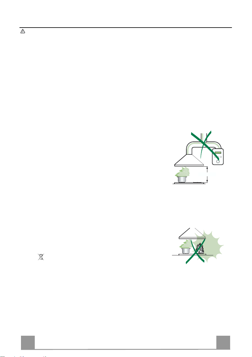
• The minimum safety distance between the cooker top and the extractor hood is 650
mm.
• Check that the mains voltage corresponds to that indicated on the rating plate fixed
to the inside of the hood.
• For Class I appliances, check that the domestic power supply guarantees adequate
earthing.
Connect the extractor to the exhaust flue through a pipe of minimum diameter 120
mm. The route of the flue must be as short as possible.
• Do not connect the extractor hood to exhaust ducts carrying combustion fumes
(boilers, fireplaces, etc.).
• If the extractor is used in conjunction with non-electrical appliances (e.g. gas burning appliances), a sufficient degree of aeration must be guaranteed in the room in
order to prevent the backflow of exhaust gas. The kitchen must have an opening
communicating directly with the open air in order to guarantee the entry of clean air.
USE
• The extractor hood has been designed exclusively for domestic use to eliminate
kitchen smells.
• Never use the hood for purposes other than for which it has ben designed.
• Never leave high naked flames under the hood when it is i n operation.
• Adjust the flame intensity to direct it onto the bottom of the pan only, making sure
that it does not engul f the sides.
• Deep fat fryers must be continuously monitored during use: overheated oil can burst
into flames.
• Do not flambè under the range hood; risk of fire
• This appliance is not intended for use by persons (including children) with reduced
physical, sensory or mental capabilities, or lack of experience and knowledge,
unless they have been given supervision or instruction concerning use of the appliance by a person responsible for thei r safety.
• Children should be su per vised to ensure that they do not pla y with the appliance.
MAINTENANCE
• Switch off or unplug the appliance from the mains supply before carrying out any
maintenance work.
• Clean and/or replace t he Filters after the specified time period.
• Clean the hood using a damp cloth and a ne utral liquid detergent.
The symbol on the product or on its packaging indicates that this product may not be treated as
household waste. Instead it shall be handed over to the applicable collection point for the recycling
of electrical and electronic equipment. By ensuring this product is disposed of correctly, you will help
prevent potential negative consequences for the environment and human health, which could otherwise be caused by inappropriate waste handling of this product. For more detailed information about
recycling of this product, please contact your local city office, your household waste disposal service
or the shop where you purchased t he product.
3
3
Page 4
EN
CHARACTERISTICS
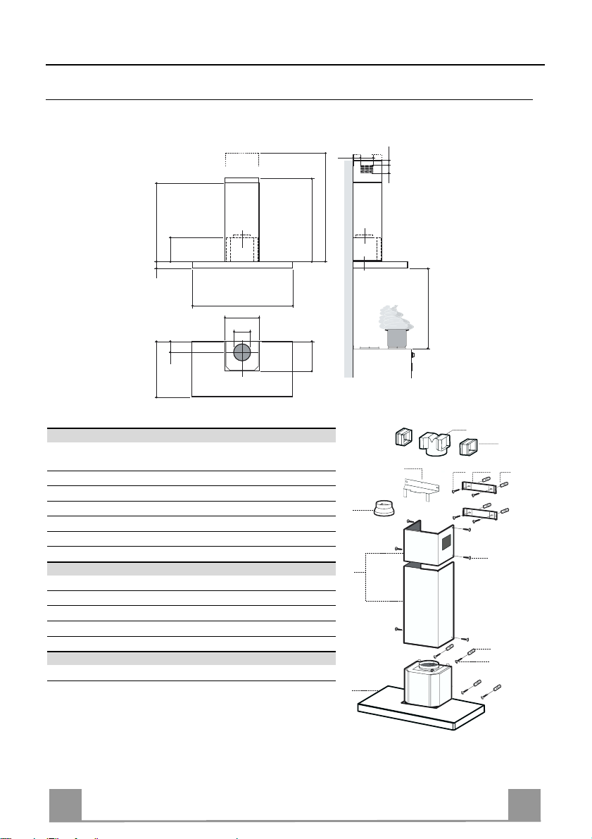
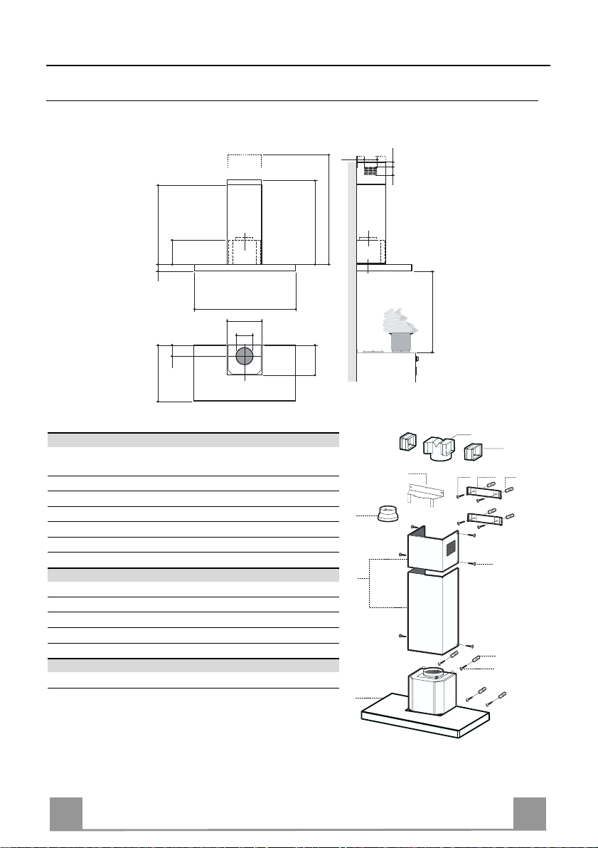
Dimensions
6341126
81
540
60
898
300
150
108 259
485
max. 1000
min. 670
260
Components
Ref. Q.ty Product Components
1 1 Hood Body, complete with: Controls, Light, Blower,
Filters
2 1 Telescopic Chimney comprising:
2.1 1 Upper Section
2.2 1 Lower Section
9 1 Reducer Flange ø 150-120 mm
14.1 2 Air Outlet Connection Extension
15 1 Air Outlet Connection
Ref. Q.ty Installation Components
7.2.1 2 Upper Chimney Section Fixing Brackets
7.3 1 Air Outlet Connection Supp ort
11 8 Wall Plugs
12a 8 Screws 4,2 x 44, 4
12c 6 Screws 2,9 x 9, 5
Q.ty Documentation
1 Instruction Manual
650 min.
15
14.1
7.3
9
2.1
2
2.2
1
12a
7.2.1 11
12c
11
12a
4
4
Page 5
EN
INSTALLATION
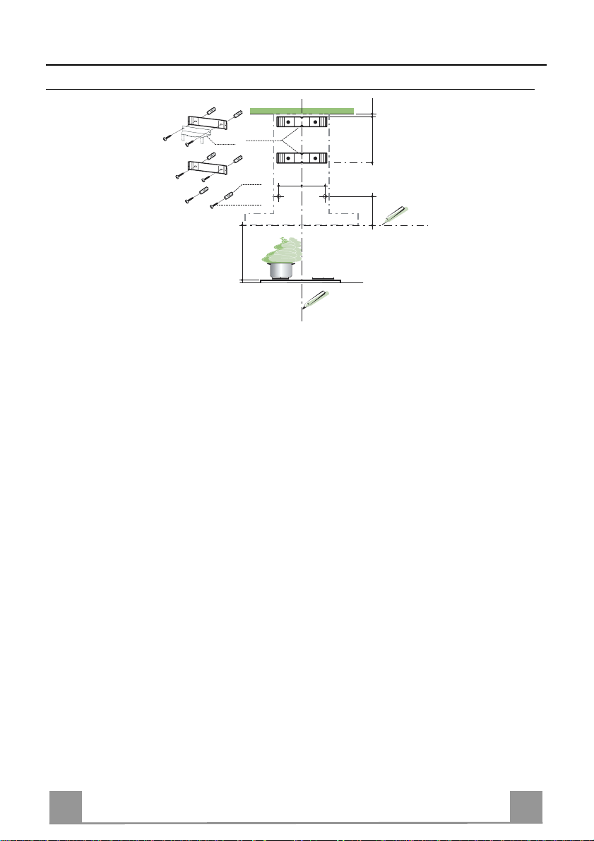
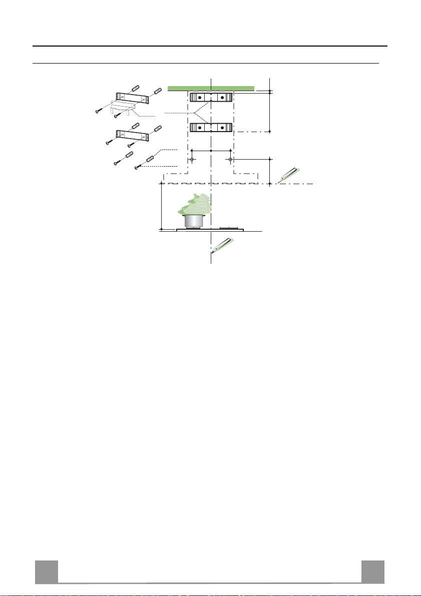
Wall drilling and bracket fixing
7.2.1
7.3
11
12a
116
116
650 min.
Wall marking:
• Draw a vertical line on the supporting wall up to the ceiling, or as high as practical, at the
centre of the area in which the hood will be installed.
• Draw a horizontal line at 650 mm above the hob.
• P l ace bracket 7.2.1 on the wall as shown about 1-2 mm from the ceiling or upper limit aligning the centre (notch) with the vertical reference line.
• Mark the wall at the centres of the holes in th e br acket.
• P l ace br acket 7.2.1 on the wall as shown at X mm below the first bracket (X = height of the
upper chimney section supplied), aligning the centre (notch) with the vertical line.
• Mark the wall at the centres of the holes in th e br acket.
• Mark a reference point as in dicated at 116 mm from the vertical reference li ne and 320 mm
above the horizontal reference l ine.
• Repeat this operation on the other side.
• Drill ø 8 mm holes at all the centre points marked.
• Insert the wall plugs 11 in the hole s.
• Fix the lower bracket 7.2.1 using the 12a screws (4,2 x 44,4) supplied.
• Fix the upper bracket 7.2.1 and the air outlet connection supp ort 7.3 to gether using the 2
screws 12a (4,2 x 44,4) supplied.
• Insert the two screws 12a (4,2 x 44,4) supplied in the hood body fixing holes, leaving a gap
of 5-6 mm between the wall and the head of the screw.
1÷2
X
320
5
5
Page 6
EN
Mounting the hoo d body
9
ø 120ø 150
ø 150
15
14.1
7.3
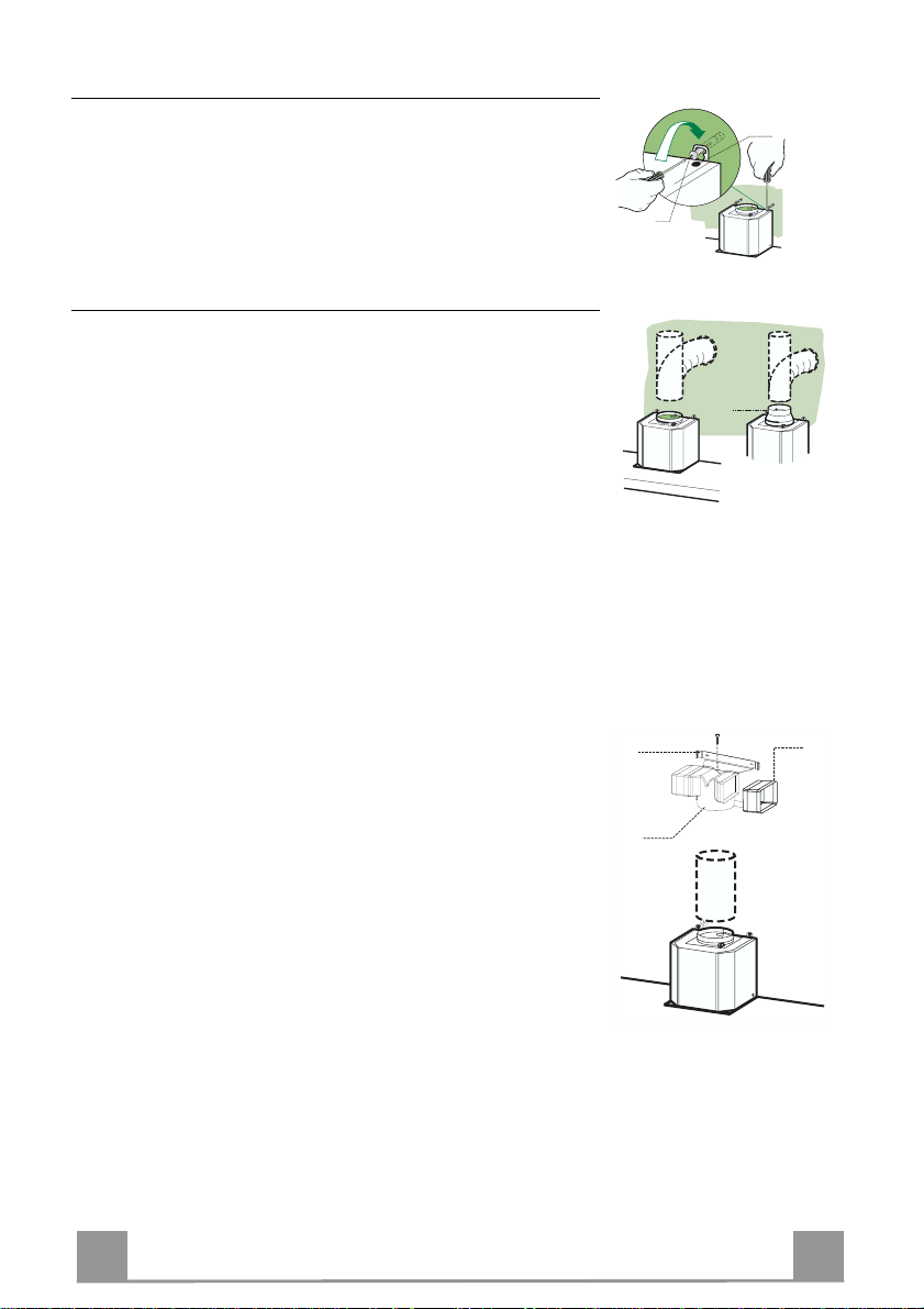
• Before attaching the hood body, tighten the two screws Vr located on
the hood body mo unt i ng points.
• Hook the hood body onto the screws 12a.
• Fully tighten support screws 12a.
• Adjust screws Vr to level the hood body.
• If necessary, it is possible to fasten the hood to the wall using more
screws with wall plugs, which can be positioned from inside the hood
canopy.
Connections
DUCTED VERSION AIR EXHAUST SYSTEM
When installing the ducted version, connect the hood to the
chimney using either a flexible or rigid pipe ø 150 or 120 mm,
the choice of which is left to the installer.
• To install a ø 120 mm air exhaust connection, insert the reducer flange 9 on the hood body outlet.
• Fix the pipe in position using sufficient pipe clamps (not supplied).
• Remove any activated charcoal filters.
Vr
12a
RECIRCULATION VERSION AIR OUTLET
• Insert the connection extension pieces lateral ly 14.1 in conn ection 15.
• Insert th e Connector 15 in to the Support bracket 7.3 and fix it
with a screw.
• Make sure that t he outlet of the extension pieces 14.1 is horizontally and vertically aligned with the chimney outlets.
• Connect the air outlet co nnection 15 to the hood body outlet
using either a flexible or rigid pipe ø 150 mm, the choice of
which is left to the installer.
• Ensure that the activated charcoal filters have been inserted.
6
6
Page 7
EN
ELECTRICAL CONNECTION
12c
2.1
2.2
2
7.2.1
12c
• Connect the hood to the mains through a two-pole switch having a contact gap of at least 3 mm.
• Re move the grease filters (see paragraph Maintenance) being
sure that the conn ector of the feeding cable is correctly inserted
in the socket placed on th e side of the fan.
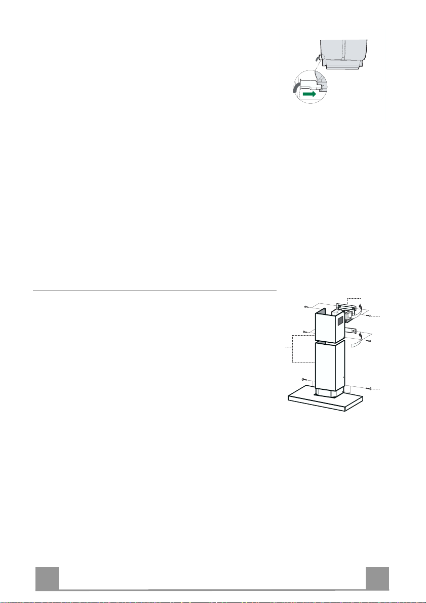
Flue assembly
Upper exhaust flue
• Slightly widen the two sides of the upper flue and hook them
behind the brackets 7.2.1, making sure that they are well
seated.
• Secure the sides to the brackets using the 4 screws 12c (2,9 x
9,5) supplied.
• Make sure that the outlet of the extension s pieces is aligned
with the chimney outlets.
Lower ex haust flue
• Slightly widen the two sides of the flue and hook them between the upper flue and t he wall, making sure that they are
well seated.
• Fix the lower part laterally to the hood body using the 2 screws
12c (2,9 x 9,5) supplied.
7
7
Page 8
EN
USE
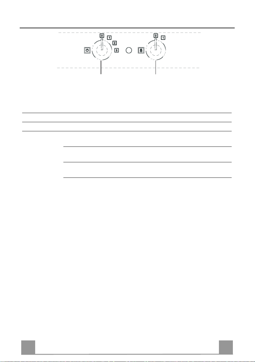
LM
By pulling out the sliding panel it is possible to automatically activate all the hood functions.
By simply closing the sliding panel all the functions are switched off.
SWITCH FUNCTIONS
L Light Switches the lighting system on and off
M Motor Switches the extractor motor on and off
1. Low speed, used for a con tinuous and silent air change i n the presence
of light cooking vapour.
2. Medium speed, suitable for most operating conditions, thanks to an optimum relation between hood performance and noise.
3. Maximum speed, suitable when the highest cooking vapour emission
has to be eliminated for longer periods.
8
8
Page 9
EN
MAINTENANCE
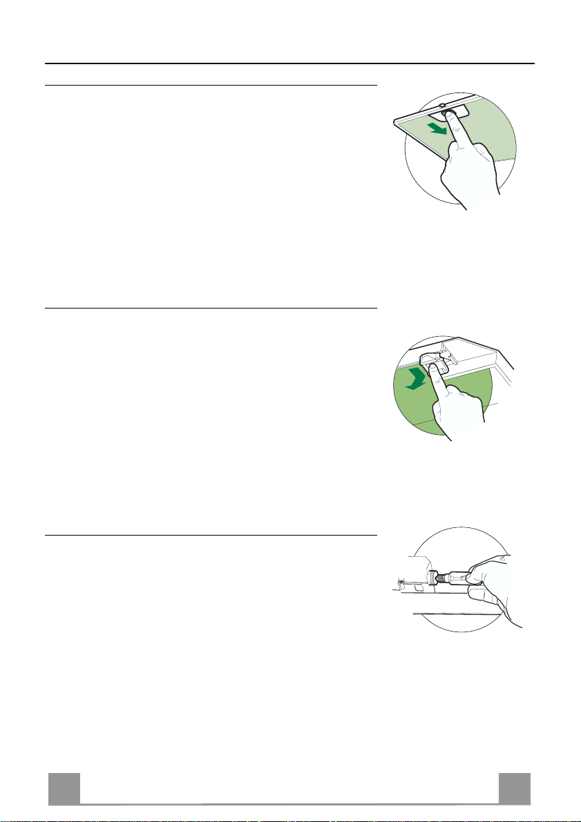
Grease filters
CLEANING META L SELF- SUPPO RTING GREASE FILTERS
• The filters must be cleaned every 2 months of operation, or
more frequently for particularly heavy usage, and can be
washed in a dishwasher.
• Remove the filters one at a time by pushing them towards the
back of the group and pulling down at the same time.
• Wash the filters, taking care not to bend them. Allow them to
dry before refitting.
• When refitting the filters, make sure that the handle is visible
on the outside.
Activated charcoal filter (Recirculation version)
REPLACING THE ACTIVATED CHARCOAL FILTE R
• The filter is not washable and cannot be regenerated, and must
be replaced approximately every 4 months of operation, or
more frequently for particularly heavy usage.
• Remove the metal grease filters
• Remove the saturated activated carbon filter by releasing the
fixing hooks
• Fit the new filter by hooking it into its seating
• Replace the metal grease filters.
Lighting
LIGHT REPLACEMENT
40 W incandescent light.
• Remove the screw fixing the Lighting support.
• Pull the Lighting support down.
• Extract the lamp and replace with another of the same type.
• Replace the lighting support in reverse order.
9
9
Page 10

IT 110
CONSIGLI E SUGGERIMENTI
650 mm min.
Questo libretto di istruzioni per l'uso è previsto per più versioni dell'apparecchio.
Possibile che siano descritti singoli particolari della dotazione, che non riguardano il
Vostro apparecchio.
INSTALLAZIONE
• Il p roduttore declina qualsiasi responsabilità per danni dovuti ad installazione non
corretta o non conforme alle regole dell’arte.
• La distanza minima di sicurezza tra il Piano di cottura e la Cappa deve essere di
650 mm.
• Verificare che la tensione di rete corrisponda a quella riportata nella targhetta posta
all’interno della Cappa.
• Per Apparecchi in Classe Ia accertarsi che l’impianto elettrico domestico g aran tisca
un corretto scarico a terra.
• Collegare la Cappa all’uscita dell’aria aspirata con tub azione di diametro pari o
superiore a 120 mm. I l percorso della tubazione deve ess er e il più breve possibi l e.
• Non collegare la Cappa a condotti di scarico dei fumi prodotti da combustione (caldaie, caminetti, ecc. ) .
• Nel caso in cui nella stanza vengano utilizzati sia la Cappa che apparecchi non
azionati da energia elettrica (ad esempio apparecchi utilizzatori di gas), si deve
provvedere ad una aerazione sufficiente dell’ambiente. Se la cucina ne fosse
sprovvista, praticare un’apertura che comunichi con l’esterno, per garantire il richiamo d’aria pulita.
USO
• La Cappa è stata progettata esclusivamente per uso domestico, per abbattere gli
odori della cucina.
• Non fare mai uso improprio della Cappa.
• Non lasciare fiamme libere a forte inten sità sotto la Cappa in funzione.
• Regolare sempre le fiamme in modo da evitare una evidente fuoriuscita laterale
delle stesse rispet to al fondo delle pentole.
• Controllare le friggitrici durante l’uso: l’olio surriscaldato potrebbe infiammarsi.
• Non preparare aliment i flambè sotto la cappa da cucina; peri colo d'incendio.
• Questo apparecchio non deve essere utilizzato da persone (bambini inclusi) con
ridotte capacità psichiche, sensoriali o mentali, oppure da persone senza esperienza e conoscenza, a meno che non siano controllati o istruiti all’uso dell’apparecchio
da persone responsabili della loro sicurezza.
• I bambini devono essere supervisionati per assicurarsi che non giochino con
l’apparecchio.
MANUTENZIONE
• Prima di procedere a qualsiasi operazione di manutenzione, disinserire la Cappa
togliendo la spina elettrica o spegnendo l’interruttore generale.
• Effettuare una sc rup o los a e tempestiva manutenzione dei F iltri s econdo gli intervalli
consigliati.
• Per la pulizia delle superfici della Cappa è sufficiente utilizzare un panno um ido e
detersivo liquido neutro.
Il simbolo sul prodotto o sulla confezione indica che il prodotto non deve essere considerato
come un normale rifiuto domestico, ma deve essere portato nel punto di raccolta appropriato per il
riciclaggio di apparecchiature elettriche ed elettroniche. Provvedendo a smaltire questo prodotto in
modo appropriato, si contribuisce a evitare potenziali conseguenze negative per l’ambiente e per la
salute, che potrebbero derivare da uno smaltimento inadeguato del prodotto. Per informazioni più
dettagliate sul riciclaggio di questo prodotto, contattare l’ufficio comunale, il servizio locale di smaltimento rifiuti o il negozio in cui è stato acquistato il prodotto.
Page 11
IT 111
CARATTERISTICHE
Ingombro
6341126
81
540
60
898
300
150
108 259
485
max. 1000
min. 670
260
Componenti
Rif. Q.tà Componenti di Prodotto
1 1 Corpo Cappa completo di: Comandi, Luce, Gruppo
Ventilatore, Filtri
2 1 Camino Telesc opico formato da:
2.1 1 Camino Superiore
2.2 1 Camino Inferiore
9 1 Flangia di Riduzione ø 150-120 mm
14.1 2 Prolunga Raccordo Uscita Aria
15 1 Raccordo Uscita Aria
Rif. Q.tà Componenti di Installazione
7.2.1 2 Staffe Fissaggio Cami no Su periore
7.3 1 Staffa Sostegno Raccordo
11 8 Tasselli
12a 8 Viti 4,2 x 44,4
12c 6 Viti 2,9 x 9,5
Q.tà Documentazione
1 Libretto Istruzioni
650 min.
15
14.1
7.3
9
2.1
2
2.2
1
12a
7.2.1 11
12c
11
12a
Page 12
IT 112
INSTALLAZIONE
Foratura Parete e Fissaggio Staffe
1÷2
7.3
7.2.1
11
12a
116
116
X
320
650 min.
Tracciare sulla Parete:
• una linea Verticale fino al soffitto o al limite superiore, al centro della zona prevista per il
montaggio della Cappa;
• una linea Orizzontale a: 650 mm min. sopra il Piano di Cottura.
• Appoggiare come indicato la Staffa 7.2.1 a 1-2 mm dal soffitto o dal limite superiore, allineando il suo centro (intagli) sulla linea Verticale di riferimento.
• Segnare i centri dei Fori della Staffa.
• Appoggiare come indicato la Staffa 7.2.1 a X mm sotto la prima staffa (X = altezza Camino
Superiore in dotazione), allineando il suo centro (intagli) sulla linea Verticale di riferimento.
• Segnare i centri dei Fori della Staffa.
• Segnare come indicato, un punto di riferimento a 116 mm dalla linea Verticale di riferimento, e 320 mm sopra la linea Orizzontale di riferimento.
• Ripetere questa operazione dalla parte opposta.
• Forare ø 8 mm i punti segnati.
• Inserire i tasselli 11 nei fori.
• Fissare la Staffa inferiore 7.2.1 utilizz a ndo le Vi ti 12a (4,2 x 44,4 ) in dotazione.
• Fissare insieme la Staffa superiore 7.2.1 e la Staffa sostegno raccordo 7.3 utilizzando le 2
viti 12a (4,2 x 44,4) in dotazione.
• Avvitare 2 Viti 12a (4,2 x 44,4) in dotazione nei fori per il fissaggio del corpo Cappa, lasciando uno spazio di 5-6 mm fra la parete e la testa della vite.
Page 13

IT 113
Montaggio Corpo Cappa
9
ø 120ø 150
ø 150
15
14.1
7.3
• Prima di agganciare il Corpo Cappa, serrare le 2 Viti Vr situate sui
punti di aggancio de l Corpo Cappa.
• Agganciare il Corpo Cappa alle Viti 12a.
• Serrare definitivamente le Viti 12a di supporto.
• Agire sulle Viti Vr per livellare il Co rpo Cappa.
• Nel caso si ritenga opportuno è possibile assicurare la cappa al muro
per mezzo di altre viti con tassello, posizionabili dal
cappa
.
l’interno del corpo
Connessioni
USCITA ARIA VERSIONE ASPIRANTE
Per installazione in Versione Aspirante collegare la Cappa alla
tubazione di uscita per mezzo di un tubo rigido o flessibile di
ø150 o 120 mm, la cui scelta è lasciata all'installatore.
• Per collegamento con tubo ø120 mm, inserire la Flangia di riduzione 9 sull’Uscita del Corpo Cappa.
• Fissare il tubo con adeguate fascette stringitubo. Il materiale
occorrente non è in dotazione.
• Togliere eventuali Filtri Antiodore al Carbone attivo.
Vr
12a
USCITA ARIA VERSIONE FILTRANTE
• Inserire lateralmente le Prolunghe Raccordo 14.1 sul Raccordo
15.
• Inserire il Racco rdo 15 nella Staffa di Sostegno 7.3 fissandolo
con una Vite.
• Assicurarsi che l’uscita delle Prolunghe Raccordo 14.1 risulti
in corrispondenza delle bocchette del Camino sia in orizzontale
che in verticale.
• Co llegare il Raccordo 15 all’Uscita del Corpo Cappa per mezzo di un tubo rigido o flessibile di ø150 mm, la cui scelta è lasciata all'installatore.
• Assicurarsi della presenza del Filtro Antiodore al Carbone attivo.
Page 14

IT 114
CONNESSIONE ELETTRICA
12c
2.1
2.2
2
7.2.1
12c
• Collegare la Cappa all’Alimentazione di Rete interponendo un
Interruttore bipolare con apertura dei contatti di almeno 3 mm.
• Rimuovere i Filtri antigrasso (vedi par. “Manutenzione”) e assicurarsi che il connettore del Cavo di alimentazione sia correttamente inserito nella presa dell’Aspiratore
Montaggio Camino
Camino superiore
• Allargare leggermente le due falde laterali, agganciarle dietro
le Staffe 7.2.1 e richiuderle fino a battuta.
• Fissare lateralmente alle Staffe con 4 Viti 12c (2,9 x 9,5) in
dotazione.
• Assicurarsi che l’uscita delle Prolunghe Racco rdo risulti in corrispondenza delle bocc hette de l C am i no.
Camino inferiore
• Allargare leggermente le due falde laterali del Camino, agganciarle tra il Camino superiore e la parete e richiuderle fino a
battuta.
• Fissare lateralmente la parte inferiore al Corpo Cappa, con 2
Viti 12c (2,9 x 9,5) in dotazione.
Page 15

IT 115
USO
LM
Le varie funzioni vengono attivate automaticamente con l’estrazione del carrello. Per spegnere
le funzioni impostate sarà sufficiente richiudere il carrello.
TASTO FUNZIONE
L Luci Accende e spegne l’Impianto di Illuminazione.
M Motore Accende e spegne il motore Aspirazione.
1. Velocità minima, adatta ad un ricambio d’aria continuo particolarmente
silenzioso,in presenza di pochi vapori di cottura.
2. V elocità media, adatta alla maggior parte delle condizioni d’uso, dato
l’ottimo rapporto tra portata d’aria trattata e livello sonoro.
3. Velocità massima, adatta a fronteggiare grandi emissioni di vapore di
cottura,anche per tempi prolungati.
Page 16

IT 116
MANUTENZIONE
Filtri antigrasso
PULIZIA FILTRI ANTIGRASSO METALLICI AUTOPORTANTI
• Sono lavabili anche in lavastoviglie, e necessitano di essere
lavati ogni 2 mesi circa di utilizzo o più frequentemente, per un
uso particolarmente intenso.
• Togliere i Filtri uno alla volta, spingendoli verso la parte posteriore del gruppo e tir ando contemporaneamente verso il basso.
• Lavare i Filtri evitando di piegarli, e lasciarli asciugare prima
di rimontarli.
• Rimontarli facendo attenzione a mantenere la maniglia verso la
parte visibile esterna.
Filtro antiodore (Versione Filtrante)
SOSTITUZIONE FILTRO ANTIODORE AL CARBONE ATTIVO
• Non è lavabile e non è rigenerabile, va sostituito almeno ogni 4
mesi o più frequentemente, per un uso particolarmente intenso.
• Togliere i Filtri antigrasso metallici.
• Rimuovere il Filtro antiodore al Carbone attivo saturo, agendo
sugli appositi agganci.
• Montare il nuovo Filtro agganciandolo nella sua sede.
• Rimontare i Filtri antigrasso metallici.
Illuminazione
SOSTITUZIONE LAMPADE
Lampade a incandescenz a da 40 W.
• Togliere la vite che fissa la plafoniera.
• Tirare la plafoniera verso il basso.
• Svitare la lampada e sostituirla con una nuova di uguali caratteristiche.
• Rimontare la plafoniera in sequenza inversa.
Page 17

FR 117
CONSEILS ET SUGGESTIONS
650 mm min.
La présente notice d'emploi vaut pour plusieurs versions de l'appareil. Elle peut contenir des
descriptions d'accessoires ne figurant pas dans votre appareil.
INSTALLATION
• Le fabricant décline toute responsabilité en cas de dommage dû à une installation non correcte ou non conforme aux règles de l’art.
• La dis ta nc e mi nim al e d e séc uri té entr e l e pl an de c uis so n et l a h ott e doi t êtr e de 650 m m au
moins.
• Vérifier que la tension du secteur correspond à la valeur qui figure sur la plaquette apposée à
l’intérieur de la hotte.
• Pour les Appareils appartenant à la Ière Classe, veiller à ce que la mise à la terre de
l’installation électrique do mestique ait été effe ctuée confo rmément aux norme s en vigueur.
• Connecter la hotte à la sortie d’a i r aspiré à l’aide d’u n e tuyauterie d’un diamètre égal ou supérieur à 120 mm. Le parcours de la tuyauterie doit être le plus court possible.
• Eviter de connecter la hotte à des conduites d’évacuation de fumées issues d’une combustion tel que (Chaudière, cheminée, etc…).
• Si vous utilisez des appareils qui ne fonctionnent pas à l’électricité dans la pièce ou est installée la hotte (par exemple: des appareils fonctionnant au gaz), vous devez prévoir une aération suffisante du milieu. Si la cuisine en est dépourvue, pratiquez une ouverture qui communique avec l’extérieur pour garantir l’infiltration de l’air p ur.
UTILISATION
• La hotte a été conçu e exclusivemen t pour l’usage dom estique, dans le but d’éliminer les
odeurs de la cuisine.
• Ne jamais utiliser abusivement la hotte.
• Ne pas laisser les flammes libres à forte intensité quand la hotte est en service.
• Toujours régl er les flamm es de manièr e à éviter tout e sortie lat érale de ces dernières par
rapport au fond des marmites.
• Contrôler les friteuses lors de l’utilisat ion car l’huile su rchauffée pou rrait s’enf lammer.
• Ne pas préparer d’aliments flambés sous la hotte de cuisine : risque d’incend ie
• Cet appareil ne doit pas être utilisé par des personnes (y compris les enfants) ayant des
capacités psychi ques, s ensoriel les ou m entales réduite s, ni par des pers onnes n’ ayant pas
l’expérience et la connaissance de ce type d’appareils, à moins d'être sous le contrôle et la
formation de per sonnes responsables de leur sécurité.
• Les enfants doivent être surveillés pour s'assurer qu' ils ne jouent pa s avec l'appare il.
ENTRETIEN
• Avant de pr océder à toute op ération d’ entr etien, reti rer la h otte en reti rant l a fiche ou en actionnant l’interrupteu r général.
• Effectuer un entretien scrupuleux et en temps dû des Filtres, à la cadence conseillée.
• Pour le nettoyage des surfaces de la hotte, il suffit d’utiliser un chiffon humide et détersif
liquide neutre.
Le symbole sur le produit ou son emballage indique que ce produit ne peut être traité comme déchet
ménager. Il doit plutôt être remis au point de ramassage concerné, se chargeant du recyclage du matériel
électrique et électronique. En vous assurant que ce produit est éliminé correctement, vous favorisez la
prévention des conséquences négatives pour l’environnement et la santé humaine qui, sinon, seraient le
résultat d’un traitement inapproprié des déchets de ce produit. Pour obtenir plus de détails sur le recyclage
de ce produit, veuillez prendre contact avec le bureau municipal de votre région, votre service d’élimination
des déchets ménagers ou le magasin où vous avez achet é l e produi t .
Page 18

FR 118
CARACTERISTIQUES
Encombrement
6341126
81
540
60
898
300
150
108 259
485
max. 1000
min. 670
260
Composants
Réf. Q.té Composants de Produit
1 1 Corps Hotte équ ipé de:Command es, Lumière, Groupe
Ventilateur,Filtres
2 1 Cheminée Télescopique formée de :
2.1 1 Cheminée Supérieure
2.2 1 Cheminée Inférieure
9 1 Flasque de Réduction ø 150-120 mm
14.1 2 Rallonge Raccord Sortie Air
15 1 Raccord Sortie Air
Réf. Q.té Composants pour l ’installation
7.2.1 2 Brides Fixation Cheminée Supérie ure
7.3 1 Bride Support Raccord
11 8 Chevilles
12a 8 Vis 4,2 x 44,4
12c 6 Vis 2,9 x 9,5
Q.té Documentation
1 Manuel d’instructions
650 min.
15
14.1
7.3
9
2.1
2
2.2
1
12a
7.2.1 11
12c
11
12a
Page 19

FR 119
INSTALLATION
Perçage Paroi et Fixation Brides
1÷2
7.2.1
7.3
X
116
116
11
12a
320
650 min.
Tracer sur la paroi:
• une ligne verticale allant jusqu’au plafond ou à la limite supérieure, au centre de la zone
prévue pour le montage de la hotte;
• une ligne horizontale à 650 mm min. au-dessus du plan de cuisson.
• Poser comme indiqué une bride 7.2.1 sur la paroi à 1-2 mm du plafond ou de la limite supérieure, en alignant son centre (découpes) sur la ligne verticale de repère.
• Marquer les centres des trous rainurés de la bride.
• Poser comme indiqué la bride 7.2.1 à X mm sous la première bride (X = hauteur cheminée
supérieure fournie), en align ant son centre (découpes) sur la ligne verticale de repère.
• Marquer les centres des trous rainurés de la bride.
• Marquer comme indiqué, un point de référence à 116 mm de la ligne verticale de repère, et
320 mm au-dessus de la ligne horizontale de repère.
• Répéter cette opération sur le côté opposé.
• Percer de ø 8 mm tous les points marqués.
• Insérer les chevilles 11 dans les trous.
• Fixer la bride inférieure 7.2.1 en utilisant les vis 12a (4,2 x 44,4) fournies.
• Fixer ensemble la bride supérieure 7.2.1 et le support 7.3 en utilisant les vis 12a (4,2 x 44,4)
fournies.
• Visser les 2 vis 12a (4,2 x 44,4) fournies dans les trous de fixation du corps hotte, en laissant
un le espace de 5-6 mm entre le mur et la tête de la vis
Page 20

FR 220
Montage Corps Hotte
9
ø 120ø 150
ø 150
15
14.1
7.3
• Avant d’accrocher le corps hotte, serrer les deux vis Vr situées sur les
points d’accrochage du corps hotte.
• Accrocher le corps hotte aux vis 12a prévues à cet effet.
• Serrer définitivement les vis 12a de support.
• Agir sur les vis Vr pour niveler le corps hotte.
• Si cela est jugé nécessaire, il est possible de fixer la hotte au mur au
moyen de chevilles et vis supplémentaires qu’il faudra placer de
l’intérieur du co r ps de la hotte.
Branchements
SORTIE AIR VERSION ASPIRANTE
En cas d’installation en version aspirante, brancher la hotte à la
tuyauterie de sortie via un tube rigide ou flexible de ø 150 ou 120
mm, au choix de l’installateur.
• En cas de branchement avec un tu be de ø120 mm, insérer le
flasque de réduction 9 sur la sortie du corps de la hotte.
• Fixer le tube par des colliers appropriés. Le matériau nécessaire n’est pas fourni.
• Retirer les éventuels filtres anti-odeur au charbon actif.
SORTIE AIR VERSION FILTRANTE
Vr
12a
• Insérer latéralement les rallonges raccord 14.1 sur le raccord
15.
• Placer le raccord 15 dans l’étrier de soutien 7.3 en le fixant
avec une vis.
• S’assurer que la sortie des rallonges racco rd 14.1 se trouve au
niveau des bouches de la cheminée aussi bien en horizontal
qu’en vertical.
• Bran cher le raccord 15 à la sortie du corps de la hotte avec un
tube rigide ou flexible de ø 150 mm, selon le choix de
l’installateur.
• S’assurer de la présence des filtres anti-odeur au charbon actif.
Page 21

FR 221
BRANCHEMENT ELECTRIQUE
12c
2.1
2.2
2
7.2.1
12c
• Brancher la hotte sur le secteur en interpo sant un interrupteur
bipolaire avec ouvertu re des contacts d’au moins 3 mm.
• Enlever les filtres à graisse (voir § "Entretien") et s'assurer que
le connecteur du câbl e d'al imentati on so it bien bran ché dan s la
prise du diffuseur.
Montage Cheminée
Cheminée supérieure
• Elargir légèrement les deux bords latériaux, et les accrocher
derrières les brides 7.2.1 ; refermer
jusqu’à la butée.
• Fixer latéralement aux brides à l’aide des 4 vis
12c fournies.
• S’assurer que la sortie des rallonges raccord se trouve au niveau des bouches de la cheminée.
Cheminée inférieure
• Elargir légèrement les deux bords latériaux de la Cheminée et
les accrocher entre la Cheminée sup éri eure et la paroi; refermer
jusqu’à la butée.
• Fixer latéralement la partie inférieure au corps
hotte, à l’aide des deux 2 vis 12c fournies.
Page 22

FR 222
UTILISATION
LM
Les différentes fonctions de la hotte sont activées automatiquement avec l’ouverture du tiroir.
Pour arrêter les fonctions sélectionnées il suffit de fermer le tiroir.
TOUCHE FUNCTIONS
L Lumières Allume et éteint l’éclairage.
M Moteur Allume et éteint le moteur aspiration
1. Vitesse minimale, pour un rechange d’air permanent particulièrement
silencieux en cas de faibles vapeurs de cuisson.
2. Vitesse moyenne pour la plupart des conditions d’utilisation, étant donné le rapport optimal entre débit d’air traité et niveau sonore.
3. Vitesse maximum, pour faire face aux émissions maximum de vapeur
de cuisson, même pendant des temps prolongés .
Page 23

FR 223
ENTRETIEN
Filtres anti-graisse
NETTOYAGE FILTRE S ANTI -GRAISS E METALLI QUES AUTOPO RTEUR S
• Lavables au lave-vaisselle, ils doivent être lavés environ tous
les 2 mois d’emploi ou plus fréquemment en cas d’emploi particulièrement intense.
• Retirer les filtres l’un aprés l’autre, en les poussant vers la partie arrière du groupe et en tirant simultanément vers le bas.
• Laver les filtres en évitant de les plier et les laisser sécher avant
de les remonter.
• Remonter les filtres en veillant à ce que la poignée reste vers la
partie visible externe
Filtre anti-odeur (Version filtrante)
REMPLACEMENT FILTRE AU CHARBON ACTIF
• Ni lavable, ni régénérable, le remplacer au moins tous les 4
mois d’emploi ou plus fréquemment en cas d’emploi particulièrement intense.
• Retirer les filtres anti-graisse métalliques.
• Retirer le filtre anti-odeur au charbon actif colmaté, en agissant
sur les crochets prévus à cet effet.
• Monter le nouveau filtre anti-odeur au charbon actif.
• Remonter les filtres anti-graisse métalliques.
Eclairage
REMPLACEMENT LAMPES
Lampe à incandescence de 40 W.
• Retirer la vis qui fixe le Support éclairage.
• Tirer le Support vers le bas.
• Extraire la Lampe du Support.
• Remplacer par une nouvelle lampe possédant les mêmes caractéristiques.
• Remonter le Support éclairage.
Page 24

DE 224
EMPFEHLUNGEN UND HINWEISE
650 mm min.
Diese Gebrauchsanleitun g gilt für mehrere Gerät e-Ausführungen. Es i st möglich, dass
einzelne Ausstattungsmerkmale beschrieben sind, die nicht auf Ihr Gerät zutreffen.
MONTAGE
• Das Gerät darf nur vom Fachpersonal angeschlossen werden.
• Der Herstell er haft et nicht für Schäden , die auf ei ne fehler haft e und uns achg emäße M ontage zurückzuführen sind.
• Der minimale Si cherheits abstand zw ischen K ochmulde u nd Haube mus s 650 mm be tragen.
• Prüfen, ob die Netzspannun g mit dem Wer t auf dem im Haubeninner en angebrachten Schild übereinstimmt.
• Bei Ger ät e n der Klasse I ist sicherzust el l e n, dass die elektrische Anl a ge des Wohnhauses
über eine vorschriftsmäßige Erdung verfügt.
• Das Anschlussrohr der Haube zur Luftaustrittsöffnung sollte möglicherweise einen
Durchmesser von 150 mm aufweisen. Der Rohrverlauf muss so kurz wie möglich sein.
• Die Haube darf an keine Entlüftungsschächte angeschlossen werden, in die Verbrennungsgase (Heizkessel, Kamine usw.) geleitet werden.
• Werden im Raum außer der Dunstabzugshaube andere, nicht elektrisch betriebene (z.B.
gasbetriebe ne) Geräte verwendet, m uss für eine ausreichende B el ü ftung gesorgt werden.
Sollte die K üche dies bezügli ch ni cht entspr echen , ist an ei ner Aus sen wand ei ne Öf fnun g
anzubringen , di e Fri s c hluftzufuhr gewährleis tet .
BEDIENUNG
• Die Dunstabzugs haube is t ausschl ießlich zum Einsatz i m private n Haushalt und zur B eseitigung von Küc hengerüchen vorgesehen.
• Bei unsachgemäßer Benutzung wird keine Haftung übernommen.
Achtung! Große Flammen bei eingeschalteter Haube niemals unbedeckt lassen.
• Die Intensivität der Flamme ist so zu regulieren, dass sie den Topfboden nicht überragt.
Achtung! Frittiergeräte müssen wä hrend des Gebrauchs stets beaufsichtigt werden: Überhitztes Öl kann sich entzünden.
• Keine flambierten Speisen unter der Abzugshaube zubereiten: Brandgefahr.
• Dieses Gerät darf nicht von Personen, auch Kindern, mit verminderten psychischen,
sensorische n und geisti gern Fähi gkeiten, o der von Personen ohne Erfahru ng und Ken ntnisse benutzt werden, sofern sie nicht von für ihre Sicherheit verantwortlichen Personen
beaufsichtigt und beim Gebrauch des Geräts angeleitet werden.
• Kinder d ürf en s ic h ni cht unbe a ufsic hti gt i n der Nähe des Ger äts auf hal ten un d au f k ein en
Fall mit dem Gerät spielen.
WARTUNG
• B evor Wartungsarbei ten durchgeführt w erden, muss die Str omzufuhr zur Hau be unterbrochen werde n, ind em der Stecker gezogen oder der Hau pts c h al ter abgeschaltet wird.
• B ei der Filterwartun g müssen die vom H ersteller empfo hlenen Zeiträume z um Austauschen der Filter genauestens eingehalten werden.
• Zur Reini gung d er H aubenfl äch en Wi r empf ehlen ein feuc htes T uch u nd ei n mil des Fl üssigreinigungsmittel.
• Bitte keine Reinigungsmittel mit Scheuermittel verwenden. Die Oberfläche wird damit
verkratzt.
Das Symbol auf dem Produkt oder seiner Verpackung weist darauf hin, dass dieses Produkt nicht als
normaler Haushaltsabfall zu behandeln ist, sondern an einem Sammelpunkt für das Recycling von elektrischen und elektronischen Geräten abgegeben werden muss. Durch Ihren Beitrag zum korrekten Entsorgen
dieses Produkts schützen Sie die Umwelt und die Gesundheit Ihrer Mitmenschen. Umwelt und Gesundheit
werden durch falsches Entsorgen gefährdet. Weitere Informationen über das Recycling dieses Produkts
erhalten Sie von Ihrem Rathaus, Ihrer Müllabfuhr oder dem Geschäft, in dem Sie das Produkt gekauft haben.
Page 25

DE 225
CHARAKTERISTIKEN
Platzbedarf
6341126
81
540
60
898
300
150
108 259
485
Komponenten
Pos. St. Produktkomponenten
1 1 Haubenkörper mit Schaltern, Beleuchtung, Gebläse-
gruppe, Filter
2 1 Teleskopkamin bestehend aus:
2.1 1 oberer Kaminteil
2.2 1 unterer Kaminteil
9 1 Reduzierflansch ø 150-120 mm
14.1 2 Verlängerung Luftaustritt-Anschlussstück
15 1 Luftaustritt-Anschlussstück
Pos. St. Montagekomponenten
7.2.1 2 Befestigungsbügel oberer Kamintei l
7.3 1 Bügel für Anschlusshalter
11 8 Dübel
12a 8 Schrauben 4,2 x 44,4
12c 6 Schrauben 2,9 x 9,5
St. Dokumentation
1 Bedienungsanleitung
min. 670
260
max. 1000
650 min.
15
14.1
7.3
9
2.1
2
2.2
1
12a
7.2.1 11
12c
11
12a
Page 26

DE 226
MONTAGE
Bohren der Befestigungslöcher und Fixieren der Befestigungsbügel
7.2.1
7.3
116
116
11
12a
650 min.
Achtung: Bitte beachten Sie bei der Montage das Gewicht der kompletten Haube. Die Tragfä-
higkeit der Decke oder alternativ der Trägerplatte für diese Zugbelastung muss vor der Montage geprüft und gegebenenfalls durch die Anbringung von geeigneten Befestigungs- oder
Stabilisierungselementen hergestellt werden. Kann eine hinreichende Tragfähigkeit nicht sichergestellt werden, ist von einer Montage abzusehen.
Nachstehende Linien an die Wand zeichnen:
• Eine vertikale Linie bis zur Decke oder oberen Begrenzung, und zwar in der Mitte des Bereiches,in dem die Haube montiert werden soll;
• Eine horizontale Linie: mit einem minimalen Abstand von 650 mm zur Kochfläche.
• Einen Bügel 7.2.1 zirka 1-2 mm unter der Decke oder oberen Begrenzung an die Wand l e-
gen und seinen Mittelpunkt (Einschnitte) auf die vertikale Bezugslinie ausrichten.
• Die Mitte der beiden Bügellöcher an der Wand markieren.
• Den zweiten Bügel 7.2.1 an die Wand legen, wobei ein Abstand X mm vom oberen Bügel
einzuhalten ist (X = Höhe des jeweiligen oberen Kaminteils); den Mittelpunkt (Einschnitte)
auf die vertikale Bezugslinie ausrichten.
• Die Mitte der Bügellöcher an der Wand markieren.
• Wie beschrieben einen Bezugspunkt 116 mm von der vertikalen Bezugslinie und 320 mm
oberhalb der horizontalen Bezugslinie kennzeichnen.
• Gleichermaßen an der gegenüberliegenden Seite vorgehen.
• Mit einem Bohrer ø 8 mm die markierten Punkte bohren.
• Die Dübel 11 in die Bohrungen einfügen.
• Den unteren Bügel mit den mitgelieferten Schrauben 12a (4,2 x 44,4) fi xieren.
• Den Bügel für Anschlusshalter mit den 2 mitgelieferten Schrauben 12a (4,2 x 44,4) auf den
oberen Bügel 7.2.1 befestigen.
• 2 der mitgelieferten Schrauben 12a(4,2 x 44,4)bei den Befestigungslöchern des Haubenkör-
pers einschrauben, wobei zwischen Wand und Schraubenkopf ein Freiraum von 5-6 mm zu
belassen ist.
1÷2
X
320
Page 27

DE 227
Montage des Haubenkörpers
9
ø 120ø 150
ø 150
15
14.1
7.3
• Bevor der Haubenkörper eingehakt wird, die 2 Schrauben Vr bei den
Haubenkörper-Anhakpunkten festziehen.
• Den Haubenkörper bei de n S c hr aube n 12a einhänge n.
• Die Halteschrauben 12a definitiv festziehen.
• Den Haubenkörper mit Hilfe der Schrauben Vr ausrichten.
• Die Haube kann bei Bedarf mit Hilfe weiterer Schrauben und Dübel
von innen an der Wand gesichert werden.
Anschluss der Abluftversion
Bei Abluftbetrieb kann die Haube vom Installateur wahlweise
mittels Rohr oder Schlauch (ø 150 oder 120 mm) an die Außenrohrleitung angeschlossen werden.
• Bei Verwendung eines Anschlussrohres ø 120 den Reduzierflansch 9 am Haubenaustritt anbringen.
• Das Rohr mit geeigneten Rohrschellen fixieren. Das hierzu
erforderliche Material wird nicht mitgeliefert.
• Eventuell vorhandene Aktivkohlefilter entnehmen.
Achtung! Alle Querschnittänderungen oder Richtu ngsän-
derungen de s Abluf tkan als red uzieren die Lei stung der Haube.
Vr
12a
Anschluss der Umluftversion
• Die Verl ängeru ngen 14.1 beim Anschluss 15 seitlich einfügen.
• Den Anschluss 15 am Haltebügel 7.3 einsetzen un d mit einer
Schraube fixieren.
• Überpr üfen, ob die V erlängerungen 14.1 mit den entsprechenden Kaminstutzen sowohl horizontal wie auch vertikal übereinstimmen.
• Vom Installateur wahlweise mittels Rohr oder Schlauch (ø 150
mm), den Anschluss 15 am Haubenaustritt anbringen.
• Kontrollieren, ob der Aktivkohle-Geruchsfilter montiert ist.
Page 28

DE 228
Elektroanschluss
12c
2.1
2.2
2
7.2.1
12c
Vor der Installation die Netzspannung durch herausdrehen der
Sicherung oder ausschalten des Hauptschalters s tromlos machen.
• Bei Anschluss der Haube an das Stromnetz muss ein
zweipoliger Schalter mit einem Öffnungsweg von
mindestens 3 mm zwischengeschaltet werden.
• Entfernen Sie die Fettfilter (s. Abschnitt „Wartung“) und
versichern Sie sich, daß die Kabel verbindung in die Steckdose des Gebläses einwandfrei eingesteckt wird.
Achtung: Das Gerät nur an die Netzspannung die im Typen-
schild angegeben ist anschließen.
Kaminmontage
Oberer Kaminteil
• Die beiden seitlichen Schenkel leicht auseinanderbiegen, hinter
den Bügeln 7.2.1 einhängen und bis zum Anschlag wieder
schließen.
• Bei den Bügeln 7.2.1 mit Hilfe der 4 mitgelieferten Schrauben
12c fixieren.
• Überprüfen, ob die Verlängerungen mit den entsprechenden
Kaminstutzen überein stimmen.
Unterer Kaminteil
• Die beiden seitlichen Schenkel des Kaminteils leicht auseinander biegen, zwischen dem oberen Kaminteil und der Wand
einhängen und bis zum Anschlag wieder schließen.
• Den unteren Teil seitlich am Haubenkörper mit 2 der mitgelieferten Schrauben 12c fixieren.
Page 29

DE 229
BEDIENUNG
LM
Die verschiedenen Funktionen werden automatisch beim Ausziehen des Wrasenleitschirms
eingeschaltet. Um die F unktionen wieder auszuschalten, den Wrasenleit schirm einschieben.
SCHALTER FUNKTION
L Beleuchtung Schaltet die Beleuchtung ein und aus
M Motor Schaltet den Gebläsemotor ein und aus
1. kleinste Gebläsestufe, diese Stufe ist für den geräuscharmen Dauerbetrieb der Haube bei geringer Wrasenentwicklung auf dem Kochfeld geeignet.
2. mittlere Gebläsestufe, eignet sich durch das gute Verhältnis zwischen
Geräuschentwicklung und Luftförderleistung für die meisten Kochsituationen.
3. höchste Gebläsestufe, eignet sich für starke Wrasenentwicklung auf
dem Kochfeld, auch über längere Zeit hin.
Page 30

DE 330
WARTUNG
Fettfilter
SELBSTTRAGENDER METALLFETTFILTER REINIGUNG
• Sie müssen nach 2-monatigem Betrieb bzw. bei starkem Einsatz auch häufiger gereinigt werden, was im Geschirrspüler
möglich ist.
• Die Filter nacheinander aushaken, indem sie auf die Rückseite
der Gruppe geschoben und gleichzeitig nach unten gezogen
werden.
• Die Filter reinigen (darauf achten, sie nicht zu verbiegen) und
vor der Remontage trocknen lassen.
• Bei der Remontage ist darauf zu achten, dass sich der Griff auf
der sichtbaren Außenseite befindet.
Geruchsfilter (Umluftversion)
AUSTAUSCHEN DER AKTIVKOHLE FILTER
• Dieser Filter kann weder gewaschen noch wiederverwendet
werden und ist alle 4 Betriebsmonate bzw. bei starkem Einsatz
auch häufiger auszutauschen.
• Die Metallfettfilter entfernen.
• Den gesättigten Aktivkohle-Geruchsfilter aushaken.
• Den neuen Filter in seinem Sitz einhaken.
• Die Metallfettfilter wieder montieren.
• Die Kohlefilter können mit dem Hausmüll entsorgt werden.
Beleuchtung
AUSWECHSELN DER LAMPEN
Glühlampen 40 W
• Die Schraube der Lampenhalterung lösen.
• Die Lampenhalterung nach unten ziehen.
• Die Lampen herausziehen und durch ei ne neue ersetzen.
• Die Halterung wieder montieren.
Page 31

TR 331
TAVSIYELER VE ÖNERILER
650 mm min.
Bu kullanma talimatι birden fazl a ci haz modeli içi n geçer li dir .
Cihazιnιza uy may an baz ι donanιm özellikleri tarif edilmiş olabilir.
MONTAJ
• Yalnιş veya eksik mo nta jda n doğan he rha ngi b ir zara rιn sorumluluğu üreticiye ait
değildir.
• Davlumbaz ile pişirici cihazιn ocak kιsmι arasιndaki minimum güvenlik mesafesi
650 mm.dir.
• Besleme voltajιnιn, davlumbaz içerisine yerleştirilen bilgi etiketinde belirtilenle
aynι olup olmadιğιnι kontrol edin.
• Sιnιf I elektrikli aletleri için, güç kaynağιnιn yeterli topraklamayι sağlayιp
sağlamadιğιnι kontrol edin. Minimum 120 mm çapιnda bir boru yoluyla
davlumbazι çιkιş bacasιna bağlayιn. Baca bağl ant ιsι mümkün oldu- ğunca kιsa
olmalιdιr.
• Davlumbaz borusunu yanιcι duman taşιyan baca deliğine (buhar kazanι, şömine,
vb.) bağlamayιn.
• Davlumbazιn elektrikle çalιşmayan aletlerle (örneğin; gazlι cihazlar) bağιntιlι olarak kullanιlmamasι halinde çιkιş gazιnιn geri tepmesini önlemek amacιyla odada
yeterli bir havalandιrma sağlanmalιdιr. Temiz hava girişini temin etmek için mutfakta doğrudan dιşar ιya açιlan bir açιklιk bulunmalιdιr.
KULLANIM
• Davlumbaz mutfaktaki kokularιn emilmesi amacιyla evlerde kullanιm için
tasarlanmιştιr .Ti cari v e endüst r iyel amaçl ar iç in kul lanmayιnιz.
• Davlumbazι tasarlandιğι amaçlarιn dιşιnda kesinlikle kullanmay ιnιz.
• Davlumbaz çalιşιrken altιnda kes inl ikl e yüksek çιplak ateş bιrakmayιn.
• Alev yoğunluğunu doğrudan tencerenin altιnda kalacak şekilde ayarlayιn,
kenarlarιnι sarmadιğιndan emin olun.
• Yağda kιzartma tavalarιnι kullanιrken sürekli olarak takip edin: fazla ιsιnan yağ
tutuşabilir.
• Kapağın altında kıvılcı mdan kaç ı nın, y angın r isk i
• Bu alet, güvenliklerinden sorumlu kişiler tarafından kontrol edilmedikleri veya
eğitilmedikleri sürece; fiziksel, duyumsal ve zihinsel kapasitesinde kısıtlama olan
(çocuklar dahil) veya aleti kullanma tecrübesi ve bilgisi olmayan kişiler tarafından
kullanılamaz.
• Bebeklerin, aletl e oynamadı k lar ından e mi n olmak i çi n kontr ol edi lm eli gerek i r.
BAKIM
• Herhangi bir bakιm işlemini gerçekleştirmeden önce davlumbazι kapatιn veya
fişini çιkarιn.
• Filtreleri belirtilen z amanl ard a t emiz ley in v e / v eya değiştirin.
• Cihazι nemli bir bez ve nöt r bir sιvι deterjan kull anarak t emiz leyi n.
Ürün veya p aketi üzeri ndek i sembolü, bu ürün ün nor mal bir ev sel atık olarak gör ülmem esi
ve bu tip elektrik li vey a elektro nik cihaz ların at ıldı ğı dönüşümlü toplam a nok tala rın a terk edi lmesi
gerektiğine işaret eder. Bu ürünü ger ekti ği gibi eli m ine e tm e kur all ar ın a uy ars an ız ç evr e ve i nsa n
sağlığı üzerindeki ol umsuz etkil erini bertar af etmeye kat kı sağlamış olursunuz. Bu ürünün geri
dönüşüm koşulları hakkında daha ayrıntılı bilgi için hudutları içinde bulunduğunuz belediyenin
ilgili diaresine, atık yoketme servisine veya ürünün satı cısına danı şınız.
Page 32

TR 332
ÖZELLIKLER
Boyutlar
6341126
81
540
60
898
300
150
108 259
485
max. 1000
min. 670
260
Parçalar
Ref. Adet Ürünün parçaları
1 1 Şunlardan oluşan davlumbaz gövdesi: Kumandalar,
Lamba, Fan grubu, Filtreler
2 1 Şunlardan oluşan teleskopik baca:
2.1 1 Üst baca
2.2 1 Alt baca
9 1 Redüksiyon Flanşı ø 150-120 mm
14.1 2 Hava Çıkışı Uzatma Rakoru
15 1 Hava Çıkışı Rakoru
Ref. Adet Montaj Parçaları
7.2.1 2 Üst Baca Tesbit Braketleri
7.3 1 Rakor Destek Braketi
11 8 Dübeller
12a 8 Vidalar 4,2 x 44,4
12c 6 Vidalar 2,9 x 9,5
Adet Belgeler
1 Talimat Kılavuzu
650 min.
15
14.1
7.3
9
2.1
2
2.2
1
12a
7.2.1 11
12c
11
12a
Page 33

TR 333
MONTAJ
Duvarın Delinmesi ve Braketlerin Sabitlenmesi
7.2.1
7.3
1÷2
X
11
12a
320
116
116
650 min.
Duvara şunları çiziniz:
• Tavana yada üst sınıra kadar uzunan Dikey bir çizgi: Davlumbazın monte edileceği yerin
tam merkezinden geçmelidir;
• Tezgâh (setüstü ocak) yüzeyinden 650 mm mesafeden geçen bir Yatay çizgi.
• Gösterildiği gibi Braketi 7.2.1 tavandan 1-2 mesafeye dayayınız ve bunun merkezini (çen-
tik) Dikey referans çizgisine hizalayınız.
• Braketin deliklerinin ortasından işaret koyunuz.
• Gösterildiği gibi Braketi 7.2.1 ilk braketin altına ve bundan X mesafeye dayayınız (X = Üst
Bacanın boyu) ve bunun merkezini (çentik) Dikey referans çizgisine hizalayınız.
• Braketin deliklerinin ortasından işaret koyunuz.
• Gösterildiği gibi Dikey referans çizgisinden 116 mm mesafeye, Yatay referans çizgisinin de
320 mm üzerine gelecek şekilde bi r referans deliği işaretleyiniz.
• Bu işlemi diğer taraftan da tekrar ediniz.
• İşaretlenen yerlere ø 8 mm çapında delikler açınız.
• Dübelleri (11) deliklere yerleştiriniz.
• Cihaz donanımında verilen vidaları 12a (4,2 x 44,4 ) kullanarak alt Braketi 7.2.1
sabitleyiniz.
• Üs Braket 7.2.1 ile rakor destek Braketini 7.3 cihaz donanımında verilen 2 adet vidayı 12a
(4,2 x 44,4 ) kullanarak birlikte sabitleyiniz.
• Davlumbaz gövdesinin sabitlenmesi için, açılan deliklere donanımdaki 2 adet vidayı 12a
(4,2 x 44,4) takıp, sıkınız ve vidanın kafası ile duvar arasında 5-6 mm’lik bir mesajfe bırakınız.
Page 34

TR 334
Davlumbaz Gövdesi Montajı
9
ø 120ø 150
ø 150
15
14.1
7.3
• Davlumbaz Gövdesini kancalara takmadadan önce gövde üzerindeki
kancalama noktal arında bulunan 2 ade t vidayı Vr sıkınız.
• Davlumbaz Gövdesini vidalara 12a takınız.
• Destek vidalarını 12a nihai ol ar ak sıkı n ız .
• Vr vidalarına müdahale ederek Davlumbaz Gövdesi seviyesini hizalayınız.
• Gerekli görülmesi halinde, gövdesinin iç kısmına yerleştirilebilecek iki
adet dübelli v ida il e, bacanın duvara tespit e dil m e si m ümkündür.
Bağlantılar
ASPİRATÖRLÜ MODEL HAVA ÇIKIŞI
Aspiratörlü modelin montaj ı için, davlumbaz, montörün seçeceği
150 yada 120 mm çapında sert veya esnek bir boru ile çıkış kanalına bağlanmalıdır.
• ø120 mm çapında boru ile bağlantı için, redüksiyon flanşını (9)
davlumbaz gövdesi çıkışına yerleştiriniz.
• Boruyu uygun kelepçelerle sıkarak sabitleyiniz. Bu malzeme
davlumbaz donanımıyla birlikte verilmemiştir.
• Varsa aktif karbonlu koku alma filtrelerini çıkarınız.
Vr
12a
FİLTRE VERSİYONUNDA BAĞLANTILAR
• Rakor Uzantılarını 14.1 diğer rakora takınız 15.
• Soketi 15 destek mesnedine 7.3 yerleştirin ve bir vida ile
sabitleyin.
• Rakor uzantıları çıkışının 14.1 hem dikey hem yatay planda
baca ağızlarına denk gelmesine dikkat ediniz.
• Rakoru 15 montörün seçeceği sert yada esnek 150 mm çapında
bir boru ile da vlumbaz gövdesi Çıkışına bağlayınız.
• Aktif karbonlu koku filtresinin mevcut olduğundan emin olunuz.
Page 35

TR 335
ELEKTRİK BAĞLANTISI
12c
2.1
2.2
2
7.2.1
12c
• Davlumbazı şebeke cereyanı na bağlarken aray temas aral ığı en
az 3 mm olan çift kutuplu bir elektrik anahtarı koyunuz.
• Yağ tutucu filtreleri çıkarınız (bakınız "Bakım" paragrafı) ve
besleme kablosu soketinin aspiratör prizine iyice takılmış olduğundan emin olunuz.
Bacanın montajı
Üst baca
• İki yan kenarı hafifçe açınız, bunları braketlerin 7.2.1 arkasına
geçiriniz ve tam dayanana kadar tekrar kapatınız.
• Cihaz donanımında verilen 4 adet vidayla 12c (2,9 x 9,5) yan
taraflarından braketlere sabitley iniz .
• Rakor uzantılarının çıkışının baca ağızlarına denk gelmesine
dikkat ediniz.
Alt baca
• Bacanın iki yan kenarını hafifçe açını z, Üst baca ile duvar arasına geçirip tam dayanana kadar kapatınız.
• Cihaz donanımında verilen 2 adet vidayla 12c (2,9 x 9,5) alt
tarafını davlumbaz gövdesine sabitleyiniz.
Page 36

TR 336
KULLANIM
LM
Şaryonun dışarıya doğru kaydırılması ile farklı fonksiyonlar aktif hale gelmektedir. Bunların
kapatılması için şaryonun yere kaydırılması yeterli olacaktır.
DÜĞME İŞLEVİ
L Işıklar Işıklandırma sistemini açar ve kapatır.
M Motor Havalandırma motorunu açar ve kapatır.
1. Minimum hız; sessiz bir şekilde sürekli hava değişimini sağlar; az dumanlı durumlarda kullanılır.
2. Ortalama hız; işlenen hava miktarı ile çıkan ses arasındaki oranın mükemmelliği açısından pişirme şartlarının çoğuna uygundur.
3. Azami hız; çokça buhar meydana getiren pişirme şartına uygun olup
uzun süreler boyunca devrede kalabilir.
Page 37

TR 337
BAKIM
Yağ tutucu filtreler
METALİK YAĞ TUTUC U FİLTRELERİN TEMİZLENMESİ
• Bu filtreler bulaşık makinasında da yıkanabilir ve normal kullanıldıklarında iki ayda bir, yoğun kullanım halinde ise daha
sıkça yıkanmalarıı gereklidir.
• Filtrleri, grubun arka tarafından ittirerek ve aynı anda aşağı
doğru çekerek tek tek çıkarınız.
• Filtreleri yıkarken eğip katlamayınız, tekrar monte etmeden
önce de kurutunuz.
• Monte ederken kulpun görünen dış tarafa doğru gelmesine dikkat ediniz.
Koku Filtresi (Filtreli Model)
AKTİF KARBONLU KOKU FİLTRESİNİN DEĞİŞTİRİLMESİ
• Yıkanabilir ya da rejenere edilebilir nitelikte değildir, normalde
en az 4 ayda bir, yoğun kullanımda ise daha sıkça değiştirilir.
• Metalik Yağ Filtrelerini çıkarınız.
• Doymuş durumdaki Aktif Karbonlu Koku Filtresini kancalarını
serbest bırakarak çıkarınız.
• Yeni filtreyi yuvasına takınız.
• Metalik Yağ Filtrelerini tekrar monte ediniz.
Aydınlatma
AMPUL DEĞİŞTİRME
40 W elektrik ampulü
• Tavan lambasını tespit eden vidayı çıkartın.
• Tavan lambasını aşağıya doğru çekin.
• Ampulü çıkartıp aynı özelliklere sahip bir yenisi ile değiştirin.
• İşlemlerin tersini yaparak, Tavan lambasını yerine monte edin.
Page 38

Page 39

Page 40

Franke S.p.a.
Via Pignolini,2
37019 Peschiera d el Garda (VR)
www.franke.it
436004367_ver2
 Loading...