

Page 1

Instructions for use and installation
Istruzioni per l’uso e l’installazione
Mode d’emploi et installation
Bedienungsanleitung und Einrichtung
Kullan
ım ve montaj talimatları
GB
IT
FR
DE
TR
Cooker Hood
Cappa
Hotte de Cuisine
Dunstabzugshaube
Davlumbaz
FCR 708-H TC
Page 2

IT FR DE TR
INDEX
RECOMMENDATIONS AND SUGGESTIONS......................................................................................................................3
CHARACTERISTICS..............................................................................................................................................................4
INSTALLATION ......................................................................................................................................................................5
USE.........................................................................................................................................................................................8
MAINTENANCE......................................................................................................................................................................9
EN
INDICE
CONSIGLI E SUGGERIMENTI ............................................................................................................................................13
CARATTERISTICHE............................................................................................................................................................14
INSTALLAZIONE..................................................................................................................................................................15
USO......................................................................................................................................................................................18
MANUTENZIONE.................................................................................................................................................................19
SOMMAIRE
CONSEILS ET SUGGESTIONS ..........................................................................................................................................23
CARACTERISTIQUES.........................................................................................................................................................24
INSTALLATION ....................................................................................................................................................................25
UTILISATION........................................................................................................................................................................28
ENTRETIEN..........................................................................................................................................................................29
INHALTSVERZEICHNIS
EMPFEHLUNGEN UND HINWEISE....................................................................................................................................33
CHARAKTERISTIKEN..........................................................................................................................................................34
MONTAGE............................................................................................................................................................................35
BEDIENUNG.........................................................................................................................................................................38
WARTUNG............................................................................................................................................................................39
IÇERIKLER
TAVSIYELER VE ÖNERILER ..............................................................................................................................................43
ÖZELLIKLER........................................................................................................................................................................44
MONTAJ...............................................................................................................................................................................45
KULLANIM............................................................................................................................................................................48
BAKIM...................................................................................................................................................................................49
2
2
Page 3

EN
The Instructions for Us e a pply t o seve ral versio ns of this appl ianc e. Ac cor
d-
RECOMMENDATIONS AND SUGGESTIONS
ingly, you may fin d descriptions of indi vidual features that d o not apply to
your specific appliance.
INSTALLATION
• The manufacturer will not b e held liable for any dam ages resulting fr om incorrect or i mpr op er in sta l lat ion .
• The minimum safety distance between the cooker top and the extractor
hood is 650 mm (som e m od el s can be installed at a lower height, please refer to the paragraphs on working dimensions and installation).
• Check that the mains voltage corres ponds to that indicated on t he rating
plate fixed to the inside of the hood.
• For Class I appliances, check th at the domestic power supply guarantees
adequate earthing.
Connect the extractor t o the ex haus t flu e throu gh a pipe o f mi nimum diame-
ter 120 mm. The route of the flue must be as short as possible.
• Do not connect the ex tractor hood to exhaust ducts ca rrying combustion
fumes (boilers, fireplaces, etc.).
• If the ext ra ctor is used in conjunction with non-electrical appliances (e. g. g as
burning applia nces), a suffi cient degree of aeration must be guarantee d in
the room in order to prevent t he backfl ow of exha ust gas. T he kitch en must
have an opening communicating directly with the open air in order to
guarantee the entry of clean air.
USE
• The extractor hood has been designed exclusively for domestic use to eliminate kitchen smells.
• Never use the hood for purposes other than for which it has been designed.
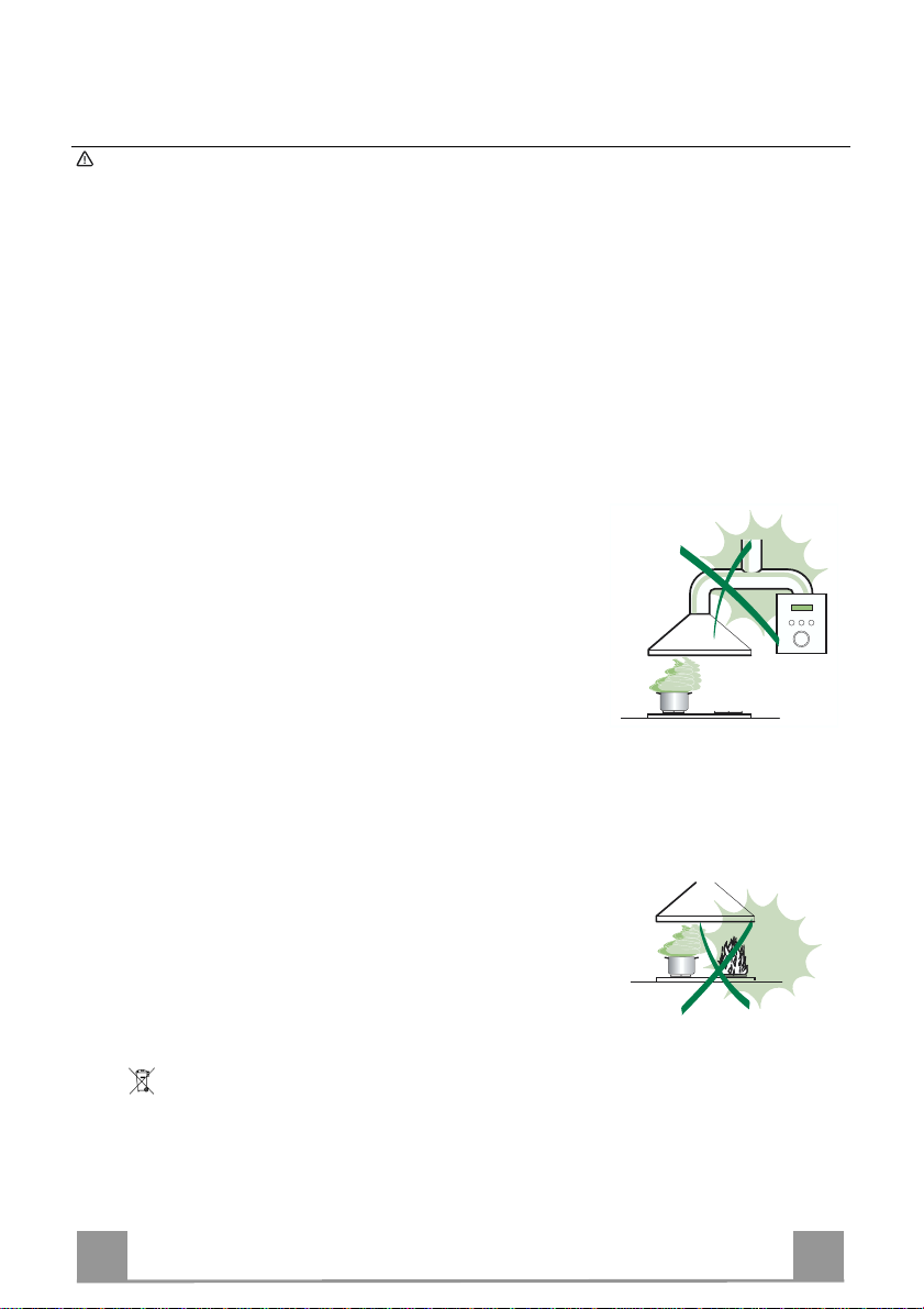
• Never leave high naked fla me s un der the ho od wh en it is in oper at i on.
• Adjust th e fl am e i n te nsity to direct it onto the bottom of t he pan only, making
sure that it does not engulf the sides.
• Dee p fat fryers must b e continuously m onitored durin g use: overheate d oil
can burst into flames.
• Do not flambè under the range hood; risk of fire
• This ap pliance is not i ntended for use by persons (includi ng children) with
reduced physical , sensory or mental capabilitie s, or lack of ex perience and
knowledge, unless th ey have been g iven su pervi sion o r in structi on con cern ing use of the appliance by a person responsible for their safety.
• Child re n sh ould be supervised to ensure that they do not play with the appliance.
MAINTENANCE
• Switch off or unplug the appliance from the m ains supply before carrying out
any maintenance work.
• Clean and/or replace the Filters after the specified time period (Fire hazard).
• Clean the hood using a damp cloth and a neutral liquid detergent.
The symbol on the product or on its packaging indicates that this product may not be treated
as household waste. Instead it shall be handed over to the applicable collection point for the
recycling of electrical and electronic equipmen t. By ensuring this pr o duct is disposed of correctly,
you will help prevent potential negative consequences for the environment and human health,
which could otherwise be caused by inappropriate waste handling of this product. For more
detailed information about recycling of this product, please contact your local city office, your
household waste disposal service or the shop where you purchased the product.
3
3
Page 4
EN
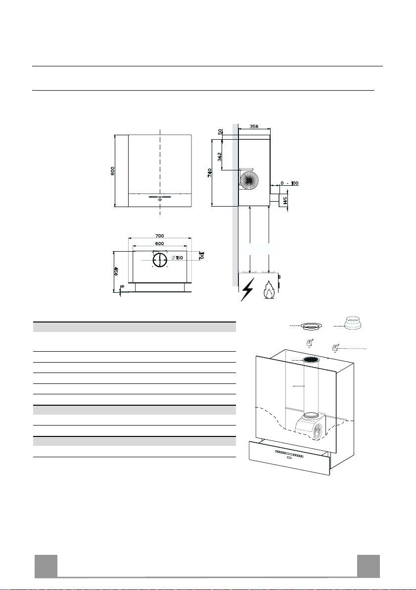
CHARACTERISTICS
Dimensions
Components
Ref. Q.ty Product components
1 1 Hood Body complete with: Controls, Light, Suction Unit,
Filters, Lower Duct
7 1 PVC Pipe (fitt ed)
8 1 Inclinable grid (fitted)
9 1 Reduction flange ø 150-120 mm
10 1 Metal cover
Ref. Q.ty Assembly components
11a 2 SB 12/10 Plugs
Q.ty Documents
1 Instruction Manual
Min.
650mm
Min.
650mm
10
8
7
9
11a
4
4
Page 5
EN
INSTALLATION
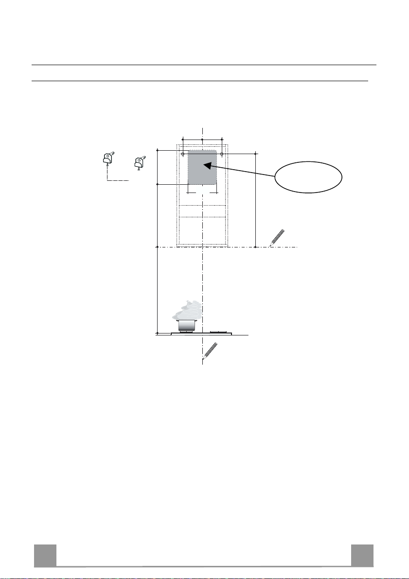
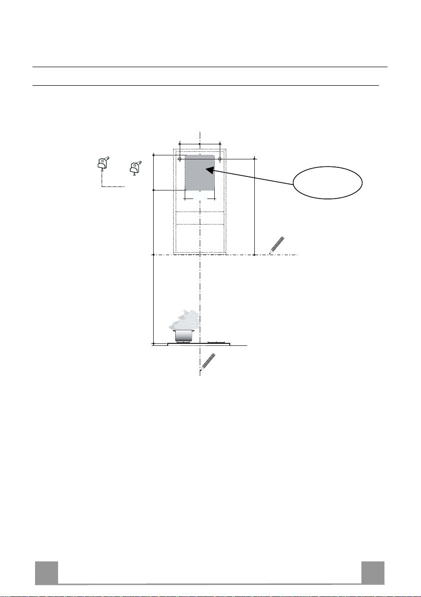
Boring the wall
If you want to use the hood in suction version with the air outlet at the back o f the hood, make
sure to follow the indications given below in the drawing for a correct boring operation of the air
outlet opening.
When installing the hood in recyclin g version it has to be taken into consideration th at space remaining between the hood and the upper limit (ceiling or self) is at least 8-10 cm.
On the wall, trace:
• a verti cal line up to th e ceiling or top limit, at the cen tre of the area where you int end to fit
the hood;
• a horizontal line at: 650 mm min. above the cooking hob;
• As shown, mark a reference point at 658 mm above the horizontal reference line, and at 230
mm to the right of the vertical reference line.
• Repeat this operation on the opposite side, checking levelling.
• Drill the points marked using a ø 12 mm bit
• Insert plugs with screws and brackets 11a in the holes then tighten them.
11a
442 275
650 mm min
250
230230
Rear air outlet
zone
658
5
5
Page 6
EN
Vr
11a
ø 150
9
ø 120
10
10
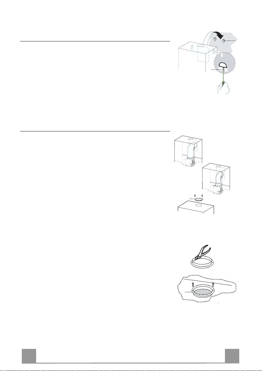
Hood body assembly
• Adjust the two screws Vr of brackets 11a, by just placing them
in position.
• Hook the hood body to the two brackets 11a.
• Pull the Comfort Panel to open it, remove the filters one by
one, push them towards the rear part of the unit and pull
downwards at the same time .
• From inside the hood body, tighten the screws Vr to level the
body.
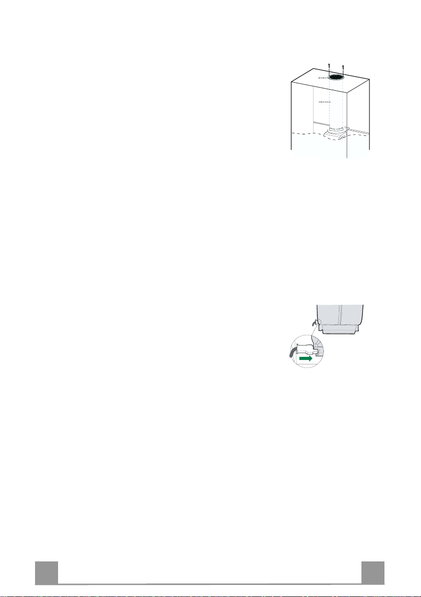
Connection
AIR OUTLET IN A DUCTING HOOD VERSION
When installing the hood in ducting version, basing on the installer’s choice, a rigid or a flexible pipe with a ø 150 or 120 mm
is used in order to connect the hood to the air outlet piping. The
pipe connection can be made on the upper part or on the rear side
of the hood.
Before connecting the hood to the air outlet ducting remove the
lateral air outlet grid 8 and the plastic tube 7. The adapting flange
9 has to be removed only in case the connecting diameter is 150.
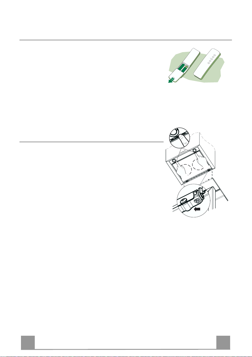
REAR AIR OU T L E T
• When drilling the air outlet hole in the wall proceed in accordance with the scheme in the part concerning the wall drilling.
• Use a pair of tongs when breaking t he rear ai r out let ho le in the
wall.
• In case the connection is made by using a ø 120 mm pipe insert
the reduction flange 9 on the hood body outlet.
• Fix the pipe with an adequate quantity of pipe clamps. This
material is not supplied together with the hood.
• Remove the charcoal filter if present.
• Fix the metal cover 10 to the upper air outlet hole of the hood
UPPER AIR OUTLET
• In case the connection is made by using a ø 120 mm pipe insert
• Use a pair of tongs when removing the cent ral part of the metal
• Fix the pipe with an adequate quantity of pipe clamps. This
• Remove the charcoal filter if present.
by using the screws supplied.
the reduction flange 9 on the hood body outlet.
cover 10. Fix the cover to the air outlet hole of the hood by us-
ing the screws supplied.
material is not supplied together with the hood.
6
6
Page 7

EN
8
7
AIR OUTLET IN A RECYCLING HOOD VERSION
• In case the components requested for the recycling functioning
have been removed earlier these have to be positioned again.
• Put the plastic tu be onto the flange 7.
• Pl ace the air outlet grid 8 on the air outlet. Make sure that the
position of the grid is correct.
• Make sure that charcoal filters have been placed inside the
hood.
ELECTRICAL CONNECTION
• Connect the hood to the mains through a two-pole switch having a contact gap of at least 3 mm.
• Re move the grease filters (see paragraph Maintenance) being
sure that the conn ector of the feeding cable is correctly inserted
in the socket placed on th e side of the fan.
7
7
Page 8
EN
USE
A
B
C
E
D
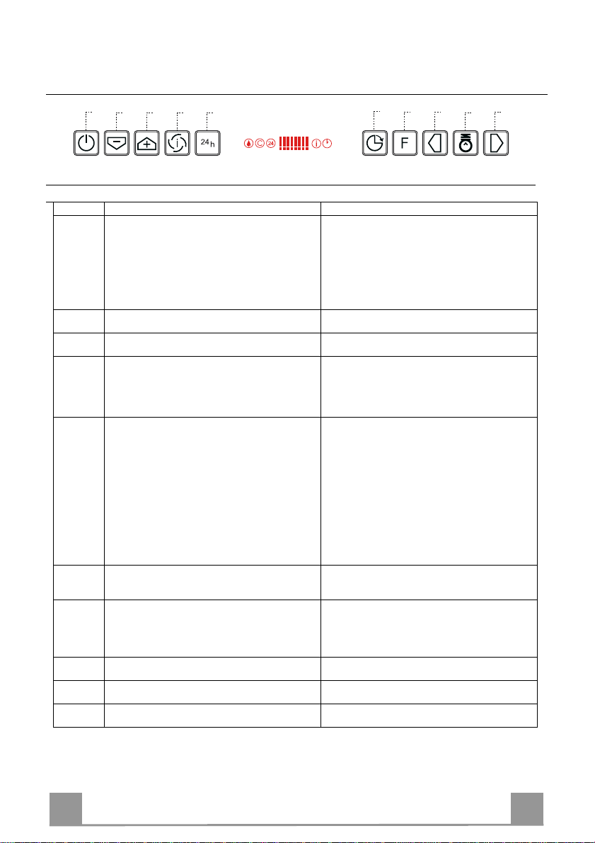
Control panel
Button Function Display
Carriage Closed: If the button is pressed and held for at
A
least 1.5 seconds, the Carriage opens, the Mo tor starts
at speed 2 and the Lights turn on at maximum intensity.
Carriage Open: If the button is pressed briefly the
Motor turns on/off. If the button is pressed and held for
at least 1.5 seconds, the Carriage closes and the Motor
switches off.
Decreases the working speed.
B
Only active with the Carriage open.
Increases the working speed.
C
Only active with the Carriage open.
Activates Intensive speed from any other speed, with
D
the exception of Delay. This speed is set to operate for
10 minutes, after which the system returns to the speed
that was set before. Suitable to deal with maximum
levels of cooking fumes.
Can only be activated if Intensive and Delay are Off.
E
Starts the Motor at a speed that allows suction of 100
m3/h for 10 minutes per hour, after which the Motor
will stop (24H function).
Carriage Closed: If the button is pressed briefly the
function is activated.
With the function active, if the Motor On/Off button is
pressed and held for at least 1.5 seconds, the f unction is
disabled, the Carriage opens, the Motor starts at speed 2
and the Lights turn on at maximum intensity.
Carriage Open: If the button is pressed briefly the
Motor switches off, the Carriage closes and the
function is activated.
Can only be activated if Intensive or 24H are Off.
F
Activates automatic switch-off with a 30’ delay.
Suitable to complete elimination of residual odours.
Performs a Reset of the Filter saturation alarm when
G
the Button is pressed for approximately 2 seconds with
Motor and Lights Off.
Decreases the intensity of the Lighting each time the
H
Button is pressed, in cycle.
Turns the lighting system on and off at maximum
I
intensity.
Increases the intensity of the Lighting each time the
L
Button is pressed, in cycle.
Keyboard Lock: it is possible to lock the keyboard, for exa mple when cleaning the Glass s urface, when the Hood has Motor and
Lights turned off.
Press D (Intensive) for approximately 5 Seconds to enable or disable the Keyboard Lock, which is always confirmed by a Beep
and an animation on the display Motor bar.
Displays the set speed, 2 LED indicators per speed.
N.B. If the Carriage blocks while closing due to
obstacles or the like, it will block for 1 second and will
then open again.
The number of lighted segments decreases.
The number of lighted segments increases.
The indicator I flashes and all the segments on the
Display are lit.
It is disabled by pressing the Button.
Displays 24 and the segments on the Display all light
up and then turn off one at a time in cycle.
It is disabled by pressing the Button or the Motor
On/Off button (button A).
Displays a flashing Clock symbol.
It is disabled by pressing the button or turning the
motor off.
After 100 hours in operation the Drop symbol is
displayed to indicate saturation of the Metal Grease
Filters.
After 200 hours in operation the letter
indicate saturation of the Activated Charcoal filters.
F
G
H
L
I
C is displayed to
8
8
Page 9
EN
MAINTENANCE
REMOTE CONTROL (OPTIONAL)
The appliance can be controlled using a remote control powered
by a 1.5 V carbon-zinc alkaline batteries of the standard LR03AAA type.
• Do not place the remote co ntrol near to heat sources.
• Used batteries must be disposed of in the proper manner.
Cleaning the Comfort Panels
• Pull the Comfort Panel to open it.
• Disconnect the panel from the hood canopy by sliding the fixing pin lever.
• The comfort panel must never be washed in a dishwasher.
• Clean the outside using a damp cloth and neutral liquid detergent.
• Clean the inside as well using a damp cloth and neutral detergent; do not use wet cloths or sponges, or jets of water; do not
use abrasive substances.
• When the above operation has been completed, hook the panel
back to the hood canopy and close it by turning the knob in the
opposite direction.
9
9
Page 10

EN 110
Metal grease filters
These can be washed in t he dishwasher, and need to be clean ed
whenever the Drop symbol appears on the display or at least
once every 2 months use, or more frequently if use is particularly
intensive.
Resetting the alarm signal
• Press button G and hold it for at least 2 seconds.
Cleaning the Filters
• If closed, open the Carriage by pressing button A and holding
for at least 1.5 seconds (see USE).
• Open the comfort panel.
• Remove the Filters one at a time, pushing them towards the
back of the unit and at the same time pulling downward.
• Wash the Filters without bending them, and leave them to dry
completely before replacing. (If the surface of the filter
changes colour as time goes by, this will have absolutely no
effect on the efficiency of the filter itself.)
• Replace, taking care to ensure that the handle faces forwards.
• Close the comfort panel.
Page 11
EN 111
A
B
Charcoal filter (recycling version)
This filter cannot be washed or regenerated. It must be replaced when the C appears on the
display or at least once every 4 months. The filter saturation alarm has to be activated already
before.
Activation of the alarm signal
• In the recycling version hoods the filter saturation alarm must be activated during the installation or later.
• Switch off the hood and the lights.
• Press the E-key for about 5 seconds until the last two segments of the motor LEDS are lit on
the display.
• By releasing the E-key the clock icon starts to flash.
• Within 3 seconds press the D-key to activate/ deactivate charcoal filter saturation alarm.
• C-symbol lit - charcoal filter saturation alarm ACTIVATED.
• C-symbol unlit - charcoal filter saturation alarm DEACTIVATED.
CHANGING THE ACTIVATED CHA RCOAL FI LTER
Resetting the alarm signal
• Press button G and hold it for at least 2 seconds.
Changing the Filter
• If closed, open the Carriage by pressing button A and holding
for at least 1.5 seconds (see USE).
• Open the comfort panel.
• Remove the grease filters.
• Remove the saturated Activated Charcoal Filters, as indicated
(A).
• Fit the new Filters, as indicated (B).
• Replace the metal grease filters.
• Close the comfort panel.
Lighting
LIGHT REPLACEMENT
20 W halogen light.
• Extract the lamp from the lamp holder by pulling gently.
• Replace with another of th e same type, makin g sure th at t he t wo
pins are properly inserted in the lamp holder socket holes.
Page 12
EN 112
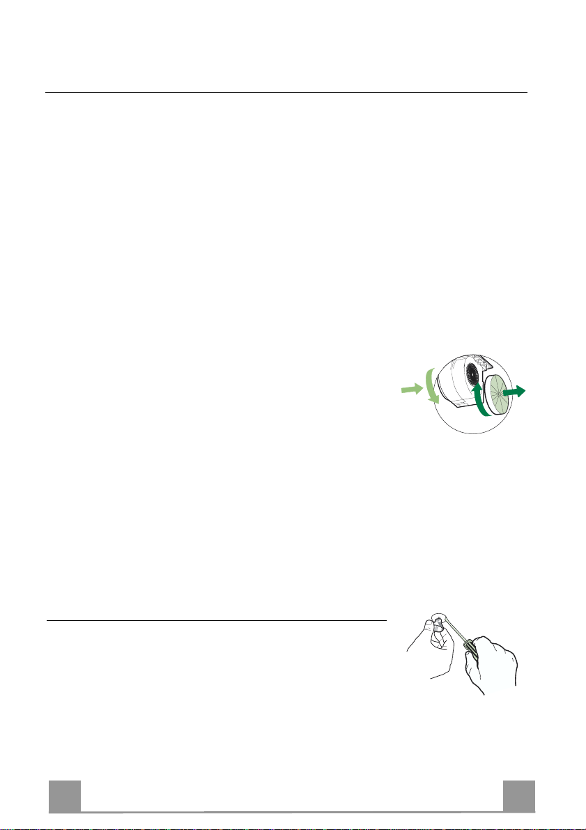
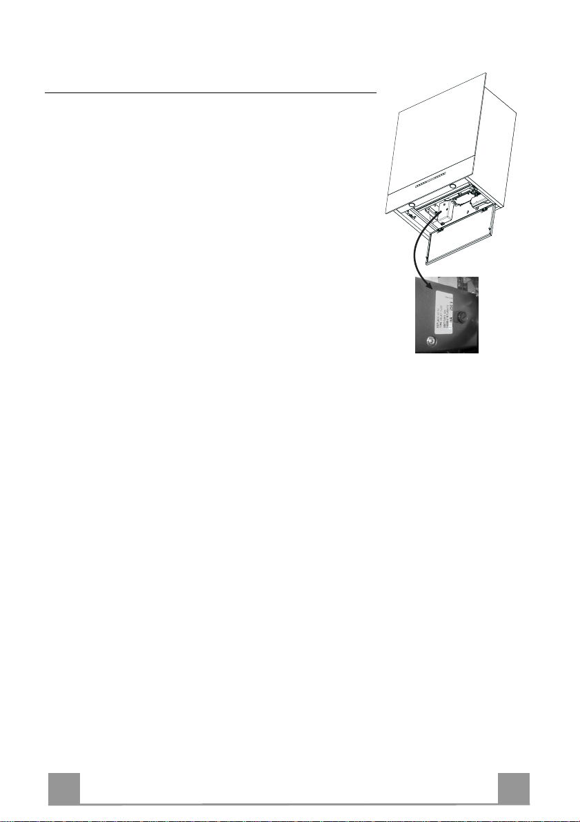
Replacing the fuser
• Open the comfort panel.
• Remove the grease filters.
• The fuser is placed u p on the right side. Turn the fuser holder
as indicated. Replace t he fuser with one having the sa me features.
• Put the fuser holder and grease filters into their place again.
Make sure that the hood functions correctly. In case the pan el
doesn’t work correctly it is necessar y to contact an authorized
technician.
Page 13
IT 113
Questo libretto di istruzioni per l'uso è previsto per più versioni dell' appare
c
chio.
CONSIGLI E SUGGERIMENTI
É possibile che siano descritti singoli particolari della dotazione, che non riguardano il Vostro apparec c hio.
INSTALLAZIONE
• Il produttore declina qualsiasi responsabilità per danni dovuti ad installazione non
corretta o non confor me alle regole d ell’art e.
• La distanza minima di sicurezza tra il Piano di cottura e la Cappa deve essere di
650 mm, (alcuni modelli possono esser e installati ad un’alt ezza inferiore, fare riferimento ai paragrafi i ngo mbro e i nst al laz ione) .
• Verificare che la tensione di rete corrisponda a quella riportata nella targhetta
posta all’interno della Cappa.
• Pe r Appare cchi in C lasse I
sca un corretto sc ar ic o a ter ra.
• Collegare la Cappa all’uscita dell’aria aspirata con tubazione di diametro pari o
superiore a 120 mm. Il percorso della tubazione deve essere il più breve possibile.
• Non collegare la Cappa a condotti di scarico dei fumi prodotti da combustione
(caldaie, caminet ti , ec c.) .
• Nel caso in cui nella stanza vengano utilizzati sia la Cappa che apparecchi non
azionati da energia elettrica (ad esempio apparecchi utilizzatori di gas), si deve
provvedere ad una aerazione sufficiente dell’ambiente. Se la cucina ne fosse
sprovvista, praticare un’apertura che comunichi con l’esterno, per garantire il richiamo d’aria pulita.
USO
• La Cappa è stata progettata esclusivamente per uso domestico, per abbattere gli
odori della cucina.
• Non fare mai uso improprio del la Cap pa.
• Non lasciare fiamme liber e a for te i ntens it à sott o la Cappa i n funz i one.
• Regolare sempre le fiamme in modo da evitare una evidente fuoriuscita laterale
delle stesse ri spet t o al fondo dell e p entol e.
• Controllare le friggit r ici durant e l’ us o: l ’ol io surr isc aldat o potr ebb e inf iammar s i.
• Non preparare alimenti fl ambè sot to l a c appa da cuc i na; per ic olo d'i nc endi o.
• Que sto appare cchio n on deve esse re utiliz zato da person e (bambini inclusi) con
ridotte capacità psichiche, sensoriali o mentali, oppure da persone senza esperienza e conoscenza, a meno che non siano controllati o istruiti all’uso
dell’apparecchio da person e r esponsabili della loro sicurezza.
• I bambini devono essere supervisionati per assicurarsi che non giochino con
l’apparecchio.
MANUTENZIONE
• Prima di procedere a qualsiasi operazione di manutenzione, disinserire la Cappa
togliendo la spina elettrica o spegnendo l’interruttore generale.
• Effettuare una scrupolosa e tempestiva manutenzione dei Filtri secondo gli intervalli consigliati (Rischio di incendio).
• Per la pulizia delle su pe rfici d e lla C a ppa è suffi cie n te u tiliz za re u n pa nn o umido e
detersivo liqui do neutr o.
a
accertarsi ch e l’imp ianto e lettrico dome stico ga ranti-
Il simbolo sul prodotto o sulla confezione indica che il prodotto non deve essere considerato
come un nor m ale rifiuto domes ti c o , m a d eve essere portat o n el p unto di raccolta a ppropriato per
il ricicl aggi o di a ppar ec c hi atur e el et tri che e d el et tro nic he. P r ovv edendo a smaltire questo prodotto in modo appropriato, si contribuisce a evitare potenziali conseguenze negative per l’ambiente
e per la salute, che potrebbero derivare da uno smaltimento inadeguato del prodotto. Per informazioni più dettagliate sul riciclaggio di questo prodotto, contattare l’ufficio comunale, il servizio
locale di smaltimento rifiut i o il negozio in cui è stato acqu istat o il prodot to .
Page 14

IT 114
CARATTERISTICHE
Ingombro
Componenti
Rif. Q.tà Componenti di Prodotto
1 1 Corpo Cappa completo di: Comandi, Luce, Gruppo
Ventilatore, Filtri, Camino I nferiore
7 1 Tubo PVC (Installato)
8 1 Griglia direzionata (Installata)
9 1 Flangia di Riduz ione ø 150-1 20 mm
10 1 Tappo
Rif. Q.tà Componenti di Installazione
11a 2 Tasselli SB 12/10
Q.tà Documentazione
1 Libretto Istruzioni
Min.
650mm
Min.
650mm
10
8
7
9
11a
Page 15
IT 115
Zona uscita aria
INSTALLAZIONE
Foratura Parete
Qualora si voglia collegare la cappa in versione aspirante, facendo uscire il tubo sulla parte posteriore, si ricorda che il foro di evacuazione dell’aria deve essere fatto seguendo le indicazione
di seguito riportat e nel disegno.
230230
11a
250
658
442 275
posteriore
650 mm min
Nel caso di installazione della cappa in versione filtrante, tenere in considerazion e che, sopra la
cappa, deve rimanere una distanza dal limite superiore (Soffitto o Mensola) di almeno 8-10 Cm.
Tracciare sulla Parete:
• una linea Verticale fino al soffitto o al limite superiore, al centro della zona prevista per il
montaggio della Cappa;
• una linea Orizzon tale a: 650 mm min. sopra il Piano di Cottura;
• Segnare come indicato, un punto di riferimento a 658 mm sopra la linea orizzontale di riferimento, e a 230 sulla destra della linea verticale di riferimento.
• Ripetere questa operazione dalla parte opposta, verificandone il livellamento.
• Forare ø 12 mm i punti segnati.
• Inserire i tasselli con vite e staffa 11a nei fori, avvitare.
Page 16

IT 116
Vr
11a
ø 150
9
ø 120
10
10
Montaggio Corpo Cappa
• Regolare le due viti Vr, delle staffe 11a, ad inizio corsa.
• Agganciare il corpo cappa alle 2 staffe 11a.
• Aprire il Comfort Panel tirandolo, togliere i Filtri uno alla volta, spingendoli verso la parte posteriore del gruppo e tirando
contemporaneamente verso i l basso.
• Dall’interno del corpo cappa agire sulle Viti Vr per livellare il
Corpo Cappa.
Connessioni
USCITA ARIA VERSIONE ASPIRANTE
Per installazione in Versione Aspirante collegare la Cappa alla
tubazione di usci ta per mezzo di un tubo rigido o flessibi le di ø
150 o 120 mm, la cui scelta è lasciata all'installatore. Il tubo può
uscire sia dalla parte superiore che posteriore della cappa.
Prima di procedere alle connessioni aspiranti rimuovere, qualora
non sia già stato fatto, la griglia direzionata 8 e il tubo in pvc 7.
La flangia di riduzione 9 va rimossa solo per effettuare collegamenti da ø 150.
USCITA POSTERIORE
• Si ricorda che p er effettuare il foro di evacuazi one va seguito
lo schema riportato nel paragrafo foratura parete.
• Rompere il foro di uscita posteriore con l’ausilio di una pinza.
• Per collegamento con tubo ø120 mm, inserire la Flangia di riduzione 9 sull'Uscita del Corpo Cappa.
• Fissare il tubo con adeguate fascette stringitubo. Il materiale
occorrente non è in dotazione.
• Togliere eventuali Filtri Antiodore al Carbone attivo.
• Fissare il Tappo 10 sull’Uscita Superiore della Cappa con le
USCITA SUPERIORE
• Per collegamento con tubo ø120 mm, inserire la Flangia di ri-
• Rimuovere la parte centrale del Tappo 10 con l’ausilio di una
• Fissare il tubo con adeguate fascette stringitubo. Il materiale
• Togliere eventuali Filtri Antiodore al Carbone attivo.
Viti in dotazione.
duzione 9 sull'Uscita del Corpo Cappa.
pinza e fissarlo sull’Uscita Superiore della Cappa con le Viti in
dotazione.
occorrente non è in dotazione.
Page 17
IT 117
8
7
USCITA ARIA VERSIONE FILTRANTE
• Qualora fossero stati rimossi riposizionare i componenti per
versione filtrante già installati.
• Inserire il tubo in pvc 7 sulla Flangia.
• Riavvitare la Griglia direzionata 8 sull’uscita dell’aria, facendo
attenzione che sia posizionata correttamente sul tubo.
• Assicurarsi della presenza dei Filtri antiodore al Carbone attivo.
CONNESSIONE ELETTRICA
• Collegare la Cappa all’Alimentazione di Rete interponendo un
Interruttore bipolare con apertura dei contatti di almeno 3 mm.
• Rimuovere i Filtri antigrasso (vedi par. “Manutenzione”) e assicurarsi che il connettore del Cavo di alimentazione sia correttamente inserito nella presa dell’Aspiratore
Page 18

IT 118
USO
A
B
C
E
D
Quadro comandi
Tasto Funzione Display
Carrello chiuso: Se il tasto viene premuto per al meno 1,5
A
Secondi, il Carrello si apre, il Motore si accende alla seconda velocità e le Luci si accendono alla massima intensità.
Carrello aperto: Se il tasto viene premuto brevemente il
Motore si accende/spegne. Se il tasto viene premuto per
almeno 1,5 Secondi, il Carrello si chiude e il Motore si
spegne.
Decrementa la velocità di esercizio.
B
Attivo solo a Carrello aperto.
Incrementa la velocità di esercizio.
C
Attivo solo a Carrello aperto.
Attiva la velocità Intensiva da qualsiasi velocità ad ecce-
D
zione del Delay, tale velocità è temporizzata a 10 minuti,
al termine del tempo il sistema ritorna alla velocità precedentemente impostata. Adatta a fronteggiare le massime
emissioni di fumi di cottura.
Attivabile solo se Intensiva e Delay sono Off.
E
Attiva il Motore ad una velocità che consente
un’aspirazione di 100 m
nati il Motore si ferma (Funzione 24H).
Carrello chiuso: Se il tasto viene premuto brevemente si
attiva la funzione.
Con funzione già attiva, se il tasto On/Off Motore viene
premuto per almeno 1,5 Secondi, la funzione si disabilita,
il Carrello si apre, il Motore si accende alla seconda velocità e le Luci si accendono alla massima intensità.
Carrello aperto: Se il tasto viene premuto brevemente il
Motore si spegne, il Carrello si chiude e si at tiva la funzione.
Attivabile solo se Intensiva o 24H sono Off.
F
Attiva lo spegnimento automatico ritardato di 30’. Adatto
per completare l’eliminazione di odori residui.
Effettua il Reset dell’allarme saturazione Filtr i premendo
G
il Tasto per circa 2 Secondi con Motore+Luci Off..
Decrementa l’intensità di Illuminazione ad ogni pressione
H
del Tasto in modo ciclico.
Accende e spegne l’impianto di illuminazione alla massi-
I
ma intensità.
Incrementa l’intensità di Illuminazione ad ogni pressione
L
del Tasto in modo ciclico.
3
/h per 10 minuti ogni ora, termi-
Comando Blocco Tastiera: è possibile bloccare la tastiera, ad esempio per effettuare la pulizia della superficie in Vet r o, quando la Cappa ha il Motore e le Luci spente.
Premendo per circa 5 Secondi il tasto D ( Intensiva ) si può abilita re o disabilit are il Blocco Tasti era che è
sempre confermato con un Beep e un’animazione sulla barra Motore del display.
Visualizza la velocità impostata 2 Led per velocità.
N.B. Se il Carrello si blocca durante la fase di chiusura,
causa ostacoli o altro, si blocca per 1 secondo per poi
tornare in fase di apertura.
Diminuiscono i segmenti accesi.
Aumentano i segmenti accesi.
Lampeggia I e i segmenti sul Display sono tutti accesi.
Si disattiva premendo il Tasto.
Visualizza 24 e i segmenti sul Display da tutti accesi si
spengono uno alla volta ciclicamente.
Si disattiva premendo il Tasto oppure On/Off Motore
(Tasto A).
Visualizza il simbolo di un Orologio che lampeggia.
Si disattiva premendo il tasto o spegnendo il Motore.
Dopo 100 ore di Funzionamento Visualizza il simbolo
Goccia per segnalare la saturazione dei Filtri Metallici.
Dopo 200 ore di Funzionamento Visualizza C per segna-
lare la saturazione dei Filtri al Carbone Attivo.
F
G
H
L
I
Page 19

IT 119
MANUTENZIONE
TELECOMANDO (OPZIONALE)
Questo apparecchio può essere c omandato per mezzo di un tel ecomando, alimentato con pile alcaline zinco-carbone da 1,5 V del
tipo standard LR03-AAA.
• Non riporre il telecomando in prossimità di fonti di calore.
• Non disperdere le pile nell’ambiente, depositarle negli appositi
contenitori.
Pulizia dei Comfort Panel
• Aprire il Comfort Panel tirandolo.
• Sganciare il pannello dal corpo cappa facendo scorrere
l’apposita leva del perno di fissaggio.
• Il comfort panel non va assolutamente lavato in lavastoviglie.
• Pulirlo esternamente con un panno umido e detersivo liquido
neutro.
• Pulirlo anche internamente utilizzando un panno umido e de-
tergente neutro; non utilizzare panni o spugne bagnate, né getti
d’acqua; non utilizzare sost anze abrasive.
• Ad operazione ultimata riagganciare il pannello al corpo cappa
e richiuderlo.
.
Page 20

IT 220
Filtri antigrasso metallici
Sono lavabili anche in lavastoviglie, e necessitano di essere lavati
quando sul display appare il simbolo Goccia o almeno ogni 2
mesi circa di utilizzo o più frequentemente, per un uso particolarmente intenso.
Reset del segnale di allarme
• Premere il tasto G per almeno 2 Secondi.
Pulizia Filtri
• Se chiusa, aprire il Carrello premendo per almeno 1,5 secondi
il Tasto A (Vedi USO).
• Aprire il comfort panel.
• Togliere i Filtri uno alla volta, spingendoli verso la parte poste-
riore del gruppo e tir ando contemporaneamente verso il basso.
• Lavare i Filtri evitando di piegarli, e lasciarli asciugare prima
di rimontarli. (Un’event uale cambiamento del colore dell a superficie del filtro, che potrebbe verificarsi nel tempo, non pregiudica assolutamente l’efficienza dello stesso.)
• Rimontarli facendo attenzione a mantenere la maniglia verso la
parte visibile esterna.
• Richiudere il comfort panel.
Page 21

IT 221
A
B
Filtri antiodore al Carbone attivo (Versione Filtrante)
Non è lavabile e non è rigenerabile, va sostituito quando sul display appare il simbolo C o almeno ogni 4 mesi. La segnalazione di Allarme va preventivamente attivata.
Attivazione del segnale di allarme
• Nelle Cappe in Versione Filtrante, la segnalazione di Allarme saturazione Filtri va attivata al
momento dell’installazione o successivamente.
• Spegnere le Luci e il Motore di aspirazione.
• Premere il tasto E per circa 5 Sec. fino all’accensione degli ultimi due segmenti e di tutta la
linea puntinata della barra Motore sul Display.
• Rilasciare il tasto E, l’icona “Orologio” inizia a lampeggiare.
• Entro 3 secondi premere il Tasto D per abilitazione / disabilitazione Filtri C.A.
• Accensione del simbolo C Allarme saturazione Filtro C.A. ATTIVATO
• Spegnimento del simbolo C Allarme saturazione Filtro C.A. DISATTIVATO
SOSTITUZIONE FILTRO ANTIODORE AL CARBONE ATTIVO
Reset del segnale di allarme
• Premere il tasto G per almeno 2 Secondi.
Sostituzione Filtro
• Se chiusa, aprire il Carrello premendo per almeno 1,5 secondi
il Tasto A (Vedi USO).
• Aprire il comfort panel.
• Togliere i Filtri antigrasso.
• Rimuovere i Filtri antiodore al Carbone attivo saturi, come in-
dicato (A).
• Montare i nuovi Filtri, come indicato (B).
• Rimontare i Filtri antigrasso.
• Richiudere il comfort panel.
Illuminazione
SOSTITUZIONE LAMPADE
Lampade alogene da 20 W
• Estrarre la Lampada dal Supporto.
• Sostituirla con una nuova di uguali caratteristiche, facendo attenzione ad inserire correttamente i due spinotti nella sede del
Supporto.
Page 22

IT 222
Sostituzione fusibile
• Aprire il comfort panel.
• Togliere i Filtri antigrasso.
• Il fusibile è posizionato in alto a destra, ruotare come indicato
il portafusibile e sostituire il fusibile con uno di uguali caratteristiche.
• Riposizionare il portafusibile e i filtri antigrasso, verificare il
corretto funzionamento della cappa. Nel caso l’anta continui a
non funzionare contatt are un Tecnico autorizzato.
Page 23

FR 223
CONSEILS ET SUGGESTIONS
La présente notice d'emploi vaut pour plusieurs versions de l'appareil. Elle peut conte-
nir des descriptions d'accessoir es ne fi gurant pas dan s votr e apparei l.
INSTALLATION
• Le fabricant décline toute responsabilité en cas de dommage dû à un e in st alla tion non
correcte ou non conforme aux règles de l ’ art.
• La distance minimale de sécurité entre le plan de cuisson et la hotte doit être de 650
mm au moins (certains modèles peuvent être installés à une hauteur inférieure : se reporter aux paragraphes « Encombrem ent » et « Instal lati on »).
• Vérifier que la tension du secteur correspond à la valeur qui figure sur la plaquette
apposée à l’intérieur de la hotte.
• Pour les Appareils appartenant à la Ière Classe, veiller à ce que la mise à la terre de
l’installation électrique domestique ait été effectuée conformément aux normes en vigueur.
• Connecter la hotte à la sort ie d’air aspiré à l’ aide d’une tuyauterie d’un diamètre égal ou
supérieur à 120 mm. Le parcours de la tuyaut eri e doit être le plus court possibl e.
• Ne pas connecter la hotte à des conduites d’évacuation de fumées issues d’une com-
bustion tel que (Chaudière, chemi née, et c…).
• Si vous utilisez des appareils qui ne fonctionnent pas à l’électricité dans la pièce ou est
installée la hotte (par exemple: des appareils fonctionnant au gaz), vous devez prévoir
une aération suffisante du milieu. Si la cuisine en est dépourvue, pratiquez une ouverture qui communique avec l’ext érieur pour garant ir l’infil trati on de l’ai r pur.
UTILISATION
• La hotte a été conçue exclusivement pour l’usage domestique, dans le but d’éliminer
les odeurs de la cuisine.
• Ne jamais utiliser abusivement la hotte.
• Ne pas laisser les flammes libres à forte intensité quand la hotte est en service.
• Toujours régler les flammes de manière à éviter toute sortie latérale de ces dernières
par rapport au fond des marmites.
• Contrôler les friteuses lors de l’utilisati on car l’huile sur chauff ée pourrai t s’ enfl ammer.
• Ne pas préparer d’aliments flambés sous la hotte de cuisi ne : risque d’ incendi e
• Cet appareil ne doit pas être utilisé par des personnes (y compris les enfants) ayant
des capacités psychiques, sensorielles ou mentales réduites, ni par des personnes
n’ayant pas l’expérience et la connaissance de ce type d’appareils, à moins d'être so us
le contrôle et la formation de personn es respo nsables de l eur sécuri té.
• Les enfants doivent être surveillés pour s'assurer qu'ils ne jouent pas avec l'appareil.
ENTRETIEN
• Avant de procéder à toute opération d’entretien, ret irer la hotte en retirant la fiche ou en
actionnant l’interrupteur général.
• Effectuer un entretien scrupuleux et en temps dû des Filtres, à la cadence conseillée
(Risque d’incendie).
• Pour le nettoyage des surfaces de la hotte, il suffit d’utiliser un chiffon humide et déter-
sif liquide neutr e.
Le symbole sur le produit ou son emballage indique que ce produit ne peut être traité comme
déchet ménager. Il doit plutôt être remis au point de ramassage concerné, se chargeant du recyclage du matériel électrique et électronique. En vous assurant que ce produit est éliminé correctement, vous favorisez la prévention des conséquences négatives pour l’environnement et la santé
humaine qui, sinon, seraient le résultat d’un traitement inapproprié des déchets de ce produit. Pour
obtenir plus de détails sur le recyclage de ce produit, veuillez prendre contact avec le bureau municipal de votre région, votre service d’élimination des déchets ménagers ou le magasin où vous avez
acheté le produit.
Page 24

FR 224
CARACTERISTIQUES
Encombrement
Composants
Réf. Q.té Composants du Produit
1 1 Corps de la Hotte comprenant: Commandes, Éclairage,
Groupe Ventil ateur, Filtres, Cheminée I nférieure.
7 1 Tuyau en PVC (Installé)
8 1 Grille orientable(Installée)
9 1 Flasque de Raccord ø 150-120 mm
10 1 Bouchon
Réf. Q.té Composants d’Installation
11a 2 Chevilles SB 12/10
Q.té Documentation
1 Manuel d’Instructions
Min.
650mm
Min.
650mm
10
8
7
9
11a
Page 25

FR 225
INSTALLATION
Perçage de la Paroi
Si on souhaite connecter la hotte dan s la version asp irante, en faisan t sortir le tuyau sur la partie
arrière, il ne faut pas oublier que le trou d’évacuation d e l’air doit être réalisé en suivan t les indications reportées ci-après dans le dessin.
230230
11a
250
658
442 275
Zone arrière éva-
cuation air
650 mm min
En cas d’installation de la hotte e n version filtrante, prendr e en considération le fait qu’il faud ra
laisser au moins 8-10 cm entre la hotte et le plafond ou toute autre limite supérieure (étagère).
Marquer sur la Paroi:
• une ligne Verticale jusqu’au plafond ou à la limite supérieure, au milieu de la zone prévue
pour le montage de la Hotte;
• une ligne Horizontale à: 650 mm min. sur les Plaques de Cuisson;
• Marquer comme indiqué un point de référence à 658 mm sur la ligne horizontale de réfé-
rence et à 230 mm à droite de la l ign e vert icale de référence.
• Répéter cette opération sur le côté opposé, en vérifiant le nivellement de celui-ci.
• Percer ø 12 mm les points marqués.
• Insérer les chevilles avec vis et bride 11a dans les trous, puis visser.
Page 26

FR 226
Vr
11a
ø 150
9
ø 120
10
10
Montage du Corps de la Hotte
• Régler les deux vis Vr, des brides 11a, sans les visser à fond.
• Accrocher le corps de la hotte aux 2 brides 11a.
• Ouvrir le Confort Pannel en le tirant, retirer les Filtres, l’un
après l’autre, en les poussant vers la p artie arrière du groupe et
en tirant simultanément vers le bas.
• Depuis l’intérieur du corps de la hotte, intervenir sur les Vis Vr
pour effectuer le nivellement du Corps de la Hotte.
Connexions
SORTIE D’EVACUATION DE L’AIR VERSION ASPIRANTE
Pour l’installation en Version Aspirante, connecter la Hotte à la
conduite d’évacuation au moyen d’un tuyau rigide ou flexible de
ø 150 ou 120 mm, dont le choix sera laissé à l’installateur. Le
tuyau peut sortir aussi bien depuis la partie supérieure que depuis
l’arrière de la hotte.
Avant d’effectuer les connexions d’aspiration il faut retirer, si
cela n’a pas encore été fait, la grille orientable 8 et le tuyau en
pvc 7. La flasqu e de raccord 9 doit être retirée uniquement pour
effectuer les connexions de ø 150.
SORTIE ARRIÈRE
• Nous rappelons que pour percer le trou d’évacuation, il faut
suivre le schéma reporté dans le paragraphe relatif au perçage
de la paroi.
• Dégager le trou de sortie arrière à l’aide d’une pince.
• Pour la connexion avec un tuyau de ø120 mm, insérer la Flasque de raccord 9 sur la Sortie du Corps de la Hotte.
• Fixer le tuyau au moyen de colliers serre-tube appropriés. Le
matériau nécessaire n’est pas fou rni avec l’appareil.
• Retirer les éventuels Filtres Anti-odeur au Charbon actif.
• Fixer le Bouchon 10 sur la Sortie Supérieure de la Hotte au
SORTIE SUPÉRIEURE
• Pour la connexion avec tuyau de ø120 mm, insérer la Flasque
• Retirer la partie centrale du Bouchon 10 à l’aide d’une pince et
• Fixer le tuyau au moyen de colliers serre-tube appropriés. Le
• Retirer les éventuels Filtres Anti-odeur au Charbon actif.
moyen des Vis fournies avec l’appareil.
de raccord 9 sur la Sortie du Corps de la Hotte.
fixer celui-ci sur la Sortie Supérieu re de la Hotte au moyen des
Vis fournies avec l’appareil .
matériau nécessaire n’est pas fou rni avec l’appareil.
Page 27

FR 227
8
7
ÉVACUATION DE L’AIR VERSION FILTRANTE
• Si les composants pour la version filtrante ont été retirés, les
remettre en place.
• Insérer le tuyau en pvc 7 sur la Flasque.
• Revisser la Grille orientable 8 sur la sortie d’évacuation de
l’air, en veillant à ce qu’elle soit positionnée correctement sur
le tuyau.
• S’assurer que les Filtres anti-odeur au Charbon actif soient présents.
BRANCHEMENT ELECTRIQUE
• Brancher la hotte sur le secteur en interpo sant un interrupteur
bipolaire avec ouvertu re des contacts d’au moins 3 mm.
• Enlever les filtres à graisse (voir § "Entretien") et s'assurer que
le connecteur du câbl e d'al imentati on so it bien bran ché dan s la
prise du diffuseur.
Page 28

FR 228
UTILISATION
A
B
C
E
D
Tableau de commandes
Touche Fonction Affichage
Chariot fermé : Si la touche est enfoncée pendant au moins
A
1,5 sec., le chariot s’ouvre, le moteur s’allume en deuxième
vitesse et les lumières s’allument à intensité maximale.
Chariot ouvert : Si la touche est enfoncée brièvement, le
moteur s’allume ou s’éteint. Si la touche est enfoncée pendant
au moins 1,5 sec., le chariot se ferme et le moteur s’éteint.
Réduit la vitesse d’exercice.
B
Actif seulement avec le chariot ouvert.
Augmente la vitesse d’exercice.
C
Actif seulement avec le chariot ouvert.
Active la vitesse intensive à partir de n’importe quelle vitesse,
D
à l’exception de la fonction de Retard. Cette vitesse est
programmée pour durer 10 minutes, après quoi le système
retourne à la vitesse réglée au préalable.
pour faire face aux pointes d’émission de fumées de cuisson.
Activable seulement si les fonctions Intensif et Retard sont
E
désactivées.
Active le moteur à une vitesse qui permet une aspiration de
3
100 m
/h pendant 10 minutes toutes les heures ; puis le moteur
s’arrête (fonction 24 h).
Chariot fermé : La fonction est activée en enfonçant
brièvement la touche.
Lorsque la fonction est déjà active et la touche Marche / Arrêt
est enfoncée pendant au moins 1,5 sec., la fonction se
désactive et le chariot s’ouvre ; le moteur s’allume en
deuxième vitesse et les lumières s’allument à intensité
maximale.
Chariot ouvert : Si la touche est enfoncée brièvement, le
moteur s’éteint, le chariot se ferme et la fonction s’active.
Activable seulement si les fonctions Intensif ou 24 H sont
F
désactivées.
Active l’extinction automatique avec un délai de 30 minutes.
Indiqué pour compléter l’élimination des odeurs résiduelles.
Effectue la Réinitialisation de l’alarme de saturation des
G
filtres en appuyant sur la touche pendant environ 2 secondes
avec moteur - éclairage désactivés.
Réduit l’intensité de l’éclairage à chaque pression de la touche
H
de façon cyclique.
Allume et éteint l’éclairage à intensité maximale.
I
Augmente l’intensité de l’éclairage à chaque pression de la
L
touche de façon cyclique.
Commande de blocage du clavier : il est possible de bloquer le clavier, par exemple pour effectuer le nettoyage des surfaces en
verre, lorsque le moteur et les lumières de la hotte sont éteints.
En appuyant pendant environ 5 secondes sur la touche D (Intensif), on peut activer ou désactiver le blocage du clavier : la
commande est toujours confirmée par un bip et par une animation sur la barre du moteur d’affichage.
Fonction indiquée
Affiche la vitesse de réglage, 2 témoins par vitesse.
N.B. Si le chariot se bloque en phase de fermeture
en raison d’un obstacle ou pour quelque autre motif,
il se bloque pendant 1 seconde avant de repartir en
phase d’ouverture.
Les segments allumés diminuent.
Les segments allumés augmentent.
Le I clignote et les segments sur l’affichage sont
tous allumés.
Désactivé en appuyant sur la touche.
Affiche 24 et les segments sur l’affichage, d’abord
tous allumés, s’éteignent un à un, par cycles.
Désactivable en appuyant sur la touche ou le bouton
Marche / Arrêt du moteur (touche A).
Affiche le symbole d’une horloge clignotante.
Pour désactiver, appuyer sur la touche ou éteindre le
moteur.
Au bout de 100 heures de fonctionnement, affiche le
symbole de Goutte pour signaler la saturation des
filtres métalliques.
Au bout de 200 heures de fonctionnement, affiche C
pour signaler la saturation des filtres au charbon
actif.
F
G
H
L
I
Page 29

FR 229
ENTRETIEN
TELECOMMANDE (FOURNIE SUR DEMANDE)
Il est possible de commander cet appareil au moyen d’une télécommande, alimentée avec des piles alcalines zinc-charbon 1,5 V
du type standard LR03-AAA.
• Ne pas ranger la télécommande à proximité de sources de chaleur.
• Ne pas jeter les piles; il faut les déposer dans les récipients de
récolte spécialement prévus à cet effet.
Nettoyage des Confort Panel
• Ouvrir le Confort Panel, en tirant ce dernier.
• Décrocher le panneau du corps de la hotte, en faisant coulisser
le levier du goujon de fixation spécialement prévu.
• En aucun cas, le confort panel ne doit être lavé au lavevaisselle.
• Le nettoyer à l’extérieur à l’aide d’un chiffon humide et d’un
détergent liquide neutre.
• Le nettoyer également à l’intérieur, en utilisant un chiffon humide et un détergent neutre; ne pas utiliser des chiffons ou des
éponges mouillées, ni des jets d’eau; ne pas utiliser des substances abrasives.
• Lorsque l‘opération est ach evée, accrocher à nouveau le panneau sur le corps de la hotte, puis le refermer, en tournant le
bouton dans le sens inverse par rapport à l’ouverture.
Page 30

FR 330
Filtres à graisse métalliques
Ils sont lavables même en lave-vaisselle et doivent être lavés
chaque fois que le symbol e Goutte s’affiche ou au moins tous les
2 mois environ, voire plus souvent, en cas d’utilisation
particulièrement intensive.
Remise à zéro du signal d'alarme
• Appuyer sur la touche G pendant au moins 2 secondes.
Nettoyage des filtres
• Si la porte est fermée, ouvrir le chariot en appuyant sur la
touche A pendant environ 1.5 seconde (Voir EMPLOI).
• Ouvrir le panneau Confort.
• Enlever les filtres un à un en les poussant vers l’arrière du
groupe tout en tirant simultanément vers le bas.
• Laver les filtres sans les plier et les laisser sécher avant de les
remonter (tout changement de couleur sur la surface du filtre,
susceptible de se produire avec le temps, ne nuit en rien à
l’efficacité de ce dernier).
• Les remonter en faisant attention à maintenir la poignée vers la
partie visible externe.
• Refermer le panneau Confort.
Page 31

FR 331
A
B
Filtres anti-odeur au charbon actif (version filtrante)
Il ne peut être ni lavé ni récupéré, il faut le changer quand le symbole C s’affiche ou au moins
tous les 4 mois. Il faut tout d’abord activer le signal d’alarme.
Activation du signal d’alarme
• Pour les hottes en version filtrante, l’alarme indiquant la saturation des filtres doit être activée au moment de l’installation ou ultérieurement.
• Éteindre les lumières et le moteur d’aspiration.
• Appuyer sur la touche E pendant 5 sec. environ, jusqu’à ce que les deux derniers segments
et toute la ligne en pointillés de la barre Moteur s’allument sur l’afficheur.
• Relâcher la touche E, l’i cône “Horloge” commencera à clignoter.
• Appuyer sur la touche D dans les 3 secondes qui s uivent pour activer/désactiver les filtres
au C.A.
• Le symbole C s’allume : alarme de saturation du filtre au C.A. ACTIVÉE
• Le symbole C s'éteint : alarme de saturation du filtre au C.A. DÉSACTIVÉE
REMPLACEMENT DU FILTRE AN TI-OD EUR AU C HARB ON A C TIF
Remise à zéro du signal d'alarme
• Appuyer sur la touche G pendant au moins 2 secondes.
Remplacement du filtre
• Si la porte est fermée, ouvrir le chariot en appuyant sur la tou-
che A pendant environ 1.5 seconde (Voir EMPLOI).
• Ouvrir le panneau Confort.
• Retirer les filtres à graisse.
• Enlever les filtres anti-odeur au charbon actif saturés, comme
indiqué (A).
• Monter les nouveaux filtres, comme indiqué (B).
• Remonter les filtres à graisse.
• Refermer le panneau Confort.
Eclairage
Lampe halogène de 20 W.
• Sortir la Lampe de la Douille en exerçant une légère traction.
• Remplacer par une nouvelle lampe possédant les mêmes caractéristiques, en veillant à ce que les deux fiches soient correctement insérées dans le logement de la Douille.
REMPLACEMENT LAMPES
Page 32

FR 332
Remplacement du fusible
• Ouvrir le panneau Confort.
• Retirer les filtres à graisse.
• Le fusible est situé en haut à droite ; tourner le porte-fusible
selon les indications fourni es et remplacer le fusible avec un
autre fusible ayant les mêmes caractéristiques.
• Remettre le porte-fusible en place ainsi que les filtres à graisse,
vérifier que la hotte fonctionne bien. Dans le cas où la porte
continue à ne pas fonctionner, contacter un technicien autorisé.
Page 33

DE 333
EMPFEHLUNGEN UND HINWEISE
Diese Gebrauchsanleitung gilt für mehrere Geräte-Ausführungen. Es ist möglich, dass
einzelne Ausstattungsmerkmale beschrieben sind, die nicht auf Ihr Gerät zutreffen.
MONTAGE
• Der Hersteller haftet nicht für Schäden, die auf eine fehlerhafte und unsachgemäße Mon-
tage zurückzuführen sind.
• Der minimale Sicherheitsabstand zwischen Kochmulde und Haube muss 650 mm betra-
gen (einige Modelle können an einer geri ngeren Höhe i nstalli ert werden, bezi ehen Si e sich
dazu auf den Absatz Raumbedarf und Installation).
• Prüfen, ob die Netzspannung mit dem Wert auf dem im Haubeninneren angebrach-
ten Schild übereinstimmt.
• Bei Geräten der Klasse I ist sicherzustellen, dass die elektrische Anlage des Wohnha uses
über eine vorschriftsmäßige Erdung verfügt.
• Das Anschlussrohr der Haube zur Luftaustrittsöffnung muss einen Durchmesser von 120
mm oder darüber aufweisen. Der Rohrverlauf muss so kurz wie möglich sein.
• Die Haube darf an keine Entlüftungsschächte angeschlossen werden, in die Verbren-
nungsgase (Heizkessel, Kamine usw.) geleitet werden.
• Werden im Raum außer der Dunstabzugshaube andere, nicht elektrisch betriebene (z.B.
gasbetriebene) Geräte verwendet, muss für eine ausreichende Belüftung gesorgt werden.
Sollte die Küche diesbezüglich nicht entsprechen, ist an einer Aussenwand eine Öffnung
anzubringen, die Frischluftzufuhr gewährleistet.
BEDIENUNG
• Die Dunstabzugshaube ist ausschließlich zum Einsatz im privaten Haushalt und zur
Beseitigung von Küchengerüchen vorgesehen.
• Unsachgemäßer Einsatz der Haube ist zu unterlassen.
• Große Flammen bei eingeschalteter Haube niemals unbedeckt lassen.
Achtung! Große Flammen bei ei ngesc hal tete r Haube niemals unbed eckt lasse n.
• Die Intensivität der Flamme ist so zu regulieren, dass sie den Topfboden nicht überragt.
Achtung! Frittiergeräte müssen während des Gebrauchs stets beaufsichtigt wer-
den: Überhitztes Öl kann sich entzünden.
• Frittiergeräte müssen während des Gebrauchs stets beaufsichtigt werden: überhitztes Öl
kann sich entzünden.
• Keine flambierten Speisen unter der Abzugshaube zubereiten: Brandgef ahr.
• Dieses Gerät darf nicht von Personen, auch Kindern, mit verminderten psychischen, sen-
sorischen und geistigern Fähigkeiten, oder von Personen ohne Erfahrung und K ennt nisse
benutzt werden, sofern sie nicht von für ihre Sicherheit verantwortlichen Personen beaufsichtigt und beim Gebrauch des Geräts angeleitet werden.
• Kinder dürfen sich nicht unbeaufsichtigt in der Nähe des Geräts aufhalten und auf keinen
Fall mit dem Gerät spielen.
WARTUNG
• Bevor Wartungsarbeiten durchgeführt werden, muss die Stromzufuhr zur Haube unterbro-
chen werden, indem der Stecker gezogen oder der Hauptschalter abgeschaltet wird.
• Bei der Filterwartung müssen die vom Hersteller empfohlenen Zeiträume zum Austauschen
der Filter genauestens eingehalten werden (Brandgefahr).
• Zur Reinigung der Haubenflächen Wir empfehlen ein feuchtes Tuch und ein mildes Flüssig-
reinigungsmittel.
• Bitte keine Reinigungsmittel mit Scheuermittel verwenden. Die Oberfläche wird damit
verkratzt.
Das Symbol auf dem Produkt oder seiner Verpackung weist darau f hin, dass dieses Produkt nicht als
normaler Haushaltsabfall zu behandeln ist, sondern an einem Samme lpunkt für das Recycling vo n elektrischen und elektronischen Geräten abgegeben werden muss. Durch Ihren Beitrag zum korrekten Entsorgen
dieses Produkts schützen Sie die Umwelt und die Gesundheit Ihrer Mitmenschen. Umwelt und Gesundheit
werden durch falsches Entsorgen gefährdet. Weitere Informationen über das Recycling dieses Produkts
erhalten Sie von Ihrem Rathaus, Ihrer Müllabfuhr oder dem Geschäft, in dem Sie das Produkt gekauft haben.
Page 34

DE 334
CHARAKTERISTIKEN
Platzbedarf
Komponenten
Bez. Menge Produktkomponenten
1 1 Haubenkörper komplett mit: Steuerungen, Beleuch-
tung, Ventilatorgruppe, Filter, unterem Kamin
7 1 PVC-Rohr (installiert)
8 1 Luftstromrichtungsgitter (installiert)
9 1 Reduktionsflansch ø 150- 120 mm
9 1 Deckel
Bez. Menge Installationskomponenten
11a 2 Dübel SB 12/10
Menge Dokumentation
1 Betriebsanleitung
Min.
650mm
Min.
650mm
10
8
7
9
11a
Page 35

DE 335
MONTAGE
Bohren der Wand
Soll die Haube in Abluftversion angeschlossen werden, indem das Rohr an der Rückseite ausgeleitet wird, so muss die Abzugsöffnung gemäß den Angaben in der folgenden Zeichnung ausgeführt werden.
230230
11a
442 275
250
Bereich Luftau-
stritt hinten
658
650 mm min
Bei Montage der Haube in Umluftversio n darauf achten, dass oberhalb der Haube ein Abstand
von mindestens 8-10 cm zur oberen Begrenzung (Decke oder Brett) einzuhalten ist.
Achtung: Bitte beachten Sie bei der Montage das Gewicht der kompletten Haube. Die Tragfä-
higkeit der Decke oder alternativ der Trägerplatte für diese Zugbelastung muss vor der Montage geprüft und gegebenenfalls durch die Anbringung von geeigneten Befestigungs- oder
Stabilisierungselementen hergestellt werden. Kann eine hinreichende Tragfähigkeit nicht sichergestellt werden, ist von einer Montage abzusehen.
An der Wand anzeichnen:
• eine senkrechte Linie bis zur Decke oder zum oberen Rand in der Mitte des Installationsbe-
reichs der Haube,
• eine horizontale Linie mindestens 650 mm oberhalb der Kochmulde.
• Wie angegeben 658 mm oberhalb der waagrechten Bezugslinie und 230 mm rechts von der
senkrechten Bezugslinie einen Punkt kennzeichnen.
• Diesen Vorgang an der gegenüberliegenden Seite wiederholen und die Ausrichtung überprü-
fen.
• Die gekennzeichneten Punkte mit einem Bohrer ø 12 mm bohren.
• Die Dübel mit Schraube und Bügel 11a in die Bohrungen einfügen und festschrauben.
Page 36

DE 336
Vr
11a
ø 150
9
ø 120
10
10
Montage des Haubenkörpers
• Die beiden Schrauben Vr der Bügel 11a so regulieren, dass sie
nur bis zum Gewindebeginn eingeschraubt sind.
• Den Haubenkörper bei den 2 Bügeln 11a einhaken.
• Das Comfort Panel durch Herausziehen öffnen. Die Filter einzeln entnehmen, indem sie zur Rückseite der Gruppe geschoben und gleichzeitig nach unten gezogen werden.
• Vom Haubeninneren her den Haubenkörper mit Hilfe der
Schrauben Vr ausrichten.
Anschlüsse
LUFTAUSTRITT AB LUFTVERSION
Für die Installation als Abluftversion die Haube mittels eines
starren oder flexiblen Rohrs mit ø 150 oder 120 mm, das vom
Installateur ausgewählt wird, an die Ableitung anschließen. Das
Rohr kann sowohl an der Oberseite, als auch an der Unterseite
der Haube austreten.
Vor dem Anschließen der Saugleitungen das Umlenkgitter 8 und
das PVC-Rohr 7 ausbauen, falls dies noch nicht geschehen ist.
Der Reduzierflansch 9 wird nur ausgebaut, um die Anschlüsse
mit ø 150 auszuführen.
HINTERER LUFTAUSTRITT
• Für die Erstellung der Auslassöffnung ist das Schema zu befolgen,
welches im Absatz über den Wandauslass aufgeführt ist.
• Die hintere Austrittsöffnung mit Hilfe einer Zange aufbrechen.
• Für den Anschluss mit einem Rohr mit ø 120 mm den Reduzierflansch 9 am Austritt am Haubenkörper einsetzen.
• Das Rohr mit passenden Rohrschellen fixieren. Das benötigte Material ist nicht im Lieferumfang enthalten.
• Eventuelle Aktivkohlefilter zur Geruchsbindung aus bauen.
• Den Verschlussdeckel 10 mit den mitgelieferten Schrauben am
oberen Luftaustritt der Haube befestige n.
OBERER LUFTAUSTRITT
• Für den Anschluss mit einem Rohr mit ø 120 mm den Reduzier-
• Den mittleren Teil des Verschlussdeckels 10 mit Hilfe einer Zange
• Das Rohr mit passenden Rohrschellen fixieren. Das benötigte Ma-
• Eventuelle Aktivkohlefilter zur Geruchsbindung aus bauen.
flansch 9 am Austritt am Haubenkörper einsetzen.
abnehmen und mit den mitgelieferten Schrauben am oberen Luft-
austritt der Haube befestigen.
terial ist nicht im Lieferumfang enthalten.
Achtung! Alle Querschnittänderungen oder Richtungsände-
rungen des Abluftkanals reduzieren die Le istung der Haube.
Page 37

DE 337
8
7
LUFTAUSTRITT BEI DER FILTERVERS ION
• Falls die bereits installierten Komponenten für die Filterversion ausgebaut wurden, müssen si e wied er ei ngebaut werden.
• Das PVC-Rohr 7 am Flansch aufstecken.
• Das Umlenkgitter 8 wieder am Luftaustritt anschrauben und
dabei darauf achten, dass es korrekt am Rohr positioniert ist.
• Sicherstellen, ob der Aktivkohlefilter zur Geruchsbindung vorhanden ist.
Elektroanschluss
Vor der Installation die Netzspannung durch herausdrehen der
Sicherung oder ausschalten des Hauptschalters s tromlos machen.
• Bei Anschluss der Haube an das Stromnetz muss ein
zweipoliger Schalter mit einem Öffnungsweg von
mindestens 3 mm zwischengeschaltet werden.
• Entfernen Sie die Fettfilter (s. Abschnitt „Wartung“) und
versichern Sie sich, daß die Kabel verbindung in die Steckdose des Gebläses einwandfrei eingesteckt wird.
Achtung: Das Gerät nur an die Netzspannung die im Typen-
schild angegeben ist anschließen.
Page 38

DE 338
BEDIENUNG
A
B
C
E
D
Schalttafel
Taste Funktion Display
Schlitten eingefahren: Wird die Taste mindestens 1,5 Sekunde
A
gedrückt, wird der Schlitten ausgefahren, der Motor schaltet auf die
zweite Gebläsestufe und die Lichter leuchten bei maximaler
Intensität.
Schlitten ausgefahren: Bei kurzem Drücken der Taste schaltet sich
der Motor ein oder aus. Wird die Taste mindestens 1,5 Sekunden
gedrückt, wird der Schlitten eingefahren und der Motor geht aus.
Vermindert die Betriebsgeschwindigkeit.
B
Nur bei ausgefahrenem Schlitten aktiv.
Erhöht die Betriebsgeschwindigkeit.
C
Nur bei ausgefahrenem Schlitten aktiv.
Aktiviert von jeder Geschwindigkeit aus, mit Ausnahme von De-
D
lay, die Intensivgeschwindigkeit, die auf 10 Minuten zeitgeregelt
ist. Nach Ablauf dieser Zeit kehrt das System zu der zuvor
eingestellten Geschwindigkeit zurück. Für die Beseitigung von sehr
intensiven Kochdünsten geeignet.
Nur aktivierbar, wenn Intensivgeschwindigkeit und Delay auf Off
E
eingestellt sind.
Aktiviert den Motor bei einer Geschwindigkeit, die eine Absaugleistung von 100 m
ermöglicht, nach dessen Ablauf hält der Motor an (Funktion 24H).
Schlitten eingefahren: Bei kurzem Drücken der Taste wird die
Funktion aktiviert.
Wird bei bereits aktiver Funktion die Taste On/Off Motor mindestens 1,5 Sekunde gedrückt, wird die Funktion deaktiviert, der
Schlitten wird ausgefahren, der Motor schaltet auf die zweite Gebläsestufe und die Lichter leuchten bei maximaler Intensität.
Schlitten ausgefahren: Bei kurzem Drücken der Taste geht der
Motor aus, der Schlitten wird eingefahren und die Funktion aktiviert.
Nur aktivierbar, wenn Intensivgeschwindigkeit oder 24H auf Off
F
eingestellt sind.
Aktiviert das automatische Ausschalten mit einer Verzögerung von
30’. Ermöglicht die Beseitigung von Restgerüchen.
Führt durch ca. 2 Sekunden langes Drücken der Taste bei Mo-
G
tor+Beleuchtung auf Off ein Reset des Filtersättigungsalarms aus.
Vermindert bei jedem Drücken der Taste zyklisch die Intensität der
H
Beleuchtung.
Schaltet die Beleuchtungsanlage auf höchster Intensitätsstufe ein
I
und aus.
Erhöht bei jedem Drücken der Taste zyklisch die Intensität der
L
Beleuchtung.
Steuerbefehl Tastatursperre: Die Tastatur lässt sich z.B. zur Reinigung der Glasscheiben sperren, wenn Motor und Beleuchtung der
Haube ausgeschaltet sind.
Zum Aktivieren oder Deaktivieren der Tastatursperre die Taste D (Intensivgeschwindigkeit) ca. 5 Sekunden lang drücken. Der
Vorgang wird immer durch einen Piepton und die Motorbalkenanzeige am Display bestätigt.
3
/h für die Dauer von 10 Minuten pro Stunde
F
G
H
Zeigt mittels 2 LEDs die eingestellte Gebläsestufe an.
NB: Wenn der Schlitten während des Einfahrens
klemmt oder behindert, blockiert er sich 1 Sekunde lang und kehrt dann zur Ausfahrphase
zurück.
Die leuchtenden Segmente nehmen ab.
Die leuchtenden Segmente nehmen zu.
I blinkt und alle Segmente auf dem Display
leuchten.
Wird durch Drücken der Taste ausgeschaltet.
Zeigt 24 an und alle auf dem Displa y an gezeigten
Segmente verlöschen nacheinander.
Wird durch Betätigen der Taste oder On/Off des
Motors (Taste A) deaktiviert.
Zeigt das Symbol einer blinkenden Uhr an.
Wird durch Betätigen der Taste oder Abstellen
des Motors deaktiviert.
Nach 100 Betriebsstunden zeigt das Symbol
Tropfen die Sättigung der Metallfilter an.
Nach 200 Betriebsstunden zeigt C die Sättigung
der Aktivkohlefilter an.
L
I
Page 39

DE 339
WARTUNG
FERNBEDIENUNG (OPTION)
Dieses Gerät kann mit einer Fernbedienung gesteuert werden,
welche mit alkalischen Zink-Kohle-Batterien 1,5 V des Standardtyps LR03-AAA versorgt wird.
• Die Fernbedienung nicht in die Nähe von Hitzequellen legen.
• Batterien müssen vorschriftsmäßig entsorgt werden.
Reinigung der Comfort Panel
• Den Comfort Panel durch Ziehen öff ne n.
• Die Platte vom Haubenkörper aushaken, indem der Hebel des
Befestigungsstiftes verschoben wird.
• Die Comfort Panel darf keinesfalls im Geschirrspüler gewaschen werden.
• Außen mit einem feuchten Lappen und neutralem Flüssigreiniger säubern.
• Innen mit einem feuchten Lappen und neutralem Reinigungsmittel säubern; keine nassen Lappen oder Schwämme oder
Wasserstrahl verwenden; kein Scheuermittel verwenden.
• Am Ende die Platte wieder am Haubenkörper einhaken und
schließen, indem der Drehknopf in die dem Öffnen entgegengesetzte Richtung gedreht wird.
Page 40

DE 440
Metallfettfilter
Die Fettfilter sind spülmaschinengeeignet und müssen gewaschen
werden, sobald am Display das Symbol Tropfen erscheint oder
mindestens alle 2 Monate, oder auch öfter, je nach Intensität des
Gebrauchs.
Reset des Alarmsignals
• Die Taste G mindestens 2 Sekunden lang drücken.
Reinigung der Filter
• Den Schlitten ausfahren, falls eingefahren, indem die Taste A
mindestens 1,5 Sekunden lang gedrückt wird (siehe
GEBRAUCH).
• Das Komfort-Paneel öffnen.
• Die Filter einzeln ausbauen, indem sie in den hinteren Teil der
Gruppe geschoben und gleichzeitig nach unten gezogen
werden.
• Die Filter waschen, ohne sie zu verbiegen, und vor dem erneuten Einbau trocknen lassen. (Die Farbe der Filteroberfläche
kann sich mit der Zeit verändern, was aber die Wirksamkeit
keinesfalls beeinträchtigt.)
• Nun die Filter wieder einbauen, so dass der Griff nach der äußeren Sichtseite zeigt.
• Das Komfort-Paneel wied er schließen.
Page 41

DE 441
A
B
Aktivkohle-Geruchsfilter (Umluftversion)
Nicht waschbar und nicht regenerierbar. Ersetzen, wenn das Symbol C auf dem Display erscheint bzw. mindestens alle 4 Monate. Das Alarmsignal ist vorher zu aktivieren.
Aktivierung des Alarmsignals
• Bei Hauben in Umluftversion muss die Aktivierung der Filtersättigungsanzeige bei der Installation oder danach erf olg e n.
• Die Beleuchtung und den Gebläsemotor abschalten.
• Die Taste E ca. 5 Sekunden lang gedrückt halten, bis die beiden letzten Segmente und die
ganze gepunktete Linie der Motoranzeige auf dem Display aufleuchten.
• Die Taste E loslassen. Das Symbol “Uhr” beginnt zu blinken.
• Innerhal b vo n 3 S eku nde n die Taste D zur Aktivierung / Deaktivierung der Aktivkohlefilter drücken.
• Bei Aufleuchten von Symbol C ist die Aktivkohlefilter-Sättigungsanzeige AKTIVIERT.
• Bei Erlöschen von Symbol C ist die Aktivkohlefilter-Sättigungsanzeige DEAKTIVIERT.
AUSWECHSELN DES AKTIVKOHLE-GERUCHSFILTERS
Reset des Alarmsignals
• Die Taste G mindestens 2 Sekunden lang drücken.
Auswechseln des Filters
• Den Schlitten ausfahren, falls eingefahren, indem die Taste A
mindestens 1,5 Sekunden lang gedrückt wird (siehe
GEBRAUCH).
• Das Komfort-Paneel öffnen.
• Die Fettfilter entfernen.
• Die verbrauchten Aktivkohle-Geruchsfilter wie angegeben ausbauen
(A).
• Die neuen Filter wie angegeben einbauen (B).
• Die Fettfilter wieder einbauen.
• Das Komfort-Paneel wied er schließen.
Beleuchtung
AUSWECHSELN DER LAMPEN
Halogenlampe 20 W.
• Die Lampe vorsichtig au s der Lampenfassung ziehen.
• Die Lampe durch eine gleichwertige ersetzen und bei der Remontage darauf achten, daß die beiden Steckerstifte vorschriftsmäßig in die Lampenfassung eingeführt werden.
Page 42

DE 442
Auswechseln der Schmelzsicherung
• Das Komfort-Paneel öffnen.
• Die Fettfilter entfernen.
• Die Schmelzsicherung befindet sich oben rechts; den Sicherungshalter wie angegeben ausschrauben und die Sicherung
durch eine neue, gleichwerte Si cherung ersetzen.
• Den Sicherungshalter und die Fettfilter wieder einbauen und
die korrekte Funktion der Dunsthaube kontrollieren. Falls die
Klappe weiterhin nicht funktionieren sollte, muss ein zugelassener Techniker hinzugezogen werden.
Page 43

TR 443
Bu kullanma talimatι birden fazla cihaz modeli i
çin geçerlidir.
TAVSIYELER VE ÖNERILER
Cihazιnιza uymayan bazι donanιm özellikleri tarif edilmiş olabilir.
MONTAJ
• Yalnιş veya eksik montajdan doğan herhangi bir z ararιn sorumluluğu
üreticiye ait değildir.
• Davlumbaz ile pişirici cihazιn ocak kιsmι arasιndaki minimum güvenlik
mesafesi 650 mm.dir (bazı modeller daha alçak s eviyede bi r yüks ekliğe kurulabilir, hacim ve kurulum ile ilgili paragraflara bakı nız).
• Besleme voltajιnιn, davlumbaz içerisine yerleştirilen bilgi etiketinde
belirtilenle aynι olup olmadιğιnι kontrol edin.
• Sιnιf I elektrikli aletleri için, güç kaynağιnιn yeterli topraklamayι
sağlayιp sağlamadιğιnι kontrol edin. Minimum 120 mm çapιnda bir
boru yoluyla davlumbazι çιkιş bacasιna bağlayιn. Baca bağlantιsι
mümkün oldu- ğunca kιsa olmalιdιr.
• Davlumbaz borusunu yanιcι duman taşιyan baca deliğine (buhar
kazanι, şömine, vb.) bağlamayιn.
• Davlumbazιn elektrikle çalιşmayan aletlerle (örneğin; gazlι cihazlar)
bağιntιlι olarak kullanιlmamasι halinde çιkιş gazιnιn geri tepmesini
önlemek amacιyla odada yeterl i bir havalandιrma sağlanmalιdιr. Temiz hava girişini temin etmek için mutfakta doğrudan dιşarιya açιlan
bir açιklιk bulunmalιdιr.
KULLANIM
• Davlumbaz mutfaktaki kokularιn emilmesi amacιyla evlerde kullanιm
için tasarlanmιştιr.Ticari ve endüstriyel amaçlar için kullanmayιnιz.
• Davlumbazι tasarlandιğι amaçlarιn dιşιnda kesinlikle kullanmayιnιz.
• Davlumbaz çalιşιrken altιnda kesinlikle yüksek çιplak ateş
bιrakmayιn.
• Alev yoğunluğunu doğrudan tencerenin altιnda kalacak şekilde
ayarlayιn, kenarlarιnι sarmadιğιndan emin olun.
• Yağda kιzartma tavalarιnι kullanιrken sürekli olarak takip edin: fazl a
ιsιnan yağ tutuşabilir.
• Kapağın altında kıvılcımdan kaçının, yangın riski
• Bu alet, güvenlikl erinden sorumlu kişiler tarafından kontrol edilmedik-
leri veya eğitilmedikleri sürece; fiziksel, duyumsal ve zi hinsel kapasitesinde kısıtlama olan (çocuk lar dahil) veya aleti kullanma tecrübes i
ve bilgisi olmayan kişiler tarafından kullanılamaz.
• Bebeklerin, al etle oynamadıkları ndan emin olmak i çin kontrol edil meli
gerekir.
BAKIM
• Herhangi bir bakιm işlemini gerçekleştirmeden önce davlumbazι
kapatιn veya fişini çιkarιn.
• Fi ltreleri belirtilen zamanlarda temizleyin ve / veya değiştirin(Yangın
riski).
• Cihazι nemli bir bez ve nötr bir sιvι deterjan kullanarak temizleyin.
Ürün veya p aketi üz erind eki sembolü, bu ürünü n norm al bir ev sel a tık olar ak görül mem esi
ve bu tip elektrik li vey a elektro nik cihaz ların at ıldı ğı dönüşümlü toplam a nok tala rın a terk edi lmesi
gerektiğine işaret eder. Bu ürünü ger ekti ği gibi eli m ine e tm e kur all ar ın a uy ars an ız ç evr e ve i nsa n
sağlığı üzerindeki ol umsuz etkil erini bertar af etmeye kat kı sağlamış olursunuz. Bu ürünün geri
dönüşüm koşulları hakkında daha ayrıntılı bilgi için hudutları içinde bulunduğunuz belediyenin
ilgili diaresine, atık yoketme servisine veya ürünün satı cısına danı şınız.
Page 44

TR 444
ÖZELLIKLER
Boyutlar
KOMPONENTLER
Rif. Miktar Ürün ko mpo ne ntl eri
1 1 Kumanda, ışık, fan grubu ve alt bacası ile birlikte dav-
lumbaz gövd esi
7 1 Boru PVC (monteli)
8 1 döner ızgara (Monteli)
9 1 ø 150-120 mm redüksiyon flanşı
10 1 Kapak
Rif. Miktar Montaj komponentleri
11a 2 Dubel SB 12/10
Miktar Dokümantasyon
1 Talimat El Kitabı
Min.
650mm
Min.
650mm
10
8
7
9
11a
Page 45

TR 445
Arka hava çıkış
MONTAJ
Duvarın delinmesi
Davlumbazın, duvara borunun arka taraftan çıkartılmak sureti ile emme versiyonunda monte edilmesi istendiğinde, hava tahliye deliğinin aşağıdaki şekilde verile n talimata göre yapılm ası gereği hatırlatılır.
230230
11a
442 275
250
bölgesi
658
650 mm min
Davlumbazın filtreleme versiyonunda, davlumbazın üzerinde, üst sınırdan (Tavan veya Konsol) en
az 8-10 cm'lik bir mesafe kalması gerektiğini göz önünde bulundurun.
Duvara şunları çizin:
• Tavana veya üst sınıra kadar, Davlumbazın monte edilmesi ön görülen bölgenin merkezinde
bir dikey çizgi çizin;
• Pişme hattının minimum 650 mm üzerinde yatay bir çizgi çizin.
• Gösterildiği gibi referans yatay çizgiden 658 mm ve pişirme hattından 230 mm yukarıda ve
dikey referans çizgisinin sağında bir referans noktası işaretleyin.
• Terazisine dikkate etmek sureti ile aynı işlemi diğer tarafta da tekrarlayın.
• İşaretlenen noktaları ø 12 mm uçla delin.
• 11a askılar ile dubelleri deliklere yerleştirin ve vidalayın.
Page 46

TR 446
Vr
11a
ø 150
9
ø 120
10
10
Davlumbaz gövdesinin montajı
• Önce 11a askısının iki adet Vr vidasını ayarlayın.
• Davlumbazı 2 adet 11a askısında asın.
• Çekerek Comfort Paneli açın, grubun arka tarafına doğru itip
aynı zamanda aşağı doğru çekerek filtreleri teker teker çıkartın.
• Davlumbaz Gövdesini teraziye almak için iç tarafından Vr vidalarını ayarlayın.
Bağlantılar
ASPİRATÖR VERSİYONU HAVA ÇIKIŞI
Aspiratör Versiyonunun montajı halinde ve montörün tercihine
göre, 150 veya 120 mm’lik esnek veya sert boru çıkış borusu ile
baca arasına bağlanır. Boru, bacanın üst veya arka kısmından çıkarılabilir.
Bağlantıya geçmeden ö nce, eğer önceden yapılmamış ise, ızgara
8 ve PVC hortum 7 yerlerinden sökülmelidir. Redüksiyon flanşı 9
sadece 150’lik boru tercih edilen hallerde sökülmelidir.
ARKA ÇIKIŞ
• Tahliye deliğinin açılmasında, duvar delme kısmında yer alan
şema izlenmelidir.
• Bir pense yardımı ile arka çıkış deliğini açınız.
• 120’lik boru kullanmak için redüksiyon flanşını 9 baca gövdesi
çıkış kısmına geçirin i z.
• Boruyu uygun kelepçeler ile sabitleyiniz. Kelepçeler dahil değildir.
• Olası aktif karbonlu koku önleyici filtreleri çıkarınız.
• Tıpayı 10, sette bulunan vidalar aracılığı ile bacanın üst kısmı-
ÜST ÇIKIŞ
• 120’lik boru kullanmak için redüksiyon flanşını 9 baca gövdesi
• Tıpan 10 orta kısmını bir pense yardımı ile sökünüz ve sette
• Boruyu uygun kelepçelerle sabitleyiniz. Kelepçeler dahil de-
• Olası aktif karbonlu koku önleyici filtreleri çıkarınız.
na sabitleyiniz.
çıkış kısmına geçirin i z.
bulunan vidalar aracılığı ile bacanın üst çıkış kısmına sabitle-
yiniz.
ğildir.
Page 47

TR 447
8
7
FİLTRE TİPİ HAVA ÇIKIŞI
• Monte edilmiş olmaları halinde filtre versiyonu parçalarını sökünüz.
• PVC hortumu 7 flanşa geçiriniz.
• Izgarayı 8 hava çıkış kısmına vidalayınız, hortumun üzerine
doğru yerleştirildiğinden emin olunuz.
• Aktif karbonlu koku önleyici filtrelerin yerlerinde olduklarından emin olunuz.
ELEKTRİK BAĞLANTISI
• Davlumbazı şebeke cer eyanın a bağlarken aray temas aralığı en
az 3 mm olan çift kutuplu bir elektrik anahtarı koyunuz.
• Yağ tutucu filtreleri çıkarınız (bakınız "Bakım" paragrafı) ve
besleme kablosu soketinin aspiratör prizine iyice takılmış olduğundan emin olunuz.
Page 48

TR 448
KULLANIM
A
B
C
E
D
Kumanda Tablosu
Tuş İşlev Ekran
Kızak (şaryo) Kapalı: Tuşun en az 1.5 sanayi esüresince
A
basılı tutulması halinde, Kızak (şaryo) açılır, motor ikinci
hızda çalışmaya başlar ve ışıklar azami yoğunlukta yanar.
Kızak (şaryo) Açık: Tuşa kısa süreli basılması halinde
Motor açılır/kapanır. Düğmenin en az 1.5 saniye süresince
basılı tutulması halinde Kızak (şaryo) ve Motor kapanır.
Çalışma hızını düşürür.
B
Sadece kızak açıkken devreye alınır.
Çalışma hızını yükseltir.
C
Sadece kızak açıkken devreye alınır.
Delay haricinde, herhangi bir hızdan Intensiva
D
(yoğun) hıza geçer, bu hız 10 dakika zaman
ayarlıdır, bu süre sonunda sistem daha önceden
ayarlanan hıza geri döner. Pişirme anındaki
dumanın fazla yayılmasını engellemeye uygundur.
Sadece Intensiva ve Delay Off durumunda iken aktive
E
olur.
Motoru, her saatte bir 10 dakika 100 m
aktive eder, bitiminde motor durur. (İşlev 24H)
Kızak (şaryo) Kapalı: Tuşa kısa süreli basılması halinde
işlev aktive edilir.
İşlev aktif iken Motor On/Off tuşuna en az 1.5 saniye
boyunca basılması halinde işlev devreden çıkar, kızak
açılır, motor ikinci hızda çalışır ve ışıklar azami
yoğunlukta yanar.
Kızak (şaryo) Açık: Tuşa kısa süreli basılması halinde
Motor kapanır, Kızak kapanır ve işlev aktive olur.
Sadece Intensiva ve 24H Off iken aktive olur.
F
30’ geciktirmeli otomatik kapanışı aktive eder.
Geri kalan kokuların yok edilmesi için uygun-
3
/s emiş hızında
dur.
Motor+ışıklar Off iken tuşa yaklaşık 2 saniye
G
basılarak Filtre doygunluk alarmı Resetlenir.
Devir modunda her Tuş basımında aydınlatma
H
yoğunluğunu azaltır .
Aydınlatma tesisatını maksimum yoğunlukta
I
açar ve kapatır.
Devir modunda her Tuş basımında aydınlatma
L
yoğunluğunu yükseltir.
Klavye Bloke Etme Kumandası: Klavyeyi bloke etmek mümkündür, örneğin Davlumbazın Motoru ve Işıkları kapalıyken, Cam
yüzeylerin temizliğinde.
Klavye Bloke Etme özelliği, D (Intensiva) tuşuna yaklaşık 5 saniye basarak, her zaman bir Bip sesiyle ve ekranın motor çubuğun-
da bir animasyonla teyitle geçerli veya geçersiz kılınabilir.
2 hız Ledinde ayarlanan hızı görüntüler.
NOT: Kapanma aşamaları esnasında kızağın kilitlenmesi
engellere veya başka güçlüklere neden olur, sonradan
açılma aşamasına dönmek için 1 saniye boyunca bloke
olur.
Açık segmanları azaltır.
Açık segmanları arttırır.
I yanar ve Ekranda tüm segmanlar açılır.
Tuşa basılarak devreden çıkartılır.
24 görüntülenir ve Ekranda açık olan tüm segmanlar
belirli aralıklarla birer birer sönerler.
Düğmeye basılarak veya Motor On/Off tu şuna
basılarak devreden çıkart (Tuş A).
Yanar bir Saat sembolü görüntülenir.
Tuşa basarak veya Motoru kapatarak etkisizleştirilir.
100 Çalışma saati sonunda, Metal Filtrelerin doygunluğu-
nu belirten Damla sembolü görüntülenir.
200 Çalışma saati sonunda, Aktif Karbonlu
Filtrelerin doygunluğunu belirten C görüntüle-
nir.
F
G
H
L
I
Page 49

TR 449
BAKIM
TELEKUMANDA (OPSİYONEL)
Bu cihaza bir telekumanda ile de komut verilebilir; bu kumanda
1,5 Voltluk çinko-karbonlu LR03-AAA tipi standart alkalin pillerle çalışır.
• Telekumandayı ısı kaynakları yakınında bırakmaynız.
• Pilleri çevreye atmayınız, bunlara ayrılmış çöp toplama kaplarına atınız.
Konfor Panelleri’nin Temizlenmesi
• Çekerek Konfor Paneli’ni açınız.
• Sabitleme piminin kolunu kaydırarak paneli davlumbaz gövdesinden kurtarınız.
• Konfor paneli, asla bulaşık makinasında yıkanmaz.
• Dış tarafını nemli bir bez ve nötr sıvı deterjan ile temizleyiniz.
• İç kısmını da nemli bez ve nötr sıvı deterjan kullanarak temizleyebilirsiniz. Islak bez ya da sünger kullanmayınız, su püskürtmeyiniz ve aşındırıcı-yıpratıcı maddeler kullanmaktan kaçınınız.
• İşlem sona erdiğinde, paneli davlumbaz gövdesine takıp tekrar
kapatınız.
Page 50

TR
Bulaşık makinasında yıkanabilirler, ekranda Damla sembolü göründüğünde ya da yaklaşık her 2 aylık kullanım sonrasında veya
özellikle yoğun kullanım durumunda daha sıklıkla yıkanmaları
gerekir.
Alarm sinyalinin resetlenmesi
• En az 2 saniye süresince G tuşuna basınız.
Filtrelerin Temizlenmesi
• Eğer kapalıysa, A Tuşuna en az 1,5 saniye süresince basarak
Kızağı (şaryo) açınız (Bkz. Kullanım Kılavu zu).
• Comfort paneli açınız.
• Yağ önleyici Filtreleri, grubun arka bölümüne doğru iterek ve
aynı anda aşağıya doğru çekerek birer birer çıkarınız.
• Kıvrılmalarını engelleyerek filtreleri yıkayınız ve tekrar takmadan önce kurumaya bırakınız. (Zamanla Filtre yüzeyinde
görülebilecek olası bir renk değişikliği, kesinlikle etkinliğine
zarar vermez.)
• Tutamağın dış görünür tarafta olduğuna dikkat ederek filtreleri
tekrar monte ediniz.
• Comfort paneli tekrar kapatınız.
Yağ önleyici Metal Filtreler
4
50
9
Page 51

TR 551
A
B
Aktif Karbonlu Kokuya Karşı Filtreler (Filtre Edici Versiyon)
Yıkanamaz, yeniden kullanılamaz, ekranda C sembolü görüntülendiğinde veya en az 4 ayda
bir değiştirilir. Alarm sinyali önceden aktive olur.
Alarm sinyalinin aktive edilmesi
• Filtre edici versiyon Davlumbazlarda, Filtreler doygunluk Alarm sinyali, kurulum anında
veya devamında aktive olur.
• Işıkları ve emme Motorunu kapatınız.
• E tuşuna, son iki segmanı n ve E kran ü zerind e Mo tor çubu ğunun tüm iğneli hattının açılışına
kadar yaklaşık 5 saniye basınız.
• E tuşundan parmağınızı çekiniz, “Saat” simgesi yanmaya başlar.
• 3 saniye içinde, C A filtrelerini geçerli / geçersiz kılmak için D tuşuna basınız .
• C sembolünün yanması, CA Filtre doygunluk Alarmı AKTİVE EDİLMİŞ.
• C sembolünün sönmesi, CA Filtre doygunluk Alarmı AKTİVE EDİLMEMİŞ.
AKTİF KARBON KOKU ÖN LEYİCİ FİLTREN İN DEĞİ ŞTİRİLMESİ
Alarm sinyalinin resetlenmesi
• En az 2 saniye süresince G tuşuna basınız.
Filtrenin Değiştirilmesi
• Eğer kapalıysa, A Tuşuna en az 1,5 saniye süresince basarak
Kızağı (şaryo) açınız (Bkz. Kullanım Kılavu zu).
• Comfort paneli açınız.
• Yağ önleyici filtreleri çıkarınız.
• Dolmuş olan aktif karbon koku önleyici filtreleri resimde gös-
terildiği şekilde (A) çıkarınız.
• Yeni Filtreleri belirtilen şekilde (B) takınız.
• Yağ önleyici filtreleri yeniden takınız.
• Comfort paneli tekrar kapatınız.
Aydınlatma
AMPULLERİN DEĞİŞTİRİLMESİ
20 W halojen ampuller
• Ampulü yuvasından çıkarınız.
• Aynı özelliklere sahip yenisiyle değiştiriniz ve küçük iğne fiş-
lerinin duydaki yuvalarına iyi oturmasına dikkat ediniz.
Page 52

TR 552
Sigortanın Değiştirilmesi
• Comfort paneli açınız.
• Yağ önleyici filtreleri çıkarınız.
• Sigorta yukarıda sa ğda bulunmaktadır, sigo rta taşıyıcıyı belirtildiği şekilde çeviriniz ve sigortayı aynı özelliklerde olan bir
diğeriyle değiştiriniz.
• Sigorta taşıyıcı ve yağlanmaya karşı filtreleri yeniden yerleşti-
riniz, davlumbazın düzgün çalıştığını kontrol ediniz. Kanadın
çalışmamaya devam etmesi durumunda yetkili bir Teknisyenle
bağlantıya geçiniz.
Page 53

Page 54

Page 55

Page 56

Franke S.p.a.
Via Pignolini,2
37019 Peschiera d el Garda (VR)
www.franke.it
436004568_ver2
 Loading...