

Page 1

Istruzioni per l’uso e l’installazione
Instructions for use and installation
Mode d’emploi et installation
Bedienungsanleitung und Einrichtung
Kullan
ım ve montaj talimatları
GB
IT
FR
DE
TR
Cappa
Cooker Hood
Hotte de Cuisine
Dunstabzugshaube
Davlumbaz
FPL 606
FPL 906
Great user manuals database on UserManuals.info
Page 2

IT
Libretto di Istruzioni
INDICE
CONSIGLI E SUGGERIMENTI ..............................................................................................................................................7
CARATTERISTICHE..............................................................................................................................................................8
INSTALLAZIONE....................................................................................................................................................................9
USO......................................................................................................................................................................................12
MANUTENZIONE.................................................................................................................................................................13
Great user manuals database on UserManuals.info
2
2
Page 3

EN
Instructions Manual
INDEX
RECOMMENDATIONS AND SUGGESTIONS....................................................................................................................15
CHARACTERISTICS............................................................................................................................................................16
INSTALLATION ....................................................................................................................................................................17
USE.......................................................................................................................................................................................20
MAINTENANCE....................................................................................................................................................................21
Great user manuals database on UserManuals.info
3
3
Page 4

FR
Manuel d’Instructions
SOMMAIRE
CONSEILS ET SUGGESTIONS ..........................................................................................................................................23
CARACTERISTIQUES.........................................................................................................................................................24
INSTALLATION ....................................................................................................................................................................25
UTILISATION........................................................................................................................................................................28
ENTRETIEN..........................................................................................................................................................................29
Great user manuals database on UserManuals.info
4
4
Page 5

DE
Bedienungsanleitung
INHALTSVERZEICHNIS
EMPFEHLUNGEN UND HINWEISE....................................................................................................................................31
CHARAKTERISTIKEN..........................................................................................................................................................32
MONTAGE............................................................................................................................................................................33
BEDIENUNG.........................................................................................................................................................................36
WARTUNG............................................................................................................................................................................37
Great user manuals database on UserManuals.info
5
5
Page 6

TR
Kullanim Kilavuku
IÇERIKLER
TAVSIYELER VE ÖNERILER ..............................................................................................................................................39
ÖZELLIKLER........................................................................................................................................................................40
MONTAJ...............................................................................................................................................................................41
KULLANIM............................................................................................................................................................................44
BAKIM...................................................................................................................................................................................45
Great user manuals database on UserManuals.info
6
6
Page 7

IT
CONSIGLI E SUGGERIMENTI
650 mm min.
INSTALLAZIONE
• Il produttore declina qualsiasi responsabilità per danni dovuti
ad installazione non corretta o non conforme alle regole
dell’arte.
• La distanza minima di sicurezza tra il Piano di cottura e la
Cappa deve essere di 650 mm.
• Verificare che la tensione di rete corrisponda a quella riportata
nella targhetta posta all’interno della Cappa.
• Per Apparecchi in Classe Ia accertarsi che l ’impianto elettrico
domestico garantisca un corretto scarico a terra.
• Collegare la Cappa all’uscita dell’aria aspirata con tubazione di
diametro pari o superiore a 120 mm. Il percorso della tubazione deve essere il più breve possibile.
• Non collegare la Cappa a condotti di scarico dei fumi prodotti
da combustione (caldaie, caminetti, ecc.).
• Nel caso in cui nella stanza vengano utilizzati sia la Cappa che
apparecchi non azionat i da energia elettrica (ad esempio apparecchi utilizzatori di gas), si deve provvedere ad una aerazione
sufficiente dell’ambiente. Se la cucina ne fosse sprovvista, praticare un’apertura che co munichi con l’esterno, per garantire il
richiamo d’aria pulita.
USO
• La Cappa è stata progettata esclusivamente per uso domestico,
per abbattere gli odori della cucina.
• Non fare mai uso improprio della Cappa.
• Non lasciare fiamme libere a forte intensità sotto la Cappa in
funzione.
• Regolare sempre le fiamme in modo da evitare una evidente
fuoriuscita laterale delle stesse rispetto al fondo delle pentole.
• Controllare le friggitrici durante l’uso: l’olio surriscaldato potrebbe infiammarsi.
• La Cappa non deve essere utilizzata da bambini o persone non
abilitate all’uso corretto.
MANUTENZIONE
• Prima di procedere a qualsiasi operazione di manutenzione,
disinserire la Cappa togliendo la spina elettrica o spegnendo
l’interruttore generale.
• Effettuare una scrupolosa e tempestiva manutenzione dei Filtri
secondo gli intervalli consigliati.
• Per la pulizia delle superfici della Cappa è sufficiente utilizzare
un panno umido e detersivo liquido neutro.
Great user manuals database on UserManuals.info
7
7
Page 8
IT
CARATTERISTICHE
Ingombro
Componenti
Rif. Q.tà Componenti di Prodotto
1 1 Corpo Cappa completo di: Comandi, Luce,Gruppo
7 1 Tubo PVC (Installato)
8 1 Griglia direz ionata ø125 (Installata)
9 1 Flangia di Riduzione ø 150-120 mm (Installata)
Rif. Q.tà Componenti di Installazione
7.5 2 Angolari Supporto Vetro
11a 2 Tasselli SB 12/10
12c 4 Viti 2,9 x 6,5
Q.tà Documentazione
1 Libretto Istruzioni
Ventilatore, Filtri, Camino I nferiore
Great user manuals database on UserManuals.info
12c
8
11a
7
9
7.5
8
8
Page 9
IT
INSTALLAZIONE
a aria
Foratura Parete
Qualora si voglia collegare la cappa in versione aspirante, facendo uscire il tubo sulla parte posteriore, si ricorda che il foro di evacuazione dell’aria deve essere fatto seguendo le indicazione
di seguito riportat e nel disegno.
Tipo Cappa 45 60
X 180 240
Tracciare sulla Parete:
• una linea Verticale fino al soffitto o al limite superiore, al centro della zona prevista per il
montaggio della Cappa;
• una l inea Orizzontale a: 650 mm min. sopra il Pi ano di Cottura;
• Segnare come indicato, un punto di riferimento a 808 mm sopra la linea orizzontale di riferimento, e a X mm (X = vedi tabella nell’illustrazione) sulla destra della linea verticale di riferimento.
• Ripetere questa operazione dalla parte opposta, verificandone il livellamento.
• Forare ø 12 mm i punti segnati.
• Inserire i tasselli con vite e staffa 11a nei fori, avvitare.
11a
540 300
650 mm min
X
X
250
808
Zona uscit
posteriore
Great user manuals database on UserManuals.info
9
9
Page 10
IT 110
Montaggio Corpo Cappa
Vr
11a
9
ø 120
ø 150
• Regolare le due viti Vr, delle staffe 11a, ad inizio corsa.
• Agganciare il corpo cappa alle 2 staffe 11a.
• Aprire il Confort Panneltirandolo, togliere i Filtri uno alla volta, spingendoli verso la parte posteriore del gruppo e tirando
contemporaneamente verso i l basso.
• Dall’interno del corpo cappa agire sulle Viti Vr per livellare il
Corpo Cappa.
Connessioni
USCITA ARIA VERSIONE ASPIRANTE
Per installazione in Versione Aspirante collegare la Cappa alla
tubazione di usci ta per mezzo di un tubo rigido o flessibi le di ø
150 o 120 mm, la cui scelta è lasciata all'installatore. Il tubo può
uscire sia dalla parte superiore che posteriore della cappa.
Prima di procedere alle connessioni aspiranti rimuovere, qualora
non sia già stato fatto, la griglia direzionata 8 e il tubo in pvc 7.
La flangia di riduzione 9 va rimossa solo per effettuare collegamenti da ø 150.
USCITA POSTERIORE
• Si ricorda che per effettuare il fo ro di evacuazione va seguito
lo schema riportato nel paragrafo foratura parete.
• Rompere il foro di uscita posteriore con l’ausilio di una pinza.
• Per collegamento con tubo ø120 mm, inserire la Flangia di riduzione 9 sull'Uscita del Corpo Cappa.
• Fissare il tubo con adeguate fascette stringitubo. Il materiale
occorrente non è in dotazione.
• Togliere eventuali Filtri Antiodore al Carbone attivo.
USCITA SUPERIORE
• Togliere la griglia direzionata 8.
• Per collegamento con tubo ø 150 mm, rompere il foro di uscita
• Per collegamento con tubo ø120 mm, inserire la Flangia di ri-
• Fissare il tubo con adeguate fascette stringitubo. Il materiale
• Togliere eventuali Filtri Antiodore al Carbone attivo.
aria superiore lungo il tratteggio con l’aiuto di una pinza.
duzione 9 sull'Uscita del Corpo Cappa.
occorrente non è in dotazione.
Great user manuals database on UserManuals.info
Page 11
IT 111
USCITA ARIA VERSIONE FILTRANTE
• Qualora fossero stati rimossi riposizionare i componenti per versione filtrante già installati.
• Reinserire la Flangia di riduzione 9 sull’uscita del
Corpo Cappa.
• Reinserire il tubo in pvc 7 sulla Flangia.
• Riavvitare la Griglia direzionata 8 sull’uscita
dell’aria, facendo attenzione che sia posizionata correttamente sul tubo.
• Assicurarsi della presenza dei Filtri ant iodore al Carbone attivo.
CONNESSIONE ELETTRICA
• Collegare la Cappa all’Alimentazione di Rete interponendo un Interruttore bipolare con apertura dei
contatti di almeno 3 mm.
• Rimuovere i Filtri antigrasso (vedi par. “Manutenzione”) e assicurarsi che il connettore del Cavo di alimentazione sia correttamente inserito nella presa
dell’Aspiratore
8
7
9
Great user manuals database on UserManuals.info
Page 12
IT 112
USO
T
T
1
T
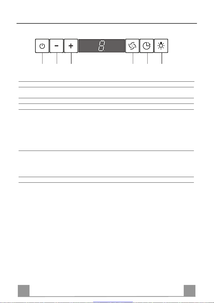
TASTO FUNZIONI
T
1 ON/OFF Motore Attiva e arresta il motore d’aspirazione. Sul display viene
T
2 Velocità - Decrementa la velocità del motore: V3 →V2 → V1
T3 Velocità + Incrementa la velocità del motore: V1→V2→ V3
T4 Velocità intensiva Attiva la velocità intensiva da qualsiasi velocità o da motore
5 Delay Attiva e disattiva la modalità di arresto totale della cappa
T
L Luci Accende e spegne le luci della cappa.
3
2
T4T
5
L
Quadro Comandi
visualizzato lo step di velocità precedentemente impostat a.
spento.Per disinserirl a basta premere di nuovo lo stesso tasto
o spegnere il motore. L’intensiva non è attivabile se è attiva
la funzione Delay. La velocit à intensiva è tempor izzata a 10
minuti: sul display viene visualizzato H e il punto in basso a
destra lampeggia una volta al secondo. Al termine dei 10 minuti il sistema torna auto maticamente al la velocità pr ecedentemente impostata.
(motore+luci) dopo 30 minuti: il display visualizza la velocità del motore e il punto in basso a destra lampeggia una
volta al secondo. Per disabilitare il Delay si può ripremere lo
stesso tasto oppure spegnere il motore
Great user manuals database on UserManuals.info
Page 13
IT 113
MANUTENZIONE
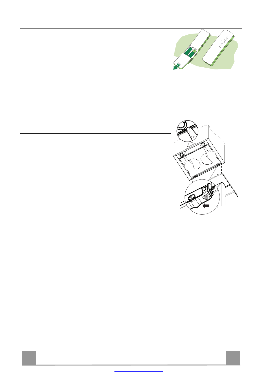
TELECOMANDO (OPZIONALE)
Questo apparecchio può essere c omandato per mezzo di un tel ecomando, alimentato con pile alcaline zinco-carbone da 1,5 V del
tipo standard LR03-AAA.
• Non riporre il telecomando in prossimità di fonti di calore.
• Non disperdere le pile nell’ambiente, depositarle negli appositi
contenitori.
Pulizia dei Confort Panel
• Aprire il Confort Panel tirandolo.
• Sganciare il pannello dal corpo cappa facendo scorrere
l’apposita leva del perno di fissaggio.
• Il confort panel non va assolutamente lavato in lavastoviglie.
• Pulirlo esternamente con un panno umido e detersivo liquido
neutro.
• Pulirlo anche intern amente utilizzando un panno umido e detergente neutro; non utilizzare panni o spugne bagnate, né getti
d’acqua; non utilizzare sost anze abrasive.
• Ad operazione ultimata riagganciare il pannello al corpo cappa
e richiuderlo.
.
Great user manuals database on UserManuals.info
Page 14
IT 114
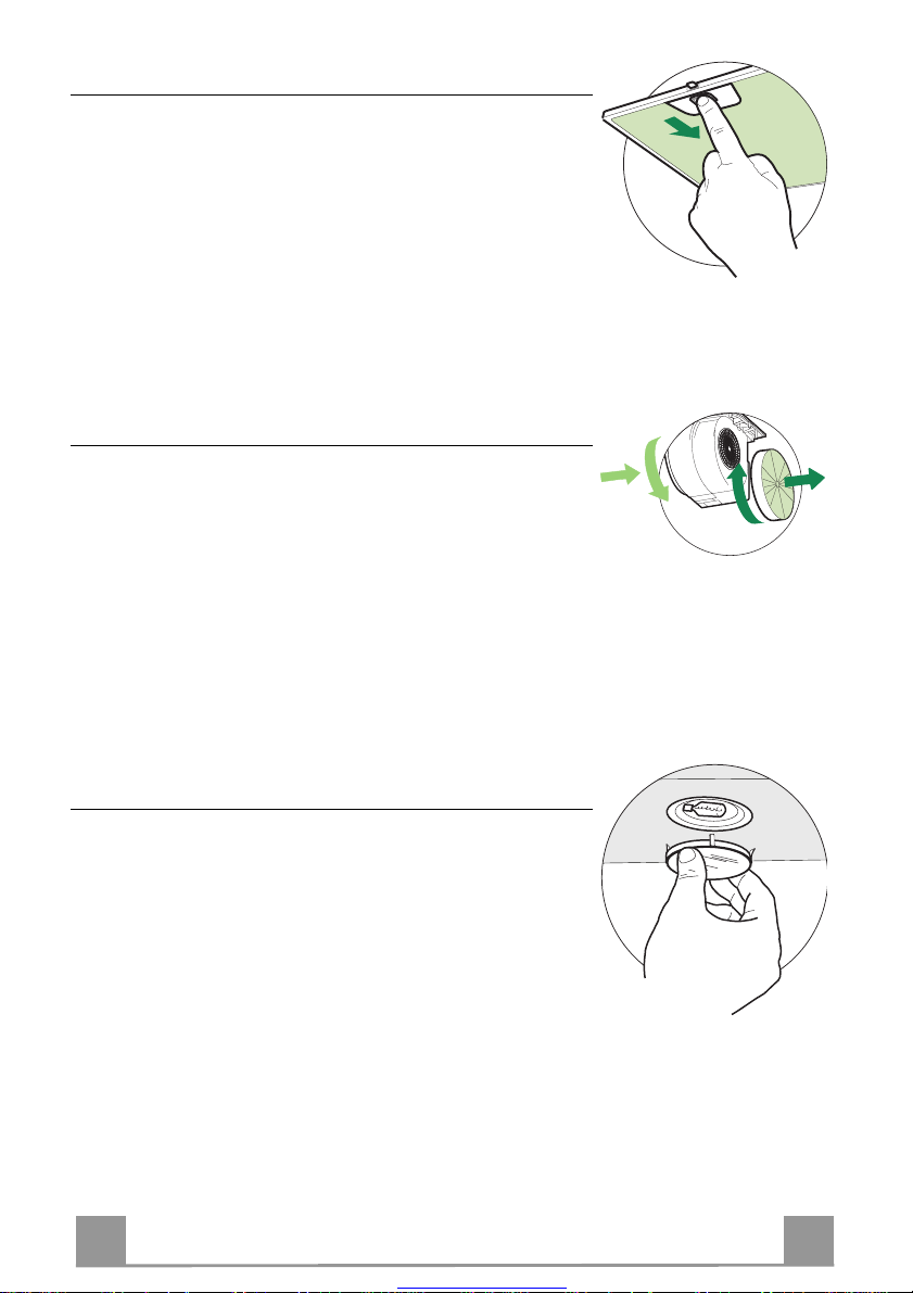
Filtri antigrasso
A
B
PULIZIA FILTRI ANTI GR A SSO META L L ICI AUTO PO RTAN TI
• Sono lavabili anche in lavastoviglie, e necessitano di essere
lavati ogni 2 mesi circa di utilizzo o più frequentemente, per un
uso particolarmente intenso.
• Togliere i Filtri uno alla volta, spingendoli verso la parte posteriore del gruppo e tir ando contemporaneamente verso il basso.
• Lavare i Filtri evitando di piegarli, e lasciarli asciugare prima
di rimontarli.
• Rimontarli facendo attenzione a mantenere la maniglia verso la
parte visibile esterna
Filtri antiodore al Carbone attivo (Versione Filtrante)
Il Filtro antiodore al Carbone attivo non è lavabile e non è rigenerabile, va sostituito ogni 4 mesi circa di utilizzo o più frequentemente, per un uso particolarmente intenso.
SOSTITUZIONE
• Togliere i Filtri antigrasso.
• Rimuovere i Filtri antiodore al Carbone attivo saturi, come indicato (A).
• Montare i nuovi Filtri, come indicato (B).
• Rimontare i Filtri antigrasso.
Illuminazione
SOSTITUZIONE LAMPADE
Lampade alogene da 20 W
• Togliere il bloccavetro metallico a pression e facendo leva sotto
la ghiera, sostenendolo con una mano.
• Estrarre la l ampad ina alogena dal portalampada.
• Sostituirla con una nuova lampadina di uguali caratteristiche,
facendo attenzione ad inserire correttamente i due spinotti nella
sede del portalampade.
• Rimontare il bloccavetro a pressione.
Great user manuals database on UserManuals.info
Page 15
EN 115
RECOMMENDATIONS AND SUGGESTIONS
650 mm min.
INSTALLATION
• The manufacturer will not be held liable for any damages resulting
from incorrect or improper installation.
• The minimum safety distance between the cooker top and the ex tractor hood is 650 mm.
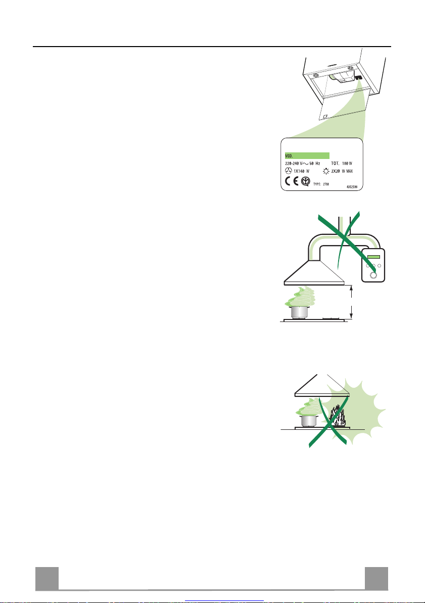
• Check that the mains voltage corresponds to that indicated on the
rating plate fixed to the inside of the hood.
• For Class I applianc es, c heck t hat th e domes tic po wer suppl y gua ran tees adequate earthing.
Connect t he extractor to the exhaus t flue through a pipe of minimum
diameter 120 mm. The route of the flue must be as short as possible.
• Do not connect the extractor hood to exhaust ducts carry ing combustion fumes (boilers, fireplaces, etc.).
• If the extractor is used in conjuncti on with non-electrical appliances
(e.g. gas burning appliances), a suffici ent degree of aeration must be
guaranteed in the room in order to prevent the backflow of exhaust
gas. The kitchen must have an opening communicating directl y with
the open air in order to guarantee the entry of clean air.
USE
• The extractor hood has been designe d ex cl us iv ely for domesti c us e to
eliminate kitchen smells.
• Nev er use the hood for p urposes other than fo r which it has ben designed.
• Never leave high naked flames under the hood when it is in operation.
• Adj ust the flame intensity to direct it onto the bottom of the pan only,
making sure that it does not engulf the sides.
• Deep fat fryers must be continuously monitored during use: overheated oil can burst into flames.
• The hood should not be us ed by chil dren or persons not inst ructed in
its correct use.
MAINTENANCE
• Switch off or unplug the appliance from the mains supply before carrying out any maintenance work.
• Clean and/or replace the Filters after the specified time period.
• Clean the hood using a damp cloth and a neutral liquid detergent.
Great user manuals database on UserManuals.info
Page 16

EN 116
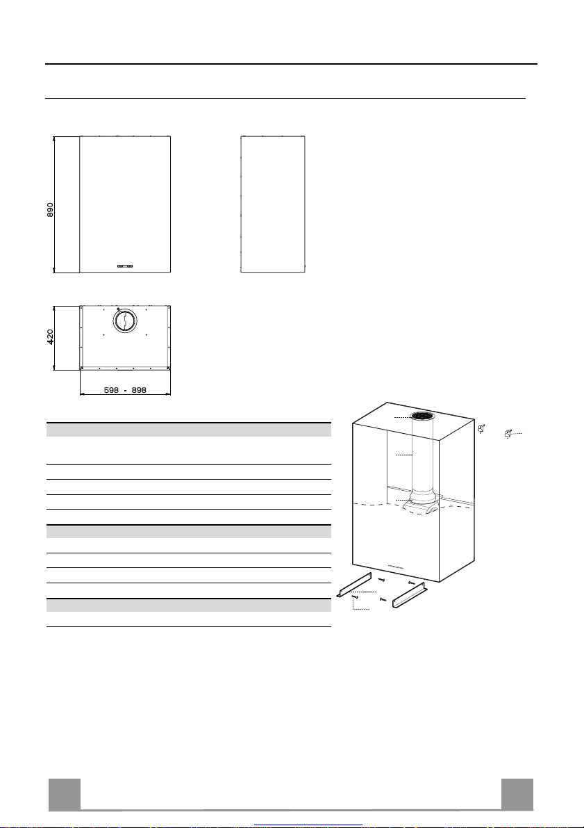
CHARACTERISTICS
Dimensions
Components
Ref. Q.ty Product components
1 1 Hood Body complete with: Controls, Light, Suction Unit,
7 1 PVC Pipe (fit ted)
8 1 Inclinable grid ø125 (fitted)
9 1 Reduction flange ø 150-120 mm (fitted)
Ref. Q.ty Assembly components
7.5 2 Glass Support Corners
11a 2 SB 12/1 0 Plugs
12c 4 Screws 2,9 x 6,5
Q.ty Documents
1 Instruction Manual
Filters, Lower Duct
8
11a
7
9
7.5
12c
Great user manuals database on UserManuals.info
Page 17

EN 117
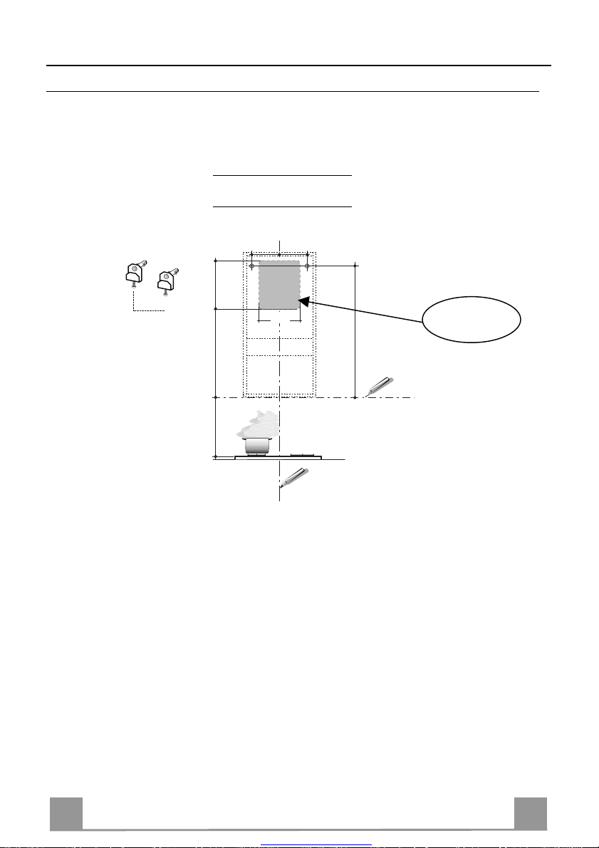
INSTALLATION
Boring the wall
If you want to use the hood in suction version with the air outlet at the back o f the hood, make
sure to follow the indications given below in the drawing for a correct boring operation of the air
outlet opening.
Tipo Cappa 45 60
X 180 240
X
X
11a
540 300
250
808
Rear air outlet
zone
650 mm min
On the wall, trace:
• a vertical line up to the ceilin g or top limit, at the centr e of the area where you intend to fit
the hood;
• a horizontal line at: 650 mm min. above the cooking hob;
• As shown, mark a reference point at 808 mm above the horizontal reference line, and at X
mm (X= see table in figure) to the right of the vertical reference line.
• Repeat this operation on the opposite side, checking levelling.
• Drill the points marked using a ø 12 mm bit
• Insert plugs with screws and brackets 11a in the holes then tighten them.
Great user manuals database on UserManuals.info
Page 18

EN 118
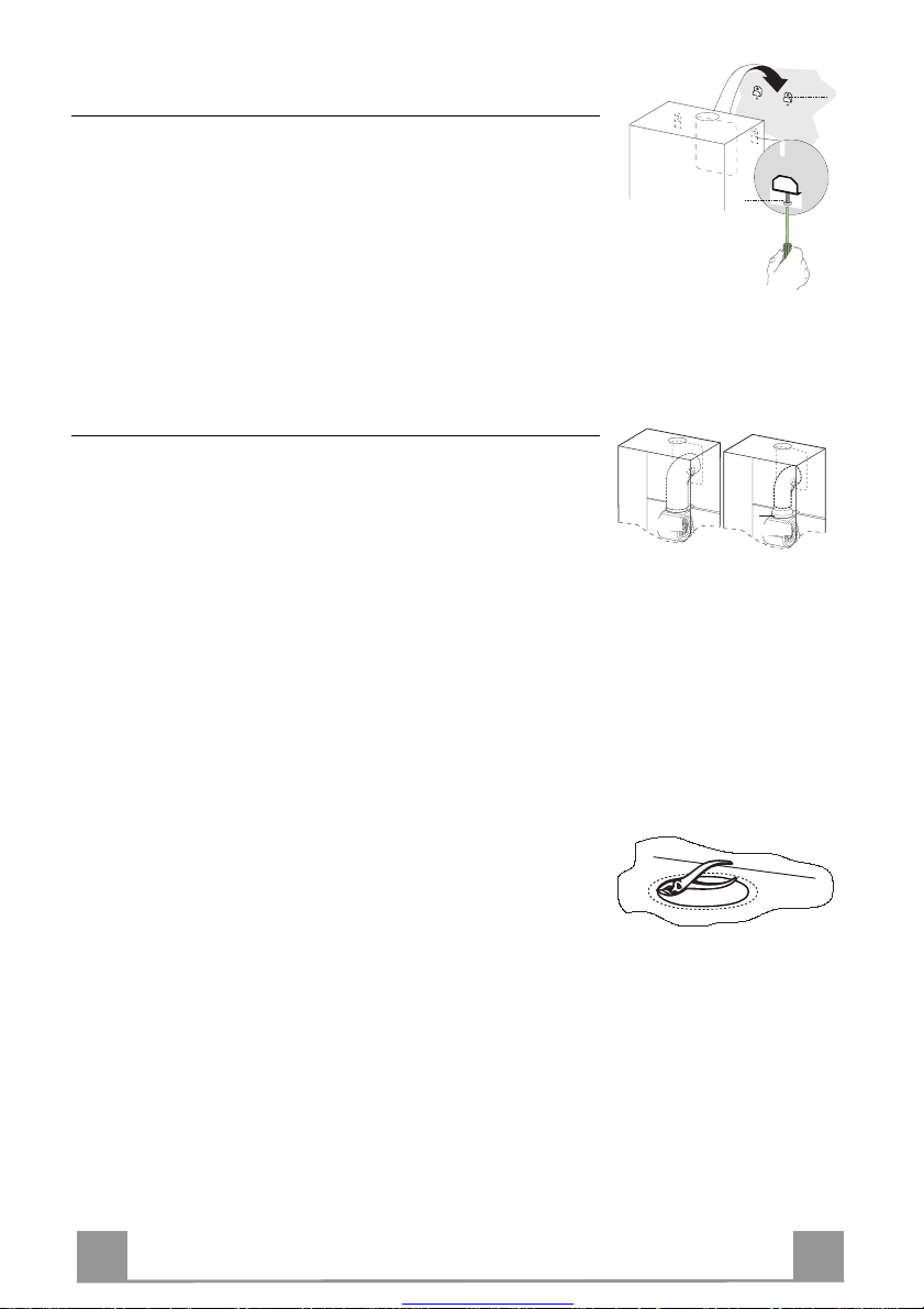
Hood body assembly
Vr
11a
9
ø 120
ø 150
• Adjust the two screws Vr of brackets 11a, by just placing them
in position.
• Hook the hood body to the two brackets 11a.
• Pull the Comfort Panel to open it, remove the filters one by
one, push them towards the rear part of the unit and pull
downwards at the same time .
• From inside the hood body, tighten the screws Vr to level the
body.
Connections
AIR OUTLET IN SUCTION VERSION
To fit the hood in suction version, connect the hood to the outlet
by means of a 150 o 120 mm ø rigid or flexible pipe, the choice
of which is left to the technician. The pipe can be fitted either at
the top or at the back of the hood.
Before proceeding with t he connections, and in case they have
not been removed yet, remove the inclinable grid 8 and pvc pipe
7. The reduction flange 9 should only be removed to carry out
150 ø connections.
REAR OUTLET
• Please b ear in mind that the exhaust opening must be carried
out following the drawing indicated in the wall boring paragraph.
• Break the rear outlet using pliers.
• When using a 120 mm ø pipe, insert the reduction flange 9 in
the hood body outlet.
• Keep the pipe in position using clamps. The necessary material
is not supplied.
• Remove any charcoal anti-odour filters, if used.
TOP OUTLET
• Remove the inclinable grid 8.
• When using a 150 mm ø pipe, break the top air outlet along
• When using a 120 mm ø pipe, insert the reduction flange 9 in
• Keep the pipe in position using clamps. The necessary material
• Remove any charcoal anti-odour filters, if used.
the pre-cut line with pliers.
the hood body outlet.
is not supplied.
Great user manuals database on UserManuals.info
Page 19

EN 119
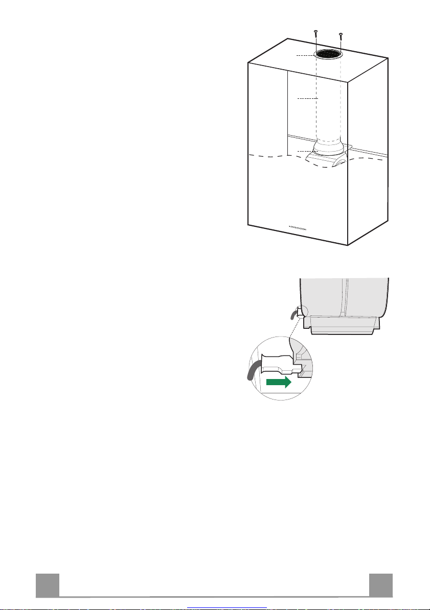
AIR OUTLET IN RECIRCULATING VERSION
• Re-position any components already fitted for recirculating version that have been removed.
• Re-position reduction flange 9 onto the hood body.
• Re-position pvc pipe 7 onto the flange.
• Re-tighten the inclinable grid 8 onto the air outlet,
making sure it is positioned well on the pipe.
• Make sure the charcoal anti-odour filters are in place.
ELECTRICAL CONNECTION
• Connect the hood to the mains through a two-pole
switch having a contact gap of at least 3 mm.
• Remove the grease filters (see paragraph Maintenance) being sure that the connector of the feeding
cable is correctly inserted in the socket p laced on t he
side of the fan.
8
7
9
Great user manuals database on UserManuals.info
Page 20

EN 220
USE
T
T
1
T
TOUCH CONTROL FUNCTION
T1 ON/OFF Motor Switches the hood motor on and off. The latest selected
T2 Speed - Decreases the suction speed: V3 → V2 → V1
T3 Speed + Increases the suction speed: V1 → V2 → V3
T4 Intensi ve speed Activates the intensive sp eed from any previously selected
T5 Delay Activates and deactivates the delayed shutdown of the hood
L Lighting Turns light on and off.
3
2
T4T
5
L
Control panel
speed appears on the displ ay.
speed. The intensive sp eed can be activated even when the
motor is OFF. By pressing the same touch control once again
or by switching off the motor this function can be deactivated. Intensive speed cannot be activated when the delay
function is on. Intensive speed has been timed at 10 minutes:
H appears on the display and a spot down on the right side
flashes once a second. After 10 minutes the system activates
automatically the latest select ed speed.
(motor + lighting) at 30 minutes: the selected speed o f the
hood appears on the display and a spot down on the right
side flashes once a second. By pressing the same touch control once again or by switching off the motor delay function
can be deactivated.
Great user manuals database on UserManuals.info
Page 21

EN 221
MAINTENANCE
REMOTE CONTROL (OPTIONAL)
The appliance can be controlled using a remote control powered
by a 1.5 V carbon-zinc alkaline batteries of the standard LR03AAA type.
• Do not pl ace the remote control near to heat sources.
• Used batteries must be disposed of in the proper manner.
Cleaning the Comfort Panels
• Pull the Comfort Panel to open it.
• Disconnect the panel from the hood canopy by sliding the fixing pin lever.
• The comfort panel must never be washed in a dishwasher.
• Clean the outside using a damp cloth and neutral liquid detergent.
• Clean the inside as well using a damp cloth and neutral detergent; do not use wet cloths or sponges, or jets of water; do not
use abrasive substances.
• When the above operation has been comp leted, hook the panel
back to the hood canopy and close it by turning the knob in the
opposite direction.
Great user manuals database on UserManuals.info
Page 22

EN 222
Grease filters
A
B
CLEANING META L SELF- SUPPO RTING GREASE FILTERS
• The filters must be cleaned every 2 months of operation, or
more frequently for particularly heavy usage, and can be
washed in a dishwasher.
• Remove the filters one at a time by pushing them towards
the back of the group and pulling down at the same time.
• Wash the filters, taking care not to bend them. Allow them
to dry before refitting.
• When refitting the filters, make sure that the handle is visible
on the outside.
Activated charcoal filter (Recirculation version)
These filters are not washable and cannot be regenerated, and
must be replaced approximatel y every 4 months of operati on, or
more frequently with heavy usage.
REPLACING THE ACTIVATED CHARCOAL FILTE R
• Remove the metal grease filters
• Remove the saturated activated charcoal filter as shown (A).
• Fit the new filters (B).
• Replace the metal grease filters.
Lighting
LIGHT REPLACEMENT
20 W halogen light.
• Remove the snap-on lamp cover by levering it from under the
metal ring, supporting it with one hand.
• Remove the halogen lamp from the lamp holder by pulling
gently.
• Replace the lamp with a new one of the same type, making
sure that you insert the two pins properly into the housings on
the lamp holder.
• Replace the snap-on lamp cover.
Great user manuals database on UserManuals.info
Page 23

FR 223
CONSEILS ET SUGGESTIONS
650 mm min.
INSTALLATION
• Le fabricant décline toute responsabilité en cas de dommage dû à
une installation non correcte ou non conforme aux règles de l’art.
• La di stance minimale de sécurité entre le plan de cuisson et l a hotte
doit être de 650 mm au moins.
• Vérifier que la tensi on du s ecteu r c or respond à l a val eur qui figu re s ur
la plaquette apposée à l’intérieur de la hotte.
• Pour les Appareils appartenant à la Ière Classe, veiller à ce que la
mise à la terre de l’installation électrique domestique ait été effectuée
conformément aux normes en vigueur.
• Connecter la hotte à la sortie d’air aspiré à l’aide d’une tuyauterie
d’un diamètre égal ou supérieur à 120 mm. Le parcours de la
tuyauterie doit être le plus court possible.
• Eviter de connecter la hotte à des conduites d’évacuation de fumées
issues d’une combustion tel que (Chaudière, cheminée, etc…).
• Si vous utilisez des appareils qui ne fonctionnent pas à l’électricité
dans la pièce ou est installée la hotte (par exemple: des appareils
fonctionnant au gaz), vous devez prévoi r une aération suffisante du
milieu. Si la cuisine en est dépou rvue, pratiquez une ouverture qui
communique avec l’extérieur pour garantir l’infiltration de l’air pur.
UTILISATION
• La hotte a é té conçue exclusivement pour l’usage domestique, dans
le but d’éliminer les odeurs de la cuisine.
• Ne jamais utiliser abusivement la hotte.
• Ne pas lai sser les flammes libres à forte intensité quand la hotte es t
en service.
• Toujours régler les flammes de manière à éviter toute sortie latérale
de ces dernières par rapport au fond des marmites.
• Contrôler les friteuses lors de l’utilisation car l’huile surchauffée
pourrait s’enflammer.
• La hotte ne doit pas être utilisée p ar des enfants ou des personnes ne
pouvant pas assurer une utilisation correcte.
ENTRETIEN
• Avant de procéder à toute opération d’entretien, retirer la hotte en
retirant la fiche ou en actionnant l’interrupteur général.
• Effectuer un entretien scrupuleux et en temps dû des F iltres, à la cadence conseillée.
• Pour le nettoyage des surfaces de la hotte, il suffit d’utiliser un chiffon
humide et détersif liquide neutre.
Great user manuals database on UserManuals.info
Page 24

FR 224
CARACTERISTIQUES
Encombrement
Composants
Réf. Q.té Composants du Produit
1 1 Corps de la Hotte comprenant: Commandes, Éclairage,
7 1 Tuyau en PVC (Installé)
8 1 Grille orientable ø125 (Installée)
9 1 Flasque de Raccord ø 150-1 20 mm (Ins t al lée)
Réf. Q.té Composants d’Installation
7.5 2 Cornières de Support Verre
11a 2 Chevilles SB 12/10
12c 4 Vis 2,9 x 6,5
Q.té Documentation
1 Manuel d’Instructions
Groupe Ventil ateur, Filtres, Cheminée I nférieure.
8
11a
7
9
7.5
12c
Great user manuals database on UserManuals.info
Page 25

FR 225
INSTALLATION
Perçage de la Paroi
Si on souhaite connecter la hotte dan s la version asp irante, en faisan t sortir le tuyau sur la partie
arrière, il ne faut pas oublier que le trou d’évacuation d e l’air doit être réalisé en suivan t les indications reportées ci-après dans le dessin.
Type de Hotte 45 60
X 180 240
X
X
11a
540 300
250
808
Zone arrière éva-
cuation air
650 mm min
Marquer sur la Paroi:
• une ligne Verticale jusqu’au plafond ou à la limite supérieure, au milieu de la zone prévue
pour le montage de la Hotte;
• une ligne Horizontale à: 650 mm min. sur les Plaques de Cuisson;
• Marquer comme indiqué un point de référence à 808 mm sur la ligne horizontale de référence et à X mm (X = voir tableau dans l’illustration) à droite de la ligne verticale de référence.
• Répéter cette opération sur le côté opposé, en vérifiant le nivellement de celui-ci.
• Percer ø 12 mm les points marqués.
• Insérer les chevilles avec vis et bride 11a dans les trous, puis visser.
Great user manuals database on UserManuals.info
Page 26

FR 226
Montage du Corps de la Hotte
Vr
11a
9
ø 120
ø 150
• Régler les deux vis Vr, des brides 11a, sans les visser à fond.
• Accrocher le corps de la hotte aux 2 brides 11a.
• Ouvrir le Confort Pannel en le tirant, retirer les Filtres, l’un
après l’autre, en les poussant vers la p artie arrière du groupe et
en tirant simultanément vers le bas.
• Depuis l’intérieur du corps de la hotte, intervenir sur les Vis Vr
pour effectuer le nivellement du Corps de la Hotte.
Connexions
SORTIE D’ÉVACUATION DE L’AIR VERSION ASPIRANTE
Pour l’installation dans la Version Aspirante, connecter la Hotte à
la conduite d’évacuation au moyen d’un tuyau rigide ou flexible
de ø 150 ou 120 mm., dont le choix pourra être effectué par
l’installateur. Le tuyau peut sortir aussi bien de la paroi supérieure que de celle arrière de la hotte.
Avant d’effectuer les connexions d’aspiration, retirer – si cela n’a
pas encore été fait – la grille orientable 8 et le tuyau en PVC 7.
La flasque de raccord 9 doit être retirée uniquement pour effectuer les connexions de ø 150.
SORTIE D’ÉVACUATION ARRIÈRE
• Nous rappelons que, pour réaliser le trou d’évacuation, il faut
suivre le schéma reporté dans le paragraphe relatif au perçage
de la paroi.
• Ouvrir l e trou d’évacuation arrière à l’aide d’ une pince.
• Pour la connexion avec un tuyau ø120 mm,, insérer la Flasque
de raccord 9 sur la Sortie du Corps de la Hotte.
• Fixer le tuyau à l’aide de colliers serre-tube appropriés. Le matériau nécessaire n’est par four ni avec l’appareil.
• Retirer les éventuels Filtres Anti-odeur au Charbon actif.
SORTIE D’ÉVACUATION SUPÉRIEURE
• Retirer la grille orientable 8.
• Pour la connexion avec un tuyau ø 150 mm, ouvrir le trou
• Pour la connexion avec un tuyau ø120 mm,, insérer la Flasque
• Fixer le tuyau à l’aide de colliers serre-tube appropriés. Le ma-
• Retirer les éventuels Filtres Anti-odeur au Charbon actif.
d’évacuation de l’air supérieur, le long de la ligne hachurée à
l’aide d’une pince.
de raccord 9 sur la Sortie du Corps de la Hotte.
tériau nécessaire n’est par four ni avec l’appareil.
Great user manuals database on UserManuals.info
Page 27

FR 227
SORTIE D’ÉVACUATION DE L’AIR VERSION FILTRANTE
• Remettre en place les composants pour la version
filtrante déjà installés, s’ils ont été retirés.
• Réintroduire la Flasque de raccord 9 sur la sortie du
Corps de la Hotte.
• Réinsérer le tuyau en PVC 7 sur la Flasque.
• Revisser la Grille orientable 8 sur la sortie
d’évacuation de l’air, en veillant à ce qu’elle soit positionnée correctement sur le tuyau.
• S’assurer que les Filtres anti-odeur au Charbon actif
soient présents.
BRANCHEMENT ELECTRIQUE
• Brancher la hotte sur le secteur en in terposant un interrupteur bipolaire avec ou verture des contacts d’au
moins 3 mm.
• Enlever les filtres à graisse (voir § "Entretien") et
s'assurer que le connecteu r du câble d'alimentation
soit bien branché dans la prise du diffuseur.
8
7
9
Great user manuals database on UserManuals.info
Page 28

FR 228
UTILISATION
T
T
1
T
TOUCHE FONCTIONS
T1 ON/OFF Moteur Actionne et arrête le moteur d’aspiration. Sur l’afficheur est
T2 Vitesse - Réduit la vitesse du moteur: V3 → V2 → V1
T3 Vitesse + Augmente la vitesse du moteur: V1 → V2 → V3
T4 Vitesse intensive Actionne la vitesse intensive en partant d’une vitesse quel-
T5 Delay Actionne et désactive la modalité d’arrêt total de la hotte
L Éclairage Allume et éteint l’éclairage de la hotte.
3
2
T4T
5
L
Tableau des commandes
visualisé le pas de la vitesse précédemment sélectionnée.
conque ou lorsque le moteur est éteint. Pour la désactiver, il
suffit d’appuyer à nouveau sur la même touche qui a été utilisée ou d’éteindre le moteur. La vitesse intensive ne peut pas
être actionnée si la fonction Delay est active. La vitesse intensive est temporisée sur 1 0 minutes: sur l ’afficheur est visualisée l’inscription H et le point en bas à droite clignote
une fois par seconde. Lorsque 10 minutes se sont écoulées, le
système retourne automatiquement à la vitesse précédemment sélectionnée.
(moteur+éclairage) après 30 minutes: l’afficheur visual ise la
vitesse du moteur et le point en bas à droite clignote une fois
par seconde. Pour invalider la fonction Delay on peut appuyer à nouveau sur la même touche ou éteindre le moteur.
Great user manuals database on UserManuals.info
Page 29

FR 229
ENTRETIEN
TELECOMMANDE (FOURNIE SUR DEMANDE)
Il est possible de commander cet appareil au moyen d’une télécommande, alimentée avec des piles alcalines zinc-charbon 1,5 V
du type standard LR03-AAA.
• Ne pas ranger la télécommande à proximité de sources de chaleur.
• Ne pas jeter les piles; il faut les déposer dans les récipients de
récolte spécialement prévus à cet effet.
Nettoyage des Confort Panel
• Ouvrir le Confort Panel, en tirant ce dernier.
• Décrocher le panneau du corps de la hotte, en faisant coulisser
le levier du goujon de fixation spécialement prévu.
• En aucun cas, le confort panel ne doit être lavé au lavevaisselle.
• Le nettoyer à l’extérieur à l’aide d’un chiffon humide et d’un
détergent liquide neutre.
• Le nettoyer également à l’intérieur, en utilisant un chiffon humide et un détergent neutre; ne pas utiliser des chiffons ou des
éponges mouillées, ni des jets d’eau; ne pas utiliser des substances abrasives.
• Lorsque l‘o pération est achevée, accrocher à nouveau le panneau sur le corps de la hotte, puis le refermer, en tournant le
bouton dans le sens inverse par rapport à l’ouverture.
Great user manuals database on UserManuals.info
Page 30

FR 330
Filtres anti-graisse
A
B
NETTOYAGE FILTRES ANTI-GRAISSE METALLIQUES AUTOPORTEURS
• Lavables au lave-vaisselle, ils doivent être lavés environ tous
les 2 mois d’emploi ou plus fréquemment en cas d’emploi particulièrement intense.
• Retirer les filtres l’un aprés l’autre, en les poussant vers la partie arrière du groupe et en tirant simultanément vers le bas.
• Laver les filtres en évitant de les plier et les laisser sécher avant
de les remonter.
• Remonter les filtres en veillant à ce que la poignée reste vers la
partie visible externe
Filtre anti-odeur (Version filtrante)
Il ne sont pas lavables ni régénérables, il faut les remplacer au
moins tous les 4 mois d’emploi ou plus fréquemment en cas
d’emploi particulièrement intense.
REMPLACEMENT FILTRE AU CHARBON ACTIF
• Retirer les filtres anti-graisse métalliques.
• Retirer les filtres anti-odeur au charbon actif saturés, comme
indiqué (A).
• Monter les nouveaux filtres (B).
• Remonter le filtres anti-graisse métalliques.
Eclairage
REMPLACEMENT LAMPES
Lampe halogène de 20 W.
• Enlever le dispositif métallique de blocage du verre par encliquetage en exerçant une pression sous l’embout en le soutenant
d’une main.
• Extraire la lampe du support
• Remplacer la lampe par une no uvelle ayant le mêmes car actéristiques, en prenant soi n d'in sérer correcte ment les d eux fiches
dans le support.
• Remonter le dispositif de blocage du verre par encliquetage.
Great user manuals database on UserManuals.info
Page 31

DE 331
EMPFEHLUNGEN UND HINWEISE
650 mm min.
MONTAGE
• Der Herstell er haftet nicht für Schäden, die auf ein e fehlerhafte und
unsachgemäße Montage zurückzuführen sind.
• Der minimale Sicherheitsabstand zwischen Kochmulde und Haube
muss 650 mm betragen.
• Prüfen, ob die Netzspannung mit dem Wert au f dem im Haubeninneren angebrachten Schild übereinstimmt.
• Bei Geräten der Klasse I ist sic herzustellen, dass die elektri sche Anlage des Wohnhauses über eine vorschriftsmäßige Erdung verfügt.
• Das Anschlussrohr der Haube zur Luftaustrittsöffnung muss einen
Durchmesser von 120 mm oder darüber aufweisen. Der Rohrverl auf
muss so kurz wie möglich sein.
• Die Haube darf an keine Entlüftungs schächte anges chloss en werden,
in die Verbrennungsgase (Heizkessel, Kamine usw.) geleitet werden.
• Werden im Raum außer der Dunsta bzugshaube andere, nicht elektrisch betriebene (z.B. gasbetri ebene) Geräte verwendet, muss für eine ausreichende Belüftung gesorgt werden. Sollte die Küche diesbezüglich nicht entsprechen, ist an ein er Aussenwand eine Öffn ung anzubringen, die Frischluftzufuhr gewährleistet.
BEDIENUNG
• Die Dunstabzugshaube ist ausschließlich zum Einsatz im privaten
Haushalt und zur Beseitigung von Küchengerüchen vorgesehen.
• Unsachgemäßer Einsatz der Haube ist zu unterlassen.
• Große Flammen bei eingeschalteter Haube niemals unbedeckt lassen.
• Die Intensivität der Flamme i st so zu reguliere n, dass s ie den Topfboden nicht überragt.
• Frittiergeräte müssen während des Gebrauchs stets beaufsichtigt
werden: überhitztes Öl kann sich entzünden.
• Die Dunstabzugshaube da rf vo n Kin dern ode r Personen, die hi nsichtlich der Bedienung nicht unterwi esen wurden, keinesfalls verwendet
werden.
WARTUNG
• Bev or Wartungsarbeiten du rchgeführt werden, muss die Stromzufuh r
zur Haube unterbrochen werden, indem der Stecker gezogen oder
der Hauptschalter abgeschaltet wird.
• Bei der Filterwartung müssen die vom Herstell er empfohlenen Zeiträume zum Austauschen der Filter genauestens eingehalten werden.
• Zur Reinigung der Haubenfl ächen Wir empfehlen ein feuchtes Tuch
und ein mildes Flüssigreinigungsmittel.
Great user manuals database on UserManuals.info
Page 32

DE 332
CHARAKTERISTIKEN
Platzbedarf
Komponenten
Bez. Menge Produktkomponenten
1 1 Haubenkörper komplett mit: Steuerungen, Beleuch-
7 1 PVC-Rohr (installiert)
8 1 Luftstromrichtungsgitter ø 125 (installiert)
9 1 Reduktionsflansch ø 150-120 mm (installiert)
Bez. Menge Installationskomponenten
7.5 2 Glasträgerwinkel
11a 2 Dübel SB 12/10
12c 4 Schrauben 2,9 x 6,5
Menge Dokumentation
1 Betriebsanleitung
tung, Ventilatorgruppe, Filter, unterem Kamin
8
11a
7
9
7.5
12c
Great user manuals database on UserManuals.info
Page 33

DE 333
MONTAGE
Bohren der Wand
Soll die Haube in Abluftversion angeschlossen werden, indem das Rohr an der Rückseite ausgeleitet wird, so muss die Abzugsöffnung gemäß den Angaben in der folgenden Zeichnung ausgeführt werden.
Haubentyp 45 60
X 180 240
X
X
11a
540 300
250
808
Bereich Luftau-
stritt hinten
650 mm min
An der Wand anzeichnen:
• eine senkrechte Linie bis zur Decke oder zum oberen Rand in der Mitte des Installationsbereichs der Haube,
• eine horizontale Linie mindestens 650 mm oberhalb der Kochmulde.
• Wie angegeben 808 mm oberhalb der waagrechten Bezugslinie und X mm (X = siehe Tabelle in der Zeichnung) rechts von der senkrechten Bezugslinie einen Punkt kennzeichnen.
• Diesen Vorgang an der gegenüberliegenden Seite wiederholen und die Ausrichtung überprüfen.
• Die gekennzeichneten Punkte mit einem Bohrer ø 12 mm bohren.
• Die Dübel mit Schraube und Bügel 11a in die Bohrungen einfügen und festschrauben.
Great user manuals database on UserManuals.info
Page 34

DE 334
Montage des Haubenkörpers
Vr
11a
9
ø 120
ø 150
• Die beiden Schrauben Vr der Bügel 11a so regulieren, dass sie
nur bis zum Gewindebeginn eingeschraubt sind.
• Den Haubenkörper bei den 2 Bügeln 11a einhaken.
• Das Comfort Panel durch Herausziehen öffnen. Die Filter einzeln entnehmen, indem sie zur Rückseite der Gruppe geschoben und gleichzeitig nach unten gezogen werden.
• Vom Haubeninneren her den Haubenkörper mit Hilfe der
Schrauben Vr ausrichten.
Anschlüsse
LUFTAUSTRITT BEI ABSAUGVERSION
Für die Installation als Abluftversion die Haube mit Hilfe eines
starren oder flexiblen Rohrs mit ø 150 oder 120, dessen Wahl
dem Installateur obliegt, an die Auslassleitung anschließen. Das
Rohr kann an der Oberseite oder an der Rückseite der Haube austreten.
Bevor die Absauganschlüsse durchgeführt werden, das Luftstromrichtungsgitter 8 und das PVC-Rohr 7 entfernen, falls nicht
schon geschehen. Der Reduktionsflansch 9 ist nur für die Durchführung von Anschlüssen ø 150 zu entfernen.
RÜCKSEITIGER LUFTAUSTRITT
• Die Abzugsöffnung wird gemäß dem Schema erstellt, das im
Absatz über die Wandbohrung angeführt ist.
• Die hintere Abzugsöffnung mit Hilfe einer Zange ausbrechen.
• Für den Anschluss an ein Rohr ø 120 mm den Reduktionsflansch 9 in den Austritt aus dem Haubenkörper einsetzen.
• Das Rohr mit passenden Rohrschellen fixieren. Das erforderliche Material ist nicht im Lieferumfang enthalten.
• Eventuelle Aktivkohlefilter ausbauen.
OBERER LUFTAUSTRITT
• Das Luftstromrichtungsgitter 8 entfernen.
• Für den Anschluss an ein Rohr ø 150 mm die obere Abzugs-
• Für den Anschluss an ein Rohr ø 120 mm den Reduktions-
• Das Rohr mit passenden Rohrschellen fixieren. Das erforderli-
• Eventuelle Aktivkohlefilter ausbauen.
öffnung mit Hilfe einer Zange entlang der Markierung ausbrechen.
flansch 9 in den Austritt aus dem Haubenkörper einsetzen.
che Material ist nicht im Lieferumfang enthalten.
Great user manuals database on UserManuals.info
Page 35

DE 335
LUFTAUSTRITT BEI UMLUFTVERSION
• Sollten die bereits eingebauten Komponenten für die
Umluftversion entfernt worden sein, diese wieder
einsetzen.
• Den Reduktionsflansch 9 wieder auf den Luftaustritt
des Haubenkörpers aufsetzen.
• Das PVC-Rohr 7 wieder au f den Flansch aufsetzen.
• Das Luftstromrichtungsgitter 8 wieder auf den Luft-
austritt aufschrauben. Dabei darauf achten, dass es
korrekt auf dem Rohr sitzt.
• Darauf achten, dass Aktivkohle-Geruchsfilter vorhanden sind.
ELEKTROANSCHLUSS
• Bei Anschluss der Haube an das Stromnetz muss ein
zweipoliger Schalter mit einem Öffnungsweg von
mindestens 3 mm zwischengeschaltet werden.
• Entfernen Sie die Fettfilter (s. Abschnitt „Wartung“)
und versichern Sie sich, daß die Kabelverbindung in
die Steckdose des Gebläses einwandfrei eingesteckt
wird.
8
7
9
Great user manuals database on UserManuals.info
Page 36

DE 336
BEDIENUNG
T
T
1
T
TASTE FUNKTIONEN
T1 Motor ON/OFF Schaltet den Gebläsemotor ein und aus. Auf dem Display wird die
T2 Geschwindigkeit - Erhöht die Geschwindigkeit des Motors: V3 → V2 → V1
T3 Geschwindigkeit + Verringert die Geschwindigkeit des Motors: V1 → V2 → V3
T4 Intensivstufe Aktiviert die Intensivstufe von jeder Geschwindigkeitsstufe aus
T5 Delay Aktiviert und deaktiviert den Modus Komplettes Ausschal-
L Beleuchtung Schaltet die Beleuchtung der Haube ein und aus.
3
2
T4T
5
L
Bedienfeld
zuvor eingestellte Geschwindigkeitsstufe angezeigt.
oder bei ausgeschaltetem Motor. Zum Ausschalten einfach die selbe Taste erneut drücken oder den Motor ausschalten. Bei aktivierter Delay-Funktion lässt sich die Intensivstufe nicht aktivieren. Die
Intensivstufe dauert 10 Minuten: Auf dem Display wird H angezeigt und der Punkt unten rechts blinkt einmal pro Sekunde. Nach
10 Minuten kehrt das Syste m automatisch in die zuvor eingestellte
Geschwindigkeitsstufe zurück.
ten der Haube (Motor + Beleuchtung) nach 30 Minuten: Auf
dem Display wird die Geschwindigkeitsstufe des Motors
angezeigt und der Punkt unten rechts blinkt einmal pro Sekunde. Zum Dea kti vieren de r Dela y-Fun ktion die selbe Taste erneut drücken oder den Mo t or ausschalten.
Great user manuals database on UserManuals.info
Page 37

DE 337
WARTUNG
FERNBEDIENUNG (OPTION)
Dieses Gerät kann mit einer Fernbedienung gesteuert werden,
welche mit alkalischen Zink-Kohle-Batterien 1,5 V des Standardtyps LR03-AAA versorgt wird.
• Die Fernbedienung nicht in die Nähe von Hitzequellen legen.
• Batterien müssen vorschriftsmäßig entsorgt werden.
Reinigung der Confort Panel
• Den Confort Panel durch Ziehen öffnen.
• Die Platte vom Haubenkörper aushaken, indem der Hebel des
Befestigungsstiftes verschoben wird.
• Die Confort panel darf keinesfalls im Geschirrspüler gewaschen werden.
• Außen mit einem feuchten Lappen und neutralem Flüssigreiniger säubern.
• Innen mit einem feuchten Lappen und neutralem Reinigungsmittel säubern; keine nassen Lappen oder Schwämme oder
Wasserstrahl verwenden; kein Scheuermittel verwenden.
• Am Ende die Platte wieder am Haubenkörper einhaken und
schließen, indem der Drehknopf in die dem Öffnen entgegengesetzte Richtung gedreht wird.
Great user manuals database on UserManuals.info
Page 38

DE 338
Fettfilter
A
B
SELBSTTRAGENDER METALLFETTFILTER REINIGUNG
• Sie müssen nach 2-monatigem Betrieb bzw. bei starkem
Einsatz auch häufiger gereinigt werden, was im Geschirrspüler möglich ist.
• Die Filter nacheinander aushaken, indem sie auf die Rückseite der Gruppe geschoben und gleichzeitig nach unten gezogen werden.
• Die Filter reinigen (darauf achten, sie nicht zu verbiegen)
und vor der Remontage trocknen lassen.
• Bei der Remontage ist darauf zu achten, dass sich der Griff
auf der sichtbaren Außenseite befindet.
Geruchsfilter (Umluftversion)
Sie können weder gewaschen noch wiederverwendet werden und
sind alle 4 Betriebsmonate bzw. bei starkem Einsatz auch häufiger auszutauschen.
AUSTAUSCHEN DER AKTIVKOHLE FIL TE R
• Die Metallfettfilter entnehmen.
• Den gesättigten Aktivkohle-Geruchsfilter wie gezeigt entfernen (A).
• Die neuen Filter wie gezeigt montieren (B).
• Die Metallfettfilter wieder montieren.
Beleuchtung
AUSWECHSELN DER LAMPEN
Halogenlampe 20 W
• Die mittels Eindrücken befestigte Glashalterung aus Metall
durch Anheben der Zwinge entfernen und die Halterung dabei
mit einer Hand stützen.
• Die Lampe aus der Hal t erung nehmen.
• Die Lampe durch eine gleichwertige ersetzen und bei der Remontage darauf achten, daß die beiden Steckerstifte vorschriftsmäßig in die Lampenfassung eingeführt werden.
• Die Glashalterung wieder eindrücken.
Great user manuals database on UserManuals.info
Page 39

TR 339
TAVSIYELER VE ÖNERILER
650 mm min.
MONTAJ
• Yalnιş veya eksik montajdan doğan herhangi bir zararιn s orumluluğu üreticiye ait değildir.
• Davlumbaz ile pişirici cihazιn ocak kιsmι arasιndaki minimum
güvenlik mesafesi 650 mm.dir.
• Besleme voltajιnιn, davlumbaz içerisine yerleştirilen bilgi etiketinde belirtilenle aynι olup olmadιğιnι kontrol edin.
• Sιnιf I elektrikli aletleri için, güç kaynağιnιn yeterli topraklamayι
sağlayιp sağlamadιğιnι kontrol edin. Minimum 120 mm çapιnda
bir boru yoluyla davlumbazι çιkιş bacasιna bağlayιn. Baca
bağlantιsι mümkün oldu- ğunca kιsa olmalιdιr.
• Davlum baz borusunu yanιcι duman taşιyan baca deliğine (buhar
kazanι, şömine, vb.) bağlamayιn.
• Davlumbazιn elektrikle çalιşmayan aletlerle (örneğin; gazlι cihazlar) bağιntιlι olarak kullanιlmamasι halinde çιkιş gazιnιn geri t epmesini önlemek amacιyla odada yeterli bir havalandιrma
sağlanmalιdιr.Temiz hava girişini temin etmek için mutfakta doğ-
rudan dιşarιya açιlan bir açιklιk bulunmalιdιr.
KULLANIM
• Davlumbaz mutfaktaki kokularιn emilmesi amacιyla evlerde
kullanιm için tasarlanmιştιr.Ticari ve endüstriyel amaçlar için
kullanmayιnιz.
• Davlumbazι tasarlandιğι amaçlarιn dιşιnda kesinlikle
kullanmayιnιz.
• Davlumbaz çalιşιrken altιnda kesinlikle yüksek çιplak ateş
bιrakmayιn.
• Alev yoğunluğunu doğrudan tencerenin altιnda kalacak şekilde
ayarlayιn, kenarlarιnι sarmadιğιndan emin olun.
• Yağda kιzartma tavalarιnι kullanιrken sürekli olarak takip edin:
fazla ιsιnan yağ tutuşabilir.
• Davlum baz çocuklar veya doğru kullanιm konusunda bilgisi olmayan kişiler tarafιndan kullanιlmamalιdιr.
BAKIM
• Herhangi bir bakιm işlemini gerçekleştirmeden önce davlumbazι
kapatιn veya fişini çιkarιn.
• Filtreleri belirtilen zamanlarda temizleyin ve / veya de ğiştirin.
• Cihazι nemli bir bez ve nötr bir sιvι deterjan kullanarak temizleyin.
Great user manuals database on UserManuals.info
Page 40

TR 440
ÖZELLIKLER
Boyutlar
KOMPONENTLER
Rif. Miktar Ürün ko mpo ne ntl eri
1 1 Kumanda, ışık, fan grubu ve alt bacası ile birlikte dav-
7 1 Boru PVC (monteli)
8 1 ø125 döner ızgara (Monteli)
9 1 ø 150-120 mm redüksiyon fl anşı (Monteli)
Rif. Miktar Montaj komponentleri
7.5 2 Cam destek dirsekleri
11a 2 Dubel SB 12/10
12c 4 Vida 2,9 x 6,5
Miktar Dokümantasyon
1 Talimat El Kitabı
lumbaz gövd esi
8
11a
7
9
7.5
12c
Great user manuals database on UserManuals.info
Page 41

TR 441
MONTAJ
Arka hava çıkış
Duvarın delinmesi
Davlumbazın, duvara borunun arka taraftan çıkartılmak sureti ile emme versiyonunda monte edilmesi istendiğinde, hava tahliye deliğinin aşağıdaki şekilde verile n talimata göre yapılm ası gereği hatırlatılır.
Davlumbaz tipi 45 60
X 180 240
X
X
11a
540 300
250
808
bölgesi
650 mm min
Duvara şunları çizin:
• Tavana veya üst sınıra kadar, Davlumbazın monte edilmesi ön görülen bölgenin merkezinde
bir dikey çizgi çizin;
• Pişme hattının minimum 650 mm üzerinde yatay bir çizgi çizin.
• Gösterildiği gibi referans yatay çizgiden 808 mm ve pişirme hattından X mm (X=şekildeki
tabloya bakın) yukarıda ve dikey referans çizgisinin sağında bir referans noktası işaretleyin.
• Terazisine dikkate etmek sureti ile aynı işlemi diğer tarafta da tekrarlayın.
• İşaretlenen noktaları ø 12 mm uçla delin.
• 11a askılar ile dubelleri deliklere yerleştirin ve vidalayın.
Great user manuals database on UserManuals.info
Page 42

TR 442
Davlumbaz gövdesinin montajı
Vr
11a
ø 150 mm boru bağlantısı için bir pense vasıtası ile üst hava
9
ø 120
ø 150
• Önce 11a askısının iki adet Vr vidasını ayarlayın.
• Davlumbazı 2 adet 11a askısında asın.
• Çekerek Comfort Paneli açın, grubun arka tarafına doğru itip
aynı zamanda aşağı doğru çekerek filtreleri teker teker çıkartın.
• Davlumbaz Gövdesini teraziye almak için iç tarafından Vr vidalarını ayarlayın.
Bağlantılar
EMME VERSİYONU HAVA ÇIKIŞI
Emme versiyonunda monte etmek için Davlumbazı çıkış borularına ø 150 veya 120 mm çapında ve montajcının isteğine bırakılmış olarak sert veya esnek bir boru ile bağlayın. Boru, davlumbazın gerek üst, gerekse arka tarafından çıkabilir.
Emme bağlantılarını yapmadan önce, daha önce yapılmamış ise
ayarlı 8 ızgara sını ve pvc 7 borusunu çıkartın. Redüksiyon flanşı
9 sadece ø 150 bağlantılarının yapılması için çıkartılır.
ARKADAN ÇIKIŞ
• Tahliye deliği açmak için duvar delme paragrafındaki şemanın
izlenmesi gereği hatırlatılır.
• Bir pense vasıtası ile arka çıkış deliğini kırın.
• ø120 mm boru ile bağlamak için 9 redüksiyon flanşını Davlumbaz Gövdesi çıkışına yerleştirin.
• Boruyu uygun boru kelepçeleri ile tespit edin. Bu kelepçeler
davlumbaz ile birlikte verilmemektedir.
• Varsa Aktif Karbon Koku Filtrelerini çıkartın.
ÜSTTEN ÇIKIŞ
• 8 ayarlı ızgarayı çıkartın.
•
• ø120 mm boru ile bağlamak için 9 redüksiyon flanşını Dav-
• Boruyu uygun boru kelepçeleri ile tespit edin. Bu kelepçeler
• Varsa Aktif Karbon Koku Filtrelerini çıkartın.
çıkış deliğini kırın.
lumbaz Gövdesi çıkışına yerleştirin.
davlumbaz ile birlikte verilmemektedir.
Great user manuals database on UserManuals.info
Page 43

TR 443
FİLTRELİ VERSİYON HAVA ÇIKIŞI
• Filtreli versiyon için eğer çıkartılmışlar ise,
komponentleri yeniden yerlerine yerleştirin.
• 9 redüksiyon flanşını Davlumbaz Gövdesi çıkışına
yeniden yerleştirin.
• 7 pvc borusunu flanşa takın.
• Boru üzerinde doğru bir şekilde yerleştirilmesine
dikkat etmek sureti ile 8 ayarlı ızgarayı hava çıkışına
vidalayın.
• Aktif Karbon Koku Filtrelerinin yerlerinde olmalarına dikkat edin.
ELEKTRİK BAĞLANTISI
• Davlumbazı şebeke cereyanın a bağlarken aray temas
aralığı en az 3 mm ol an çift kutu plu bir elektri k anahtarı koyunuz.
• Yağ tutucu filtreleri çıkarınız (bakınız "Bakım" paragrafı) ve besleme kablosu soketinin aspiratör prizine
iyice takılmış olduğundan emin olunuz.
8
7
9
Great user manuals database on UserManuals.info
Page 44

TR 444
KULLANIM
T
T
1
T
TUŞ FONKSİYONLARI
T1 Motor ON/OFF Aspiratör motorunu açar-kapatır. Ekranda daha önce ayar-
T2 Hız - Motorun hızını kademeli olarak azaltır: V3 → V2 → V1
T3 Hız + Motorun hızını kademeli olarak arttırır: V1 → V2 → V3
T4 Yoğun Hız Herhangi bir hızdayken, ya da motor kapalı iken yoğun hızı
T5 Delay Davlumbazın 30 dakika sonra topyekûn (motor + lambalar)
L Lambalar Davlumbazı n lambalarını açar, söndürür.
3
2
T4T
5
L
Kumanda Tablosu
lanmış olan hız kademesi görüntüye gelir.
devreye alır. Devred en çıkarmak için aynı tuşa yeniden basmak ve motoru kapatmak gerekir. Delay fonksiyonu devredeyken yoğun hızı çalıştırmak mümkün olmaz. Yoğun hız 10
dakikaya ayarlıdır: Ekranda H görüntüye gelir ve sağ alttaki
nokta saniyede bir kez yanıp söner. 10 dakika sonunda sistem otomatik olarak daha önce ayarlanmış olan hıza geri döner.
durdurulmasını ve çalıştırılmasını sağlar: Ekranda motorun
hızı görüntülenir ve sağ alttaki düğme saniyede bir kez yanar
söner. Delay fonksiyonunu devreden çıkarmak için aynı tuşa
yeniden basmak veya motoru kapatmak gere kir .
Great user manuals database on UserManuals.info
Page 45

TR 445
BAKIM
TELEKUMANDA (OPSİYONEL)
Bu cihaza bir telekumanda ile de komut verilebilir; bu kumanda
1,5 Voltluk çinko-karbonlu LR03-AAA tipi standart alkalin pillerle çalışır.
• Telekumandayı ısı kaynakları yakınında bırakmaynız.
• Pilleri çevreye atmayınız, bunlara ayrılmış çöp toplama kaplarına atınız.
Konfor Panelleri’nin Temizlenmesi
• Çekerek Konfor Paneli’ni açınız.
• Sabitleme piminin kolunu kaydırarak paneli davlumbaz gövdesinden kurtarınız.
• Konfor paneli, asla bulaşık makinasında yıkanmaz.
• Dış tarafını nemli bir bez ve nötr sıvı deterjan ile temizleyiniz.
• İç kısmını da nemli bez ve nötr sıvı deterjan kullanarak temizleyebilirsiniz. Islak bez ya da sünger kullanmayınız, su püskürtmeyiniz ve aşındırıcı-yıpratıcı maddeler kullanmaktan kaçınınız.
• İşlem sona erdiğinde, paneli davlumbaz gövdesine takıp tekrar
kapatınız.
Great user manuals database on UserManuals.info
Page 46

TR 446
Yağ tutucu filtreler
A
B
METALİK YAĞ TUTUC U FİLTRELERİN TEMİZLENMESİ
• Bu filtreler bulaşık makinasında da yıkanabilir ve normal
kullanıldıklarında iki ayda bir, yoğun kullanım halinde ise
daha sıkça yıkanmalarıı gereklidir.
• Filtrleri, grubun arka tarafından ittirerek ve aynı anda aşağı
doğru çekerek tek tek çıkarınız.
• Filtreleri yıkarken eğip katlamayınız, tekrar monte etmeden
önce de kurutunuz.
• Monte ederken kulpun görünen dış tarafa doğru gelmesine
dikkat ediniz.
Aktif karbonlu koku giderici filtreler (Filtreli Model)
Aktif karbonlu koku giderici filtre yıkanmaz ve rejenere edilmez,
normal kullanı mda yaklaşık 4 ayda bir, yoğun kullanımda daha
sıkça değiştirilmesi gerekir.
DEĞİŞTİRİLMESİ
• Yağ tutucu filtreleri çıkarınız.
• Doyum noktasına ulaşmış aktif karbonlu koku giderici filtreleri
(A) şeklinde gösterildiği gibi çıkarınız
• Yeni filtreleri (B) şeklinde gösterildiği gibi takınız.
• Yağ tutucu filtreleri tekrar monte ediniz.
Aydınlatma
AMPULLERİN DEĞİŞTİRİLMESİ
20 W haojen ampuller
• Metal cam klipsini halkanın altından destekleyerek ve bir elinizle de tutarak sökünüz.
• Halojen ampulü duyundan çıkarınız.
• Aynı özelliğe sahip yenisiyle değiştiriniz ve iki adet fişinin yuvasına iyi oturmasına dikkat ediniz.
• Cam tutucu klipsi bastırarak takınız.
Great user manuals database on UserManuals.info
Page 47

Great user manuals database on UserManuals.info
Page 48

Dir. 89/336/CEE
73/23/CEE
93/68/CEE
Il simbolo sul prodotto o sulla confez i one i ndic a c he il prodott o no n dev e ess ere c onsi der ato c om e un nor mal e ri fiuto d omes ti co,
ma deve essere port at o nel punt o di r acc olta appr opr iat o per il ric icl aggio di ap par ecchi atur e el ettr ich e ed el ettr oni ch e. Prov v ede nd o a
smaltire ques to pr od otto i n m odo a ppr opr iat o, s i contr ib uisc e a ev it are pote nzi ali c ons egu enz e ne gati ve per l’ ambi en te e p er l a salute,
che potrebber o d er i v are da uno smaltimento i n a deguato del prodotto. Per informazioni pi ù de ttagliate sul rici c l aggi o di questo prodotto,
contattare l’ufficio comunale, il servizio locale di smaltimento rifiuti o il negozio in cui è sta to acquistato il prodotto.
The symbol on the product or on its pac kaging indicates tha t thi s pr o d uc t m ay n ot be treated as househol d w as t e. Instead it shall
be handed over to the appl icable col lection p oint for t he recycli ng of electr ical and el ectronic equipment . By ensurin g this product is
disposed of correctly, you will help prevent potential negative consequences for the environment and human health, which could otherwise be caused by inap propr iat e wast e ha ndl ing of this pro duc t. For mor e det ail ed inf ormati o n about recy cli ng of this pro duc t, ple ase
contact your local city office, your household waste disposal service or the shop where you purchased the product.
Le symbole sur le produit ou son em ball age i ndi que q ue c e pro dui t ne pe ut êtr e tr aité com m e déc het m éna ger. Il doi t plut ôt êtr e
remis au point de ramassage concerné, se chargeant du recyclage du matériel électrique et électronique. En vous assurant que ce
produit est éli miné cor rectem ent, v ous fav orise z la prév entio n des cons équ ences né gativ es po ur l’env ironnem ent et l a sant é humaine
qui, sinon, serai e nt le résultat d’un traitement inapproprié d es d éc h ets d e c e produit. Pour obteni r pl us de dé tai l s s ur l e rec yclage de ce
produit, veuillez prendre contact avec le bureau municipal de votre région, votre service d’élimination des déchets ménagers ou le
magasin où vous av ez acheté le produit.
Das Symbol auf dem Produkt oder s einer V erp ackung weist d arauf hin, dass dies es Pro dukt ni cht als normal er Haus halts abfall
zu behandeln is t, so nder n an ei nem Sam mel pu nkt f ür das Rec ycl ing v on elek tri sc hen und elek tr onisc he n G eräte n abg egeb en w er den
muss. Durch Ihren Beitrag zum k orrekten Entsorgen dieses Produkts sc hützen Sie die Umwel t un d die Gesundheit I hr er M i tm enschen.
Umwelt und Ges undheit werden durc h falsches Entsorge n gefährdet. Weitere Informationen über das Recycling dieses Pr odukts
erhalten Sie von Ihrem Rathaus, Ihrer Müllabfuhr oder dem Geschäft, in dem Sie das Produkt gekauft haben.
Ürün veya paketi üz erindeki sembolü, bu ürünün normal bir evsel atık olarak gör ülmemesi ve bu tip el ektrikli veya elek tronik
cihazların at ıldığı dönüşümlü toplama nokt aları na terk edil mesi gerekti ğine işaret eder . Bu ür ünü gerek tiği gibi eli mine etm e kur allar ına
uyarsanız çevre ve insan sağlığı üzerindeki olumsuz etkilerini bert araf etmeye katkı s ağlamış olursunuz. Bu ür ünün geri dön üşüm
koşulları hakkında daha ayrıntılı bilgi için hudutları içinde bulunduğunuz belediyenin ilgili diaresine, atık yoketme servisine veya ürünün
satıcısına danışınız.
Franke S.p.a.
Via Pignolini,2
37019 Peschiera d el Garda (VR)
www.franke.it
436002992_ver1
 Loading...