

Franke FPL 607 I, FPL 907 I, FPL 457 I XS 645H Instructions For Use And Installation

Instructions for use and installation
Cooker Hood
Istruzioni per l’uso e l’installazione
Cappa
Mode d’emploi et installation
Hotte de Cuisine
Bedienungsanleitung und Einrichtung
Dunstabzugshaube
Kullan
ım ve montaj talimatları
Davlumbaz
Upute za korištenje i instalaciju
Napa
Instrukcja obsługi i instalacji
Okap kuchenny
FPL 607 I
FPL 907 I
FPL 457 I XS 645H
FPL 607 I XS 645H
FPL 907 I XS 645H
IT
FR
DE
TR
HR
PL
GB

2
2
INDEX
RECOMMENDATIONS AND SUGGESTIONS......................................................................................................................4
CHARACTERISTICS..............................................................................................................................................................5
INSTALLATION ......................................................................................................................................................................7
USE.......................................................................................................................................................................................11
MAINTENANCE....................................................................................................................................................................12
INDICE
CONSIGLI E SUGGERIMENTI ............................................................................................................................................15
CARATTERISTICHE............................................................................................................................................................16
INSTALLAZIONE..................................................................................................................................................................18
USO......................................................................................................................................................................................22
MANUTENZIONE.................................................................................................................................................................23
SOMMAIRE
CONSEILS ET SUGGESTIONS ..........................................................................................................................................26
CARACTERISTIQUES.........................................................................................................................................................27
INSTALLATION ....................................................................................................................................................................29
UTILISATION........................................................................................................................................................................33
ENTRETIEN..........................................................................................................................................................................34
INHALTSVERZEICHNIS
EMPFEHLUNGEN UND HINWEISE....................................................................................................................................37
CHARAKTERISTIKEN..........................................................................................................................................................38
MONTAGE............................................................................................................................................................................40
BEDIENUNG.........................................................................................................................................................................44
WARTUNG............................................................................................................................................................................45
IÇERIKLER
TAVSIYELER VE ÖNERILER ..............................................................................................................................................48
ÖZELLIKLER........................................................................................................................................................................49
MONTAJ...............................................................................................................................................................................51
KULLANIM............................................................................................................................................................................55
BAKIM...................................................................................................................................................................................56
KAZALO
SAVJETI I PREPORUKE......................................................................................................................................................59
SVOJSTVA PROIZVODA.....................................................................................................................................................60
INSTALIRANJE.....................................................................................................................................................................62
KORIŠTENJE .......................................................................................................................................................................66
ODRŽAVANJE......................................................................................................................................................................67
EN
IT
FR DE TR HR

3
3
SPIS TREŚCI
UWAGI I SUGESTIE.............................................................................................................................................................70
WŁAŚCIWOŚCI TECHNICZNE............................................................................................................................................71
INSTALACJA........................................................................................................................................................................73
UŻYTKOWANIE....................................................................................................................................................................77
KONSERWACJA..................................................................................................................................................................78
PL
EN
4
4
RECOMMENDATIONS AND SUGGESTIONS
The Instructions for Use apply to several versions of this appliance. Accordingly,
you may find descriptions of individual features that do not apply to your specific
appliance.
INSTALLATION
• The manufacturer will n ot b e he ld lia ble fo r any da mages res ulting from inc orrec t or
improper inst allation.
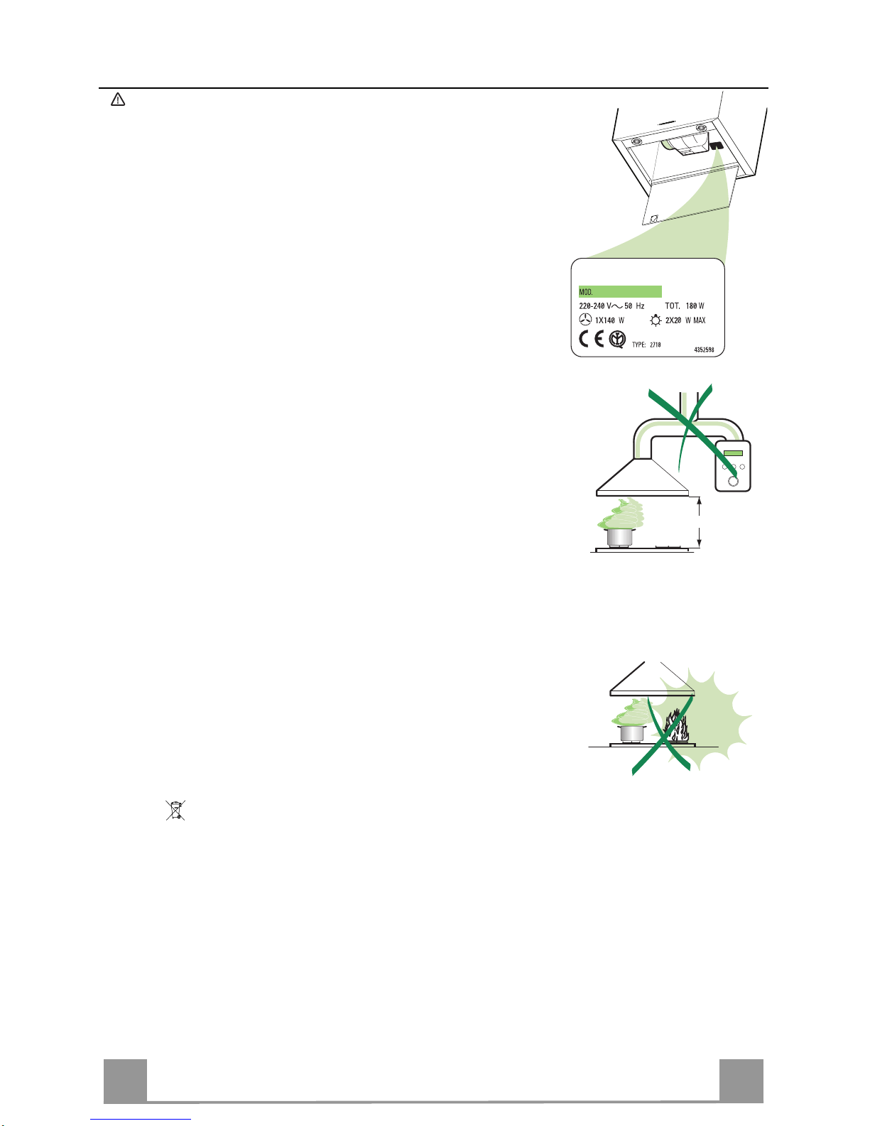
• The minimum safety distance between the cooker top and the extractor hood is 650
mm.
• Check that the mains voltage corresponds to that indicated on the rating plate fixed
to the inside of the hood.
• For Class I appliances, check that the domestic power supply guarantees adequate
earthing.
Connect the extractor to the exhaust flue through a pipe of minimum diameter 120
mm. The route of t he flue must be as s hor t as possible.
• Do not connect the extractor hood to exhaust ducts carrying combustion fumes
(boilers, fi r eplaces, etc.).
• If the extractor is used in conjunction with non-electrical appliances (e.g. gas burning appliances), a sufficient degree of aeration must be guaranteed in the room in
order to prevent the backflow of exhaust gas. The kitchen must have an opening
communicati ng directly with the open air in order to guarantee the entry of clean air.
USE
• The extractor hood has been designed exclusively for domestic use to eliminate
kitchen smells.
• Never use the hoo d f or purposes other t han for which i t has ben designed.
• Never leave high naked flames under the hood when it is in operation.
• Adjust the flame intensity to direct it onto the bottom of the pan only, making sure
that it does not engulf the sides.
• Deep fat fryers must be cont inuously monit ored during use: ov er heated oil can burst
into flames.
• Do not flambè under the range hood; r isk of fire
• This appliance is not intended for use by persons (including children) with reduced
physical, sensory or mental capabilities, or lack of experience and knowledge,
unless they have been given supervision or instruction concerning use of the appliance by a perso n responsible for their safety.
• Children should be supervised to ensure that they do not play with the applian ce.
MAINTENANCE
• Switch off or unplug the appliance from the mains supply before carrying out any
maintenance work.
• Clean and/or repl ace the Filter s af ter the specified time period.
• Clean the hood usi ng a damp cloth an d a neutral li quid detergent.
The symbol on the product or on its packaging indicates that this product may not be treated as
household waste. Instead it shall be handed over to the applicable collection point for the recycling
of electrical and electronic equipment. By ensuring this product is disposed of correctly, you will help
prevent potential negative consequences for the environment and human health, which could otherwise be caused by inappropriate waste handling of this product. For more detailed information about
recycling of this product, please contact your local city office, your household waste disposal service
or the shop where you purchased the product.
650 mm min.

EN
5
5
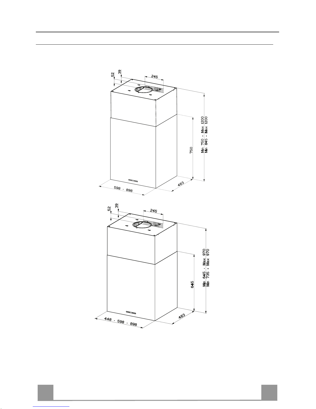
CHARACTERISTICS
Dimensions
The dimensions depend on the chosen version
*
**
*
**
* Dimensions of the hood in ducting version.
** Dimensions of the hood in recycling version.

EN
6
6
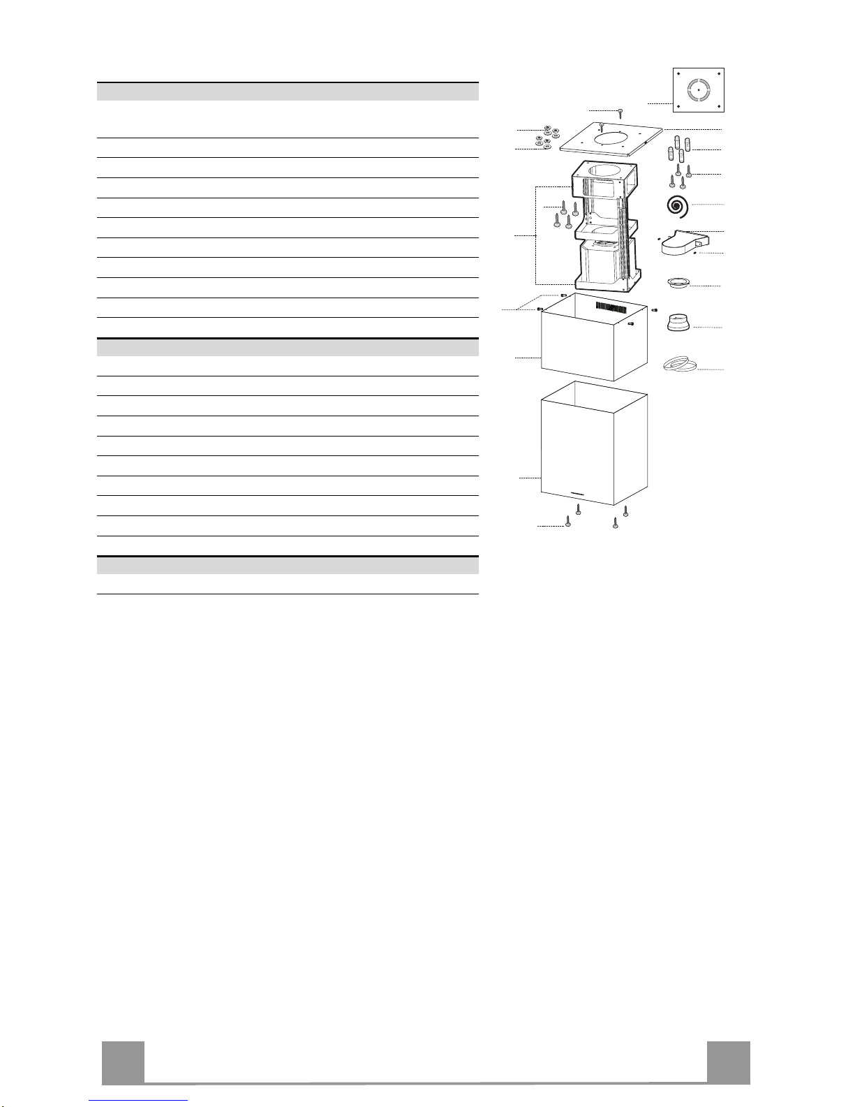
Components
Ref. Q.ty Product Components
1 1 Hood Body, complete with: Controls, Light, Blower,
Filters
2 1 Upper Chimney
7.1 1 Telescopic frame complete with extractor , consisting of:
7.1a 1 Upper frame
7.1b 1 Lower frame
9 1 Reducer Flange ø 150-120 mm (Optional)
13 1 Gasket
14 1 Hood Body Ai r Outlet Ext ension Piece
15 1 Air Outlet C onnection
25 2 Pipe clamps
26 1 Fixing Part of the upper Chimney
Ref. Q.ty Installation Components
11 4 Wall Plugs ø 10
12c 4 Screws 2,9 x 9,5
12f 4 Screws M6 x 15
12g 4 Screws M6 x 80
12h 4 Screws 5,2 x 70
12w 2 Screws M3 x 8
21 1 Drilling template
22 4 6.4 mm int. dia washers
23 4 M6 nuts
24 2 Fixing knobs for the air outlet connection piece
Q.ty Documentation
1 Instruction Manual
23
22
12h
11
15
24
1
12f
2
7.1
7.1b
7.1a
21
12g
12w
14
26
12c
13
9
25
EN
7
7
INSTALLATION
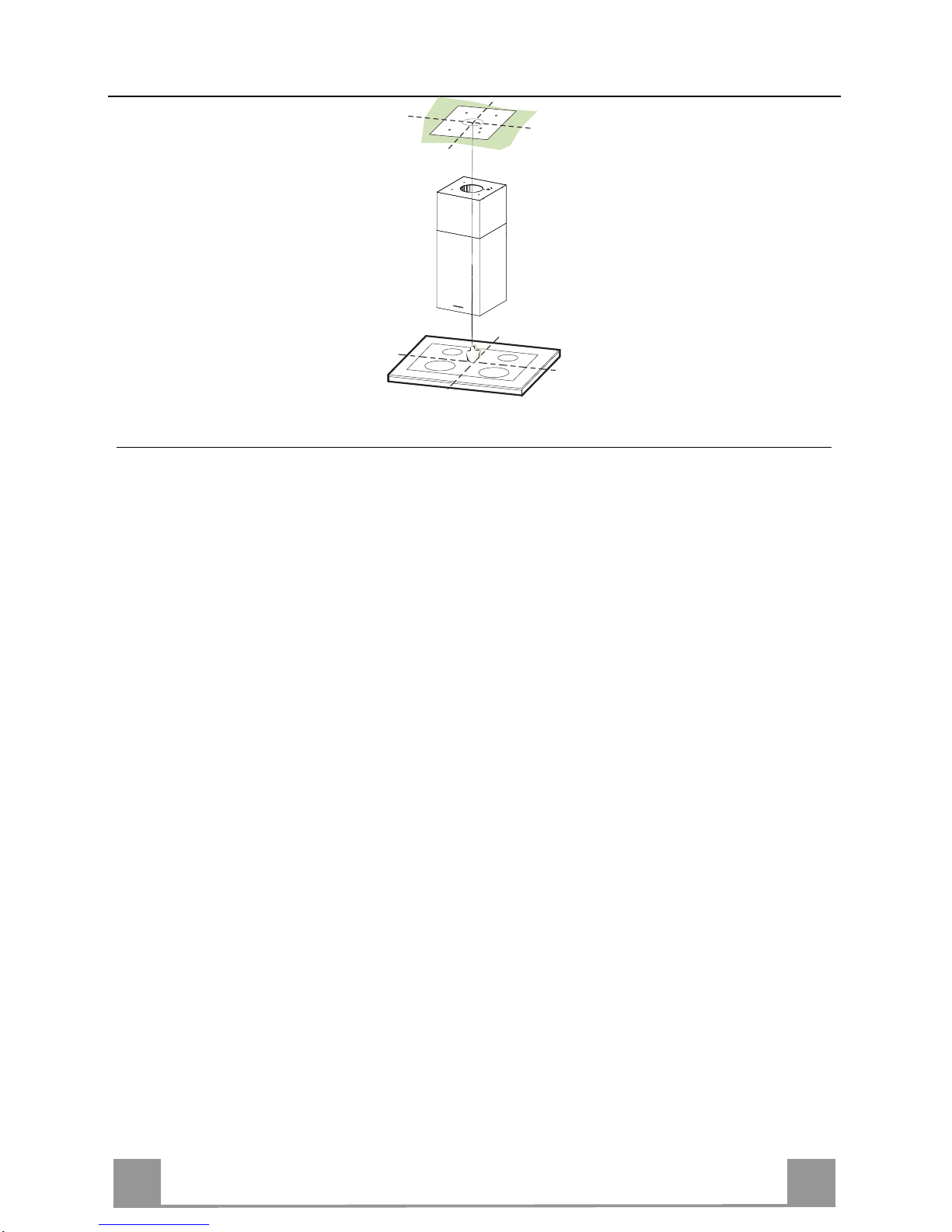
Drilling the Ceiling/shelf and fixing the frame
DRILLING TH E CEILING/SHELF
• Use a plumb line to mark the centre of the hob on the ceiling/support shelf.
• Place the drilling template 21 provided on the ceiling/support shelf, making sure that the
template is in the correct position by lining up the axes of the template with those of the hob.
• Mark the centres of the holes in the template.
• Drill the holes at the points marked:
• For concrete ceilings, drill for plugs appropriate to the screw size.
• For hollow brick ceilings with wall thickness of 20 mm: drill ø 10 mm(immediately insert
the Dowels 11 supplied).
• For wooden beam ceilings, drill according to the wood screws used.
• For wooden shelf, drill ø 7 mm.
• For the power supply cable feed, drill ø 10 mm.
• For the air outlet (Ducted Version), drill accord ing to the diameter of the extern al air exhaust duct connection.
• Insert two screws of the following type, crossing them and leaving 4-5 mm from the ceiling:
• For concrete ceilings, use the appropriate plugs for the screw size (not provided).
• for Cavity ceiling with inner space, with wall thickness of approx. 20 mm, Screws 12h,
supplied.
• For wooden beam ceilings, use 4 wood screws (not provided).
• For wooden shelf, use 4 screws 12g with washers 22 and nuts 23, provided.
EN
8
8
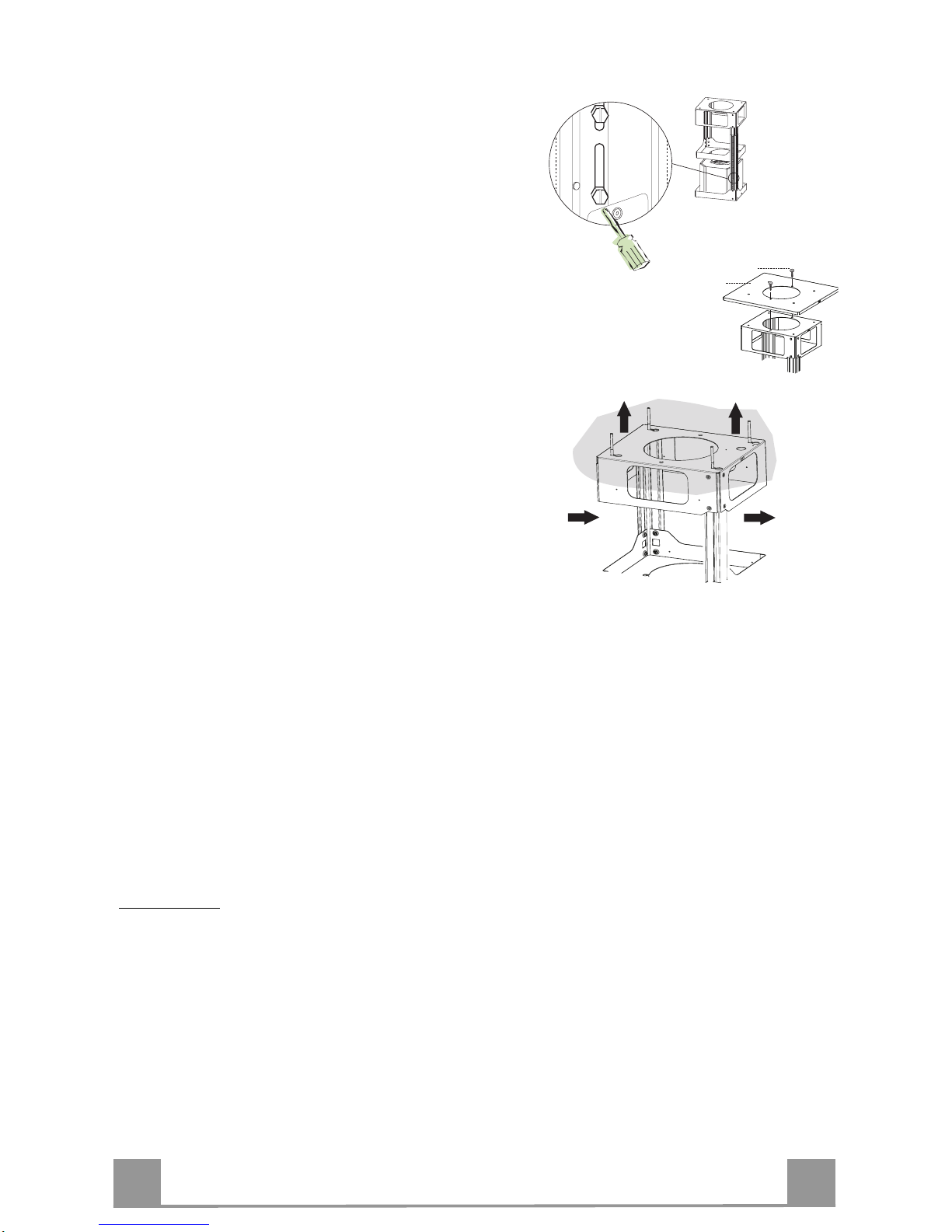
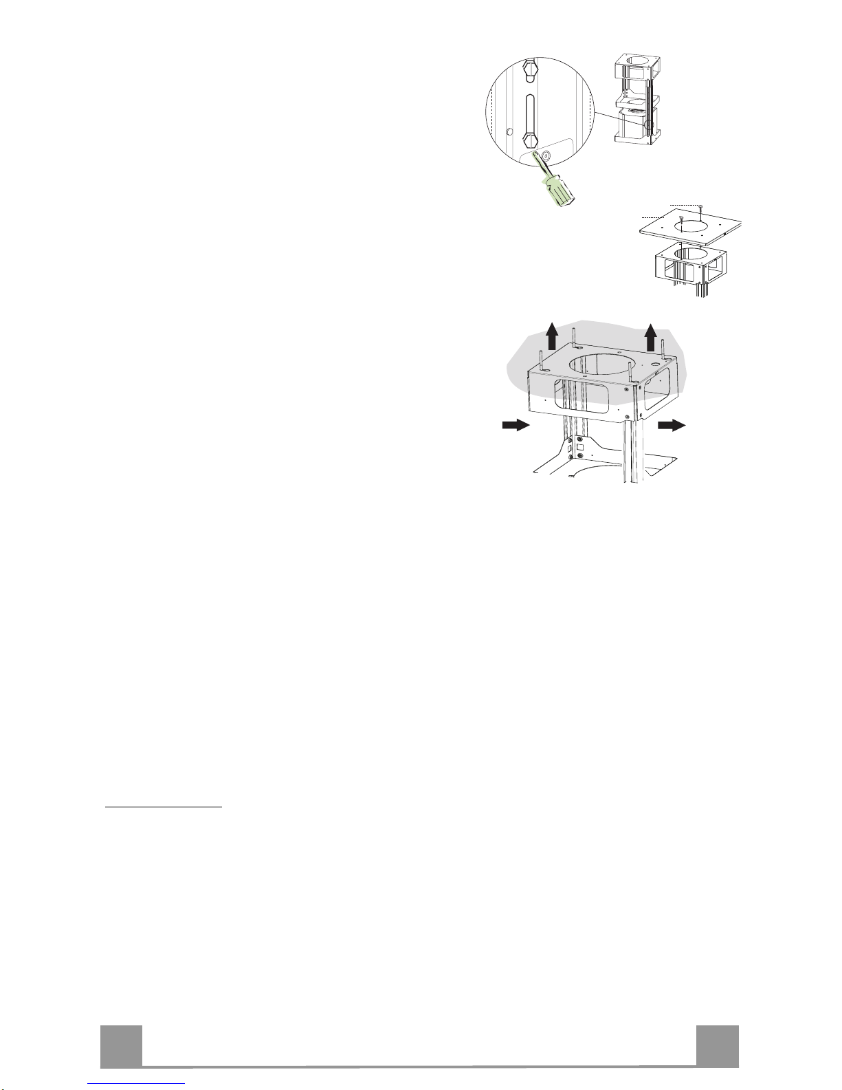
FIXING THE FRAME
If you wish to adjust the height of th e frame, proceed
as follows:
• Unfasten the metric screws joining the two columns,
located at the sid es of the frame.
• Adjust the frame to the height re
quired, then
replace all the screws removed as above.
• Fix the Fixing Part of the Upper Chimney 26 to the
hanging kit using the 2 screws 12w (M3 x 8).
• Lift up the frame, fit the frame slots onto the screws
up to the slot end positions.
• Tighten the two screws and fasten the other two
screws provided; before locking the screws com-
pletely, it is possible to adjust the frame by turning it,
making sure that the screws do not come out of their
housing in the adjustment slot.
• It is now possible to place and tighten the 4 safety
screws, Proceed as foll ows:
• drill the ceiling with a 10 mm ø bit taking as refer-
ence the holes of the side parts of the upper chimney fixing part.
• insert the 4 dowels (provided).
• insert the washers (provided) to the screws and
tighten the screws
• The Frame must be securely fastened so as to suppo rt
both the weight of the Hood and the stress caused by
occasional axial pressure against the fitted Appliance. After fixing, make sure that the base is stable
even when the Frame is subjected to lateral stress.
• If the Ceiling is not strong enough in the area where
the hood is to be fixed, the Installer must strengthen
the area using suitable plates and counterplates anchored to resistant structures.
2
2
1
1
12w
26
WARNING
: For the Recirculation version only: remove the sticker from
the slots on the upper chimney!
EN
9
9
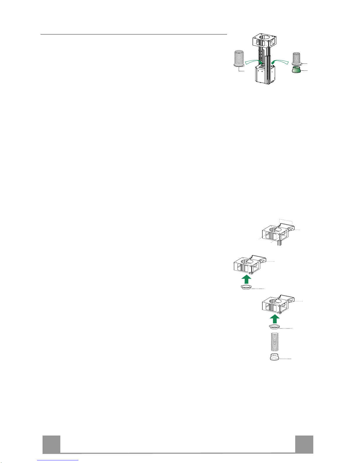
Ducted version air exhaust system Connection
When installing the ducted version, connect the hood to the
chimney using either a flexible or rigid pipe ø 150 or 120 mm,
the choice of which is left to the installer.
• To install a ø 120 mm air exhaust connection, insert the re-
ducer flange 9 on the hood body outlet.
• Fix the pipe using the pipe clamps 25 provided.
• Remove any activated charcoal filters.
9
ø 150
ø 120
25
25
RECIRCULATION VERSION AIR OUTLET
• Insert the reducer flange 9 on the air outlet of the extractor.
• Attach the adhesive Novastik gasket 13 to the air outlet connection 15 and fix this to the upper frame using the 2 knobs 24.
• Fix the air outlet conn ection exten si on p iece 14 to the air outlet
connection 15.
• Connect the hood air outlet to the flange in the lower part of
the junction using a rigid or flexible ø 120 tube (by installer’s
choice).
14
15
24
15
14
15
9

EN
110
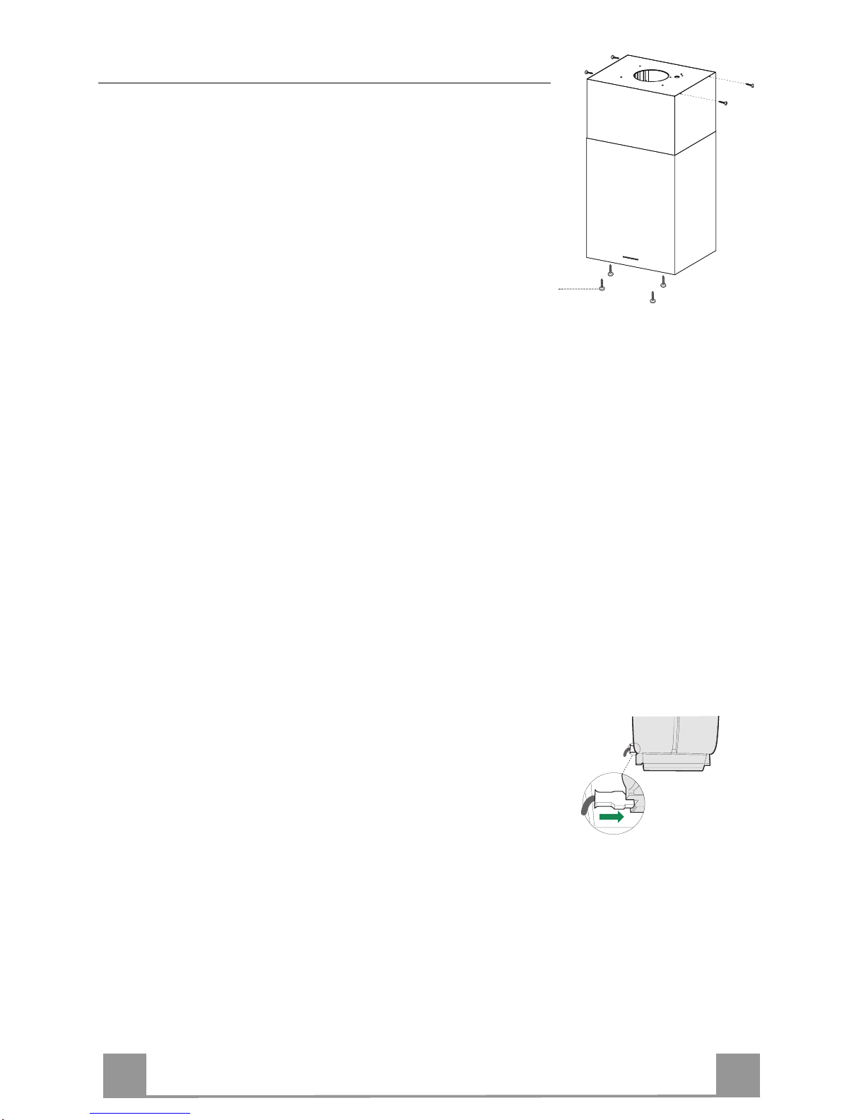
Flue assembly - Mounting the hood body
• Insert the upper duct and fix it on the top of the upper duct
connection using the 12c screws (2.9 x 9.5) supplied with the
appliance.
Recirculation version
• It is necess ary to make sure that t he air o utlet conn ection 15 is
placed correctly so that the air outlet grid in it correspond s to
that of the chimney.
• If the grids of the two parts are not corresponding to each
other, it will be necessary to remove the chimney and to adjust
the position of the air outlet connection 15, and at last to assembly the parts again by following the earlier indications.
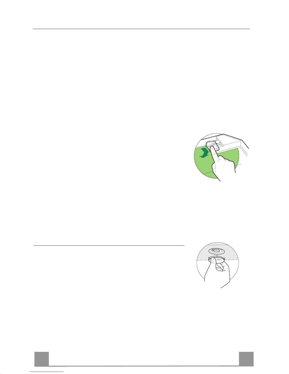
Before fixing the hood body to the frame:
• Open the suction panel by turning the specific knob.
• Disconnect the panel from the hood canopy by sliding the fixing pin lever.
• Remove the grease filters from the hood body.
• Remove any activated charcoal filters.
• From below, use the 4 screws 12f (M6 x 10) provided to fix the
hood body to the frame.
12c
12f
ELECTRICAL CONNECTION
• Connect the Hood to the mains power supply, inserting a twopole cut-out switch with contact aperture of at least 3 mm
along the line.
• Pull the Comfort Panel to open it, ensure that the supply cable
connector is properly inserted into the Suction device socket
• Join the connectors.
• Install the odour filter and the charcoal filter in case the hood is
to be used in recycling version.
• Install the grease filter again, and successively the suction
panel.
EN
111
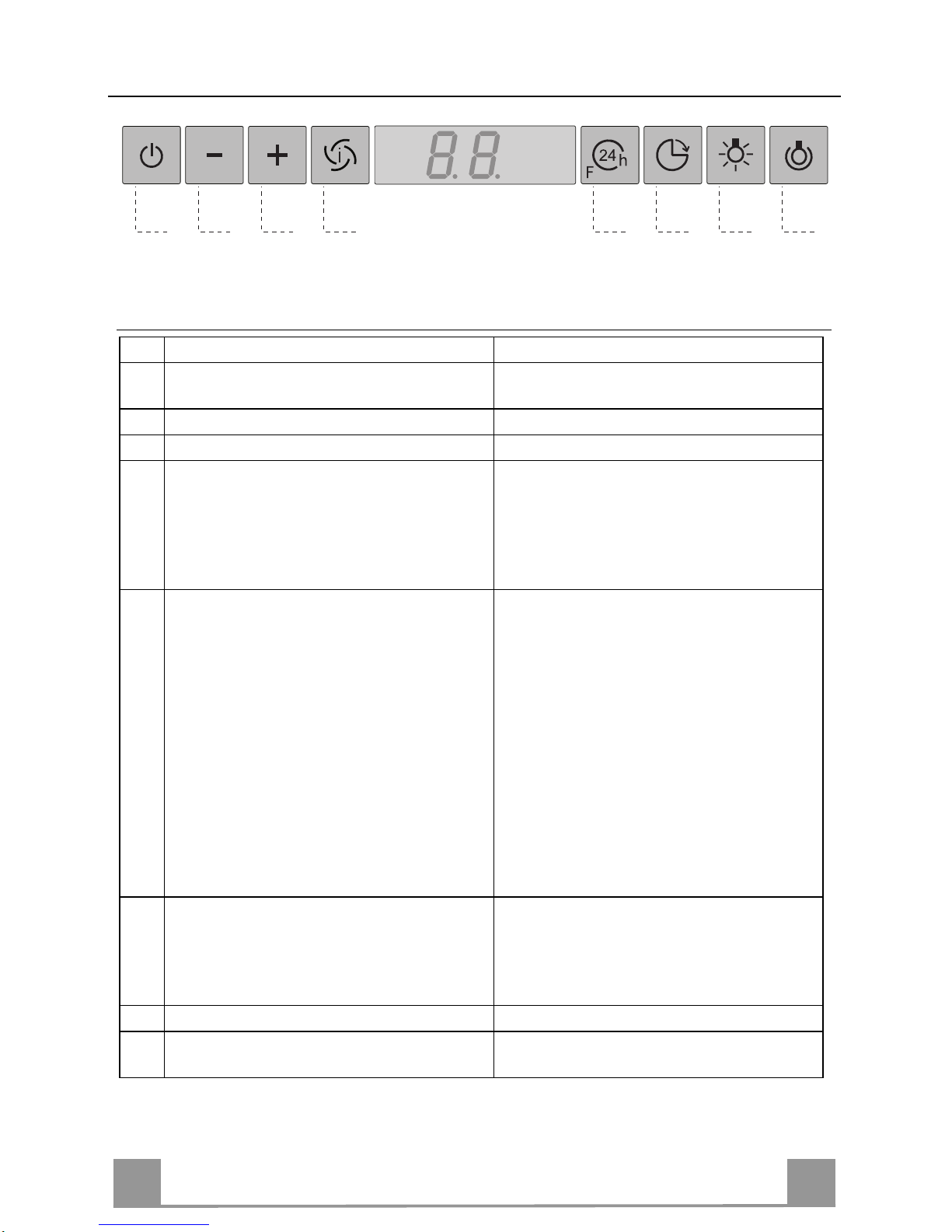
USE
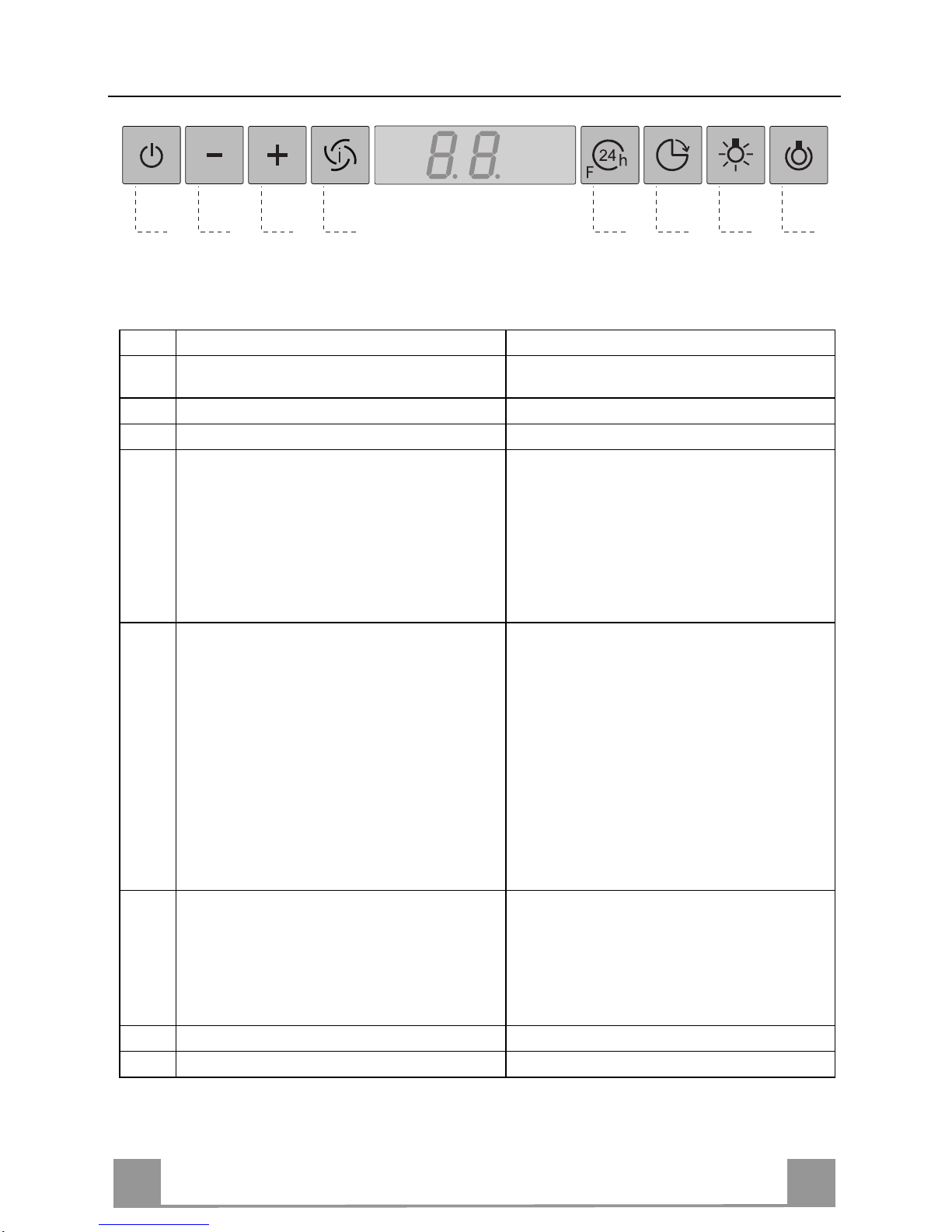
A B C D E F G H
Control board
Key Function Display
A
Switches th e extractor mot or on and off at the
latest selected speed
Indicates the selected speed.
B
Decreases the suction speed.
C
Increas es the suction speed.
D
By pressing this key it is possible to activate
the intensive speed from any previously selected sp eed. The inten sive speed can be a ctivated even when the mo tor is OFF. T his speed
has been timed at 10 minutes. After that time
the system activates automatically the latest
selected speed. This function is suitable for
cooking conditions when vapours and smells
are of the ut most emission.
HI appears. The spot down on the ri ght side
flashes once a second.
E
By pressing this key it is possible to set up the
motor to a suction speed at 100 m
3
/h lasting 10
minutes every hour. After this the motor
switches off automatically.
When the filter saturation is going on it is possible to reset the alarm by pressing this key for
about 3 sec onds. The indica tion is visible on ly
when the motor is off.
Indicates the 24-function. The spot down on
the right side flashes and the motor is on.
Once the process is finished the previous indi cation disa ppe ar s :
FF Indicates that the metal grease filters
saturation alarm has been triggered, and
the filt ers need to b e washed. The alarm
is triggered after 100 working hours.
EF Indicates that the charcoal filter satura-
tion alarm has been triggered, and the filter has to be replaced; the metal grease
filters must also be washed. The charcoal
filter is triggered after 200 working hours.
F
By pressing this key it is possible to set the
delayed shutdown of the appliance to 30 minutes. This function is suitable for a complete
elimination of the residual smells. It can be
activated at any position, and it is deactivated
by pressing the key again or by switching off
the motor.
Indicates altern ately the selec ted speed of the
hood and th e time left before the hood shutdown. The spot down on the right side fla shes.
G
Turns the light on and off .
H
Turns the li ght on and off at reduced intensity.
EN
112
MAINTENANCE
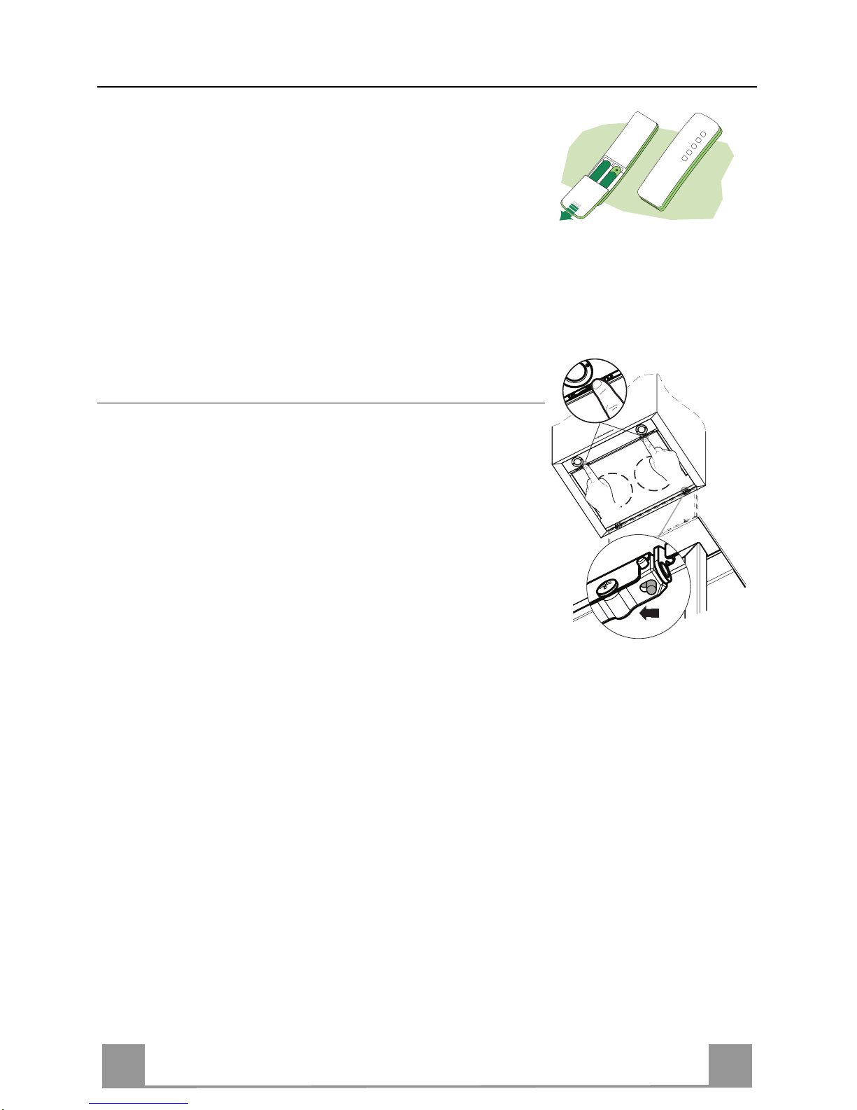
REMOTE CONTROL (OPTIONAL)
The appliance can be controlled using a remote control powered
by a 1.5 V carbon-zinc alkaline batteries of the standard LR03AAA type.
• Do not place the remote control near to heat sources.
• Used batteries must be disposed of in the proper manner.
Cleaning the Comfort Panels
• Pull the Comfort Panel to open it.
• Disconnect the panel from the hood canopy by sliding the fixing pin lever.
• The comfort panel must never be washed in a dishwasher.
• Clean the outside by using a damp cloth and neutral liquid detergent.
• Clean the inside as well by using a damp cloth and neutral detergent; do not use wet cloths or sponges, or jets of water; do
not use abrasive substances.
• When the above operation has been completed, hook the panel
back to the hood canopy and close it by turning the knob in the
opposite direction .

EN
113
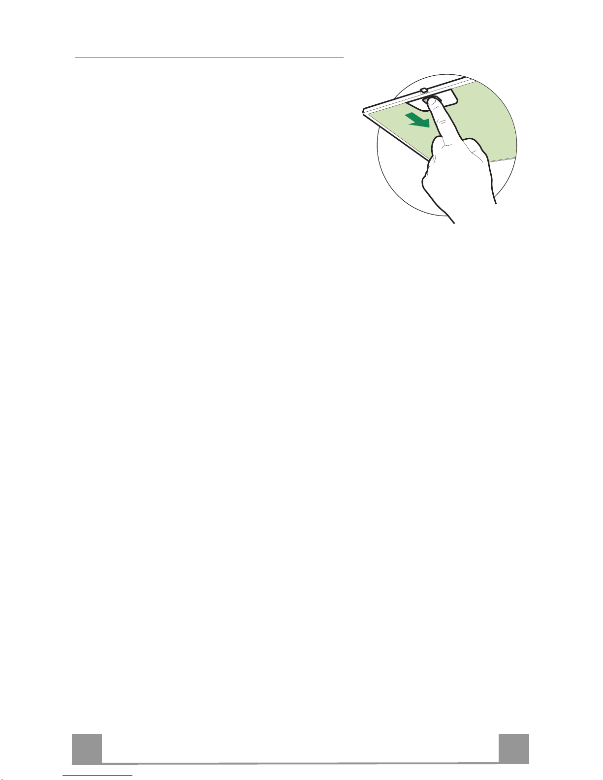
Metal grease filters
The Filters can be washed in the dishwashing. They
need to be wash ed when FF-sign appears on the display
or in any case every 2 months, or even more frequently
in case of particularly intensive use of the hood.
Alarm reset
• Switch off the hood and the lights. If the 24hfunction has been activated this has to be deactivated.
• Press the E-key till the display is unlit.
Cleaning the filters
• Pull the comfort panels to open them.
• Remove the filters one by one pushing them towards
the back side of the hood unit and simultaneously
pulling downwards.
• Any kind of bending of the filters has to be avoided
when washing them. Before fitting them again into
the hood make sure that they are completely dry.
(The colour of the filter surface may change throughout the time but this has no influence to the filter efficiency).
• When fitting the filters into the hood pay attention
that they are mounted in correct position the handle
facing outwards.
• Close the comfort panel.

EN
114
Charcoal filter (recycling version)
• This filter cannot be washed or regenerated. It must be replaced when the EF appears on th e
display or at least once every 4 months.
Activation of the alar m signal
• In the recycling version hoods the filter saturation alarm must be activated during the installation or later.
• Switch off the hood and the lights.
• Disconnect the hood from the mains supply.
• When restoring the connection press and hold B-key.
• When releasing the key two rotating rectangles appear on the display.
• Within 3 seconds press the B-key until a flashing confirmation appears on the dispaly:
• 2 flashes with EF - charcoal filter saturation alarm ACTIVATED
• 1 flash with EF - charcoal filter saturation alarm DEACTIVATED.
REPLACING THE CHARCOAL FILTER
Reset of the alar m sig nal
• Switch off the hood and the lighting. If the 24h-function has
been activated this has to be deactivated.
• Press the E-key until the display is unlit.
Replacing of the filter
• Open the comfort panels by pulling them downwards.
• Remove the metal grease filters.
• Remove the saturated charcoal filter by releasing the fixing
hooks.
• Fit the new filter and fasten it in its correct position.
• Put the metal grease filters in their seats.
• Close the comfort panels.
Lighting
LIGHT REPLACEMENT
20 W halogen light.
• Remove the snap-on lamp cover by levering it from under the
metal ring, supporting it with one hand.
• Remove the halogen lamp from the lamp holder by pulling
gently.
• Replace the lamp with a new one of the same type, making
sure that you insert the two pins properly into the housings on
the lamp holder.
• Replace the snap-on lamp cover.

IT 115
CONSIGLI E SUGGERIMENTI
Questo libretto di istruzioni per l'uso è previsto per più versioni dell'apparecchio.
Possibile che siano descritti singoli particolari della dotazione, che non riguardano il
Vostro apparecchio.
INSTALLAZIONE
• Il produtto re declina qualsiasi re sponsabilità per dann i dovuti ad installa zione non
corretta o non conforme alle regole dell’arte.
• La distanza minima di sicurezza tra il Piano di cottura e la Cappa deve essere di
650 mm.
• Verificare che la tensione di rete corrisponda a quella riportata nella targhetta posta
all’interno della Cappa.
• Per Apparecchi in Classe Ia accertarsi che l’impianto elettrico domestico ga rantis ca
un corretto sc ar ico a terra.
• Collegare la Cappa all’uscita dell’aria aspirata con tubazione di diametro pari o
superiore a 12 0 mm. Il percorso della tubazione deve essere il più breve possibi le.
• Non collegare la Cappa a condotti di scarico dei fumi prodotti da combustione (caldaie, caminetti, ecc.).
• Nel caso in cui nella stanza vengano utilizzati sia la Cappa che apparecchi non
azionati da energia elettrica (ad esempio apparecchi utilizzatori di gas), si deve
provvedere ad una aerazione sufficiente dell’ambiente. Se la cucina ne fosse
sprovvista, praticare un’apertura che comunichi con l’esterno, per garantire il richiamo d’aria pulita.
USO
• La Cappa è stata progettata esclusivamente per uso domestico, per abbattere gli
odori della cucina.
• Non fare mai uso i mproprio dell a Cappa.
• Non lasciare fiamme libere a fort e intensità sotto la Cappa in funzione.
• Regolare sempre le fiamme in modo da evitare una evidente fuoriuscita laterale
delle stesse ri spetto al fondo delle pentole.
• Controllare le friggitrici durante l’uso: l’olio surriscaldato potrebbe infiammarsi.
• Non preparare alimenti flambè sot to la cappa da cu cina; pericolo d'incendio.
• Questo apparecchio non deve essere utilizzato da persone (bambini inclusi) con
ridotte capacità psichiche, sensoriali o mentali, oppure da persone senza esperienza e conoscenza, a meno che non siano controllati o istruiti all’uso dell’apparecchio
da persone responsabili della loro sicurezza.
• I bambini devono essere supervisionati per assicurarsi che non giochino con
l’apparecchio.
MANUTENZIONE
• Prima di procedere a qualsiasi operazione di manutenzione, disinserire la Cappa
togliendo la spina elettrica o spegnendo l’interruttore generale.
• Effettuare u na sc rup o los a e tempestiva m anu te nz io ne dei Filtri secondo gli intervalli
consigliati.
• Per la pulizia delle superfici de lla Cappa è sufficien te utilizzare un panno u mido e
detersivo li quido neutro.
Il simbolo sul prodotto o sulla confezione indica che il prodotto non deve essere considerato
come un normale rifiuto domestico, ma deve essere portato nel punto di raccolta appropriato per il
riciclaggio di apparecchiature elettriche ed elettroniche. Provvedendo a smaltire questo prodotto in
modo appropriato, si contribuisce a evitare potenziali conseguenze negative per l’ambiente e per la
salute, che potrebbero derivare da uno smaltimento inadeguato del prodotto. Per informazioni più
dettagliate sul riciclaggio di questo prodotto, contattare l’ufficio comunale, il servizio locale di smaltimento rifiuti o il negozio in cui è stato acquistato il prodotto.
650 mm min.
IT 116
CARATTERISTICHE
Ingombro
Le dimensioni variano a seconda della versione scelta
*
**
*
**
* Dimensioni per cappa in versione aspirante.
** Dimensioni per cappa in versione filtrante.
IT 117
Componenti
Rif. Q.tà Componenti di Prodotto
1 1 Corpo Cappa completo di: Comandi, Luce,Gruppo
Ventilatore, Filtri, Camino Infer iore
2 1 Camino Superiore
7.1 1 Traliccio telesco pico completo di Aspir atore,formato da:
7.1a 1 Traliccio superiore
7.1b 1 Traliccio inferiore
9 1 Flangia di Riduzione ø 1 50-120 mm (Opzionale)
13 1 Guarnizione Adesiva Novastik
14 1 Flangia per Raccordo Uscita Aria
15 1 Raccordo Uscita Aria
25 2 Fascette stringitubo
26 1 Attacco Camino Superiore
Rif. Q.tà Componenti di Installazione
11 4 Tasselli ø 10
12c 4 Viti 2,9 x 9,5
12f 4 Viti M6 x 10
12g 4 Viti M6 x 80
12h 4 Viti 5,2 x 70
12w 2 Viti M3 x 8
21 1 Dima di foratura
22 4 Rondelle øi 6,4
23 4 Dadi M6
24 2 Pomelli fissaggio R accordo Uscita Aria
Q.tà Documentazione
1 Libretto Istruzioni
23
22
12h
11
15
24
1
12f
2
7.1
7.1b
7.1a
21
12g
12w
14
26
12c
13
9
25

IT 118
INSTALLAZIONE
Foratura Soffitto/Mensola e Fissaggio Traliccio
FORATURA SOFFITTO/MENSOLA
• Con l’ausilio di un Filo a piombo riportare sul Soffitto/Mensola di supporto il centro del
Piano di Cottura.
• Appoggiare al Soffitto/Mensola la Dima di Foratura 21 in dotazione, facendo coincidere il
suo centro al centro proiettato e allineando gli assi della Dima agli assi del Piano di Cottura.
• Segnare i centri dei Fori della Dima.
• Forare i punti seguenti:
• Soffitto in Calcestruzzo massiccio: secondo Tasselli per Calcestruzzo impiegati.
• Soffitto in Laterizio a camera d’aria, con spessore resistente di 20 mm: ø 10 mm (inserire
subito i Tasselli 11 in do ta z ione ) .
• Soffitto in Travatura di Legno: secondo Viti per Legno impiegate.
• Mensola in Legno: ø 7 mm.
• Passaggio del Cavo elettrico di Alimentazione: ø 10 mm.
• Uscita Aria (Versione Aspirante): secondo diametro del collegamento alla Tubazione di
Evacuazione Esterna.
• Avvitare, incrociandole e lasciando 4-5 mm dal soffitto, due viti:
• per Calcestruzzo massiccio, Tasselli per Calcestruzzo, non in dotazione.
• per Laterizio a camera d’aria, con sp essore resisten te di 20 mm circa, Viti 12h, in dotazio-
ne.
• per Travatura di legno, Viti per legno, non in dotazione.
• per Mensola in Legno, viti 12g con Rondelle 22 e Dadi 23, in dotazione.
IT 119
FISSAGGIO TRALICCIO
Nel caso in cui si vogl ia regolare l’altezza del t r aliccio :
• Svitare le viti che uniscono le due colonne.
• Regol are il tral iccio all ’altezza desi derata e riavvit are
le viti.
• Unire l’Attacco Camino Superiore 26 al traliccio superiore tramite le 2 Viti 12w (M3 x 8).
• Sollevare il traliccio, incastrare le asole sulle viti e
scorrere fino a battuta. A questo punto il traliccio si
regge da solo
• Stringere le due viti e avvitare le altre due in dotazione sulla piastra superiore;
Prima di serrare definitivamente le viti è possibile
effettuare delle regolazioni spostando il traliccio,facendo attenzione che le viti non escano dalla
sede dell’asola di regolazione.
• Ora è po ssibile avvitare 4 viti di sicurezza,per farlo,
procedere come ind i cato:
• forare con una punta ø 10 il soffitto utilizzando i
fori posti sui lati dell’at t acco camino superiore.
• Inserire 4 tasselli in dotazione
• Inserire le Rondelle in dotazione nelle viti e serrare.
• Il fissaggio del Traliccio deve essere sicuro in relazione sia al peso della Cappa sia alle sollecitazioni
causate da occasionali spinte laterali all’Apparecchio
montato. A fissaggio avvenuto verificare quindi che
la base sia stab ile anche se il Tral iccio è solleci tato a
flessione.
• In tutti i casi in cui il Soffitto non fosse sufficientemente robusto sul punto di sospensione, l’Installatore
dovrà provvedere a irrobustirlo con opportune piastre
e contropiastre ancorate a parti strutturalmente resistenti.
2
2
1
1
12w
26
ATTENZIONE
: Solo per la Versione f iltrant e rimuovere l’etich etta adesi-
va dalle asole sul camino superiore!

IT 220
Connessione Uscita aria Versione Aspirante
Per installazione in Versione Aspirante collegare la Cappa alla
tubazione di uscita per mezzo di un tubo rigido o flessibile di
ø 150 o 120 mm, la cui scelta è lasciata all’installatore.
• Per collegamento con tubo ø 120 mm, inserire la Flangia di
riduzione 9 sull’Uscita del Corpo Cappa.
• Fissare il tubo con adeguate fascette stringitubo 25 in dotazio-
ne.
• Rimuovere eventuali filtri al carbone attivo.
9
ø 150
ø 120
25
25
USCITA ARIA VERSIONE FILTRANTE
• Inserire la Flangia di riduzione 9 sull’uscita dell’Aspiratore.
• Attaccare la Guarnizione Adesiva Novastik 13 sul Raccordo
Uscita Aria 15 e fissarlo al trali ccio superiore tramite i 2 Po melli 24.
• Attac care la Flangia Raccordo Uscit a Aria 14 al Raccordo Uscita Aria 15.
• Collegare l’uscita aria della cappa con la flangia posta sotto al
raccordo per mezzo di un tubo rigido o flessibile ø 120mm, la
cui scelta è lasciata all’installatore.
14
15
24
15
14
15
9
IT 221
Montaggio Camino e Fissaggio Corpo Cappa
• Inserire il Camino superiore e fissarlo nella parte superiore
all’Attacco Camino Superiore con le Viti 12c (2,9 x 9,5) in dotazione.
Versione filtrante
• Assicurarsi che il Raccordo Uscita Aria 15 sia in corrispondenza della Grigliatura del Camino.
• Se così non fosse, rimuovere il camino e aggiustare la posizione del Raccordo Uscit a Aria 15; rimontare quindi i particolari
come prima descritto.
Prima di fissare il Corpo Cappa al Traliccio:
• Aprire il pannello aspirante tirandolo.
• Sganciare il pannello dal corpo cappa facendo scorrere
l’apposita leva del perno di fissaggio.
• Togliere i Filtri antigrasso dal Corpo Cappa.
• Togliere eventuali Filtri Antiodore al Carbone attivo.
• Fissare quindi dal sotto, con 4 viti 12f in dotazione, il Corpo
Cappa al Traliccio predisposto.
12c
12f
CONNESSIONE ELETTRICA
• Collegare la Cappa all’Alimentazione di Rete interponendo un
Interruttore bipolare con apertura dei contatti di almeno 3 mm.
• Aprire il Pannello Aspirante e i filtri antigrasso, assicurarsi che
il connettore del Cavo d i alimentazione sia corret tamente inserito nella presa dell’Aspiratore
• Effettuare i collegamenti dei Connettori
• Per la Versione Filtrante montare il Filtro Antiodore al Carbone attivo.
• Rimontare i Filtri Antigrasso e il Pannello Aspirante.
IT 222
USO
A B C D E F G H
Quadro comandi
Tasto Funzione Display
A
Accende e spegne il motore di aspirazione
all’ultima velocità utilizzata.
Visualizza la velocità impostata
B D ecrementa la velocità di esercizio.
C Incrementa la velocità d i esercizio.
D
Attiva la velocità intensiva da qualsiasi velocità anche da motore spento, tale velocità è
temporizzata a 10 minuti, al termine del tempo
il sist ema ritorn a alla veloc ità precedent ement e
impostata. Adatta a fronteggiare le massime
emissioni di fumi di cottu r a.
Visualizza HI e il punto in basso a dest ra lampeggia una volta al secondo.
E
Attiva il motore ad una velocità che consente
un’aspirazione di 100 m
3
/h per 10 minuti ogni
ora, terminati il motore si ferma.
Con l’allarme filtri in corso premendo il tasto
per circa 3 secondi si effettua il reset dell’allarme. Tali segnalazioni sono visibili solo a
motore spento.
Visualizza 24 e il punto in basso a destra lampeggia, mentre il motore è in funzione
Terminata la procedura si spegne la segnalazione precedentem ente visualizzata:
FF segnala la necessità di lavare i filtri anti-
grasso metallici. L’allarme entra in funzione dopo 100 ore di lavoro effettivo
della Cappa.
EF segnala la necessità di sostituire i filtri al
carbone at tivo e devono a nche essere lavati i filtri antigrasso metallici. L’allarme
entra in funzione dopo 200 ore di lavoro
effettivo della Cappa.
F
Attiva lo spegnimento automatico ritardato di
30’. Adatto per completare l’eliminazione di
odori residui. Attivabile da qualsiasi posizione,
si disattiva pr emendo il tas to o spe g nendo il
motore.
Visualizza alternativamente la velocità di esercizio e il tempo rimanente allo spegnimen to
della cappa. Il punto in basso a destra lampeggia.
G Accende e spegne l’impianto di illuminazione.
H
Accende e spegne l’impi anto di illuminazione
ad intensit à ri do tt a.

IT 223
MANUTENZIONE
TELECOMANDO (OPZIONALE)
Questo apparecchio può essere comandato per mezzo di un telecomando, alimentato con pile alcaline zinco-carbone da 1,5 V del
tipo standard LR03-AAA.
• Non riporre il telecomando in prossimità di fonti di calore.
• Non disperdere le pile nell’ambiente, depositarle negli appositi
contenitori.
Pulizia dei Comfort Panel
• Aprire il Comfort Panel tirandolo.
• Sganciare il pannello dal corpo cappa facendo scorrere
l’apposita leva del perno di fissaggio.
• Il comfort panel non va assolutamente lavato in lavastoviglie.
• Pulirlo esternamente con un panno umido e detersivo liquido
neutro.
• Pulirlo anche internamente utilizzando un panno umido e detergente neutro; non utilizzare panni o spugne bagnate, n é getti
d’acqua; non utilizzare sostanze abrasive.
• Ad operazione ultimata riagganciare il pannello al corpo cappa
e richiuderlo.
.
IT 224
Filtri antigrasso metallici
Sono lavabili anche in lavastoviglie, e necessitano di
essere lavati quando sul display appare FF o almeno
ogni 2 mesi circa di utilizzo o più frequentemente, per
un uso particolarmente intenso.
Reset del segnale di allarme
• Spegnere le Luci e il Motore di aspirazione, quindi
qualora fosse attivata la funzione 24h disattivarla.
• Premere il tasto E sino allo spegnersi del display.
Pulizia Filtri
• Aprire i Comfort Panel tirandoli.
• Togliere i Filtri uno alla volta, spingendoli verso la
parte posteriore del gruppo e tirando contemporaneamente verso il basso.
• Lavare i Filtri evitando di piegarli, e lasciarli asciugare prima di rimontarli. (Un’eventuale cambiamento
del colore della superficie del filtro, che potrebbe verificarsi nel tempo, non pregiudica assolutamente
l’efficienza dello stesso.)
• Rimontarli facendo attenzione a mantenere la maniglia verso la parte visibile esterna.
• Richiudere i comfort panel.
IT 225
Filtri antiodore al Carbone attivo (Versione Filtrante)
• Non è lavabile e non è rigenerabile, va sostituito quando sul display appare EF o almeno
ogni 4 mesi.
Attivazione del segnale di all arme
• Nelle Cappe in Versione Filtrante, la segnalazione di Allarme saturazione Filtri va attivata al
momento dell’installazione o successivamente.
• Spegnere le Luci e il Motore di asp irazione.
• Scollegare la cappa dall’alimentazione di rete.
• Ripristinare il collegamento tenendo premuto il tasto B.
• Rilasciando il tasto sul display compaiono due rettangoli in rotazione.
• Entro 3 secondi premere il Tasto B sino alla conferma che appare sul display:
• 2 lampeggi scritta EF - Allarme saturazione Filtro Carbone attivo ATTIVATO
• 1 lampeggio scritta EF - Allarme saturazione Filtro al Carbone attivo DISATTIVATO.
SOSTITUZIONE FILTRO ANTIODORE AL CARBONE ATTIVO
Reset del segnale di allarme
• Spegnere le Luci e il Motore di aspirazione, quindi qualora
fosse attivata la funzione 24h disattivarla.
• Premere il tasto E sino allo spegnersi del display.
Sostituzione Filtro
• Aprire i Comfort Panel tirandoli.
• Togliere i Filtri antigrasso metallici.
• Rimuovere il Filtro antiodore al Carbone attivo saturo, agendo
sugli appositi agganci.
• Montare il nuovo Filtro agganciandolo nella sua sede.
• Rimontare i Filtri antigrasso metallici.
• Richiudere i Comfort Panel.
Illuminazione
SOSTITUZIONE LAMPADE
Lampade alogene d a 20 W
• Togliere il bloccavetro metallico a pressione facendo leva sotto
la ghiera, sostenendolo con una man o.
• Estrarre la lampadina alogena d al portalampada.
• Sostituirla con una nuova lampadina di uguali caratteristiche,
facendo attenzione ad inserire correttamente i due spinotti nella
sede del portalampade.
• Rimontare il bloccavetro a pressione.

FR
226
CONSEILS ET SUGGESTIONS
La présente notice d'emploi vaut pour plusieurs versions de l'appareil. Elle peut contenir des
descriptions d 'accessoires ne figurant pas dans votre appareil.
INSTALLATION
• Le fabricant dé c line toute responsabilité en cas de dommage dû à une installation non correcte ou non conforme aux règles de l’a rt.
• L a dist a nc e mini m ale de s éc urit é entr e l e pl an de c uiss on et la hot t e doi t êtr e d e 6 50 mm au
moins.
• Vérifier que la tensio n du s ecteur correspond à la valeur qui figure sur la plaquette apposée à
l’intérieur de la hotte.
• Pour les Appareils appartenant à la Ière Classe, veiller à ce que la mise à la terre de
l’installation élect rique do mestique ait été effe ctuée confo rmément aux nor mes en vigueur.
• Connecter la hotte à la sort ie d’air aspiré à l’aide d’une tu yauterie d’un diamè tre égal ou supérieur à 120 mm. Le parcours de la tuyauterie doit être le plus court possible.
• Eviter de connecter la hotte à des conduites d’évacuation de fumées issues d’une combustion tel que (Chaudière, ch eminée, etc…).
• Si vous utilisez des appareils qui ne fonctionnent pas à l’électricité dans la pièce ou est installée la hotte (par exemple: des appareils fonctionnant au gaz), vous devez prévoir une aération suffisante du milieu. Si la cuisine en est dépourvue, pratiquez une ouverture qui communique avec l’extér ieur pour garantir l’infiltration de l’air pur.
UTILISATION
• La hotte a été conç ue exclusivement pour l’ usage domestiq ue, dans le but d’ éliminer les
odeurs de la cuisine.
• Ne jamais utiliser abusivement la hotte.
• Ne pas laisser les flammes libres à forte intensité quand la hotte est en service.
• To ujours régl er les flammes de manière à éviter tout e sortie latér ale de ces d ernières par
rapport au f ond des marmites.
• Contrôler les friteuses lors de l’utilisation car l’huile surchauffée pou rrait s’enf lammer.
• Ne pas préparer d’aliments flambé s sous la hotte de cuisine : risque d’in cendie
• Cet appareil ne doit pas être utilisé par des personnes (y compris les enfants) ayant des
capacit és psychi ques, s ensori elles o u mental es rédui tes, ni p ar des p ersonne s n’ayan t pas
l’expérience et la connaissance de ce type d’appareils, à moins d'être sous le contrôle et la
formation de personnes respon sables de leur sécurité.
• Les enfants doivent être surveillés pour s'assurer qu'ils ne jouen t pas avec l'appa reil.
ENTRETIEN
• Avant d e procé der à tout e opérati on d’e ntretie n, retirer la hotte en retiran t la fich e ou en actionnant l’interrupt eu r général.
• Effectuer un entretien scrupuleux et en temps dû des Filtres, à la cadence conseillée.
• Pour le nettoyage des surfaces de la hotte, il suffit d’utiliser un chiffon humide et détersif
liquide neutre.
Le symbole sur le produit ou son emballage indique que ce produit ne peut être traité comme déchet
ménager. Il doit plutôt être remis au point de ramassage concerné, se chargeant du recyclage du matériel
électrique et électronique. En vous assurant que ce produit est éliminé correctement, vous favorisez la
prévention des conséquences négatives pour l’environnement et la santé humaine qui, sinon, seraient le
résultat d’un traitement inapproprié des déchets de ce produit. Pour obtenir plus de détails sur le recyclage
de ce produit, veuillez prendre contact avec le bureau municipal de votre région, votre service d’élimination
des déchets ménagers ou le magasin où vous avez a cheté le produit.
650 mm min.
 Loading...