

Page 1
Manuale d’istruzioni
Piano di cottura da incasso
Operating and maintenance instruction for hobs
Electric hobs
FHBP 604 4I T B2 XS
2
15
1
Page 2

Gentile cliente
Istruzioni d’uso
Istruzioni di collegamento
Targhetta
Protezione dal pericolo
d’incendio
Il piano cottura in vetroceramica ad incasso è destinato all’uso domestico. Per
l’imballaggio dei nostri prodotti usiamo materiali che rispettano l’ambiente, sono
riciclabili ed idonei ad essere deposti o distrutti.
Per questo motivo abbiamo segnalato adeguatamente i materiali per l’imballo.
Quando l’apparecchio non sarà più utilizzato e sarà d’imgombro, si raccomanda
di consegnarlo ad una ditta per il recupero d’apparecchi »fuori uso« in modo che
l’ambiente non venga inquinato.
Le istruzioni d’uso sono destinate al consumatore.Descrivono l’apparecchio e il
suo utilizzo. All’interno sono descritti vari tipi/modelli d’apparecchi, per cui
potreste trovare descrizioni di funzioni che il Vostro apparecchio non possiede.
Il collegamento deve essere eseguito secondo il capitolo Collegamento alla rete
elettrica e le norme in vigore. Il lavoro può essere eseguito solo da personale
specializzato.
La targhetta con i dati di base è posizionata nella parte inferiore dell’apparecchio.
L’apparecchio può essere incassato da una parte vicino ad un mobile più alto di
esso e dall’altra parte vicino ad un mobile di altezza uguale all’apparecchio.
Avvertenze importanti
Piano cottura in vetroceramica
Gestione piano cottura
Procedura di configurazione
Limitazione della potenza
Segnalazione errori
Pulizia e manutenzione piano cottura
Incasso piano cottura
Collegamento alla rete elettrica
Caratteristiche tecniche
3
6
6
9
9
10
11
12
13
14
2
Page 3
AVVERTENZE
IMPORTANTI
• L’incasso e il collegamento elettrico dell’apparecchio alla rete può essere
eseguito solo da personale specializzato.
• Alcune parti dell’apparecchio si scaldano durante il funzionamento.
Fate attenzione ai bambini, non lasciateli nelle vicinanze dell’apparecchio e
avvertiteli del pericolo d’ustioni.
• Il grasso surriscaldato si può facilmente incendiare. Usate massima cautela
durante la preparazione degli alimenti che necessitano utilizzo di lardo o d’olio
(p.e. patatine fritte).
• Le zone cottura non devono funzionare a vuoto, senza le pentole.
• Non usare l’apparecchio per riscaldare l’ambiente.
• Il piano in vetroceramica non deve essere usato come piano di lavoro. Gli
oggetti appuntiti possono graffiare la superficie.
• Non posare sul piano a induzione oggetti come coltelli, forchette, cucchiai o
coperchi perchè si possono surriscaldare.
• La preparazione di cibo nei contenitori di plastica e di alluminio è vietata. Sul
piano cottura in vetroceramica caldo non si devono mettere oggetti in plastica e
di alluminio.
• Attenzione al cavo elettrico di qualche altro apparecchio che non venga in
contatto con le zone cottura calde.
• Non conservare sotto l’apparecchio oggetti sensibili a sbalzi di temperatura
(p.e.detersivi, spray etc).
• Non usare il piano cottura in vetroceramica rotto o screpolato. Se notate
qualche difetto interrompete immediatamente l’alimentazione elettrica.
• In caso di disturbi staccare il cavo di alimentazione elettrica e chiamare il
Servizio Assistenza.
• L’apparecchio non deve essere pulito con apparecchi a vapore o ad alta
pressione.
• L’apparecchio é prodotto secondo gli standard di sicurezza in vigore; malgrado
questo, non consigliamo l’utilizzo di esso senza sorveglianza, da parte di
persone con ridotte capacità fisiche, movimentali o mentali, oppure delle persone
senza esperienza o conoscenza. Lo stesso consiglio vale per l’utilizzo
dell’apparecchio da parte di persone minorenni.
Il simbolo sul prodotto o sulla confezione indica che il prodotto non deve
essere considerato come un normale rifiuto domestico, ma deve essere
portato nel punto di raccolta appropriato per il riciclaggio di
apparecchiature elettriche ed elettroniche.
Provvedendo a smaltire questo prodotto in modo appropriato, si
contribuisce a evitare potenziali conseguenze negative per l’ambiente e per
la salute, che potrebbero derivare da uno smaltimento inadeguato del
prodotto. Per informazioni più dettagliate sul riciclaggio di questo prodotto,
contattare l’ufficio comunale, il servizio locale di smaltimento rifiuti o il
negozio in cui è stato acquistato il prodotto.
3
Page 4
Principio funzionamento
piano cottura
Livelli cottura
CONSIGLI PER IL
RISPARMIO ENERGETICO
• Nel pannello in vetroceramica sono stati inserite quattro zone cottura.
La superficie è piatta, senza bordi, dove potrebbe accumularsi la sporcizia.
• Il pannello di cottura è dotato di zone cottura a induzione altamente funzionanti.
Il calore si forma direttamente nel fondo della pentola, dove serve di più, senza
inutili perdite attraverso la superficie in vetroceramica. Così il consumo
energetico è molto minore rispetto alle zone cottura standard che funzionano sul
principio di riscaldamento.
• La superficie in vetroceramica non si scalda direttamente, ma solamente con il
calore che ritorna dalla pentola direttamente riscaldata. Questo calore è indicato
(dopo lo spegnimento) come »il calore residuo«. Il riscaldamento nella zona
cottura a induzione è assicurato dalla bobina a induzione, inserita sotto la
superficie in vetroceramica. La bobina stabilizza il campo magnetico; per quello
si trovano sul fondo delle pentole (che possono essere magnetizzate) i vortici
della corrente, che le scaldano.
IMPORTANTE!
Se sul piano cottura caldo si rovescia lo zucchero o il cibo particolarmente
zuccherato bisogna pulirlo subito con un raschietto, anche se è ancora caldo.
Così evitate possibili danneggiamenti della superficie in vetroceramica. Non
pulire la superficie in vetroceramica ancora calda con i prodotti chimici perchè
quest’ultima si può danneggiare.
La potenza delle zone cottura può essere selezionata su nove livelli differenti.
Nella tabella sono descritti gli esempi delle singole impostazioni.
Livello Intenzione
0
1-2
3
4-5
6
7-8
9
A
Spegnimento, uso del calore residuo
Conservazione cibo caldo, cottura piccole quantità di cibo
Cottura lenta (proseguimento cottura dopo riscaldamento
forte)
Cottura lenta grandi quantità
Cottura per arrostire,rosolare il cibo
Cottura per arrostire il cibo
Inizio cottura, arrosto
Riscaldamento veloce automatico
•Fate attenzione al momento d’acquisto delle pentole, perché il diametro indicato
della pentola corrisponde al diametro superiore o coperchio che è sempre
maggiore del fondo della pentola.
• Le pentole a pressione sono particolarmente indicate per il risparmio poichè
grazie alla pressione interna elevata, riescono a finire la cottura in tempo minore.
Per il tempo di cottura più breve, anche le vitamine degli alimenti si conservano
meglio.
• Fate attenzione che nella pentola a pressione ci siano sempre abbastanza
liquidi perché altrimenti potrebbe verificarsi il surriscaldamento che
danneggierebbe sia la pentola che il piano cottura.
• Coprire sempre le pentole con adeguati coperchi.
• Usate le pentole adeguate per la quantità di cibo che cucinate. Se usate solo la
metà della pentola, sprecherete tanta energia elettrica.
4
Page 5
PIANO COTTURA IN VETROCERAMICA
Elementi di gestione piano
cottura
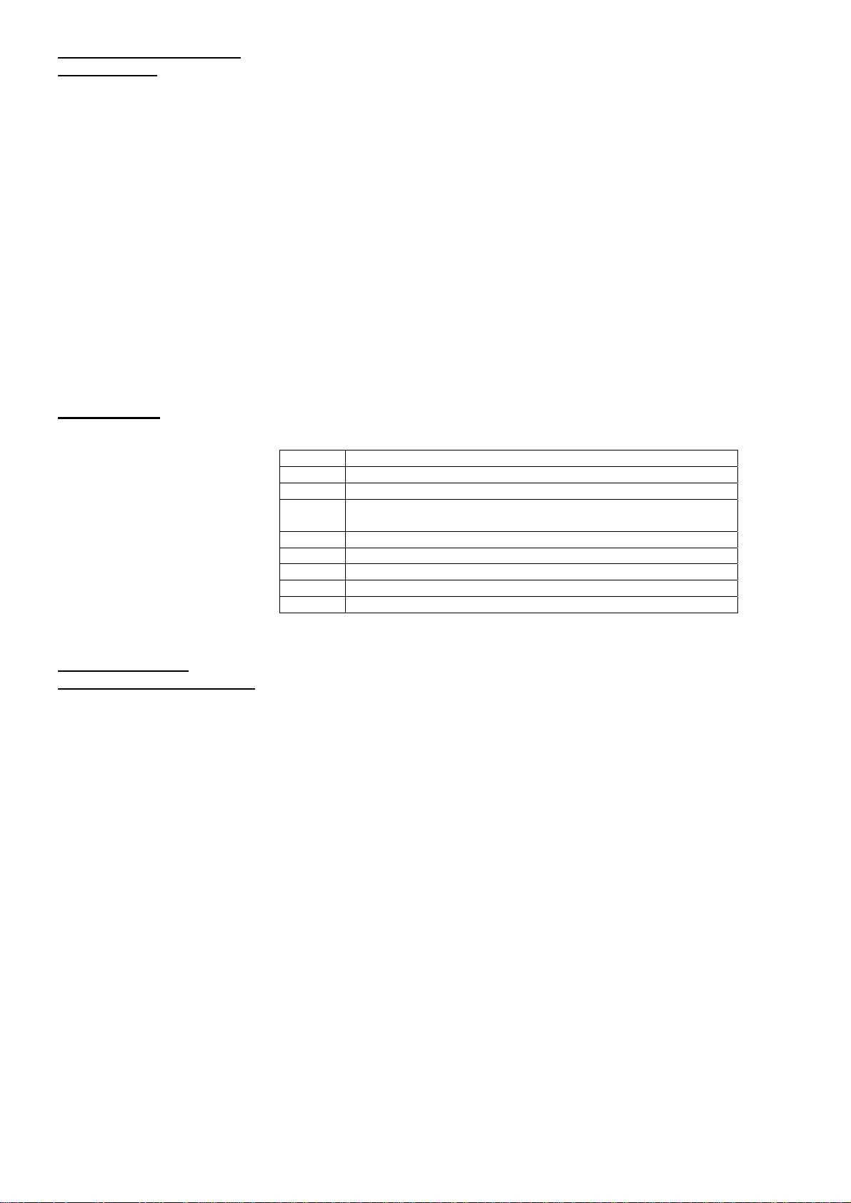
1.Zona cottura a induzione anteriore sinistra
2.Zona cottura a induzione posteriore sinistra
3.Zona cottura a induzione posteriore destra
4.Zona cottura a induzione anteriore destra
5.Unità di comando del piano cottura
Gestione piano cottura
Accensione piano cottura
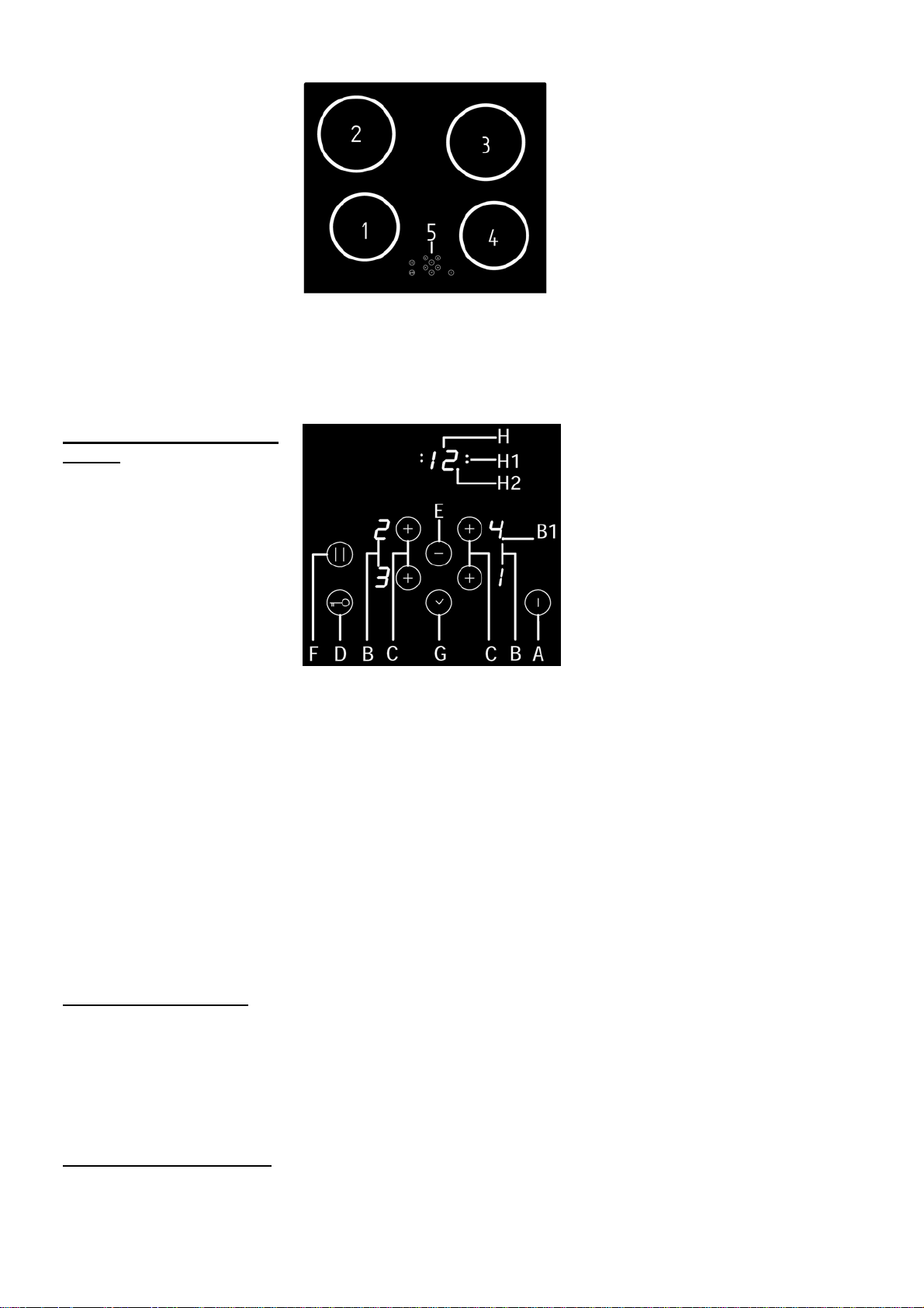
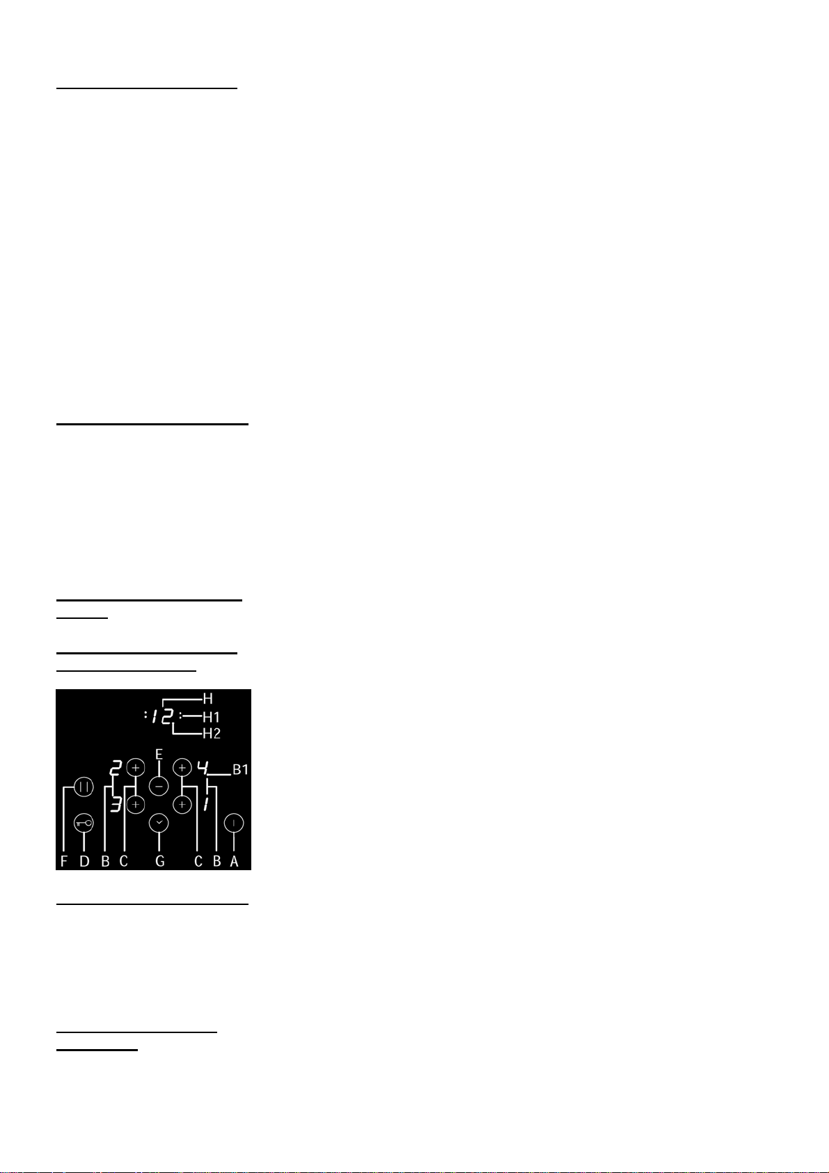
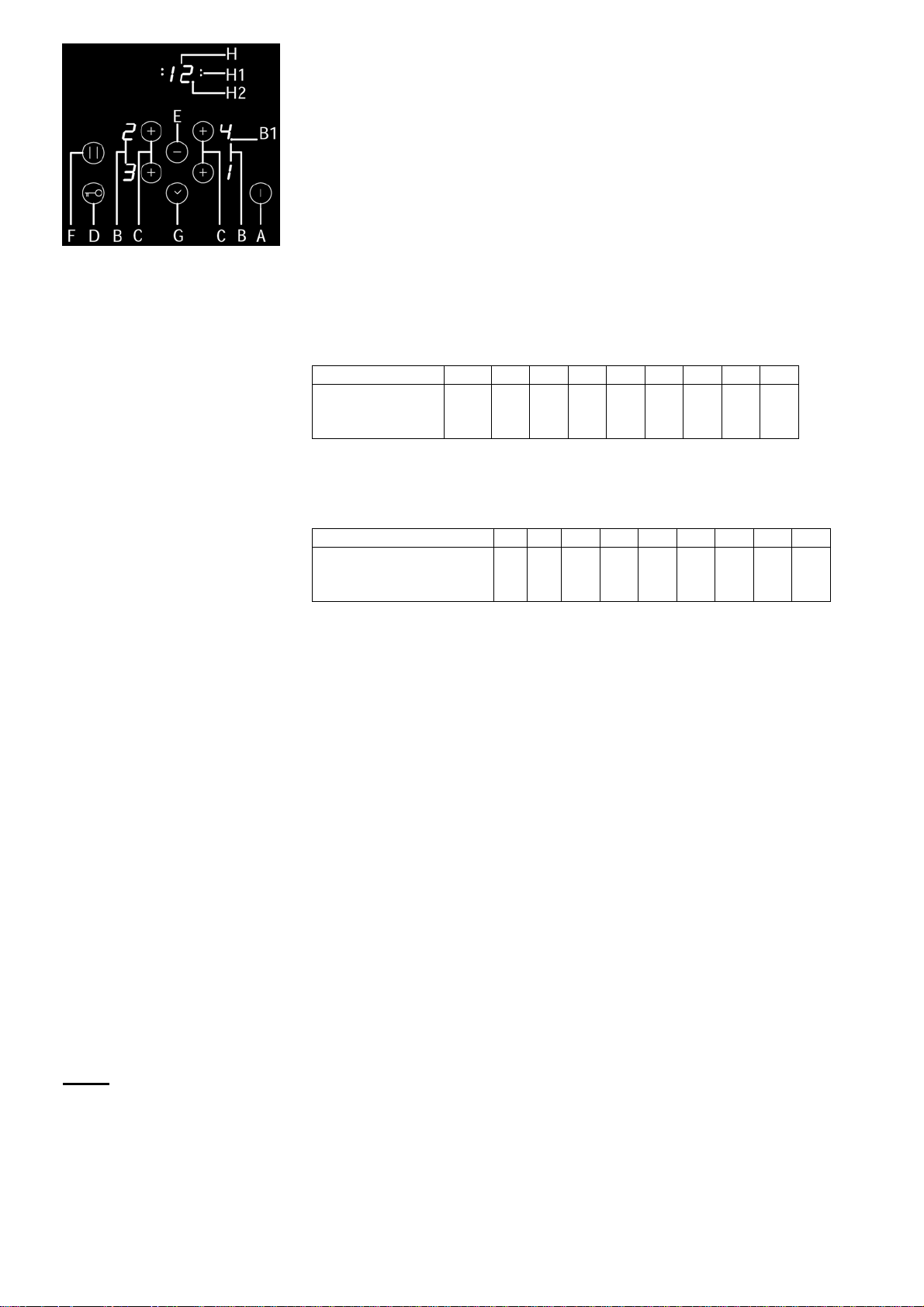
A Sensore per accensione/spegnimento piano cottura
B Indicatori livello cottura o calore residuo
B1 Punto decimale sull’indicatore livello cottura:
- Acceso: possibile gestire zona cottura
- Spento: non è possibile gestire zona cottura
C Sensore per accensione/scelta zona cottura (+)
D Sensore per accensione/spegnimento blocco funzionamento/ Protezione
bambini
E Sensore (-)
F Sensore per accensione/spegnimento pausa
G Sensore per accensione/spegnimento orologio d’accensione, (+)
H Display orologio d’accensione
H1 Spia di controllo per indicare impostazione zona cottura a tempo
H2 Punto decimale sul display dell’orologio:
- Acceso: possibilità di cambiare tempo impostato
- Spento: impossibilità di cambiare tempo impostato
• Al momento dell’accensione del piano cottura in vetroceramica si accendono
tutti gli indicatori (per un attimo). Il piano cottura è pronto per l’uso.
• Il piano cottura è dotato di sensori elettronici che si accendono se toccate le
superfici indicate per almeno 1 secondo.
• Ogni accensione dei sensori è confermata con un segnale acustico.
• Non posizionate gli oggetti sulla superficie dei sensori (Comunicazione di
errori).
• Fate in modo che la superficie dei sensori sia sempre pulita.
Toccare il sensore per accensione/spegnimento (A) per almeno 1 secondo. Il
piano cottura è attivato e su tutti gli indicatori potenza (B) è acceso »0« e
lampeggia il punto decimale (B1).
5
Page 6
Accensione zone cottura
Spegnimento zone cottura
Spegnimento del piano di
cottura
Blocco unità di gestione/
protezione bambini
La prossima impostazione deve essere eseguita in 20 secondi altrimenti il
piano cottura si può spegnere di nuovo.
Se avete acceso il pannello cottura con il sensore per
accensione/spegnimento (A) potete nei prossimi 20 secondi scegliere la zona
cottura desiderata.
• Premendo il sensore (C) per la zona cottura desiderata, il display
corrispondente illumina il livello potenza cottura »0« e il punto decimale (B1) è
illuminato.
• Premendo sensori »+» (C) o »-« (E) impostate il livello di cottura da 1-9.
Tenendo premuto il sensore »+» (C) o »-« (E) i livelli di cottura
diminuiscono o aumentano automaticamente. Questo potete fare anche
toccando singolarmente i sensori corrispondenti e cambiando la potenza
della cottura per un singolo livello ogni volta.
L’impostazione è possibilie solo sulla zona cottura prescelta, vicino alla
quale è illuminato il punto decimale (B1). Sul display è illuminato il simbolo
»0«, o „H“ dipende dalla zona cottura precedentemente
scaldata (vedi capitolo Il calore residuo).
Se spegnete la zona cottura prima della cottura ultimata, potete sfruttare il
calore residuo e così risparmierete l’energia elettrica.
• La zona cottura prescelta deve essere attivata ed il punto decimale (B1)
illuminato.
• Premendo il sensore per l’accensione/spegnimento »-» (E), portate il livello di
cottura a »0« e passati 10 secondi, la zona cottura si spegne.
Spegnimento veloce
• La zona cottura prescelta deve essere attivata ed il punto decimale (B1) è
illuminato.
• La zona cottura si spegne se toccate contemporaneamente i sensori (+) e (-) (C
e E).
• Il pannello cottura può essere spento in qualsiasi momento toccando il sensore
per accensione/spegnimento (A).
L’intero apparecchio può essere bloccato/sbloccato usando il tasto chiave (D), in
modo da prevenire qualsiasi uso involontario. La funzione blocco/sblocco ha anche
funzione di dispositivo per la sicurezza dei bambini.
Una luce spia indica che la funzione di protezione bambini è stata attivata.
Fintanto che la funzione blocco è attiva qualsiasi azione sui tasti non ha nessun
effetto.
Se la funzione di blocco è attiva e, incidentalmente, viene spento il piano, tale
funzione rimarrà ancora attiva nella prossima accensione.
Indicazione calore residuo
Riscaldamento veloce
automatico
Il piano in vetroceramica è dotato dell’indicatore di calore residuo “H”. La zona
cottura non si scalda direttamente, ma attraverso il calore di ritorno trasmesso
dalla pentola. Dopo lo spegnimento della zona, il display mostra il simbolo “H”
illuminato e finchè c’è il calore residuo lo potete usare per riscaldare le pietanze
o scongelare gli alimenti.
Quando il simbolo “H” sparisce, la zona cottura è sempre calda.
Attenzione, pericolo di ustioni!
Tutto il pannello cottura è dotato di un meccanismo particolare che all’inizio di
cottura, senza prendere in considerazione l’impostazione reale del piano cottura,
funziona alla massima potenza. Passato un pò di tempo, quest’ultimo passa
all’impostazione reale di cottura (da 1 a 9). Usando questo meccanismo, bisogna
impostare il livello di cottura che serve per preparare determinato cibo.
6
Page 7
Timer
Accensione riscaldamento veloce, automatico
• La zona cottura scelta deve essere al livello “0”.
• Premendo il sensore (E) il display passa automaticamente al livello cottura 9.
• Finchè il punto decimale è acceso, premete il sensore „+“ (C) della zona cottura
scelta e sul display appare il simbolo „A“.
• Scegliete il livello cottura desiderato. Sul display si alternano le scritte del
simbolo “A“ e il livello di cottura scelto. Passato il tempo di cottura con
riscaldamento veloce, automatico; la zona cottura passa alla cottura del livello
precedentemente scelto, che viene mostrato fisso sul display.
Consiglio
• Se dopo l’accensione del riscaldamento veloce/automatico, non scegliete il
livello di cottura desiderato e quest’ultimo rimane per 3 secondi sul livello 0, il
riscaldamento veloce si spegne automaticamente dopo 10 secondi.
• Se togliete la pentola dalla zona cottura, però in tempo di 5 secondi la rimettete,
il riscaldamento veloce continua fino alla fine.
Livello 1 2 3 4 5 6 7 8 9
Durata
riscaldamento
automatico(min.)
Se avete impostato il riscaldamento veloce, automatico e anche la cottura
particolarmente potente, quest’ultima l’avrà vinta.
Spegnimento di sicurezza
Livello 1 2 3 4 5 6 7 8 9
Ore prima dello
spegnimento di
sicurezza
Il funzionamento ininterrotto alla massima potenza di ogni zona cottura è limitato
nel tempo (vedi tabella sopra). Quando si spegne la zona cottura per il
meccanismo di sicurezza, sul display si illumina il simbolo “0” o “H”, se c’è il
calore residuo.
La zona cottura può essere spenta con il sensore (C) per l’impostazione livello
cottura.
Esempio:
Impostate la zona cottura al livello di cottura 5 e lo lasciate funzionare per un
certo tempo. Se non cambiate il livello
di cottura, il meccanismo di sicurezza dopo 4 ore di funzionamento spegnerà la
cottura.
Apparecchio di sicurezza contro surriscaldamento
La cucina a induzione è dotata di un apparecchio di sicurezza contro il
surriscaldamento, che protegge la parte elettronica dai danni.
L’apprecchio di sicurezza funziona su più livelli.
Quando la temperatura della zona cottura raggiunge livelli molto alti, si attiva per
primo il ventilatore a due livelli. Se questo non dovrebbe bastare, si disattiva
l’impostazione potenza particolarmente forte; così facendo si abbassa il livello di
cottura di alcune zone cottura oppure subentra l’apparecchio di sicurezza contro
il surriscaldamento e lo spegne del tutto.
Quando la superficie si raffredda avete ancora a disposizione tutta la potenza
delle zone cottura.
L’orologio per la cottura a tempo del piano cottura facilita la cottura e può essere
usato anche come avvertitore.
Accensione orologio
• Toccando il sensore per accensione/spegnimento delle zone cottura (C)
scegliete la zona cottura. Il punto decimale s’illumina (B1).
• Con il sensore »+» o »-« (C o E) scegliete il livello cottura da 1-9.
• Toccando il sensore per accensione/spegnimento dell’orologio (G) attivate
l’orologio. Sul display dell’orologio (H) appare il simbolo »00«.
0,8 2,4 3,8 5,2 6,8 2,0 2,8 3,6 0,2
6 6 5 5 4 1.5 1.5 1.5 1.5
7
Page 8
Timer come avvertitore
• Premendo il sensore»+» o »-« (G o E) impostate il tempo di cottura desiderato
(da 01 a 99 minuti). L’orologio inizia a funzionare automaticamente dopo qualche
secondo. La spia di controllo di zona cottura prescelta è illuminata (H1).
Con l’orologio potete impostare il tempo di cottura per ogni zona cottura
contemporaneamente.
Per impostare più velocemente il tempo di cottura tenete premuto in
continuazione il sensore »+» o »-« (G o E).
Cambio tempo cottura con orologio
• Il tempo di cottura può essere cambiato in ogni momento durante il
funzionamento.
• Premendo il sensore per accensione/spegnimento (C) scegliete la zona cottura.
Il punto decimale s’illumina (B1).
• Premendo il sensore per accensione/spegnimento orologio (G) accendete
l’orologio, lampeggia (H1) della zona cottura prescelta.
• Premendo i sensori»+» o »-« (G o E) impostate il tempo nuovo di cottura
desiderato.
Tempo cottura residuo
Tempo di cottura residuo può essere richiamato toccando il sensore per
accensione/spegnimento zone cottura (C).
Spegnimento orologio
Passato il tempo impostato di cottura con l’orologio, si accende il segnale
acustico a intervalli, che può essere spento toccando il sensore adeguato o si
spegne da solo dopo 2 minuti.
Se volete spegnere l’orologio prima del tempo impostato:
• Toccando il sensore per accensione/spegnimento zone cottura (C) attivate la
zona cottura desiderata. Il punto decimale s’illumina (B1).
• Toccate il sensore per accensione/spegnimento orologio (G).
• Toccando il sensore »-» (E) cambiate il tempo cottura a »00«.
Si spegne la funzione della cottura a tempo (l’orologio), mentre la zona cottura
funziona ancora finchè non la spegnete manualmente.
Spegnimento veloce
• Toccando il sensore per accensione/spegnimento zone cottura (C) attivate la
zona cottura desiderata. Il punto decimale s’illumina (B1).
• Toccando contemporaneamente i sensori »+» o »-« (G e E) il timer si spegne.
Sul display dell’orologio (H) appare il simbolo »00«, mentre sul display della zona
cottura appare il livello di cottura impostato.
L’orologio di cottura può essere usato come avvertitore se non lo state già
usando per la cottura a tempo.
Impostazione avvertitore
Se il pannello cottura è spento:
• Premendo il sensore per accensione/spegnimento pannello cottura (A) lo
accendete.
• Premendo il sensore per accensione/spegnimento orologio (G) attivate
l’orologio.
• Premendo il sensore »+« (G) o »-« (E) impostate il tempo desiderato.
Spegnimento avvertitore
Passato il tempo impostato, si accende il segnale acustico a intervalli, che può
essere spento toccando il sensore o si spegne da solo dopo 2 minuti.
Se volete spegnere l’avvertitore prima del tempo impostato:
• Premete il sensore per accensione/spegnimento orologio (G).
• Premendo il sensore »-» (E) , il tempo di cottura si sposta su »00«. L’avvertitore
si spegne.
Premendo contemporaneamente i sensori »+»e »-« (G e E) l’avvertitore si
spegne.
• Finchè è attivo l’avvertitore, l’orologio a tempo non può essere usato per una
zona cottura scelta (bisogna prima disattivare l’avvertitore).
8
Page 9

Funzione pausa
Limitazione della potenza
Procedura di
configurazione
Quando una o più zone di cottura sono attivate, è possible interrompere il
processo di riscaldamento premendo il tasto pausa (F).
Tutti i display di tutte le zone di cottura mostrano il simbolo di pausa “II”.
Tutte le zone di cottura attive smettono di riscaldarsi.
Per uscire dalla modalità pausa, premere di nuovo il tasto di pausa (F) e poi
qualsiasi altro tasto del comando.
La funzione pausa si spegne automaticamente dopo 10 minuti.
Nel caso in cui il piano cottura sia già in funzione da tempo, per cambiare il limite di
potenza, prima di procedere con la programmazione, staccare la spina, quindi
reinserire la spina dopo un paio di minuti.
La potenza predisposta è di 2800W, ma è possibile aumentarla a 5600W.
Impostazione del limite di potenza del piano cottura:
Per impostare il limite di potenza del piano cottura, attuare la seguente procedura:
▪ Il nuovo limite va impostato entro i primi 10 minuti dal collegamento
dell’elettrodomestico alla rete elettrica
▪ Il TC rimane spento (tutti i display rimangono neri)
Accesso al menù di servizio:
▪ Premere contemporaneamente i tasti »-« e »chiave« per almeno 5 secondi
▪ (C) e (1) vengono mostrati a turno sul display “posteriore sinistro”. (1) viene
mostrato sul display “frontale sinistro”.
Accesso alla configurazione per la limitazione di potenza:
▪ Per cambiare l’impostazione (“1”=limitazione potenza, “0”=nessuna limitazione di
potenza) premere il tasto della zona cottura frontale sinistra, il settaggio può essere
modificato con i tasti »-« e il tasto di selezione della zona frontale sinistra.
▪ Per confermare la scelta premere e tenere premuto il tasto On/Off.
Display posteriore sx Display frontale sx Descrizione
C0 0 Inizio configurazione
C1
Preparazione:
▪ Tutte le pentole e le padelle devono essere rimosse dalle zone cottura
▪ Si dovrà avere a disposizione una pentola adatta per l’induzione. La misura di tale
pentola dovrebbe essere minimo l’80% del diametro maggiore dell’elemento
riscaldante.
▪ La configurazione è possibile solo entro 10 minuti dalla connessione alla rete.
▪ Il TC rimane spento (tutti i display rimangono neri).
Accesso al menu di servizio:
▪ Premere insieme il tasto »chiave« e il »-« per almeno 5 secondi.
▪ (C) e (1) vengono mostrati a turno sul display “posteriore sinistro”. (1) viene
mostrato sul display “frontale sinistro”.
Accesso al menù di configurazione:
▪ Premere il tasto della zona di cottura “posteriore sinistra”
▪ Premere il tasto »-«, il display posteriore sinistro” cambia da “1” a “0”.
▪ Premendo il tasto On/Off e tenendolo premuto si entra nel processo di
configurazione.
Processo di configurazione:
▪ Dopo l’ingresso nel menù di configurazione : “C” sta ad indicare le zone di cottura
configurate e “-“ per le zone già configurate.
▪ Bisogna posizionare una pentola sulle zone di cottura da configurare; poi premere
il tasto della zona di cottura. (assegnazione della zona di cottura alla sua posizione
→memorizzato nel software dell’elemento riscaldante).
▪ Le zone di cottura già configurate non possono essere configurate di nuovo senza
cancellare la configurazione precedente.
Note importanti:
▪ Non più di una pentola deve essere posizionata sul piano durante il processo di
configurazione.
▪ In caso di una configurazione errata, l’intera configurazione deve essere cancellata
prima di configurare nuovamente le zone.
▪ Nel caso in cui due o più elementi riscaldanti abbiano la stessa configurazione, il TC
0 Nessuna limitazione potenza
1 Limitazione potenza
9
Page 10

lo rileva e viene mostrato “E4”. L’intera configurazione deve essere cancellata.
▪ In caso di una configurazione annullata non si deve effettuare nessun intervento
entro i prossimi 5 secondi → gli elementi riscaldanti ad induzione dovrebbero
essere ripristinati.
Funzioni di sicurezza e segnalazione errori.
ERRORE DESCRIZIONE ERRORE ELIMINAZIONE
ER03 + SUONO CONTINUO Attivazione continua dei sensori (TASTI)
per più di 10 secondi, causata dalla
presenza di oggetti o liquidi sul vetro nella
zona del touch control
ER21 Questo messaggio appare al termine del
ciclo di controllo della eventuale sovratemperatura del vano del touch control.
U400 Tensione al secondario troppo alta (tens al
primario > 300V). Il touch si spegne dopo
1 secondo ed emette un segnale acustico
continuo. Questo può essere dovuto a :
1)fornitura di tensione elevata 2)Errore di
connessione del piano cottura alla rete di
alimentazione
ER22 ANOMALIA DELLA SCHEDA DI
COMANDO , RIGUARDANTE I SENSORI
DI SELEZIONE oppure TENSIONE DI
ALIMENTAZIONE DEL TOUCH AL DI
FUORI DEL RANGE CONSENTITO.
ER36 CORTO CIRCUITO NEL SENSORE DI
TEMPERATURA DEL TOUCH CONTROL
ER20 Anomalia della memoria del
microcontroller
ER40 Tensione secondaria del touch troppo
basso e temperatura PTC del primario
troppo alta
E4 Il messaggio compare nella zona di cottura
non configurata
ER47 Comunicazione anomala tra touch control
e uno o più moduli induzione.
ER31 Anomalia nella configurazione dei moduli
induzione
E2 Sovra-temperatura nelle bobine di uno o
più moduli induzione , per uso scorretto
del piano cottura o per guasto della
ventola di raffreddamento.
E5 Anomalia del filtro della scheda di potenza CONTATTARE IL CENTRO DI
E6 Anomalia della scheda di potenza CONTATTARE IL CENTRO DI
Se il problema persiste ,
CONTATTARE IL CENTRO DI
ASSISTENZA TECNICA
AUTORIZZATO – SPECIFICANDO IL
CODICE DI ERRORE
CONTATTARE IL CENTRO DI
ASSISTENZA TECNICA
AUTORIZZATO – SPECIFICANDO IL
CODICE DI ERRORE
1)CONTATTARE IL CENTRO DI
ASSISTENZA TECNICA
AUTORIZZATO – SPECIFICANDO IL
CODICE DI ERRORE 2)Contattare
un elettricista per verificare la rete
domestica
CONTATTARE IL CENTRO DI
ASSISTENZA TECNICA
AUTORIZZATO – SPECIFICANDO IL
CODICE DI ERRORE
CONTATTARE IL CENTRO DI
ASSISTENZA TECNICA
AUTORIZZATO – SPECIFICANDO IL
CODICE DI ERRORE
CONTATTARE IL CENTRO DI
ASSISTENZA TECNICA
AUTORIZZATO – SPECIFICANDO IL
CODICE DI ERRORE
CONTATTARE IL CENTRO DI
ASSISTENZA TECNICA
AUTORIZZATO – SPECIFICANDO IL
CODICE DI ERRORE
CONTATTARE IL CENTRO DI
ASSISTENZA TECNICA
AUTORIZZATO – SPECIFICANDO IL
CODICE DI ERRORE
CONTATTARE IL CENTRO DI
ASSISTENZA TECNICA
AUTORIZZATO – SPECIFICANDO IL
CODICE DI ERRORE
CONTATTARE IL CENTRO DI
ASSISTENZA TECNICA
AUTORIZZATO – SPECIFICANDO IL
CODICE DI ERRORE
CONTATTARE IL CENTRO DI
ASSISTENZA TECNICA
AUTORIZZATO – SPECIFICANDO IL
CODICE DI ERRORE
ASSISTENZA TECNICA
AUTORIZZATO – SPECIFICANDO IL
CODICE DI ERRORE
ASSISTENZA TECNICA
AUTORIZZATO – SPECIFICANDO IL
CODICE DI ERRORE
10
Page 11

E9 Difetto del sensore di temperatura di un
modulo induzione
CONTATTARE IL CENTRO DI
ASSISTENZA TECNICA
AUTORIZZATO – SPECIFICANDO IL
CODICE DI ERRORE
PULIZIA E MANUTENZIONE PIANO COTTURA
La superficie in vetroceramica deve essere pulita dopo ogni utilizzo, poichè ogni
piccola macchia che rimane si brucerà sulla superficie calda.
Per la manutenzione ordinaria usate detersivi speciali che formano una specie di
pellicola protettiva dallo sporco.
Prima di ogni utilizzo della superficie in vetroceramica bisogna togliere la polvere
dalla superficie e possibile sporcizia dal fondo delle pentole, che potrebbe
graffiare le zone cottura (Fig.1).
Fig.1
Fig.2
Fig.3
Fig.4
Fig.5
Attenzione: non usate le spugne d’acciaio o i detersivi abrasivi che possono
graffiare la superficie. Altrettanto si può danneggiare usando spray aggressivi o
detersivi non adeguati (Fig.1 e Fig.2).
La segnaletica si può consumare per l’uso dei detersivi aggressivi, spugne
d’acciaio o i fondi delle pentole sporchi (Fig.2). La sporcizia più piccola può
essere eliminata con una spugna umida e poi la pentola asciugata per bene
(Fig.3).
Le macchie d’acqua si possono eliminare con la soluzione di aceto, con la quale
però non potete passare sulla cornice (di alcuni modelli) perchè può perdere la
sua brillantezza. Non dovete usare detersivi e spray aggressivi per eliminare il
calcare (Fig.3).
La sporcizia più ostinata si elimina con detersivi specifici per la pulizia delle
superfici in vetroceramica. Seguite i consigli del produttore del detersivo.
Attenzione a togliere completamente il detersivo dalla superficie poichè qualche
residuo potrebbe danneggiare la superficie in vetroceramica (Fig.3).
La sporcizia più ostinata o bruciata va tolta con il raschietto. Fate attenzione che
la maniglia in plastica del raschietto, non venga in contatto con il piano cottura
caldo (Fig.4).
Fate attenzione a non farvi male quando usate il raschietto! Lo zucchero o le
pietanze che contengono tanto zucchero possono danneggiare per sempre la
superficie in vetroceramica (Fig.5), per questo bisogna immediatamente
eliminare con il raschietto i residui di zucchero dalla superficie in vetroceramica
anche se è ancora calda (Fig.4).
Cambio di colore della superficie in vetroceramica non influisce sul
funzionamento o sulla stabilità della superficie. Quest’ultima è conseguenza di
utilizzo delle pentole in rame o in alluminio o i residui del cibo sul fondo della
pentola, che però è molto difficile eliminare.
Avvertenza:Tutti gli errori sopra indicati sono di carattere estetico e non
influenzano direttamente sul funzionamento dell’apparecchio. Essi non possono
essere eliminati in garanzia.
11
Page 12

INCASSO PIANO COTTURA
Avvertenze importanti
• L’incasso dell’apparecchio e il collegamento alla rete elettrica può essere eseguito solamente da personale qualificato.
• Il rivestimento delle pareti dell’apparecchio da incasso deve essere trattato con le colle resistenti a 100°C (se non resiste
a temperature così alte potrebbe cambiare forma e colore).
• L’apparecchio può essere incassato sul piano di lavoro dove la larghezza del mobile supera 600mm.
• Dopo il montaggio, l’apparecchio da incasso deve avere libero accesso ai due elementi fissati, partendo dalla parte
inferiore.
• Tutti i mobili appesi della cucina devono essere posizionati su altezze che non disturbino i processi di lavoro.
• La distanza tra il piano cottura e la cappa deve rispettare le indicazioni per il montaggio della cappa. La distanza minima
è di 700mm.
• Sul piano di lavoro si possono mettere le cornici di legno massiccio purchè si rispetti la distanza minima (vedi il disegno).
• La distanza minima tra pannello con il piano cottura e la parete posteriore è segnalata sul disegno.
Misure del taglio pannello
cottura a induzione a
580mm
incasso
A
B
C
D
E
F
G
H
510mm
560mm
490mm
50mm
10mm
50mm
5mm
Procedimento dell’incasso
▪ Il piano cottura può essere incassato solo nel piano lavoro di spessore fra 25 e
40mm.
▪ L’elemento inferiore della cucina non deve avere il cassetto. Deve essere dotato di
sbarra orizzontale che deve essere distante 20mm dalla superficie di lavoro
inferiore. Lo spazio tra la sbarra e il piano cottura deve rimanere vuoto.
▪ Nella parte posteriore del mobile ci deve essere il taglio di altezza minima di
50mm, su tutta la larghezza del mobile.
▪ L’incasso del forno sotto il pannello cottura è possibile con i forni con ventilatore
raffreddante.
Prima di installare il forno bisogna eliminare nell’area di apertura la parete
posteriore del mobile.
Altrettanto deve esserci l’apertura minima di 5mm nella parte anteriore.
▪ Il piano di lavoro deve essere completamente diritto.
▪ Proteggere le superfici tagliate.
▪ Collegare il piano cottura alla rete di alimentazione (guardare le istruzioni per il
collegamento).
▪ Posizionare il piano cottura sull’apertura precedentemente tagliata.
▪ Spingere con forza contro il piano di lavoro.
12
Page 13

COLLEGAMENTO ALLA RETE ELETTRICA
Adattamento di base dei
sensori all’ambiente
Schema di collegamento
▪ Il collegamento elettrico può essere eseguito solo da personale qualificato. La
protezione del collegamento elettrico deve rispettare le norme in vigore.
▪ I connettori di collegamento sono a portata quando aprite il coperchio dei
conduttori.
▪ Prima del collegamento bisogna verificare che la tensione scritta sulla targhetta
corrisponda alla tensione della rete elettrica.
▪ La targhetta del piano in vetroceramica si trova nella parte inferiore
dell’apparecchio.
▪ L’apparecchio funziona se è collegato alla corrente alternata 220-240V ~.
▪ Nel collegamento diretto alla rete è interposto tra l’apparecchiatura e la rete stessa
un interruttore omnipolare con apertura minima tra i contatti di 3mm, dimensionato
al carico e rispondente alle norme in vigore. Sono consigliabili interruttori LS o
valvole limitatrici.
▪ Il collegamento deve essere scelto secondo la possibilità di installazione della
corrente elettrica e delle valvole limitatrici.
▪ Per la sicurezza contro incendio, gli apparecchi di questo tipo possono essere
incassati fra un mobile più alto di esso e dall’altra parte contro il mobile della stessa
altezza dell’apparecchio.
▪ Parti di collegamento elettrico, e parti isolate, devono essere protette dalla
possibilità di essere toccate.
Dopo ogni collegamento alla rete elettrica si esegue automaticamente l’adattamento
di base che assicura la funzione ottimale dei sensori. Tutti i display si accendono per
alcuni secondi. Durante l’adattamento dei sensori non ci devono essere alcuni
oggetti. Se non è così, l’adattamento si interrompe finchè non togliete gli oggetti.
Durante questo tempo non potete usare il pannello cottura.
ATTENZIONE!
Prima di ogni intervento staccare l’apparecchio dalla rete elettrica. L’apparecchio
deve essere collegato, secondo la tensione di rete, seguendo lo schema. Il
conduttore di protezione (PE) deve essere collegato al fermaglio di messa a terra .
Il cavo di collegamento deve passare attraverso la staffa che lo protegge da
movimenti accidentali.
Dopo il collegamento accendere tutte le zone cottura per almeno 3 minuti per
verificare il loro funzionamento.
Per il collegamento si devono usare:
• cavi ricoperti di gomma tipo HO5RR-F con fili di colore giallo/verde,
• cavi ricoperti di gomma tipo HO7RN-F con fili di colore giallo/verde.
13
Page 14

CARATTERISTICHE TECNICHE
Tipo FHBP 604 4I T B2 XS
Larghezza
Tensione nominale
Tipo interruttori
Zone di cottura ( Ø, mm/W )
Davanti a sinistra
Dietro a sinistra
Dietro a destra
Davanti a destra
Potenza totale (W)
580 mm
220-240 V~ or 380-415 V 2N~, 50/60 Hz
Sensori elettronici
160 , 1400
180 , 1400
180 , 1400
160 , 1400
2800 - 5600
14
Page 15

Dear customer!
Instruction for use
Installation instruction
Rating plate
Fire hazard protection
The built-in ceramic-glass cooktop is intended for household use only. Materials
used for packaging are nature friendly and may be recycled, deposited or
destroyed without any threats to the environment. In order to recognize these
features, all packing materials are marked with relevant symbols.
Once your appliance has become obsolete and you do not intend to use it any
longer, take adequate care not to litter the environment. Deposit your old
appliance with the authorized depot dealing with used household appliances.
Instructions for use have been prepared for the user, anddescribe the particulars
and handling of the appliance. These instructions apply to different models from
the same family of appliances, therefore you may fi nd information and
descriptions that may not apply to your particular appliance.
The appliance should be connected to the power supply in accordance with the
instructions from the chapter “Electrical connections” and in line with the standing
regulations and standards. The connections should be carried out by a qualified
personnel only.
The rating plate with basic information is located underneath the appliance.
Appliances are allowed to be mounted on one side next to a high kitchen cabinet,
the height of which may exceed that of the appliance. On the opposite side
however, only a kitchen cabinet of equal height as the appliance is allowed.
Important warnings 16
Ceramic-glass cooktop 19
Hob control 19
Power limitation 22
Configuration procedure 23
Safety functions and error display 24
Cleaning and maintenance of ceramic-glass hob 25
Mounting the built-in cooktop 26
Connection to the power supply 27
Tecnical information 28
15
Page 16

IMPORTANT WARNINGS
• The appliance may be built-in and connected to the power supply only by a
qualified technician.
• Particular areas of the cooktop surface (adjacent to the hotplates) are hot
during operation.
Prevent the children to hang around the appliance and warn them properly
against the danger of burns.
• Hot oil ignites readily, so be sure have the preparation of such food (fries) under
constant control.
• Hotplates may not be left in operation empty, without any dishes on top.
• Never use the appliance for heating the ambience.
• Never use the ceramic-glass cooktop as a working surface. Sharp objects may
damage the cooktop surface.
• Never place any metal objects upon the induction hotplate, such as knives,
forks, spoons, pot lids, and the like, as they may get very hot.
• Preparation of food in aluminium or plastic cookware is not allowed. Never
place any plastic objects or aluminium foil upon the cooktop surface.
• In case any other appliances are plugged in the electric mains close to the
cooktop, prevent the contact of the plug cable with the hot cooking zones.
• Never keep any flammable or temperature sensitive objects, like cleaning
agents, sprays, detergents, etc., below the appliance.
• Never use cracked or broken ceramic-glass cooktop. In case you notice any
visible cracks on the surface, cut the power supply immediately.
• In case of any malfunctions, disconnect the appliance from the power supply
and call service department.
• Do not use high-pressure steam cleaner or hot steam to clean the appliance.
• The appliance is manufactured in compliance with the relevant effective safety
standards.
Nevertheless, we strongly recommend that persons with impaired physical,
motorial, or mental capacity, or persons with inadequate experience or
knowledge, do not use the appliance unless attended by a qualifi ed person. The
same recommendation applies when the appliance
is used by persons of less-than-legal age.
The symbol on the product or on its packaging indicates that this product
may not be treated as household waste. Instead it shall be handed over to
the applicable
collection point for the recycling of electrical and electronic equipment. By
ensuring this product is disposed of correctly, you will help prevent
potential negative
consequences for the environment and human health, which could
otherwise be caused by inappropriate waste handling of this product. For
more detailed information about recycling of this product, please contact
your local city office, your household waste disposal service or the shop
where you purchased the product.
16
Page 17

Hotplate function principle
Appropriate cookware for
induction hotplates
• Ceramic glass hob is fitted with three or four hotplates. Hob surface is
completely flat and smooth, without edges to accumulate dirt.
• The hob is fi tted with high power induction hotplates. Heat is generated directly
at the bottom of the dish, where it is most needed, without any losses through the
ceramic glass surface.
This way the required extent of energy is considerably smaller compared to
traditional heaters, which operate on radiation principle.
• Glass ceramic hotplate is not heated directly, but only by return heat
transmitted by the dish. This heat figures as “remaining heat” after the hotplate is
turned off. The induction hotplate generates heat from the induction coil, installed
underneath the ceramic glass surface. The coil creates magnetic field at the
bottom of the dish (which can me magnetized) which in turn originates whirling fl
ows of current which then heat the hotplate.
IMPORTANT!
In case sugar or other heavily sweetened substance is spilled on the hotplate,
wipe it immediately and remove the sugar residues with a scraper although the
cooking zone is still hot, otherwise the hotplate may be damaged.
Avoid cleaning the cooktop while the cooking zones are still hot, as you may
damage the hob.
• Induction hotplate will function perfectly only if appropriate cookware is used.
• Dish should be in the middle of the hotplate during cooking.
• The appropriate cookware is the one which enables induction, for example
steel, enamel or steel alloy cookware. Pots made from steel alloy with copper or
aluminium bottom, or glass pots are inappropriate.
• If you use the pressure cooker (“economy pot”) keep it under close surveillance
until proper pressure is obtained. Hotplate should fi rst operate on maximum
power, then follow the manufacturer’s instructions and use the appropriate
sensor to decrease the power.
• When buying cookware, check if it bears the label “allows induction”.
Cooking zones Min. pan bottom Ø Max. pan bottom Ø
Ø 160 mm Ø 110 mm Ø 160 mm
Ø 180 mm Ø 110 mm Ø 180 mm
Power regulation
Magnet test
Use small magnet to test if the dish bottom is magnetic. Only dishes where
magnet sticks to the bottom are suitable for induction cooking.
Dish recognition
One of great advantages of the induction hotplate is dish recognition. Even if
there are no dishes upon the hotplate, or the dish diameter is smaller than the
diameter of the relevant hotplate, there are no thermal energy losses. When the
hotplate is on, the power indicator displays letter “U”. If you place the dish over
that hotplate within the following 10 minutes, the hotplate recognizes the dish
and turns on to the preset power value.
At the moment you remove the dish from the hotplate, power is suspended. If
you place smaller dish upon the hotplate and it is recognized, the hotplate will
only use the amount of energy required to heat the dish according to its size.
Hotplate may be damaged if:
• it is turned on and left empty, or an empty dish is placed on it;
• you use clay dishes which leave scratches on the ceramic glass surface;
• you fail to wipe the dish bottom dry prior placing it on the ceramic glass
hotplate; heat induction is obstructed and the hotplate may be damaged;
• you fail to use the appropriate dishes that can be magnetized: steel dishes,
enamel or steel alloy dishes; induction hotplate will not function otherwise.
Heating power of the hotplates may be set at nine different levels.
The following chart indicates illustrative use of each power setting.
17
Page 18

ENERGY SAVING TIPS
Power
Setting
1-2
4-5
7-8
A
• When buying cookware be careful in selecting size: pot diameter usually refers
to the top edge of the dish, which is often larger than the dish bottom.
• Steam-pressure pots (economic pots), which use pressure in tightly sealed
interior, are especially economic, and save both time and energy. Shorter
cooking time leaves more vitamins in food.
• Always leave enough water in steam-pressure pots, otherwise it may result in
overheating which may damage both the pot and the hotplate.
• Always cover the cookware with lids of appropriate size.
• Use such dish size to accommodate the quantity of food to be prepared. If you
use excessively large pot for small amount of food, you will consume
considerably more energy.
Purpose
Off, using remaining heat
0
Maintaining warm food, slow simmer of smaller quantities
Slow simmer (continuation of cooking after a powerful start-up)
3
Slow cooking (continuation) of larger quantities, roasting larger
chunks
Roasting, browning
6
Roasting
Start of cooking, roasting
9
Automatic initial setting
18
Page 19

CERAMIC-GLASS COOKTOP
Hob control elements
Hob control
Activating the hob
1.Induction hotplate front left
2.Induction hotplate rear left
3.Induction hotplate rear right
4.Induction hotplate front right
5.Hob control panel
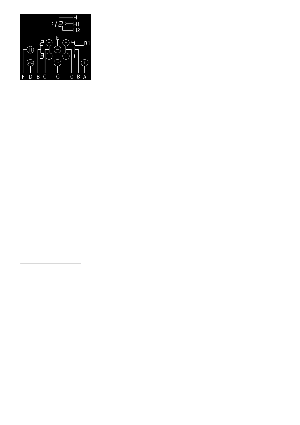
A ON/OFF sensor
B Hotplate power or remaining heat displays
B1 Decimal dot on the power displays:
- On: hotplate power control is possible
- Off: hotplate power control is not possible
C Hotplate selection and ON/OFF sensors (+)
D Child lock ON/OFF sensor
E Sensor (-)
F Pause function
G Timer ON/OFF sensor, (+)
H Timer display
H1 Timer controlled hotplate signal lamp
H2 Decimal dot on clock display:
- On: time setting is possible
- Off: time setting is not possible
• After turning the ceramic glass hob on all displays come on for a moment. The
hob is ready for operation.
• The hob is fitted with electronic sensors which are switched on if you touch the
relevant circle for at least one second.
• Each sensor activation is followed by a sound signal.
• Avoid placing any objects on sensor surface (possible error signalization).
Always keep the sensor surface clean.
Touch the ON/OFF sensor (A) for at least one second. The hob is now active,
and all hotplate power indicators (B) indicate »0«, decimal dot (B1) is flashing.
Now you need to select the next setting within 20 seconds, otherwise the
hob switches off again.
19
Page 20

Turning hotplates on
Switching hotplates off
Switching the hob off
Locking the control unit /
child safety lock
After turning the hob on using the ON/OFF sensor (A), within the next 20
seconds start one of the hotplates.
• Touching the desired hotplate sensor (C), its relevant power indicator indicates
»0« and decimal dot (B1) is on.
• By touching sensors »+» (C) or »-« (E) set the desired cooking
power from 1 to 9.
Continuous pressing of »+» (C) or »-« (E) sensors the power level is
automatically increased or reduced. Another procedure is to change power
in steps is by intermediate touching of relevant sensors.
Setting is always possible for one hotplate only at the time - the one with
the decimal dot on (B1). Power display indicates »0«, or „H“, depending on
the existing temperature of the hotplate (see Section
Remaining Heat Indicator).
You can also turn the hotplate off prior the end of cooking and use the
remaining heat, and save energy.
• Selected hotplate must be activated, decimal dot (B1) is on.
• Touching the hotplate sensor »-» (E) set the power level to »0«. After 10
seconds the hotplate is turned off.
Fast deactivation
• Selected hotplate must be activated, decimal dot (B1) is on.
• Press both (+) and (-) (C and E) sensors simultaneously, and the hotplate is
immediately switched off.
• The hob can be switched off any time by pressing the ON/OFF sensor (A).
The whole appliance can be locked/unlocked using the safety lock key (D), in order to
prevent any unintentional use. The function also serves as a child safety device. A
pilot light indicates that the safety lock function has been enabled.
As long as the safety lock function is enabled, any action on the keys has no effect.
If the safety lock function is active and, accidentally, the hob is turned off, that
function
will still be enabled when the cook top is turned on again.
Remaining heat indicator
Automatic fast heating
Glass ceramic hob also features remaining heat indicator “H”. Hotplates are not
heated directly, but through return heat radiating from the dish. As long as the
symbol “H” is on after the hotplate was switched off, the remaining heat may be
used for warming up food or for melting.
Even when the symbol “H” disappears, the hotplate may still be hot.
Be careful of burns!
The entire hob is fitted with special mechanism which makes the hotplates
operate at full power at the beginning of cooking, regardless of the selected
setting. After certain time the power of the hotplate returns to the originally set
value (1 to 9).
In using this mechanism it is only necessary to select the appropriate power level
for the intended preparation of food, which is to be used during that particular
cooking session.
Activation of automatic fast heating
• Selected hotplate must be set to level “0”.
• Touch the sensor “E” and the display switches to the power setting 9.
• As long as the decimal dot (B1) is on, press the sensor “+” (C) of the relevant
20
Page 21

Timer
hotplate and the display indicates letter “A”.
• Select desired power level. Power indicator intermittently displays the “A”
symbol and the selected power setting. When the fast heating period expires,
hotplate switches to the pre-selected power setting, displayed
constantly on the indicator.
Hint
• If the power selection knob remains at level 0 three seconds after the automatic
fast heating is activated, that is if you fail to select the power setting for regular
cooking, the fast heating function is switched off.
• If you remove the dish from the hotplate and then within the next 5 seconds
return it on the hotplate, the fast heating function will resume operating fully to
the end.
Power setting 1 2 3 4 5 6 7 8 9
Maximum
power
cooking time
(min.)
If you activated the automatic fast heating function and also switched on
extra powerful heating, the latter will prevail over the automatic setting.
Safety switch off
Power setting 1 2 3 4 5 6 7 8 9
Hours lapse prior safety
switch off
Maximum continuous operation of a particular hotplate is limited, and the
duration is displayed in the above chart. When the hotplate is switched off by the
safety mechanism, the indicator displays symbols “0”, or “H” in case there is any
remaining heat left.
In such cases switch the hotplate off by touching the relevant power setting
sensor (C).
Example:
Set the hotplate to power level 5 and leave it operate for some time. If you do not
change the above setting, the safety mechanism will switch the hotplate off after
4 hour.
Protection from overheating
Induction hotplate is also fitted with safety device against overheating which
protects electronic parts from damages. This device operates on several levels.
When temperature of the hotplate excessively rises, it switches on two-stage fan.
If this is not enough, extra powerful heating is deactivated, and finally the safety
device either reduces the heating power of certain hotplates or turns them off
completely. When the hotplate cools
off, the full power of hotplate is again available.
Timer facilitates the cooking procedure by setting the period of hotplate
operation, and it can also be used as alarm timer.
Activating the timer
• Touch the hotplate ON/OFF sensor (C) of the relevant hotplate. Decimal dot
(B1) is on.
• By touching the »+» or »-« (C or E) sensor select the power setting from 1 to 9.
• Touch the timer ON/OFF sensor (G) to activate timer. Timer display (H)
indicates »00«.
• By touching sensors »+» or »-« (G or E) set the desired cooking time (from 01
to 99 minutes). After a few seconds timer starts operating. Timer controlled
hotplate control lamp (H1) is on.
You can use timer to set exact cooking time for each hotplate at the same
time. To speed up the timer setting keep the relevant sensors »+» or »-« (G
or E) constantly pressed.
0,8 2,4 3,8 5,2 6,8 2,0 2,8 3,6 0,2
6 6 5 5 4 1.5 1.5 1.5 1.5
21
Page 22

Alarm timer function
The pause function
Power Limitation
Altering preset cooking time
• You can change preset cooking time whenever you wish during the hotplate
operation.
• Touch the hotplate ON/OFF sensor (C) to select the desired hotplate. Decimal
dot (B1) is on.
• Touch the timer ON/OFF sensor (G) to activate the timer. Display (H1) of the
selected hotplate is fl ashing.
• By touching sensors »+» or »-« (G or E) set the new desired cooking time.
Remaining cooking time
You can display the remaining cooking time by touching the hotplate ON/OFF
sensor (C).
Switching the timer off
When the preset time expires a beep is heard which you can either turn off by
touching any sensor or leave it to turn off automatically after 2 minutes.
Switching the timer of prior expiry of preset time:
• Touch the hotplate ON/OFF sensor (C) to select the desired hotplate. Decimal
dot (B1) is on.
• Touch the timer ON/OFF sensor (G).
• By touching the sensor »-» (E) set cooking time to »00«. Timer function is off,
but the hotplate continues to operate until you switch it off manually.
Fast switch off
• Touch the hotplate ON/OFF sensor (C) to select the desired hotplate. Decimal
dot (B1) is on.
• Simultaneously touch both »+» and »-« (G and E) sensors and switch the timer
off. Timer display (H) indicates »00«, and the hotplate indicator displays the
preset power setting level.
Timer can be used as alarm only if it is not already employed in timer control of
one of the hotplates.
Timer setting
With the hob off:
• Touch the hob ON/OFF sensor (A) to activate the cooking hob.
• Touch the timer ON/OFF sensor (G) to activate the timer.
• By touching sensors »+» (G) or »-« (E) set the desired time.
Switching the alarm off
When the preset time expires a beep is heard which you can either turn off by
touching any sensor or leave it to turn off automatically after 2 minutes.
If you want to switch the timer off prior expiry of preset time:
• Touch the timer ON/OFF sensor (G).
• By touching the sensor »-» (E) set cooking time to »00«. Alarm function is off.
Simultaneously touch both »+» and »-« (G and E) sensors and switch the timer
off.
• During the time the alarm is activated, timer can not be preset for any hotplate
(to enable timer setting function, alarm must be switched off).
When one or more cooking zones are activated, it is possible to interrupt the
heating process by pressing the pause button (F).
All displays of cooking zones show the pause symbol “II”.
Any active cooking zone will stop heating.
To exit pause mode, press the pause button (F)again and then any of the touch
sensitive indicators on the hob.
The pause function will switch off automatically after 10 minutes.
In cases where the cooktop is already in operation for some time, to change the limit
of power, before proceeding with the planning, unplug it, then reinsert the plug after a
couple of minutes.
The power drawn is 2800 W, but you can increase it at 5600 W.
Preparation:
▪ Configuration is only possible within 10minutes after connecting to the mains.
▪ TC remains switched off (all displays remain black).
22
Page 23

Configuration Procedure:
Entering the Sercice Menu:
▪ Press together “KeyLock” and “Minus” -> keep it pressed for 5 seconds.
▪ [C] and [1] are displayed in turns on Display “back left”. [1] is displayed on
Display “front left”.
Entering Service Menu Point for Configuration:
▪ Press Cooking Zone Key “Front Left” to switch between “1” and “0”.
▪ Save actual status by pressing the On/Off Key and keep it pressed.
Display “Back Left” Display “Front Left” Description
C0 0 Start configuration
C1
Preparation:
▪ All pots and pans must be removed from the cooking zones.
▪ A pan suitable for induction systems should be available. The size of this pan
should be minimum 80% of the largest IHE diameter.
▪ Configuration is only possible within 10minutes after connecting to the mains.
▪ TC remains switched off (all displays remain black).
Entering the Sercice Menu:
▪ Press together “KeyLock” and “Minus” -> keep it pressed for 5 seconds.
▪ [C] and [1] are displayed in turns on Display “back left”. [1] is displayed on
Display “front left”.
Entering Service Menu Point for Configuration:
▪ Press Cooking Zone Key “Back Left”.
▪ Press Minus Key. Display “Back Left” changes from “1” to “0”.
▪ Start Configuration Process by pressing the On/Off Key and keep it pressed.
Configuration Process:
▪ After successful entry to the configuration menu: “C“ for non-configured
cooking zones and „-„ for already configured comes up.
▪ A pan must be placed on the cooking zones to be configured; then a cooking
zone key must be actuated.(allocation of the IHE to ist position -> stored in IHE
SW).
▪ Already configured cooking zones may not be configured again without
deleting before.
Important notes:
▪ Not more than one single pot may be placed on the hob during configuration
process.
▪ In case of a faulty configuration all configurations in the system must be
deleted before starting again.
▪ In case of two or more IHEs with the same configuration in one hob the TC
detects this in most of the cases and“E4” is displayed. If such a problem is not
detected automatically configuration is not possible. System configuration must
be erased.
▪ In case of an aborted configuration status should not be changed within next 5
sec. -> active IHEs may be reseted.
0 No power limitation
1 Power limitation
23
Page 24

Safety functions and error display.
ERROR CODE ERROR DESCRIPTION INSTRUCTION MANUAL
ER03 &
permanent
tone
ER21 Control unit cuts off after controlling due to
U400 Secondary voltage of the power unit to high
ER22 Key evaluation defective. Control unit cuts off after
ER36 NTC value is not within its specification (value <
ER20 Flash-failure. Microcontroller faulty CONTACT AUTHORIZED CENTER
ER40 Secondary operational voltage min.5 s too low
E4 The message appears in the cooking zone not
ER47 Communication error between TC and induction. CONTACT AUTHORIZED CENTER
ER31 Configuration data incorrect CONTACT AUTHORIZED CENTER
E2 Overheating of the induction coils CONTACT AUTHORIZED CENTER
E5 Error on filter board CONTACT AUTHORIZED CENTER
E6 Error on power unit CONTACT AUTHORIZED CENTER
E9 Coil temperature sensordefective CONTACT AUTHORIZED CENTER
Permanent use of keys; Control unit cuts off after
10 sec. Water or cooking utensils on the glass
above the control unit
overheating to avoid damage to electronics
(primary > 300V). Control unit cuts off after 1 sec
releasing a permanent tone. Control unit is wrongly
connected.
3.5 – 7.5 sec.Short-circuit or discontinuation in the
range of the key evaluation
200mV or > 4.9V; control unit cuts off. Short-circuit
or cut-off at NTC
according identified Unterspannung 1,8V<
UPowerfail< 2,9V). Primary PTC too hot.
configured
If the problem persists, CONTACT
AUTHORIZED CENTER FOR
TECHNICAL ASSISTANCE SPECIFYING THE ERROR CODE
CONTACT AUTHORIZED CENTER
FOR TECHNICAL ASSISTANCE SPECIFYING THE ERROR CODE
1)CONTACT AUTHORIZED
CENTER FOR TECHNICAL
ASSISTANCE - SPECIFYING THE
ERROR CODE 2)Contact an
electrician to check your home
supply mains.
CONTACT AUTHORIZED CENTER
FOR TECHNICAL ASSISTANCE SPECIFYING THE ERROR CODE
CONTACT AUTHORIZED CENTER
FOR TECHNICAL ASSISTANCE SPECIFYING THE ERROR CODE
FOR TECHNICAL ASSISTANCE SPECIFYING THE ERROR CODE
CONTACT AUTHORIZED CENTER
FOR TECHNICAL ASSISTANCE SPECIFYING THE ERROR CODE
CONTACT AUTHORIZED CENTER
FOR TECHNICAL ASSISTANCE SPECIFYING THE ERROR CODE
FOR TECHNICAL ASSISTANCE SPECIFYING THE ERROR CODE
FOR TECHNICAL ASSISTANCE SPECIFYING THE ERROR CODE
FOR TECHNICAL ASSISTANCE SPECIFYING THE ERROR CODE
FOR TECHNICAL ASSISTANCE SPECIFYING THE ERROR CODE
FOR TECHNICAL ASSISTANCE SPECIFYING THE ERROR CODE
FOR TECHNICAL ASSISTANCE SPECIFYING THE ERROR CODE
24
Page 25

CLEANING AND MAINTENANCE OF CERAMIC-GLASS HOB
Ceramic glass hob should be cleaned only when completely cooled down,
preferably after each use, otherwise even the slightest stains remaining after
cooking may burn into the hob surface with each following use.
For regular maintenance of ceramic-glass hob use special cleansing agents,
produced in such way to create protective film upon the surface.
Before each use, wipe the dust and other particles from the hob, they may
scratch the surface (Fig. 1).
Fig.1
Fig.2
Fig.3
Fig.4
Fig.5
Caution: use of steel wool, abrasive cleaning sponges, and abrasive detergents
can scratch the surface of the hob. The surface may also be damaged by the use
of aggressive sprays and inappropriate liquid chemicals (Fig.1 and 2).
Pattern marks can be erased by the use of aggressive cleansing agents or rough
and damaged cookware bottoms (Fig. 2).
Minor stains are removed with moist soft cloth; after that the surface should be
wiped dry (Fig. 3).
Water stains are removed with gentle vinegar solution, but you must not wipe the
frame with it (certain models only), since it may lose its glow. Never use any
aggressive sprays or limestone removers (Fig. 3).
Major stains are removed with special ceramic-glass cleansers.
Follow strictly the manufacturer’s instructions.
Be careful to remove any remains of cleansing agent from the hob surface,
otherwise they will be heated during the next use and can damage the hob (Fig.
3).
Stubborn and burnt stains are removed with special ceramic-glass scraper. Be
careful, however, not to touch the hotplate surface with the scraper handle (Fig.
4).
Handle the scraper with utmost care to avoid injuries!
Sugar and sugar containing food may permanently damage the ceramic-glass
hob surface (Fig. 5), so the remains of sugar and sugar containing food must be
scraped off from the hob surface immediately, when the hotplates are still hot
(Fig. 4).
Discoloring of ceramic-glass hob has no effect whatsoever on its operation and
stability. In most cases, it appears as the consequence of burnt in food remains,
or as a result of dragging pots and pans (especially aluminium or copper bottom
cookware) across the surface, and such discoloring is rather hard to remove.
Note: All described faults are mostly esthetical and do not affect directly the
operation of the appliance. Remedy of such faults is not covered by warranty.
25
Page 26

MOUNTING THE BUILT-IN COOKTOP
Caution !
• To avoid any possible hazard, the appliance may be installed by qualifi ed personnel only.
• Panels and furniture lining of the kitchen cabinet receiving the hob must be treated with temperature resistant
adhesives 100°C (otherwise they might be discoloured or deformed because of inadequate temperature resistance).
• The cooking hob is intended for building into the worktop above the kitchen element of 600 mm width or more.
• After the installation of built-in hob make sure that there is free access to the two fixing elements in front.
• Suspended kitchen elements above the cooktop must be installed at such distance to provide enough room for
comfortable working process.
• The distance between the worktop and the hood must be at least such as indicated in the instructions for
installation of the kitchen hood, but in no case it may be less than 700 mm.
• The use of hard wood decorative borders around the worktop behind the appliance is allowed, in case the
minimum distance remains as indicated on the installation illustrations.
• Minimum distance between the built-in cooktop and rear wall is indicated at the illustration for the installation of the
built-in cooktop.
Built-in induction hob
580mm
opening dimensions
A
B
C
D
E
F
G
H
510mm
560mm
490mm
50mm
10mm
50mm
5mm
Installation procedure
• Induction hob may be built into the 25 to 40mm thick worktops.
• Bottom kitchen element must not have a drawer. It must be fitted with a
horizontal plate 20mm away from the worktop bottom surface. Space between
the plate and the hob must be empty and no objects may be stored or kept there.
• Rear side of the kitchen element must also have a 50mm high opening along
the entire width of the element, and the front part must have an opening of no
less than 5mm.
• Incorporation of the oven under the induction hob is permissible for ovens
equipped with a cooling fan.
Prior inserting the oven, it is necessary to remove the rear kitchen element panel
in the area of the oven opening.
Equally, the front part of the element must have an opening of no less than 5mm.
• Worktop must be placed absolutely horizontal.
• Suitably protect the edges of the cut aperture.
• Connect the cooking hob to the mains power supply (see instructions for the
connection of the cooking hob to mains power supply).
26
Page 27

• Insert the hob into the cut aperture.
• Press the hob firmly towards the worktop from above.
CONNECTION TO THE POWER SUPPLY
Basic adjustment of
sensors to the ambience
Installation diagram
• Connections may be carried out by a qualifi ed technician only. The earthing
protection must comply with the standing regulations.
• Connection terminals are revealed when the connection box cover is removed.
• Prior any attempted connection check that the voltage indicated on the rating
plate is in line with your home power supply.
• The rating plate is located underneath the appliance.
• The appliance is manufactured for use with the power supply voltage
220-240 V ~.
• The electric wiring should be equipped with a circuit breaker able to isolate the
appliance from the mains in all points, with the distance between terminals of at
least 3 mm in open position. This may be done by means of fuses, safety
switches, etc.
• The connection should be selected in accordance with the declared charge
capacity of the mains and the fuse power.
• Such appliances are allowed to be mounted on one side next to a high kitchen
cabinet, the height of which may exceed that of the appliance. On the opposite
side however, only a kitchen cabinet of equal height as the appliance is allowed.
• Upon the completion of installation, live wires and isolated cables must be
adequately protected against accidental touching.
Upon each connection to the power supply the sensors of the appliance are
automatically adjusted to the environment to ensure their proper function. All
displays turn on and are fully illuminated for a few seconds.
During the adjustment procedure the sensors must be free of any objects,
otherwise the adjustment procedure will be interrupted until such objects are
removed from the sensor surface. During this period the regulation of the
cooktop is impossible.
ATTENTION !
Before attempting any repairs on the appliance, disconnect the power supply. In
accordance with the mains voltage the appliance should be connected in line
with the attached diagram.
The earthing wire (PE) must be connected to the terminal marked with the
earthing symbol .
The connection cable must lead through the relief safety device, protecting it
from accidental pulling out. Upon the completion of installation switch all the
hotplates on for about 3 minutes to check the proper functioning.
Connection must be carried out by means of:
- rubber coated connection cables, model H05RR-F with yellow-green earthing
cable;
- rubber coated connection cables, model H07RN-F with yellow-green earthing
cable.
27
Page 28

TECNICAL INFORMATION
Type FHBP 604 4I T B2 XS
Width
Rating voltage
Type of switch
Cooking zones ( Ø, mm/W )
Forward left
Rear left
Rear right
Forward right
Total power (W)
580 mm
220-240 V~ or 380-415 V 2N~, 50/60 Hz
Electronic sensors
160 , 1400
180 , 1400
180 , 1400
160 , 1400
2800 - 5600
28
Page 29

29
Page 30

LIB30384
30
 Loading...