

Page 1
Instructions for use and installation
Istruzioni per l’uso e l’installazione
Mode d’emploi et installation
Bedienungsanleitung und Einrichtung
Kullan
ım ve montaj talimatları
Uživatelská P
øíruèka
GB
IT
FR
DE
TR
CZ
Cooker Hood
Cappa
Hotte de Cuisine
Dunstabzugshaube
Davlumbaz
Kapuce
FGR 5007 I XS/GLASS
Page 2

FR DE TR CZ
INDEX
RECOMMENDATIONS AND SUGGESTIONS......................................................................................................................3
CHARACTERISTICS..............................................................................................................................................................4
INSTALLATION ......................................................................................................................................................................6
USE.......................................................................................................................................................................................11
MAINTENANCE....................................................................................................................................................................12
EN
INDICE
CONSIGLI E SUGGERIMENTI ............................................................................................................................................15
CARATTERISTICHE............................................................................................................................................................16
INSTALLAZIONE..................................................................................................................................................................18
USO......................................................................................................................................................................................23
MANUTENZIONE.................................................................................................................................................................24
IT
SOMMAIRE
CONSEILS ET SUGGESTIONS ..........................................................................................................................................27
CARACTERISTIQUES.........................................................................................................................................................28
INSTALLATION ....................................................................................................................................................................30
UTILISATION........................................................................................................................................................................35
ENTRETIEN..........................................................................................................................................................................36
INHALTSVERZEICHNIS
EMPFEHLUNGEN UND HINWEISE....................................................................................................................................39
CHARAKTERISTIKEN..........................................................................................................................................................40
MONTAGE............................................................................................................................................................................42
BEDIENUNG.........................................................................................................................................................................47
WARTUNG............................................................................................................................................................................48
IÇERIKLER
TAVSIYELER VE ÖNERILER ..............................................................................................................................................51
ÖZELLIKLER........................................................................................................................................................................52
MONTAJ...............................................................................................................................................................................54
KULLANIM............................................................................................................................................................................59
BAKIM...................................................................................................................................................................................60
OBSAH
RADY A DOPORUČENÍ.......................................................................................................................................................63
HLAVNÍ PARAMETRY .........................................................................................................................................................64
INSTALACE..........................................................................................................................................................................66
POUŽITÍ................................................................................................................................................................................71
ÚDRŽBA...............................................................................................................................................................................72
2
2
Page 3
EN
RECOMMENDATIONS AND SUGGESTIONS
The Instructions for Use apply to several versions of this appliance.
Accordingly, you may find descriptions of individual features that do not
apply to your specific appliance.
INSTALLATION
• The manufacturer will not be held liable for any damages resulting from
incorrect or improper installation.
• The minimum safety distance between the cooker top and the extractor
hood is 650 mm (some m odels can be installed at a lower hei ght, please
refer to the paragraphs on working dimensions and installation).
• Check that the mains voltage corresponds to that indicated on the ra ting
plate fixed to the inside of the hood.
• For Clas s I appliances, check that t he domestic power supply guarantees
adequate earthing.
Connect the extractor to the exhaust flue through a pipe of minimum
diameter 120 mm. The route of the flue must be as short as possible.
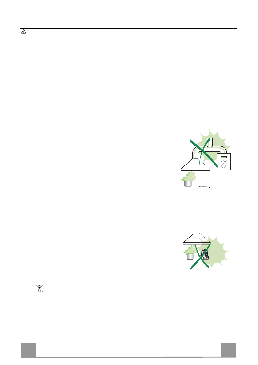
• Do not connect th e extractor hood to exhaust ducts carrying combustion
fumes (boilers, fireplaces, etc.).
• If the extractor is used in c onjunction with non-electrical a ppliances (e.g. gas
burning applia nces), a suffi cient degree of aeration must be guarantee d in
the room in order to prevent t he backfl ow of exha ust gas. T he kitch en must
have an opening communicating directly with the open air in order to
guarantee the entry of clean air.
USE
• The extractor hood has been designed exclusively for domestic use to
eliminate kitchen smells.
• Never use the hood for purposes other than for which it has been designed.
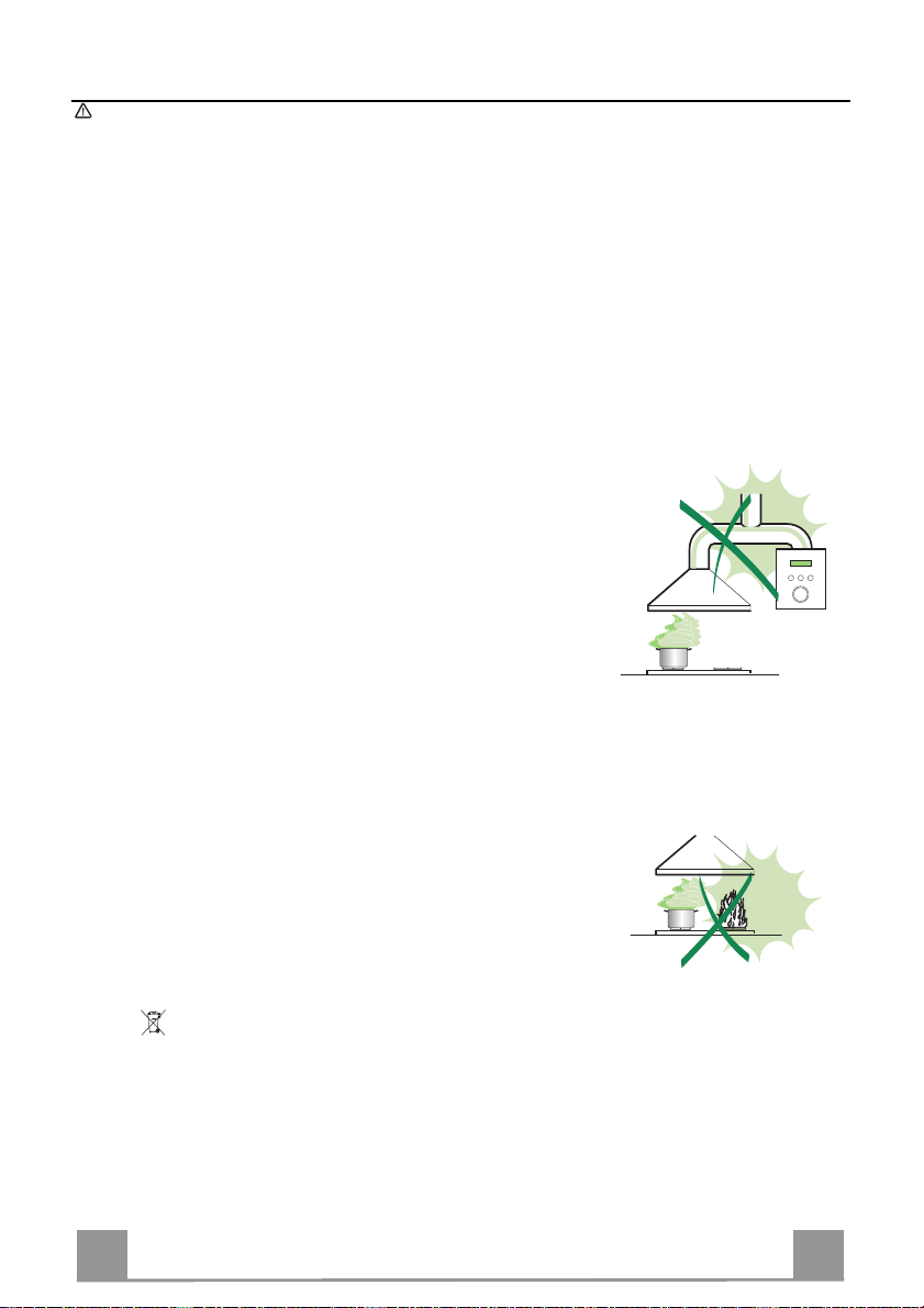
• Never leave high na ke d fla me s un de r the ho od wh en it i s in op er ati on .
• Adjust the flame inte nsity to direct it onto the bottom of the pa n only, making
sure that it does not engulf the sides.
• Deep fat fryers mus t be continuous ly monitored du ring use: overhe ated oil
can burst into flames.
• Do not flambè under the range hood; risk of fire
• T his appliance is not intended for use by persons (incl uding children) wi th
reduced physical , sensory or mental capabilitie s, or lack of ex perience and
knowledge, unless they have been given supervision or instruction
concerning use of the appliance by a person responsible for their safety.
• Children should be supervised to ensure that they do not play with the
appliance.
MAINTENANCE
• Sw itch off or unplug the appliance from the m ai ns s up ply be fo re ca rr yi n g ou t
any maintenance work.
• Clean and/or replace the Filters after the specified time period (Fire hazard).
• Clean the hood using a damp cloth and a neutral liquid detergent.
The symbol on the product or on its packaging indicates that this product may not be treated
as household waste. Instead it shall be handed over to the applicable collection point for the
recycling of electrical and electronic equipmen t. By ensuring this pr o duct is disposed of correctly,
you will help prevent potential negative consequences for the environment and human health,
which could otherwise be caused by inappropriate waste handling of this product. For more
detailed information about recycling of this product, please contact your local city office, your
household waste disposal service or the shop where you purchased the product.
3
3
Page 4

EN
CHARACTERISTICS
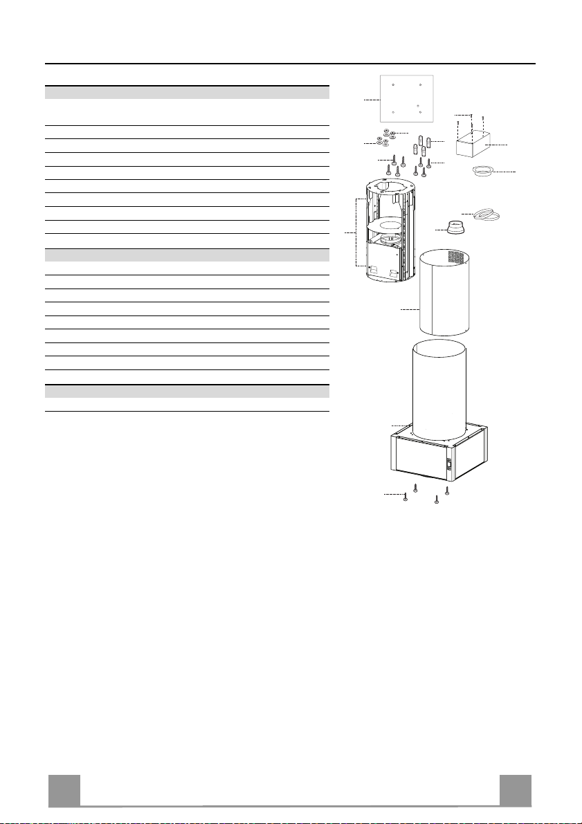
Components
Ref. Q.ty Product Components
1 1 Hood Body, complete with: Controls, Light, Blower,
Filters
2 1 Chimney Upper
7.1 1 Telescopic f rame complete with extrac tor, consist ing of:
7.1a 1 Upper frame
7.1b 1 Lower frame
9 1 Reducer Flange ø 150-120 mm
10 1 Flange ø 120 mm
15 1 Recirculation Air Outlet C onnection
25 Pipe clamps (not included)
Ref. Q.ty Installation Components
11 4 Wall Plugs ø 10
12c 4 Screws 2,9 x 6, 5
12f 4 Screws M6 x 10
12g 4 Screws M6 x 80
12h 4 Screws 5,2 x 70
21 1 Drilling template
22 4 6.4 mm int. dia washers
23 4 M6 nuts
Q.ty Documentation
1 Instruction Manual
7.1a
7.1
7.1b
21
12c
23
22
12g
1
11
12h
9
2
15
10
25
12f
4
4
Page 5

EN
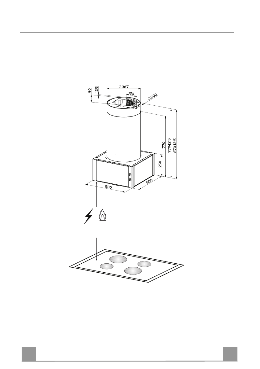
Dimensions
*
**
550 mm
* Dimensions of the hood in ducting version.
** Dimensions of the hood in recycling version.
5
5
Page 6
EN
INSTALLATION
Drilling the Ceiling/shelf and fixing the frame
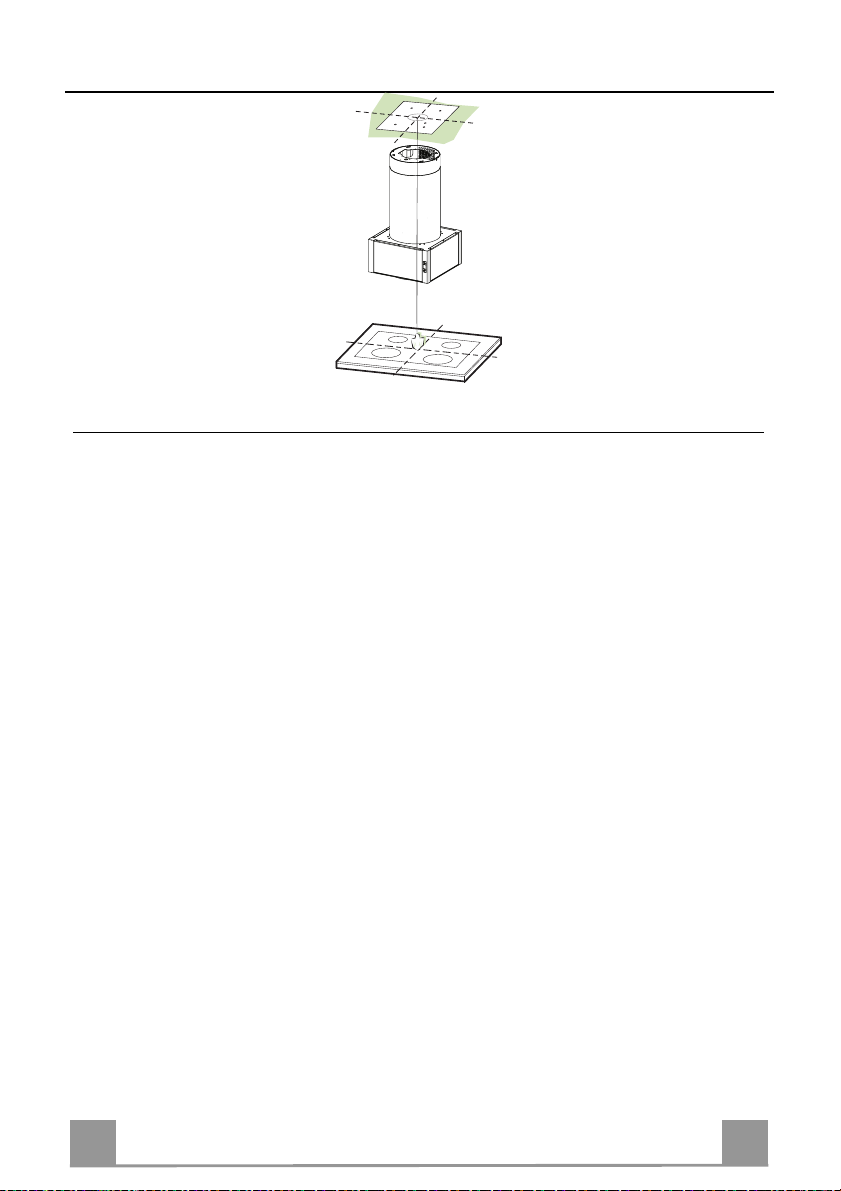
DRILLING THE CEILING/SHELF
• Use a plumb line to mark the centre of the hob on the ceiling/support shelf.
• Place the drilling template 21 provided on the ceiling/support shelf, making sure that the
template is in the correct position by lining up the axes of the template with those of the hob.
• Mark the centres of the holes in the template.
• Drill the holes at the points marked:
• For concrete ceilings, drill for plugs appropriate to the screw size.
• For hollow brick ceilings with wall thickness of 20 mm: drill ø 10 mm(immediately insert
the Dowels 11 supplied).
• For wooden beam ceilings, drill according to the wood screws used.
• For wooden shelf, drill ø 7 mm.
• For the power supply cable feed, drill ø 10 mm.
• For the air outlet (Ducted Versio n), drill according to t he diameter of the external air exhaust duct connection.
• Insert two screws of the following type, crossing them and leaving 4-5 mm from the ceiling:
• For concrete ceilings, use the appropriate plugs for the screw size (not provided).
• for Cavity ceiling with inner space, with wall thickness of approx. 20 mm, Screws 12h,
supplied.
• For wooden beam ceilings, use 4 wood screws (not provided).
• For wooden shelf, use 4 screws 12g with washers 22 and nuts 23, provided.
6
6
Page 7
EN
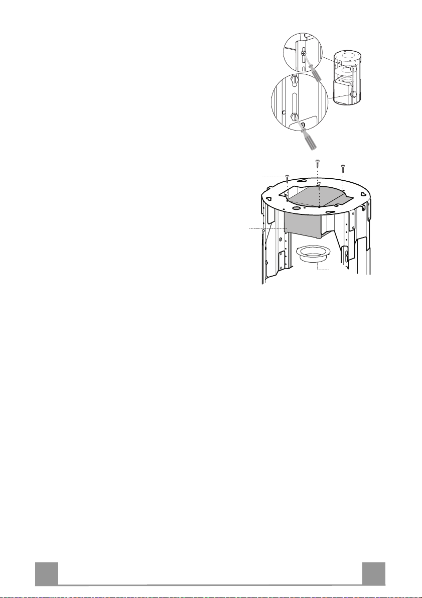
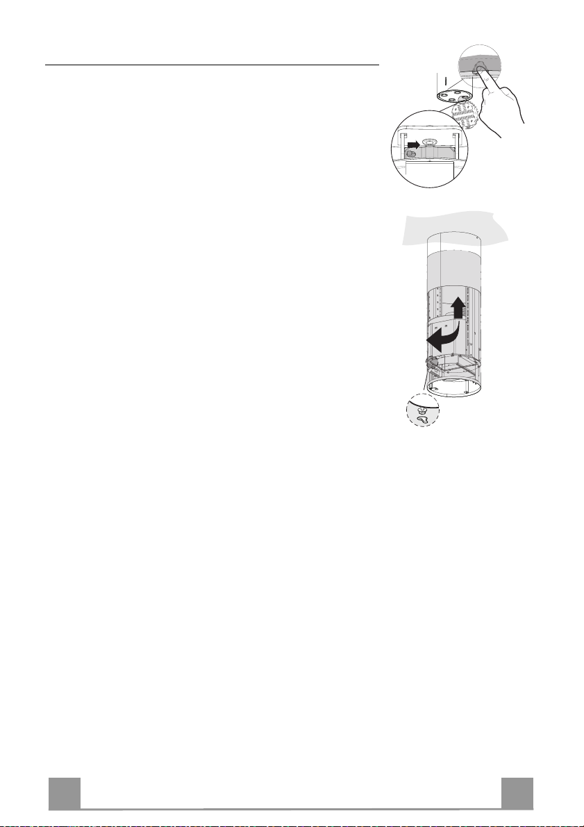
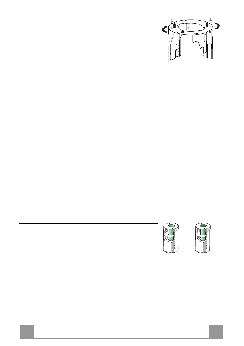
PREPARATION OF THE FRAME FOR THE HOOD IN RE-
CYCLING VERSION
In case the hood is used in recycling version it is necessary to prepare the fra me with all the necessary connection pieces. In order to make the installation easier i t is
necessary to lengthen the frame:
• Unscre w the two screws 2.1 fixing the upper chim-
ney to the frame and pull the chimney out.
• Unscrew the four safety screws p laced at the top in
the frame separation area. (A).
• Unscrew the eight metric screws connecting the two
columns, placed on both sides of the frame (B).
Installation of components in recycling version:
• Fix the recycling air outlet piece 15 to the upper part
of the frame using four 12c screws supplied with the
hood.
• Fix the flange (ø120) 10 to the lower part of the recycling air outlet 15.
• Put the reducer flan ge 9 on the hood body outlet.
• At this point, join the flanges with a pipe. In order to
calculate the height of the pipe it is necessary to estimate the height of the hood (mm) and subtract 615
mm. (H pipe = H hood-615).
• Lengthen the frame so that the pipe can be in serted.
Place the pipe between t he two flanges and bl ock it.
Make sure that the heigh t of the frame is correct co nsidering the height of the cooker hood (H frame = H
hood – 184). Adjust the height of the frame and
tighten again the earlier removed screws. Tighten
again the safety screws in order to give more stability
to the structure.
• Fix the pipe with the pipe clamps 25 supplied with
the hood.
A
B
12c
15
10
7
7
Page 8

EN
FIXING THE FRAME
2
1
1
2
9
ø 120ø 150
• Lift the frame up, making sure that the index over the frame
plate is turned forwards.
• Fit the frame slots onto the two screws inserted in the ceiling as
above, and turn unti l reach ing the centre of the adjustment slot.
• Tighten the two screws and fasten the other two screws provided; before locking the screws completely, it is possible to
adjust the frame by turning it, making sure that the screws do
not come out of their housing in the adjustment slot.
• The Frame must be securely fastened so as to support both the
weight of the Hood and the stress caused by occasional axial
pressure against the fitted Appliance. After fixing, make sure
that the base is stabl e even when the Fr ame is subjected to lateral stress.
• If the Ceiling is not strong enough in the area where the hood
is to be fixed, the Installer must strengthen the area using suitable plates and counterplates anchored to resistant structures.
Ducted version air exhaust system Connection
When installing the ducted version, connect the hood to the
chimney using either a flexible or rigid pipe ø 150 or 120 mm,
the choice of which is left to the installer.
• To install a ø 120 mm air exhaust connection, insert the reducer flange 9 on the hood body outlet.
• Fix the pipe using the pipe clamps 25 (not provided).
• Remove any activated charcoal filters.
8
8
Page 9
EN
Installing of the chimney and fixing of the hood
2
1
When the hood is installed in recycling version the chimney has
to be positioned with the slots upwards. When the hood is installed in ducting version it has to be positioned in the opposite
way.
• Place the chi mney on the fra me a nd fix it t o t he up per part o f it
with the earlier removed screws. When installing the hood in
recycling version make sure th at the slots corresp ond to the air
outlet of the recycling air outlet piece 15.
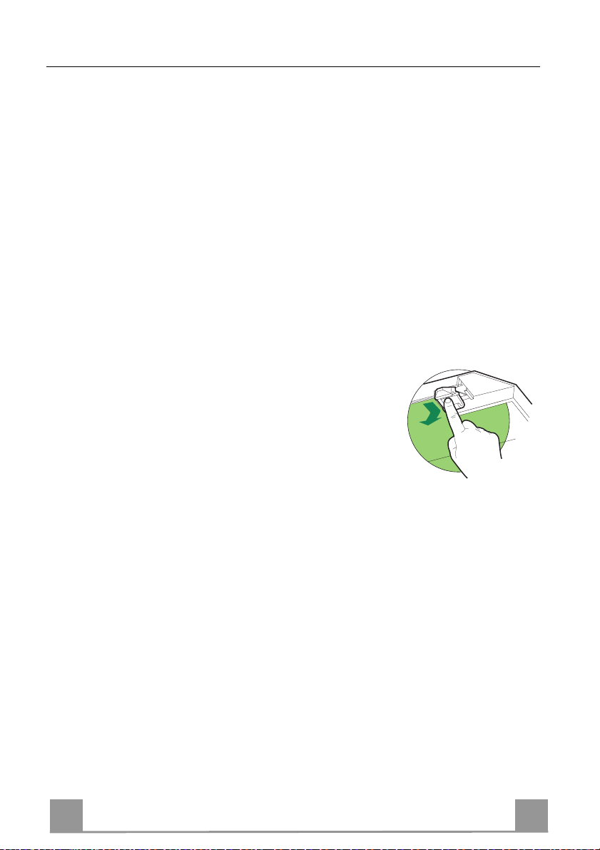
• Open the lighting unit by slightly pulling the notch. Remove
the unit from the hood by sliding the fixing pivot.
• Remove the filter pushing it towards the back side of the hood
unit and simultaneously pulling downwards.
• Remove possible charcoal filters.
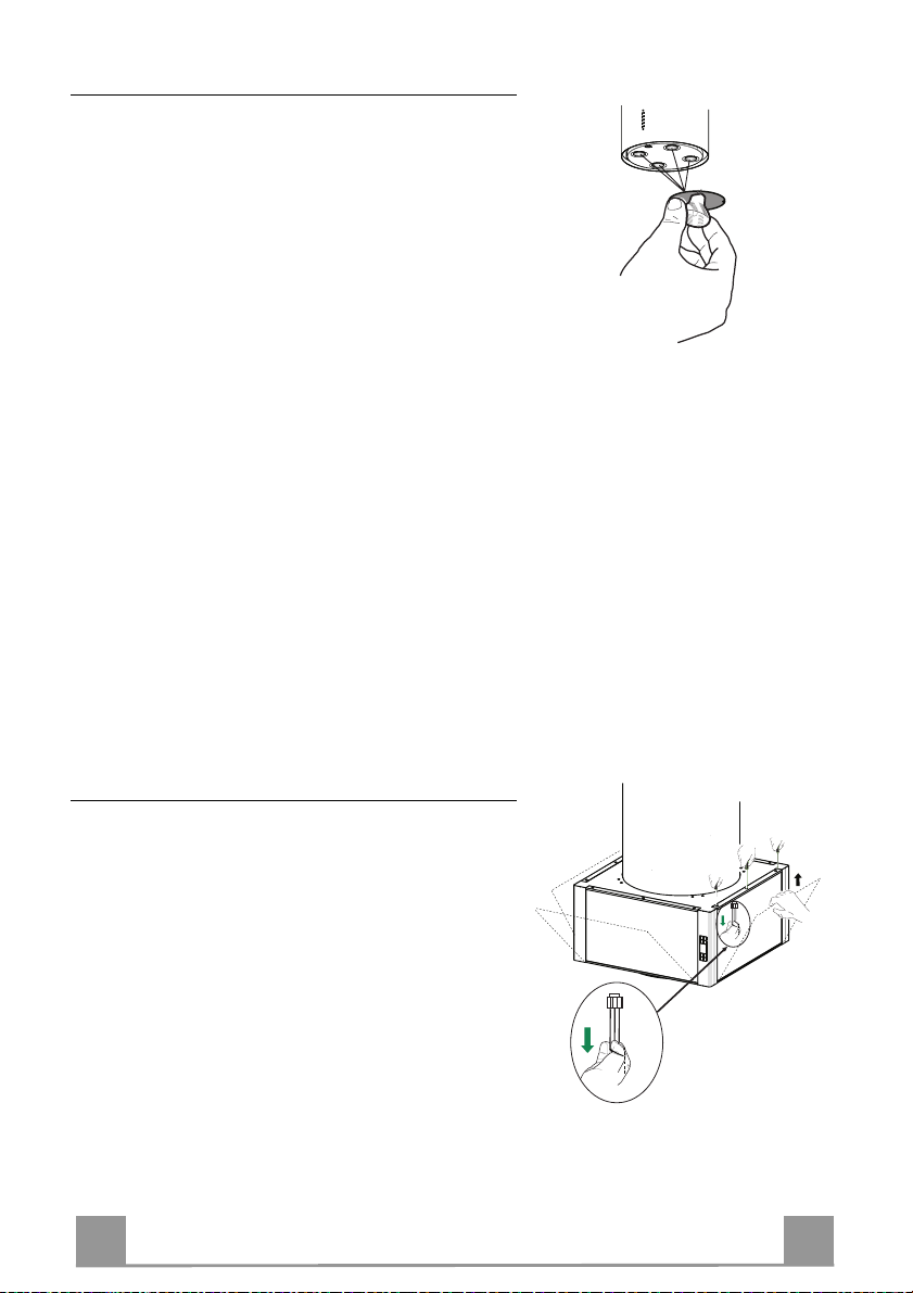
• In order to fix the hood body to the frame insert the 4 screws
12f i n their seats. It is necessar y to leave at least 4-5 mm gap
between the screw heads and t he frame plate.
• Hook the hood canopy to the frame and turn it to the left until
it reaches the stop, then lock the screws immediately to prevent
the hood canopy from falling out accidentally.
9
9
Page 10

EN 110
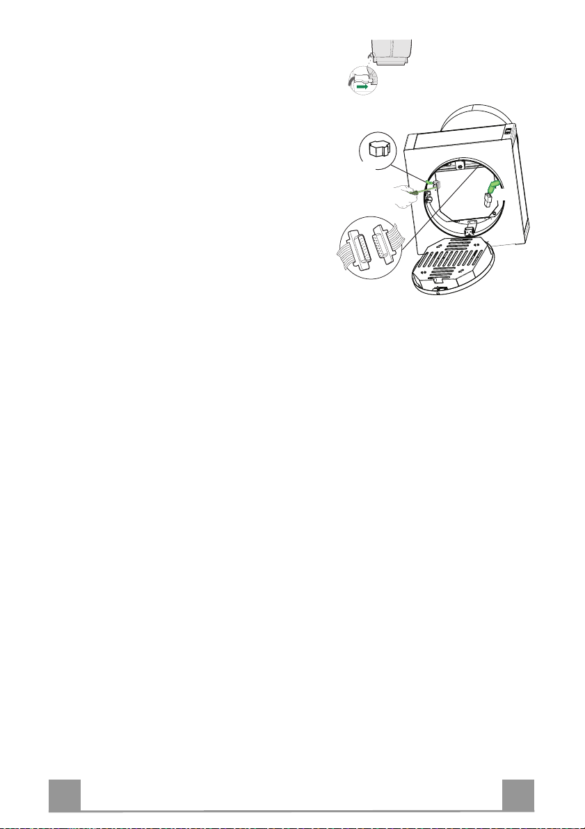
ELECTRICAL CONNECTION
• Connect the Hood to the Mains power supply, inserting a two-pole switch with a contact gap of at least 3
mm.
• Make sure that the Power cable has been properly
inserted into the Suction fan socket.
• Fasten the commands connector Cmd.
• Fasten the Overhead lights connector Lux to the
socket provided behind the lighting unit cover.
• From the inside, open the Cover of Neon terminal
box by removing the screws.
• Fasten the remaining free conn ector to the one provided in the Neon terminal b ox, then close the cover
and fix it in the predisposed place.
• For the recirculation version, fit the Activated charcoal odour filter.
• Replace the Grease filter and then the lighting unit.
Neon
Lux
Cmd
Page 11
EN 111
USE
Activates automatic shutdown with a 30' delay.
A
B
D
C
E
GH
F
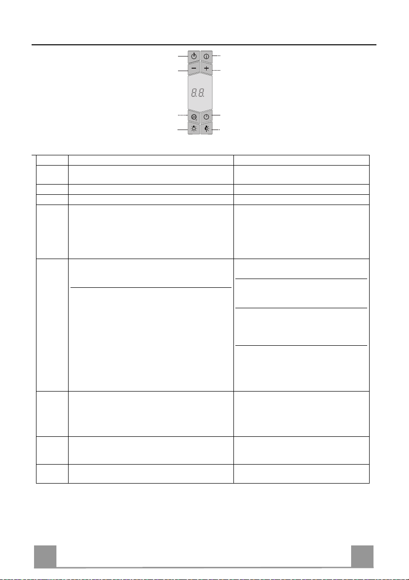
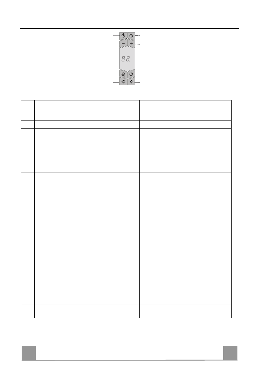
Control panel
Button Function Display
A Turns the suction motor on and off at the last
Displays the speed setting
speed used.
B Decreases the operating speed.
C Increases the operating speed.
D Activates intensive speed from any other speed,
even with the motor stopped. Intensive speed is
Displays HI and the sp ot at the bottom
right flashes once a second.
timed to run for 10 minutes, after which the system will return to the speed that was set previously. Suitable to deal with the highest level of
cooking fumes.
E Starts the motor at a speed that allows recircula-
tion of 100 m3/h for 10 minutes in every hour;
after which the motor stops.
When the filt ers alarm is tri ggered, the alar m can
be reset by pressing and holding this button for
approximately 3 seconds. These indications are
only visible when the motor is turned off.
Displays 24 and the spot at the bottom
right flashes, while the motor is running.
When the p roc edu re h a s b een c omplet ed ,
the indication previously displayed will
turn off:
FF indicates th e need to wash t he metal
grease filters. The alarm is triggered after the Hood has been operating for 100
actual working hours.
EF indicates t he n eed t o ch ange t he a cti -
vated charcoal filters, and also to wash
the metal grease filters. The alarm is
triggered after the Hood has been operating for 200 actual working hours.
F
Suitable to complete elimination of residual
odours. It can b e activated from any positi on, and
is deactivated by pressing the button or turning the
Alternately displays the working speed
and the time remaining until the hood is
turned off. The spot at the bottom right
flashes.
motor off.
G Turns the lighting system (overhea d s potli ghts) on
and off. If pressed and held for 2 seconds it turns
the side lights (Neon strips) on and off.
H Turns the low intensity lighting system (overhead
spotlights) on and off.
Page 12

EN 112
MAINTENANCE
REMOTE CONTROL (OPTIONAL)
The appliance can be controlled using a remote control powered
by a 1.5 V carbon-zinc alkaline batteries of the standard LR03AAA type (not included).
• Do not place the remote control near to heat sources.
• Used batteries must be disposed of in the proper manner.
Metal grease filters
Filters can be washed in the dish machine. They need to be
washed when FF-sign appears on the display or in any case every
2 months, or even more frequently in case of particularly intensive use of the hood.
Alarm reset
• Switch off the hood and the lights. If the 24h-function has been
activated this has to be deactivated.
• Press the E-key till the display is unlit.
Cleaning the filters
• Open the lighting unit by pulling on the nocth.
• Remove the filters one by one pushing them towards the back
side of the hood unit and simultaneously pulling downwards.
• Any kind of bending of the filters has to be avoided when
washing them. Before fitting them again into the hood make
sure that they are completely dry. (The colour of the filter surface may change throughout the time but this has no influence
to the filter efficiency).
• When fitting the filters into the hood pay attention that they are
mounted in correct position the handle facing outwards.
• Replace the li ghting unit.
Page 13
EN 113
Charcoal filter (recycling version)
• This filter cannot be washed or regenerated. It must be replaced when the EF appears on the
display or at least once every 4 months.
Activation of the alarm signal
• In the recycling version hoods the filter saturation alarm must be activated during the installation or later.
• Switch off the hood and the lights.
• Disconnect the hood from the mains supply.
• When restoring the connection press and hold B-key.
• When releasing the key two rotating rectangles appear on the display.
• Within 3 seconds press the B-key until a flashing confirmation appears on the dispaly:
• 2 flashes with EF - charcoal filter saturation alarm ACTIVATED
• 1 flash with EF - charcoal filter saturation alarm DEACTIVATED.
REPLACING THE CHARCOAL FILTER
Reset of the alarm signal
• Switch off the hood and the lighting. If the 24h-function has
been activated this has to be deactivated.
• Press the E-key until the display is unlit.
Replacing of the filter
• Open the lighting unit by pulling on the nocth.
• Remove the metal grease filters.
• Remove the saturated charcoal filter by releasing the fixing
hooks
• Fit the new filter and fasten it in its correct position.
• Put the metal grease filters in their seats.
• Replace the li ghting unit.
Page 14
EN 114
Lighting
LIGHT REPLACEMENT
20 W halogen light.
• Extract the lamp from the lamp holder by pulling
gently.
• Replace with ano ther of the same type, making sure
that the two pins are properly inserted in the lamp
holder socket holes.
Lighting
CHANGING LAMPS
9 W Neon Lamp
• Unfasten the screws and remove the metal glass fixing element, making sure you do not drop it.
• Remove the Glass.
• Replace the neon lamp from the inside, pulling it
downwards and fitting a new one with the same characteristics.
• To reassemble, repeat the ab ove op eration s in reverse
order.
Page 15
IT 115
CONSIGLI E SUGGERIMENTI
Questo libretto di istruzioni per l'uso è previsto per più versioni dell' appare
c
chio.
É possibile che siano descritti singoli particolari della dotazione, che non
riguardano il Vost ro appar ec chi o.
INSTALLAZIONE
• Il produttore declina qualsiasi responsabilità per danni dovuti ad installazione non
corretta o non confor me alle regole d ell’art e.
• La distanza minima di sicurezza tra il Piano di cottura e la Cappa deve essere di
650 mm, (alcuni modelli possono essere installati ad un’altezza inferiore, fare
riferimento ai paragr af i i ngombro e i nst all az ione) .
• Verificare che la tensione di rete corrisponda a quella riportata nella targhetta
posta all’interno della Cappa.
• Per Apparecchi in Classe I
garantisca un cor ret to sc ar ico a t err a.
• Collegare la Cappa all’uscita dell’aria aspirata con tubazione di diametro pari o
superiore a 120 mm. Il percorso della tubazione deve essere il più breve
possibile.
• Non collegare la Cappa a condotti di scarico dei fumi prodotti da combustione
(caldaie, caminet ti , ec c.) .
• Nel caso in cui nella stanza vengano utilizzati sia la Cappa che apparecchi non
azionati da energia elettrica (ad esempio apparecchi utilizzatori di gas), si deve
provvedere ad una aerazione sufficiente dell’ambiente. Se la cucina ne fosse
sprovvista, praticare un’apertura che comunichi con l’esterno, per garantire il
richiamo d’aria puli ta.
USO
• La Cappa è stata progettata esclusivamente per uso domestico, per abbattere gli
odori della cucina.
• Non fare mai uso improprio dell a Cappa.
• Non lasciare fiamme libere a for te i nt ensi tà sot to l a Cappa in f unzi one.
• Regolare sempre le fiamme in modo da evitare una evidente fuoriuscita laterale
delle stesse ri spet t o al fondo dell e p entol e.
• Controllare le friggitr ici dur ante l ’us o: l ’ oli o surrisc al dato pot rebb e i nfi ammars i .
• Non preparare alimenti fl ambè s ott o la c appa da c uci na; per i col o d'inc en dio.
• Q uesto ap parecchio non deve essere u tilizzato da perso ne (bambi ni inclusi) co n
ridotte capacità psichiche, sensoriali o mentali, oppure da persone senza
esperienza e conoscenza, a meno che non siano controllati o istruiti all’uso
dell’apparecchio da person e r esponsabili della loro sicurezza.
• I bambini devono essere supervisionati per assicurarsi che non giochino con
l’apparecchio.
MANUTENZIONE
• Prima di procedere a qualsiasi operazione di manutenzione, disinserire la Cappa
togliendo la spina elettrica o spegnendo l’interruttore generale.
• Effettuare una scrupolosa e tempestiva manutenzione dei Filtri secondo gli
intervalli cons igl iat i (Ris c hio di incendi o).
• Per la pulizia de lle su perfici d e lla C a pp a è sufficie n te u tilizzare un panno umido e
detersivo liqui do neutr o.
a
accertarsi che l’impianto elettrico domestico
Il simbolo sul prodotto o sulla confezione indica che il prodotto non deve essere considerato
come un nor m ale rifiuto domes ti c o , m a d eve essere portat o n el p unto di raccolta a ppropriato per
il riciclaggio di apparecchiature elettriche ed elettroniche. Provvedendo a smaltire questo
prodotto in modo appropriato, si contribuisce a evitare potenziali conseguenze negative per
l’ambiente e per la salute, che potrebbero derivare da uno smaltimento inadeguato del prodotto.
Per inform azio ni pi ù det tagli at e sul r icic lag gio di ques to prodot to, c ont attar e l’u ffici o com un ale, il
servizio locale di smaltimen to rifiut i o il negozio in cu i è stato acqu ista to il prodo tto .
Page 16
IT 116
CARATTERISTICHE
Componenti
Rif. Q.tà Componenti di Prodotto
1 1 Corpo Cappa completo di: Comandi, Luce, Fi ltri, Cami -
no Inferiore
2 1 Camino superiore
7.1 1 Traliccio tel escopico completo di Aspiratore,formato da:
7.1a 1 Traliccio superiore
7.1b 1 Traliccio inferiore
9 1 Flangia di riduzione ø 150-120 mm
10 1 Flangia ø 120 mm
15 1 Raccordo Usci ta Aria Filtrante
25 Fasc ette stringitubo (non incluse)
Rif. Q.tà Componenti di Installazione
11 4 Tasselli ø 10
12c 4 Viti 2,9 x 6,5
12f 4 Viti M6 x 15
12g 4 Viti M6 x 80
12h 4 Viti 5, 2 x 70
21 1 Dima di foratura
22 4 Rondelle ø 6,4
23 4 Dadi M6
Q.tà Documentazione
1 Libretto Istruzioni
7.1a
7.1
7.1b
21
12c
23
22
12g
1
11
12h
9
2
15
10
25
12f
Page 17
IT 117
Ingombro
*
**
550 mm
* Dimensioni per cappa in versione aspirante.
** Dimensioni per cappa in versione filtrante.
Page 18
IT 118
INSTALLAZIONE
6
Foratura Soffitto/Mensola e Fissaggio Traliccio
FORATURA SOFFITTO/MENSOLA
• Con l’ausilio di un Filo a piombo riportare sul Soffitto/Mensola di supporto il centro del
Piano di Cottura.
• Appoggiare al Soffitto/Mensola la Dima di Foratura 21 in dotazione, facendo coincidere il
suo centro al centro proiettato e allineando gli assi della Dima agli assi del Piano di Cottura.
• Segnare i centri dei Fori della Dima.
• Forare i punti seguenti:
• Soffitto in Calcestruzzo massiccio: secondo Tasselli per Calcestruzzo impiegati.
• Soffitto in Laterizio a camera d’aria, con spessore resistente di 20 mm: ø 10 mm (inserire
subito i Tasselli 11 in dotaz ione ) .
• Soffitto in Travatura di Legno: secondo Viti per Legno impiegate.
• Mensola in Legno: ø 7 mm.
• Passaggio del Cavo elettrico di Alimentazione: ø 10 mm.
• Uscita Aria (Versione Aspirante): secondo diametro del collegamento alla Tubazione di
Evacuazione Esterna.
• Avvitare, incrociandole e lasciando 4-5 mm dal soffitto, due viti:
• per Calcestruzzo massiccio, Tasselli per Calcestruzzo, non in dotazione.
• p er Laterizio a ca mera d’aria, co n spesso re resistente d i 20 mm circa, V iti 12h, in dotazio-
ne.
• per Travatura di legno, Viti per legno, non in dotazione.
• per Mensola in Legno, viti 12g con Rondelle 22 e Dadi 23, in dotazione.
Page 19

IT 119
PREPARAZIONE DEL TRALICCIO PER LA CONNESIONE
FILTRANTE
Nel caso in cui si installi la cappa in versione filtrante
bisogna predisporre nel traliccio tutti i raccordi necessari per tale versione. Per facilitare l’installazione dei particolari per la versione filtrante è necessario allungare il
traliccio, procedere come segue:
• Svitare le due viti che fissano il camino superiore 2.1
al traliccio e sfilare il camino.
• Svitare le quattro viti di sicurezza poste in alto nella
zona di separazione del traliccio. (A)
• Svitare le otto viti metriche che uniscono le due co-
lonne, poste ai lati del traliccio. (B)
Installazione dei componenti per versione filtrante:
• Fissare il raccordo filtrante 15 alla parte superiore del
traliccio utilizzando le 4 viti 12c in dotazione.
• Agganciare con movimento rotativo la flangia (ø120)
10 alla parte inferiore del raccordo filtrante 15.
• Inserire la flangia di riduzione 9 sull’uscita dell’aspiratore.
• A questo punto bisogna collegare le due flangie con
un tubo, per calcolare l’altezza del tubo occorre stimare l’altezza della cappa (mm) e sottrarre 615 mm.
(H tubo = H cappa-615).
• Allungare il traliccio tanto da permettere l’inserimento del tubo e riposizionarlo bloccando il tubo tra
le due flangie. V erificare se l’altezza del traliccio è
adeguata all’altezza desiderata della cappa (H traliccio = H cappa – 184). Regolare l’alt ezza desiderata
del traliccio e riavvitare le viti precedentemente tolte.
Per garantire una maggiore stabilità al traliccio riavvitare le quattro viti di sicurezza sull’ultimo foro disponibile.
• Fissare il tubo con le fascette stringitubo 25 in dota-
zione.
A
B
12c
15
10
Page 20
IT 220
FISSAGGIO TRALICCIO
2
1
1
2
9
ø 120ø 150
• Sollevare il traliccio facendo attenzione che l’indice posto sopra la piastra del traliccio si a nella parte anteriore.
• Incastrare le asole del traliccio sulle due viti predisposte precedentemente al soffitto e ruotare fino al centro dell’asola di regolazione.
• Stringere le due viti e avvitare le altre due in dotazione; prima
di serrare definitivamente le viti è possibile effettuare delle regolazioni ruotando il traliccio, facendo attenzione che le viti
non escano dalla sede dell’asola di regolazione.
• Il fissaggio d el Traliccio deve essere sicu ro in relazione sia al
peso della Cappa sia alle sollecit azioni causate da occasionali
spinte laterali all’ Apparecchio montato. A fissaggio avvenu to
verificare quindi ch e la base sia stabile anche se il Trali ccio è
sollecitato a flessione.
• In tutti i casi in cui il Soffitto non fosse sufficientemente robusto sul punto di sospensione, l’Installatore dovrà provvedere a
irrobustirlo con opportune piastre e contropiastre ancorate a
parti strutturalmente resistenti.
Connessione Uscita aria Versione Aspirante
Per installazione in Versione Aspirante collegare la Cappa alla
tubazione di uscita per mezzo di un tubo rigido o flessibile di
ø 150 o 120 mm, la cui scelta è lasciata all’installatore.
• Per collegamento con tubo ø 120 mm, inserire la Flangia di
riduzione 9 sull’Uscita del Corpo Cappa.
• Fissare il tubo con adeguate fascette stringitubo 25(non incluse).
• Rimuovere eventuali filtri al carbone attivo.
Page 21

IT 221
Montaggio Camino e Fissaggio Corpo Cappa
2
1
Il camino va girato con le asole verso l’alt o in caso di install azione della cappa in versione filtrante, viceversa con le asole verso il
basso in caso di installazione in versione aspirante.
• Infilare dal basso verso l’alto il Camino superiore e fissarlo
nella parte superiore al Traliccio co n 2 Viti tolt e in preceden za,
prestando attenzione nel caso di installazione filtrante che le
asole del camino sia in corrispondenza d ell’uscit a del raccordo
filtrante 15.
• Aprire il gruppo illuminazione tirandolo sull’apposita intacca,
sganciarlo dal corpo cappa facendo scorrere l’apposito perno di
fissaggio.
• Togliere il Filtro Antigrasso, spingendolo verso la parte posteriore del gruppo e tir ando contemporaneamente verso il basso.
• Togliere eventuali Filtri Antiodore al Carbone attivo.
• Predisporre il fissaggio del corpo cappa al traliccio avvitando
le 4 Viti 12f nelle apposite sedi.Lasciare almeno 4-5 mm di
spazio tra la testa della vite e la piastra del traliccio.
• Agganciare il corpo capp a al traliccio e ruotare verso sinistra
fino alla battuta, procedere immediatamente al bloccaggio del le
viti così da evitare un’accidentale caduta del corpo cappa.
Page 22
IT 222
CONNESSIONE ELETTRICA
• Collegare la Cappa all’Alimentazione di Rete interponendo un Interruttore bipolare con apertura dei
contatti di almeno 3 mm.
• Assicurarsi che il connettore del Cavo alimentazione
sia correttamente inserito nella presa dell’Aspiratore.
• Collegare il connettore dei Comandi Cmd.
• Collegare il connettore dei Faretti Lux alla presa predisposta dietro al coperchio del gruppo illuminazione.
• Dall’interno, ap rire il cop erchi o della Scat ol a conn essione elettrica Neon svitando le Viti.
• Collegare il Connettore rimasto libero a quello già
presente nella Scatola conn essione Neon, richiudere
il coperchio e montare la Scatola nel posto predisposto.
• Per la Versione Filtrante montare il Filtro Antiodore
al Carbone attivo.
• Rimontare il Filtro Antigrasso e successivamente il
gruppo illuminazione.
Neon
Lux
Cmd
Page 23
IT 223
USO
A
B
D
C
E
GH
F
Quadro comandi
Tasto Funzione Display
Accende e spegne il motore di aspirazione
A
Visualizza la velocità impostata
all’ultima velocità utilizzata.
B Decrementa la velocità di eser cizio.
C Incrementa la velocità di esercizio.
Attiva la velocità intensiva da qualsiasi velocità
D
anche da motore spento, tale velocità è temporiz-
Visualizza HI e il punto in basso a destra
lampeggia una volta al secondo.
zata a 10 minuti, al termine del tempo il sistema
ritorna alla velocità precedentemente impostata.
Adatta a front eggiare le mass ime emissi oni di fumi di cottura.
Attiva il motore ad una velocità che consente
E
un’aspirazione di 100 m
3
/h per 10 minuti ogni ora,
terminati il motore si ferma.
Con l’allarme filtri in corso premendo il tasto per
circa 3 secondi si effettua il reset dell’al-larme.
Tali segnalazioni sono visibili solo a motore spento.
Visualizza 24 e il punto in basso a destra
lampeggia, mentre il motore è in funzione
Terminata la procedura si spegne la segnalazione prec edentemente visualizzata:
FF segnala la necessità di lavare i filtri
antigrasso metallici. L’allarme entra
in funzione dopo 100 ore di lavoro effettivo della Cappa.
EF segnala la necessità di sostituire i filtri
al carbone attivo e devono anche essere lavati i fi ltri antigrasso met allici.
L’allarme ent ra in funzion e dopo 200
ore di lavoro effett ivo della Cappa.
Attiva lo spegnimento automatico ritardato di 30’.
F
Adatto per completare l’eliminazione di odori
residui. Attivabile da qualsiasi posizione, si disattiva premendo il tasto o spegnendo il motore.
Accende e spegne l’impianto di illuminazione
G
Visualizza alternativamente la velocità di
esercizio e il tempo rimanente allo spegnimento della cappa. Il punto in basso a destra lampeggia.
(Faretti). Tenendolo premuto per 2 secondi accende e spegne l’illuminazione laterale (Neon).
Accende e spegne l’impianto di illuminazione ad
H
intensità ridotta (Faretti).
Page 24

IT 224
MANUTENZIONE
TELECOMANDO (OPZIONALE)
Questo apparecchio può essere c omandato per mezzo di un tel ecomando, alimentato con pile alcaline zinco-carbone da 1,5 V del
tipo standard LR03-AAA (non incluse).
• Non riporre il telecomando in prossimità di fonti di calore.
• Non disperdere le pile nell’ambiente, depositarle negli appositi
contenitori.
Filtri antigrasso metallici
Sono lavabili anche in lavastoviglie, e necessitano di essere lavati
quando sul display appare FF o almeno ogni 2 mesi circa di utilizzo o più frequentemente, per un uso particolarmente intenso.
Reset del segnale di allarme
• Spegnere le Luci e il Motore di aspirazione, quindi qualora
fosse attivata la funzione 24h disattivarla.
• Premere il tasto E sino allo spegnersi del display.
Pulizia Filtri
• Aprire il gruppo illuminazione tirandolo sull’apposita intacca.
• Togliere i Filtri uno alla volta, spingendoli verso la parte posteriore del gruppo e tir ando contemporaneamente verso il basso.
• Lavare i Filtri evitando di piegarli, e lasciarli asciugare prima
di rimontarli. (Un’event uale cambiamento del colore dell a superficie del filtro, che potrebbe verificarsi nel tempo, non pregiudica assolutamente l’efficienza dello stesso.)
• Rimontarli facendo attenzione a mantenere la maniglia verso la
parte visibile esterna.
• Richiudere il gruppo illuminazione.
Page 25

IT 225
Filtri antiodore al Carbone attivo (Versione Filtrante)
• Non è lavabile e non è rigenerabile, va sostituito quando sul display appare EF o almeno
ogni 4 mesi.
Attivazione del segnale di allarme
• Nelle Cappe in Versione Filtrante, la segnalazione di Allarme saturazione Filtri va attivata al
momento dell’installazione o successivamente.
• Spegnere le Luci e i l Motore di aspirazione.
• Scollegare la cappa dall’alimentazione di rete.
• Ripristinare il collegamento tenendo premuto il tasto B.
• Rilasciando il tasto sul display compaiono due rettangoli in rotazione.
• Entro 3 secondi premere il Tasto B sino alla conferma che appare sul display:
• 2 lampeggi scritta EF - Allarme saturazione Filtro Carbone attivo ATTIVATO
• 1 lampeggio scritta EF - Allarme saturazione Filtro al Carbone attivo DISATTIVATO.
SOSTITUZIONE FILTRO ANTIODORE AL CARBONE ATTIVO
Reset del segnale di allarme
• Spegnere le Luci e il Motore di aspirazione, quindi qualora
fosse attivata la funzione 24h disattivarla.
• Premere il tasto E sino allo spegnersi del display.
Sostituzione Filtro
• Aprire il gruppo illuminazione tirandolo sull’apposita intacca.
• Togliere i Filtri antigrasso metallici.
• Rimuovere il Filtro antiodore al Carbone attivo saturo, agendo
sugli appositi agganci.
• Montare il nuovo Filtro agganciandolo nella sua sede.
• Rimontare i Filtri antigrasso metallici.
• Richiudere il gruppo illuminazione.
Page 26

IT 226
Illuminazione
SOSTITUZIONE LAMPADE
Lampade alogene da 20 W
• Estrarre la Lampada dal Supporto.
• Sostituirla con una nuova di uguali caratteristiche,
facendo attenzione ad inserire correttamente i due
spinotti nella sede del Supporto.
Illuminazione
SOSTITUZIONE LAMPADE
Lampade Neon 9 W.
• Svitare le Viti e togliere l’angolare metallico che fissa il vetro facendo attenzione a non farlo cadere.
• Estrarre il Vetro.
• Sostituire dall’interno la lampada Neon, tirandola
verso il basso, con una nuova di uguali caratteristiche.
• Rimontare tutt o in sequenza inversa.
Page 27

FR 227
CONSEILS ET SUGGESTIONS
La présente notice d'emploi vaut pour plusieurs versions de l'appareil. Elle peut
contenir des descriptions d'access oi res ne fi gurant pas dans votre ap parei l.
INSTALLATION
• Le fabricant décline toute responsabilité en cas de dommage dû à une ins ta llatio n n on
correcte ou non conforme aux règles de l ’ art.
• La distance minimale de sécurité entre le plan de cuisson et la hotte doit être de 650
mm au moins (certains modèles peuvent être installés à une hauteur inférieure : se
reporter aux paragraphes « E ncombrem ent » et « Inst allat ion »).
• Vérifier que la tension du secteur correspond à la valeur qui figure sur la plaquette
apposée à l’intérieur de la hotte.
• Pour les Appareils appartenant à la Ière Classe, veiller à ce que la mise à la terre de
l’installation électrique domestique ait été effectuée conformément aux normes en
vigueur.
• Connecter la hotte à la sortie d’air aspiré à l’aide d’une tuyauterie d’un diamètre égal ou
supérieur à 120 mm. Le parcours de la tuyaut eri e doit être le plus court possibl e.
• Ne pas connecter la hotte à des conduites d’évacuation de fumées issues d’une
combustion tel que (Chaudièr e, chemi née, et c…).
• Si vous utilisez des appareils qui ne fonctionnent pas à l’électricité dans la pièce ou est
installée la hotte (par exemple: des appareils fonctionnant au gaz), vous devez prévoir
une aération suffisante du milieu. Si la cuisine en est dépourvue, pratiquez une
ouverture qui communique avec l ’ext érieur pour garant ir l’i nfiltr ation de l’ai r pur .
UTILISATION
• La hotte a été conçue exclusivement pour l’usage domestique, dans le but d’éliminer
les odeurs de la cuisine.
• Ne jamais utiliser abusivement la hotte.
• Ne pas laisser les flammes libres à forte intensité quand la hotte est en servi ce.
• Toujours régler les flammes de manière à éviter toute sortie latérale de ces dernières
par rapport au fond des marmites.
• Contrôler les friteuses lors de l’utilisation car l’huil e surchauf fée pourr ait s’enf lammer .
• Ne pas préparer d’aliments flambés sous la hotte de cuisine : ri sque d’i ncendie
• Cet appareil ne doit pas être utilisé par des personnes (y compris les enfants) ayant
des capacités psychiques, sensorielles ou mentales réduites, ni par des personnes
n’ayant pas l’expérience et la connaissance de ce type d’appareils, à moins d'être so us
le contrôle et la formation de personn es respo nsables de l eur sécuri té.
• Les enfants doivent être surveillés pour s'assurer qu'i ls ne jouent pas avec l'app arei l.
ENTRETIEN
• Avant de procéder à toute opérati on d’entretien, retir er la hotte en retirant la f iche ou en
actionnant l’interrupteur général.
• Effectuer un entretien scrupuleux et en temps dû des Filtres, à la cadence conseillée
(Risque d’incendie).
• Pour le nettoyage des surfaces de la hotte, il suffit d’utiliser un chiffon humide et
détersif liquide neutre.
Le symbole sur le produit ou son emballage indique que ce produit ne peut être traité comme
déchet ménager. Il doit plutôt être remis au point de ramassage concerné, se chargeant du
recyclage du matériel électrique et électronique. En vous assurant que ce produit est éliminé
correctement, vous favorisez la prévention des conséquences négatives pour l’environnement et la
santé humaine qui, sinon, seraient le résultat d’un traitement inapproprié des déchets de ce produit.
Pour obtenir plus de détails sur le r ecyclage de ce produit, ve uillez prendre con tact avec le bureau
municipal de votre région, votre service d’élimination des déchets ménagers ou le magasin où vous
avez acheté le produit.
Page 28

FR 228
CARACTERISTIQUES
Composants
Réf. Q.té Composants du produit
1 1 Corps de Hotte comprenant : Commandes, Éclairage,
Filtres
2 1 Conduit supérieur
7.1 1 Treillis télescopique muni d’un di spositif d’aspiration et
comprenant :
7.1a 1 Treillis supérieur
7.1b 1 Treillis inférieur
9 1 Flasque de réduction ø 150-120 mm
10 1 Flasque ø 120 mm
15 1 Raccord Sortie de l’Air
25 Colliers serre-tube (non compris)
Réf. Q.té Composants de l’installation
11 4 Chevilles ø 10
12c 4 Vis 2,9 x 6,5
12f 4 Vis M6 x 15
12g 4 Vis M6 x 80
12h 4 Vis 5,2 x 70
21 1 Gabarit de perçage
22 4 Rondelles ø 6,4
23 4 Écrous M6
Q.té Documentation
1 Notice d’emploi
7.1a
7.1
7.1b
21
12c
23
22
12g
1
11
12h
9
2
15
10
25
12f
Page 29

FR 229
Encombrement
*
**
550 mm
* Dimensions pour hotte en version aspirante.
** Dimensions pour hotte en version filtrante.
Page 30

FR 330
INSTALLATION
Perçage Plafond/Étagère et Fixation Treillis
PERÇAGE PLAFOND/ETAGERE
• À l’aide d’un Fil à plomb, reporter sur le Plafond/Étagère de support le centre du Plan de
Cuisson.
• Poser contre le Plafond/Étagère le Gabarit de Perçage 21 fourni avec l’appareil, en faisant
coïncider son centre avec le centre projeté et en alignant les ax es du Gabarit avec les axes du
Plan de Cuisson.
• Marquer les centres des Trous du Gabarit.
• Percer les trou s qui ont été marqués:
• Plafond en Béton massif: en fonction des Goujons pour Béton utilisés.
• Plafond en Briques avec chambre à air, avec ép aisseur résist ante de 2 0 mm: ø 10 mm (in-
sérer immédiatement les Chevilles 11 fournies avec l’appareil).
• Plafond en Poutrage en Bois: en fonction des Vis à Bois utilisées.
• Étagère en Bois: ø 7 mm.
• Passage du Câble électrique d’Alimentation: ø 10 mm.
• Sortie Air (Version Aspirante): en fonction du diamètre de la connexion avec les Tuyaux
d’Évacuation Externe.
• Visser deux vis en les croisant et en laissant 4-5 mm. de distance par rapport au plafond:
• pour le Béton massif, des Goujons pour Béton, non fournis avec l’appareil.
• pour Briques percées, ayant u ne épaisseur résistante de 20 mm. en viron, utiliser les Vis
12h, fournies avec l'appareil.
• pour le Poutrage en bois, 4 Vis à bois, non fournies avec l’appareil.
• pour l’Étagère en Bois, 4 Vis 12g avec Rondelles 22 et Écrous 23, fournis avec l’appareil.
Page 31

FR 331
PRÉPARATION DU TREILLIS POUR LE BRANCHEMENT
DE LA HOTTE EN VERSION FILTRANTE
En cas d’installation de la hotte en version filtrante, il
faudra prédisposer tous l es raccordements dans le treillis. Allonger le treillis en procédant comme suit afin de
faciliter l’installation des différents composants pour la
version filtrante :
• Dévisser les deux vis fixant le conduit supérieur 2.1
au treillis et retirer le conduit.
• Dévisser les quatre vis de sécurité situées en haut
dans la zone de séparation du treillis. (A)
• Dévisser les huit vis métriques u nissant les deux colonnes situées sur les côtés du treillis. (B)
Installation des composants pour le branchement en
version filtrante :
• Fixer le raccord filtrant 15 à la partie supérieure du
treillis à l’aide des 4 vis 12c fournies avec l’appareil.
• Avec des mouvements ci rculaires, accrocher la flasque (ø120) 10 à la partie inférieure du raccord filtrant
15.
• Placer la flasque de réduction 9 sur la sortie du dispositif d’aspiration.
• Il faut maintenant relier les deux flasques par un
tube ; pour calculer la hauteur du tube, prendre la
hauteur approximative de la hotte (mm) moins 615
mm. (H tube = H hotte - 615).
• Allonger suffisamment le treillis pour pouvoir placer
le tube puis le remettre dans sa position initiale tout
en bloquant le tube entre les deux flasques. Vérifier
si la hauteur du treillis est adaptée à la hauteur à la
quelle on veut installer la hotte (H treillis = H hotte –
184). Régler le treillis à la hauteur désirée et resserrer
les vis. Afin de garantir une plus grande stabilité au
treillis, il convient de resserrer les quatre vis de sécurité sur le dernier trou disponible.
• Fixer le tuyau à l’aide des colliers serre-tuyaux 25
fournis avec l’appareil.
A
B
12c
15
10
Page 32

FR 332
FIXATION DU TRE ILLIS
2
1
1
2
9
ø 120ø 150
• Soulever le treillis en s’assurant que l’indicateur situé sur la
plaque du treillis se trouve sur l’avant de celui-ci.
• Enfoncer les fentes du treillis sur les deux vis installées
d’avance au plafond et tourner jusqu’au centre de la fente de
réglage.
• Serrer les deux vis et visser les deux autres également fournies ; avant de serrer les vis à fond, il est po ssible de régler la
position du treillis en le tournant tout en faisant attention que
les vis ne sortent pas des fentes
• La fixation du treillis doit être sure, aussi bien du point de vue
du poids de la hotte qu’en ce qui concerne les sollicitations
causées par des poussées occasionnelles sur les côtés de
l’appareil après le montage. Après la fixation, vérifier la bonne
stabilité de la base du treillis en cas de sollicitations diverses.
• Si le plafond n’est pas suffisamment robuste pour soutenir le
poids de l’appareil, l’installateur devra le renforcer en posant
des plaques et des contre-p laques qu’il lui faudra accrocher à
des structures plus résistantes.
SORTIE AIR VERSION ASPIRANTE
En cas d’installation en version aspirante, brancher la hotte à la
tuyauterie de sortie via un tube rigide ou flexible de ø 150 ou 120
mm, au choix de l’installateur.
• En cas de branchement avec un tu be de ø120 mm, insérer le
flasque de réduction 9 sur la sortie du corps de la hotte.
• Fixer le tuyau à l’aide des Colliers de serrage serre-tube 25 (ne
fournis pas).
• Retirer les éventuels filtres anti-odeur au charbon actif.
Page 33

FR 333
Assemblage du conduit et fixation du corps de la hotte
Passer le conduit supérieur dans le treillis et le faire coulisser
2
1
En cas d’installation en version filtrante, le conduit doit être monté avec les fentes to urnées vers le haut ; en cas d’installation en
version aspirante, les fentes doivent être tournées vers le bas.
•
d’en bas vers le haut, le fixer au treillis à l’aide des 2 vis ôtées
précédemment et s’assurer que les fentes sont bien alignées
avec la sortie du raccord filtrant 15.
• Ouvrir le groupe éclairage en tirant sur l’entaille, le dégager du
corps de la hotte en faisant coulisser le goujon de fixation.
• Retirer les filtres à graisse en les poussant vers l’arrière du
groupe tout en les tirant vers le bas.
• Retirer les filtres Anti-odeur au charbon actif, s’ils sont montés.
• Commencer à fixer le corps de la hotte au treillis à l’aide des 4
vis 12f, sans toutefois les visser à fond mais en laissant au
moins 4-5 mm d’espace en tre la tête de l a vis et la plaqu e du
treillis.
• Accrocher le corps de la hotte au treillis et tourner à fond vers
la gauche, bloquer immédiatement les vis afin d’éviter toute
chute accidentelle du corps de la hotte.
Page 34

FR 334
RACCORD ÉLECTRIQUE
• Raccorder la hotte au secteur en interposant un
interrupteur bipolaire avec ouverture des contacts
d’au moins 3 mm.
• S’assurer que le connecteur du câble d’alimentation
est bien enfiché dans la pr i s e de l’aspirateur.
• Raccorder le connecteur des commandes Cmd.
• Brancher le connecteur des spots Lux sur la prise
prévue à cet effet derrière le couvercle du groupe
d’éclairage.
• Ouvrir le couvercle du boîtier de connexion
électrique du néon de l’intérieur en desserrant les vis.
• Brancher l e connecteur resté libr e sur celui déjà pr ésent dans le boîtier de connexion du néon, refermer le
couvercle et monter le boîtier à l’endroit prévu à cet
effet.
• Pour la version filtrante, monter le filtre au charbon
actif contre les odeurs.
• Remonter le filtre antigras, puis le groupe
d’éclairage.
Neon
Lux
Cmd
Page 35

FR 335
UTILISATION
A
B
D
C
E
GH
F
Bandeau de commande
Touche Fonction Afficheur
Allume et éteint le moteur d’aspiration à la der-
A
nière vitesse utilisée.
Réduit la vit es se de fonctionnement.
B
Augmente la vitesse de fonctionnement.
C
Active la vitesse intensive à n’importe quelle vi-
D
tesse, même avec le moteur éteint ; cette vitesse
dure 10 minutes puis le système s e remet à la vi tesse réglé e précédemment. Idéale en cas de fortes
fumées de cuisson.
Met en marche le moteur à une vitesse qui garan-
E
tit une aspiration de 100 m
3
/h pendant 10 minutes
toutes les heures ; au bout des 10 minutes, le moteur s’arrête.
Si l’alarme des filtres se déclenche, presser cette
touche pendant 3 secondes environ pour acquitter
l’alarme. Ces signalisations sont visibles uniquement quand le moteur est éteint.
Active l’arrêt automatique avec un délai de 30’.
F
Idéale pour éliminer complètement les odeurs
résiduelles. Peut être activée depuis n’importe
quelle position ; presser la touche ou éteindre le
moteur pour désactiver la fonction.
Allume et éteint l’éclairage (spots). Presser la
G
touche pendant 2 secondes pour allumer et éteindre l’éclairage latéral (néon).
Allume et éteint l’éclairage à intensité réduite
H
(spots).
Affiche la vitesse sélectionnée.
Affiche HI et le point en bas à droite clignote une fois par s econde.
Affiche 24 et le p oint en bas à droite cli gnote, quand le moteur est en marche.
À la fin de la procédure, le signal affiché
précédemment s’éteint :
FF signale qu’il faut laver les filtres à
graisses métalliques. L’alarme se déclenche au bout de 100 heures de fonctionnement effectif de la hotte.
EF signale qu ’il faut remplacer les filtres
au charbon ac tif et laver les fi ltres à gra isses métalliques. L’alarme se déclenche au
bout de 200 heures de fonctionnement
effectif de la hotte.
Affiche tout à tour la vitesse de fonctionnement et le temps restant avant l’arrêt de
la hotte. Le point en bas à droite clignote.
Page 36

FR 336
ENTRETIEN
TELECOMMANDE (FOURNIE SUR DEMANDE)
Il est possible de commander cet appareil au moyen d’une télécommande, alimentée avec des piles alcalines zinc-charbon 1,5 V
du type standard LR03-AAA (non compris).
• Ne pas ranger la télécommande à proximité de sources de chaleur.
• Ne pas jeter les piles; il faut les déposer dans les récipients de
récolte spécialement prévus à cet effet.
Filtres à graisse métalliques
Ils sont lavables même en lave-vaisselle et doivent être lavés
chaque fois que le symbole FF s’affiche ou environ tous les 2
mois ou plus souvent même, en cas d’utilisation particulièrement
intensive.
Rétablissement du signal d’alarme
• Eteint les lumières et le moteur d’aspiration; au cas où la fonction 24h est active, il convient de la désactiver.
• Appuyer sur la touche E jusqu’à ce que l’afficheur s’éteigne.
Nettoyage des filtres
• Ouvrir le groupe d’éclairage, en le tirant sur le cran spécialement prévu.
• Retirer les filtres, un à un, en les poussant vers la partie
postérieure du groupe tout en tirant vers le bas.
• Laver les filtres en évitant de les plier, et les faire sécher avant
de les remonter. (Tout change me nt d e cou leu r sur l a surface du
filtre, susceptible de se produire avec le temps, ne nuit en rien
à l’efficacité de ce dernier.)
• Remonter les filtres en faisant attention de tenir la poignée vers
la partie externe visible.
• Remonter le groupe éclairage.
Page 37

FR 337
Filtre anti-odeur au charbon actif (version filtrante)
• Il ne peut être ni lavé ni récupéré, il faut le changer quand EF s’affiche ou au moins tous les
4 mois.
Déclenchement du signal d’alarme
• Pour les Hottes en Version Filtrante, l’alarme indiquant la saturation des Filtres doit être
activée au moment de l’installation ou ultérieurement.
• Éteindre l es lumières et le moteur d’aspiration.
• Débrancher la hotte du réseau électrique.
• Rétablir le branchement en appuyant sur la touche B.
• Lâcher la touche et deux rectangles en rotation apparaissent sur l’afficheur.
• Dans les 3 secondes qui suivent, appuyer sur la touche B jusqu’à ce que s’affichent :
• EF clignotant deux fois – Alarme saturation filtre charbon active VALIDEE.
• EF clignotant un fois – Alarme saturation filtre charbon active INVALIDEE.
REMPLACEMENT DU FILTRE ANTI-ODEUR AU CHARBON ACTIF
Rétablissement du signal d’alarme
• Eteint les lumières et le moteur d’aspiration; au cas où la fonction 24h est active, il convient de la désactiver.
• Appuyer sur la touche E jusqu’à ce que l’afficheur s’éteigne.
Changement des Filtres
• Ouvrir le groupe d’éclairage, en le tirant sur le cran spécialement prévu.
• Retirer les filtres à graisse métalliques.
• Retirer le filtre anti-odeur au charbon actif saturé en agissant
sur les crochets qui le tiennent en place.
• Mettre le nouveau filtre en l’accrochant bien en place.
• Remonter les filtres à graisse métalliques.
• Remonter le groupe éclairage.
Page 38

FR 338
Eclairage
Lampe halogène de 20 W.
• Sortir la Lampe de la Douille en exerçant une légère
traction.
• Remplacer par une nouvelle lampe possédant les
mêmes caractéristiques, en veillant à ce que les deux
fiches soient correctement in sérées dans le logement
de la Douille.
REMPLACEMENT LAMPES
Éclairage
REMPLACEMENT DES AMPOULES
Ampoule de néon de 9 W.
• Desserrer les vis et retirer l’angle métallique fixant la
vitre en faisant attention à ne pas le faire tomber.
• Retirer le verre.
• Remplacer de l’intérieur l’a mpoule du néon par une
nouvelle ampoule ayant les mêmes caractéristiques
en tirant la première vers le bas.
• Remonter le tout dans la séquence inverse.
Page 39

DE 339
EMPFEHLUNGEN UND HINWEISE
Diese Gebrauchsanleitung gilt für mehrere Geräte-Ausführungen. Es ist möglich, dass
einzelne Ausstattungsmerkmale beschrieben sind, die nicht auf Ihr Gerät zutreffen.
MONTAGE
• Der Hersteller haftet nicht für Schäden, die auf eine fehlerhafte und unsachgemäße
Montage zurückzuführen sind.
• Der minimale Sicherheitsabstand zwischen Kochmulde und Haube muss 650 mm
betragen (einige Modelle können an einer geringeren Höhe installiert werden, beziehen
Sie sich dazu auf den Absatz Raumbedarf und Installation).
• Prüfen, ob die Netzspannung mit dem Wert auf dem im Haubeninneren
angebrachten Schild überei nstimmt.
• Bei Geräten der Klasse I ist sicherzustellen, dass die elektrische Anlage des Wohnhauses
über eine vorschriftsmäßige Erdung verfügt.
• Das Anschlussrohr der Haube zur Luftaustrittsöffnung muss einen Durchmesser von 120
mm oder darüber aufweisen. Der Rohrverlauf muss so kurz wie möglich sein.
• Die Haube darf an keine Entlüftungsschächte angeschlossen werden, in die
Verbrennungsgase (Heizkessel, Kamine usw.) geleitet werden.
• Werden im Raum außer der Dunstabzugshaube andere, nicht elektrisch betriebene (z.B.
gasbetriebene) Geräte verwendet, muss für eine ausreichende Belüftung gesorgt werden.
Sollte die Küche diesbezüglich nicht entsprechen, ist an einer Aussenwand eine Öffnung
anzubringen, die Frischluftzufuhr gewährleistet.
BEDIENUNG
• Die Dunstabzugshaube ist ausschließlich zum Einsatz im privaten Haushalt und zur
Beseitigung von Küchengerüchen vorgesehen.
• Unsachgemäßer Einsatz der Haube ist zu unterlassen.
• Große Flammen bei eingeschalteter Haube niemals unbedeckt lassen.
Achtung! Große Flammen bei eing esc haltet e r Haube niema ls un bedeck t lasse n.
• Die Intensivität der Flamme ist so zu regulieren, dass sie den Topfboden nicht überragt.
Achtung! Frittiergeräte müssen während des Gebrauchs stets beaufsichtigt
werden: Überhitztes Öl kann sich entzünden.
• Frittiergeräte müssen während des Gebrauchs stets beaufsichtigt werden: überhitztes Öl
kann sich entzünden.
• Keine flambierten S peisen unter der Abzugshaube zuberei ten: Br andgefahr.
• Dieses Gerät darf nicht von Personen, auch Kindern, mit verminderten psychischen,
sensorischen und geistigern Fähigkeiten, oder von Personen ohne Erfahrung und
Kenntnisse benutzt werden, sofern sie nicht von für ihre Sicherheit verantwortlichen
Personen beaufsichtigt und beim Gebrauch des Geräts angeleitet werden.
• Kinder dürfen sich nicht unbeaufsichtigt in der Nähe des Geräts aufhalten und auf keinen
Fall mit dem Gerät spielen.
WARTUNG
• Bevor Wartungsarbeiten durchgeführt werden, muss die Stromzufuhr zur Haube
unterbrochen werden, indem der Stecker gezogen oder der Hauptschalter abgeschaltet wird.
• Bei der Filterwartung müssen die vom Hersteller empfohlenen Zeiträume zum Austauschen
der Filter genauestens eingehalten werden (Brandgefahr).
• Zur Reinigung der Haubenflächen Wir empfehlen ein feuchtes Tuch und ein mildes
Flüssigreinigungsmittel.
• Bitte keine Reinigungsmittel mit Scheuermittel verwenden. Die Oberfläche wird damit
verkratzt.
Das Symbol auf dem Produkt oder seiner Verpackung weist darau f hin, dass dieses Produkt nicht als
normaler Haushaltsabfall zu behandeln ist, sondern an einem Sammelpunkt für das Recycling von
elektrischen und elektronischen Geräten abgegeben werden mus s. Durch Ihren Beitrag zum korrekten
Entsorgen dieses Produkts schützen Sie die Umwelt und die Gesundheit Ihrer Mitmenschen. Umwelt und
Gesundheit werden durch falsches Entsorgen gefährdet. Weitere Informationen über das Recycling dieses
Produkts erhalten Sie von Ihrem Rathaus, Ihrer Müllabfuhr oder dem Geschäft, in dem Sie das Produkt
gekauft haben.
Page 40

DE 440
CHARAKTERISTIKEN
Komponenten
Bez. Menge Produktkomponenten
1 1 Haubenkörper komplett mit: Steuerungen, Beleuch-
tung, Filter, unterem Kami nteil
2 1 Oberes Kaminteil
7.1 1 Teleskopgitter komplett mit Sauggerät, bestehend aus:
7.1a 1 Oberem Gitterteil
7.1b 1 Unterem Gitterteil
9 1 Reduktionsflansch ø 150- 120 mm
10 1 Flansch ø 120 mm
15 1 Filteranschlussstück Luftaustritt
25 Rohrschellen (nicht enth alten)
Bez. Menge Installationskomponenten
11 4 Dübel ø 10
12c 4 Schrauben 2,9 x 6,5
12f 4 Schrauben M6 x 15
12g 4 Schrauben M6 x 80
12h 4 Schrauben 5,2 x 70
21 1 Bohrschablone
22 4 Unterlegscheiben ø 6,4
23 4 Muttern M6
Menge Dokumentation
1 Betriebsanleitung
7.1a
7.1
7.1b
21
12c
23
22
12g
1
11
12h
9
2
15
10
25
12f
Page 41

DE 441
Platzbedarf
*
**
550 mm
* Abmessungen der Haube in Abluftversion.
** Abmessungen der Haube in Umluftversion.
Page 42

DE 442
MONTAGE
Bohren der Decke/Trägerplatte und Montage des Teleskopgerüsts
Achtung: Bitte beachten Sie bei der Montage das Gewicht der kompletten Haube. Die Tragfä-
higkeit der Decke oder alternativ der Trägerplatte für diese Zugbelastung muss vor der Montage geprüft und gegebenenfalls durch die Anbringung von geeigneten Befestigungs- oder
Stabilisierungselementen hergestellt werden. Kann eine hinreichende Tragfähigkeit nicht sichergestellt werden, ist von einer Montage abzusehen.
BOHREN DER DECKE/TRAGERPLATTE
• Mit Hilfe eines Lots den Kochmulden-Mittelpunkt an der Decke oder Trägerplatte ermitteln
und kennzeichnen.
• Die mitgelieferte Bohrschablone 21 so auf die Decke/Trägerplatte legen, dass die Schablo nenmitte mit dem gekennzeichneten Mittelpunkt übereinstimmt und die Schablonenseiten
auf die Seiten der Kochmulde ausrichten.
• Die Mitte der Schablonenbohrungen kennzeichnen.
• Die gekennzeichneten Punkte bohren:
• Massivbeton-Decke: je nach verwendeten Beton-Dübeln.
• Decke aus Hohlkammer-Ziegeln mit 20 mm Wandungsstärke: ø 10 mm (sofort die mitge-
lieferten Dübel 11 einfügen).
• Holzbalkendecke: je nach verwendeten Holzschrauben.
• Holz-Trägerplatte: ø 7 mm.
• Durchgang für das Speisekabel: ø 10 mm.
• Luftaustritt (Abluftversion): je nach Durchmesser des Anschlussrohres für die Luftablei-
tung.
• Zwei sich gegenüberliegende Schraube n festziehen und 4-5 mm Fr e iraum z ur De cke belassen:
• bei Massiv-Betondecken mit speziellen Betondübeln, die nicht mitgeliefert werden;
• für Hohlkammer-Ziegeln mit ca. 20 mm Wandungsstärke die mitgelieferten Schrauben
12h verwenden;
• bei Holzbalken-Decken mit 4 Holzschrauben, die nicht mitgeliefert werden;
• bei Holz-Trägerplatten mit 4 Schrauben 12g, Unterlegscheiben 22 und Schraubenmuttern
23, die im Lieferumfang enthalten sind.
Page 43

DE 443
VORBEREITUNG DES GITTERS FÜR DEN ANSCHLUSS
IN UMLUFTVERSION
Bei Montage der Haube in Umluftversion sind im Gitter alle dafür notwendigen Anschlüsse vorzusehen. Zur
Vereinfachung der Installation der Teile für die Umluftversion ist das Gitter zu verlängern. Dazu wie folgt
vorgehen:
• Die zwei Schrauben 2.1 zur Fixierung des oberen
Kaminteils am Gitter lösen und das Kaminteil abziehen.
• Die vier Sicherheitsschrauben im oberen Trennbe-
reich des Gitters lösen. (A)
• Die acht metrischen Schrauben seitlich am Gitter, die
die beiden Schächte verbinden, lösen. (B)
Installation der Komponenten für die Umluftversion:
• Das Filteranschlussstück 15 unter Verwendung der 4
mitgelieferten Schrauben 12c am oberen Teil des Gitters fixieren.
• Den Flansch (ø120) 10 mit einer Drehbewegung am
unteren Teil des Filteranschlussstücks 15 einhaken.
• Den Reduktionsflansch 9 an den Ausgang des Saug-
geräts ansetzen.
• Nun die beiden Flansche mit einem Rohr verbinden.
Zum Berechnen der Rohrlänge die Höhe der Haube
in mm schätzen und 615 mm abziehen (H Rohr = H
Haube - 615).
• Das Gitter so weit herausziehen, dass sich das Rohr
einfügen lässt. Wieder hineinschieben und das Rohr
zwischen den b eiden Flanschen fixieren. P rüfen, ob
die Höhe des Gitters der gewünschten Höhe der
Dunstabzugshaube entspricht (H Gitter = H Haube
- 184). Das Gitter auf die gewünschte Höhe regulieren und die zuvor entfernten Schrauben wieder einsetzen. Für eine bessere Stabilität des Gitters die vier
Sicherheitsschrauben in das letzte verfügbare Loch
einschrauben.
• Das Rohr mit den mitgelieferten Rohrschellen 25 fi-
xieren.
A
B
12c
15
10
Page 44

DE 444
FIXIERUNG DES GITTERS
2
1
1
2
9
ø 120ø 150
• Das Gitter anheben. Dabei darauf achten, dass sich die Anzeige
auf der Gitterplatte vorn befindet.
• Die Langlöcher des Gitters an den zwei zuvor an der Decke
angebrachten Schrauben einhaken und bis zur Mitte des Langlochs zur Regulierung dr ehen.
• Die 2 Schrauben festziehen und die 2 anderen mitgelieferten
Schrauben einschrauben. Vor dem endgültigen Festziehen der
Schrauben lässt sich das Gitter durch Drehen regulieren. Dabei
darauf achten, dass die Schrauben nicht aus ihrem Sitz im
Langloch zur Regulierung gleiten.
• Die Fixierung des Gitters muss absolut sicher sein, sowohl in
Bezug auf das Gewicht der Haube als auch bei eventuellen
Stößen gegen das montierte Gerät. Deshalb nach erfolgter Fixierung prüfen, ob die Basis auch dann stabil genug ist, wenn
das Gitter zusätzlich belastet wird.
• Sollte die Decke nicht ausreichend tragfähig für die Aufhängung sein, so muss der Monteur für eine Verstärkung durch
geeignete Platten und Gegenplatten sorgen, die fest an robusten
Strukturelementen zu verankern sind.
Anschluss in Abluftversion
Bei Abluftbetrieb kann die Haube vom Installateur wahlweise
mittels Rohr oder Schlauch (ø 150 oder 120 mm) an die Außenrohrleitung angeschlossen werden.
• Bei Verwendung eines Anschlussrohres ø 120 den Reduzierflansch 9 am Haubenaustritt anbringen.
• Das Rohr mit den Rohrschellen 25 fixieren (nicht mitgeliefert).
• Eventuell vorhandene Aktivkohlefilter entnehmen.
Achtung! Alle Querschnittänderungen oder Richtungsände-
rungen des Abluftkanals reduzieren die Le istung der Haube.
Page 45

DE 445
Montage des Kamins und Befestigung des Haubenkörpers
2
1
Wird die Haube in Umluftversion installiert, den Kamin mit den
Langlöchern nach oben drehen. Umgekehrt die Langlöcher für
den Fall der Installation in Abluftversion nach unten drehen.
• Das obere Kaminteil von unten nach oben einfügen und mit
den 2 zuvor entfernten Schrauben am Gitter am oberen Teil befestigen. Bei Installation in Umluftversion darauf achten, dass
die Langlöcher des Kaminteils am Luftaustritt des Filteranschlussstücks 15 sitzen.
• Die Beleuchtungsgruppe durch Herausziehen auf die entsprechende Kerbe öffnen. Den Befestigungsstift lösen und die Beleuchtungsgruppe vom Haubenkörper aushaken.
• Den Fettfilter ausbauen: Zur Rückseite des Gruppe schieben
und gleichzeitig nach unten ziehen.
• Eventuelle Aktivkohlefilter ausbauen.
• Die Fixierung des Haubenkörpers am Gitter prädisponieren:
Die 4 Schrauben 12f in ihre Sitze eindrehen. Mindestens 4-5
mm Platz zwischen dem Schraubenkopf und der Gitterplatte
lassen.
• Den Haubenkörper am Gitter einhaken und nach links bis zum
Anschlag drehen. Die Schrauben sofort festziehen, um einen
unabsichtlichen Sturz des Haubenkörpers zu verhindern.
Page 46

DE 446
ELEKTROANSCHLUSS
Vor der Installation die Netzspannung durch herausdrehen
der Sicherung oder ausschalten des Hauptschalters stromlos
machen.
• Beim Anschließen der Haube einen zweipoligen Schalter
mit einer Öffnung der Kontakte von mindestens 3 mm
zwischenschalten.
• Sicherstellen, dass der Stecker des Stromkabels korrekt mit
der Buchse der Absaugeinheit verbunden ist.
• Den Verbinder der Bedienelemente Cmd anschließen.
• Den Verbinder der Strahler Lux an die Buchse hinter dem
Deckel der Beleuchtungseinheit anschließen.
• Von Innen her durch Ausbauen der Schrauben den Deckel
des Elektroanschlusskastens Neon öffnen.
• Den übrig gebliebenen Verbinder an den Verbinder im Elektroanschlusskasten Neon anschließen, den Deckel wieder
verschließen und den Kasten an seinem Bestimmungsort
montieren.
• Bei der Umluftversion den Aktivkohle-Geruchsfilter
montieren.
• Den Fettfilter und die Beleuchtung wieder einbauen.
Achtung: Das Gerät nur an die Netzspannung die im Typen-
schild angegeben ist anschließen.
Neon
Lux
Cmd
Page 47

DE 447
BEDIENUNG
an und der Punkt unten rechts
Zeigt 24 an und der Punkt unten rechts
A
B
D
C
E
GH
F
Schalttafel
Taste Funktion Display
A Schaltet den Motor der Absauganlage bei der zuletzt
Zeigt die ei ngestellte Geschwindigkeit an
verwendeten Geschwindigkeit ein und aus.
B Vermindert die Betriebsg e s chwindigkeit.
C Erhöht die Betriebsge s chwindigkeit.
D Aktiviert von jeder Geschwindigkeit aus, auch bei
abgestelltem Motor, die Intensivgeschwindigkeit,
Zeigt HI
blinkt einmal pro Sekunde.
die auf 10 Minuten zeitgeregelt ist. Nach Ablauf
dieser Zeit kehrt das System zu der zuvor eingestellten Geschwindigkeit zurück. Für die Beseitigung
von sehr intensiven Kochdünsten geeignet .
E Aktiviert den Motor bei einer Geschwindigkeit, die
eine Absaugleistung von 100 m3/h für die Dauer
von 10 Minuten jede Stunde ermöglicht, nach dessen Ablauf hält der Motor an.
Bei laufendem Filteralarm wird durch 3 Sekunden
anhaltendes Drücken der Taste ein Reset des Alarms ausgelöst. Derlei An zeigen sind nur bei a bgestelltem Mot o r sichtbar.
blinkt, während der Motor in Betrieb ist
Nach abgeschlossen er Prozedur verlöscht
die bisherige Anzeige:
FF zeigt an, dass der Metallfettfilter
gewaschen werden muss. Dieser Alarm
wird nach 100 effektiven Betriebsstunden
der Abzugshaube ausgelöst.
EF zeigt an, dass die Aktivkohlefilter
ausgewechselt und die Metallfettfilter
gewaschen werden müssen. Dieser Alarm
wird nach 200 effektiven Betriebsstunden
der Abzugshaube ausgelöst.
F Aktiviert das automatische Ausschalten mit einer
Verzögerung von 30’. Ermöglicht die Beseitigung
von Restgerüch en. Kann von jed er Position au s eingeschaltet werden und wird durch Drücken der Taste
Zeigt abwechselnd die Betriebsgeschwin-
digkeit und die bis zum Abschalten der
Abzugshaube verbleibende Zeit an. Der
Punkt unten rechts blinkt.
oder Abstellen des Motors ausgeschaltet.
G Schaltet die Beleuchtung (Strahler) ein oder aus.
Durch 2 Sekunden la nges Drücken wir die seitli che
Beleuchtung (Neon) ein- oder ausgeschaltet.
H Schaltet die vermin derte Beleuchtung (Str ahler) ein
oder aus.
Page 48

DE 448
WARTUNG
FERNBEDIENUNG (OPTION)
Dieses Gerät kann mit einer Fernbedienung gesteuert werden,
welche mit alkalischen Zink-Kohle-Batterien 1,5 V des Standardtyps LR03-AAA versorgt wird (nicht enthalten).
• Die Fernbedienung nicht in die Nähe von Hitzequellen legen.
• Batterien müssen vorschriftsmäßig entsorgt werden.
Metallfettfilter
Die Fettfilter sind spülmaschinengeeignet und müssen gewaschen
werden, sobald am Display die Aufschrift FF erscheint oder
mindestens alle 2 Monate, oder auch öfter, je nach Intensität des
Gebrauchs.
Reset des Alarmsignals
• Die Beleucht ung und den Absaugmotor ab schalten und dann die
24-Stunden-Funktion deaktivieren, falls diese zuvor aktiv war.
• Die Taste E drücken, bis das Display verlö scht.
Reinigung der Filter
• Die Beleuchtungsgruppe öffnen, indem sie am entsprechenden
Schlitz abgezogen wird.
• Die Filter einzeln ausbauen, indem sie in den hinteren Teil der
Gruppe geschoben und gleichzeitig nach unten gezogen werden.
• Die Filter waschen, ohne sie zu verbiegen, und vor dem erneuten
Einbau trocknen lassen. (die Farbe der Filteroberfläche kann sich
mit der Zeit verändern, was aber die Wirksamkeit keinesfalls beeinträchti gt.)
• Nun die Filter wieder einbauen, so dass der Griff nach der äußeren
Sichtseite zeigt.
• Di e Beleuchtungsgruppe wieder mont ieren.
Page 49

DE 449
Aktivkohle-Geruchsfilter (Filterversion)
• Der Aktivkohlefilter ist weder waschbar, noch regenerierbar und muss ausgewechselt
werden, wenn am Display die Aufschrift EF erscheint, oder nach mindestens 4 Monaten.
Aktivierung des Alarmsignals
• Bei den Filterversionen der Abzugshauben wird die Alarmanzeige für Filtersättigung im
Augenblick der Installation oder in der Folge aktiviert.
• Die Beleuchtung und den Abzugsmotor ausschalten.
• Die Abzugshaube von der Netzversorgung trennen.
• Den Anschluss wieder herstellen, indem die Taste B gedrückt wird.
• Bei Loslassen der Taste er scheinen am Display zwei drehende Rechtecke.
• Innerhalb von 3 Sekunden die Taste B drücken, bis am Display die Bestätigung erscheint:
• 2 maliges Blinken der Aufschrift EF – Sättigungsalarm Aktivkohlefilter AKTIVIERT
• 1 maliges Blinken der Aufschrift EF - Sättigungsalarm Aktivkohlefilter DEAKTIVIERT.
AUSWECHSELN DES AKTIVKOHLE-GERUCHSFILTERS
Reset des Alarmsignals
• Die Beleuchtung und den Absaugmotor ausschalten; falls die
24-Stunden-Funktion aktiv ist, diese deaktivieren.
• Die Taste E drücken, bis das Display verlöscht.
Auswechseln des Filters
• Die Beleuchtungsgruppe öffnen, indem sie am entsprechenden
Schlitz abgezogen wird.
• Die Fettfilter aus Metall entfernen.
• Den gesättigten Aktivkohle-Geruchsfilter durch Öffnen der
Klammern ausbauen.
• Den neuen Filter in seinen Sitz einhängen.
• Die Fettfilter aus Metall wieder einbauen.
• Die Beleuchtungsgruppe wieder montieren.
Page 50

DE 550
Beleuchtung
AUSWECHSELN DER LAMPEN
Halogenlampe 20 W.
• Die Lampe vorsichtig aus der Lampenfassung ziehen.
• Die Lampe durch eine gleich wertige ersetz en und bei
der Remontage darauf achten, daß die beiden Steckerstifte vorschriftsmäßig in die Lampenfassung
eingeführt werden.
Beleuchtung
AUSWECHSELN DER LAMPE
9 W Neonlampe.
• Die Schrauben ausbauen und den Befestigungswinkel
aus Metall der Glasscheibe entfernen, dabei darauf
achten, dass die Glasscheibe nicht herunterfällt.
• Die Glasscheibe herausnehmen.
• Die Neonlampe nach unten abziehen und durch eine
Neue mit gleichen Merkmalen ersetzen.
• Das Ganze in umgekehrter Reihenfolge wieder
einbauen.
Page 51

TR 551
TAVSIYELER VE ÖNERILER
Bu kullanma talimatι birden fazla cihaz modeli i
çin ge
çerlidir.
Cihazιnιza uymayan bazι donanιm özellikleri tarif edilmiş olabilir.
MONTAJ
• Yalnιş veya eksik montajdan doğan herhangi bir z ararιn sorumluluğu
üreticiye ait değildir.
• Davlumbaz ile pişirici cih azιn ocak kιsmι arasιndaki minimum güvenlik
mesafesi 650 mm.dir (bazı modeller daha alçak seviyede bir
yüksekliğe kurulabilir, hacim ve kurulum ile ilgili paragraflara bakınız).
• Besleme voltajιnιn, davlumbaz içerisine yerleştirilen bilgi etiketinde
belirtilenle aynι olup olmadιğιnι kontrol edin.
• Sιnιf I elektrikli aletleri için, güç kaynağιnιn yeterli topraklamayι
sağlayιp sağlamadιğιnι kontrol edin. Minimum 120 mm çapιnda bir
boru yoluyla davlumbazι çιkιş bacasιna bağlayιn. Baca bağlantιsι
mümkün oldu- ğunca kιsa olmalιdιr.
• Davlumbaz borusunu yanιcι duman taşιyan baca deliğine (buhar
kazanι, şömine, vb.) bağlamayιn.
• Davlumbazιn elektrikle çalιşmayan aletlerle (örneğin; gazlι cihazlar)
bağιntιlι olarak kullanιlmamasι halinde çιkιş gazιnιn geri tepmesini
önlemek amacιyla odada yeterli bir havalandιrma sağlanmalιdιr.
Temiz hava girişini temin etmek için mutfakta doğrudan dιşarιya
açιlan bir açιklιk bulunmalιdιr.
KULLANIM
• Davlumbaz mutfaktaki kokularιn emilmesi amacιyla evlerde kull anιm
için tasarlanmιştιr.Ticari ve endüstriyel amaçlar için kullanmayιnιz.
• Davlumbazι tasarlandιğι amaçlarιn dιşιnda kesinlikle kullanmayιnιz.
• Davlumbaz çalιşιrken altιnda kesinlikle yüksek çιplak ateş
bιrakmayιn.
• Alev yoğunluğunu doğrudan tencerenin altιnda kalacak şekilde
ayarlayιn, kenarlarιnι sarmadιğιndan emin olun.
• Yağda kιzartma tavalarιnι kullanιrken sürekli olarak takip edin: fazl a
ιsιnan yağ tutuşabilir.
• Kapağın altında kıvılcımdan kaçının, yangın riski
• Bu alet, güvenliklerinden sorumlu kişiler tarafından kontrol
edilmedikleri veya eğitilmedikleri sürece; fiziksel, duyumsal ve zihinsel
kapasitesinde kısıtlama olan (çocuklar dahil) veya aleti kullanma
tecrübesi ve bilgisi olmayan kişiler tarafından kullanılamaz.
• Bebekl erin, aletle oynamadık larından emin ol mak için kontrol e dilmeli
gerekir.
BAKIM
• Herhangi bir bakιm işlemini gerçekleştirmeden önce davlumbazι
kapatιn veya fişini çιkarιn.
• Fi ltreleri belirtilen zamanlarda temizleyin ve / veya değiştirin(Yangın
riski).
• Cihazι nemli bir bez ve nötr bir sιvι deterjan kullanarak temizleyin.
Ürün veya p aketi üz erind eki sembolü, bu ürünü n norm al bir ev sel a tık olar ak görül mem esi
ve bu tip elektrik li vey a elektro nik cihaz ların at ıldı ğı dönüşümlü toplam a nok tala rın a terk edi lmesi
gerektiğine işaret eder. Bu ürünü ger ekti ği gibi eli m ine e tm e kur all ar ın a uy ars an ız ç evr e ve i nsa n
sağlığı üzerindeki ol umsuz etkil erini bertar af etmeye kat kı sağlamış olursunuz. Bu ürünün geri
dönüşüm koşulları hakkında daha ayrıntılı bilgi için hudutları içinde bulunduğunuz belediyenin
ilgili diaresine, atık yoketme servisine veya ürünün satı cısına danı şınız.
Page 52

TR 552
ÖZELLIKLER
Aksam
Ref. Adet Ürün Aksamı
1 1 Kumandalar, Işıklar, Filtreler, Alt Baca ile Komple Dav-
lumbaz Gövdes i
2 1 Üst baca
7.1 1 Aşağıda belirtilenlerden oluşan Aspiratörlü teleskopik
Kafes:
7.1a 1 Üst Kafes
7.1b 1 Alt Kafes
9 1 Redüksiyon çemberi ø 150-120 mm
10 1 Çember ø 120 mm
15 1 Filtre edici Hava Çıkış Bağlantısı
25 Boru kerpeteni sarıcısı (dahil değildir)
Ref. Adet Kurulum Aksamı
11 4 Bağlantı parçal arı ø 10
12c 4 Vidalar 2,9 x 6,5
12f 4 Vidalar M6 x 15
12g 4 Vidalar M6 x 80
12h 4 Vidalar 5,2 x 70
21 1 Delme mastarı
22 4 Rondela ø 6,4
23 4 Vida somun M6
Adet Dokümantasyon
1 Kullanım Kitapçığı
7.1a
7.1
7.1b
21
12c
23
22
12g
1
11
12h
9
2
15
10
25
12f
Page 53

TR 553
Boyutlar
*
**
550 mm
* Emici versiyon davlumbaz için ölçüler.
** Filtre edici versiyon davlumbaz için ölçüler.
Page 54

TR 554
MONTAJ
Tavan / Konsol delme işlemi ve Kafesin Sabitlenmesi
TAVANIN YADA KONSOLUN DELİNMESİ
• Bir şakül yardımıyla tavana ya da destek konsolüne pişirme tezgahının merkezini işaretleyi-
niz.
• Tavana veya konsola donanımla birlikte verilen delik delme şablonunu (21 ) dayayınız ve
bunun merkeziyle işaretlenen merkezi birbirine çakıştırınız. Yani şablonun ekseni ile pişir-
me tezgahı ekseni bir hizaya gelmiş olsun.
• Delik delme şablonuyla delikleri duvara işaretleyiniz.
• Şu şekilde delik deliniz:
• Masif beton tavan: beton dübelleri kullanarak.
• Direnç kalınlığı 20 mm ve üstte hava boşluğu olan tuğla tavan: 10 mm çapında delik (do-
nanımla verilmiş dübelleri (11) hemen takınız)
• Ahşap t avan: ahşap dübelleri kullanarak.
• Ahşap konsola: 7 mm çapında delik deliniz.
• Elektrik besleme kablosunun geçişi için: ø 10 mm çapında.
• Hava Çıkışı (Aspiratörlü model): Dış hava tahliye borusu bağlantısının çapına göre.
• Tavana çaprazlamasına iki vida takıp 4-5 mm dışarıda bırakınız. Bu vidalar şöyle olmalıdır:
• Masif beton için buna uygun vida ve dübeller; bunlar donanımla verilmemiştir.
• Hava boşluklu tuğla tavan - yaklaşık 20 mm direnç kalınlıklı - bunun için donanımla ve-
rilmiş vidaları (12h) kullanınız.
• Ahşap tavana uygun vidalar: donanımda yoktur.
• Ahşap konsola: donanımdaki vidalar (12g), rondelalar (22) ve cıvatalar (23).
Page 55

TR 555
FİLTRE EDİCİ BAĞLANTI İÇİN KAFESİN HAZIRLANMASI
Filtre edici versiyon davlumbazın kurulması durumunda, bu versiyon için gerekli tüm bağlantı parçalarının
hazırlanması gerekir. Filtre edici versiyon davlumbaz
parçalarının kurulumunu kolaylaştırmak için, kafesi
uzatmak gerekir, aşağıda belirtildiği şekilde yapını z:
• Üst bacayı kafese sabitleyen 2.1 iki vidayı sökünüz
ve bacayı çıkartınız.
• Üstte kafes ayrım bölgesinde bulunan dört emniyet
vidasını sökünüz. (A)
• Kafes yanlarında bulunan, iki kolonu birleştiren sekiz
metrik vidayı sökünüz. (B)
Filtre edici versiyon için aksamın kurulumu:
• Donanımda sunulan 12c 4 vidayı kullanarak filtre
edici parçası 15, kafesin üst bölümüne sabitleyiniz.
• Çember (ø120) 10 u, filtre edici bağlantı parçası 15in
alt bölümüne döner hareketle takınız.
• Redüksiyon çemberi 9 u aspiratör çıkışına yerleştiri-
niz.
• Bu noktada iki çemberi bir boruyla bağlamak gerekir,
borunun yüksekliğini hesap etmek için davlumbazın
yüksekliğini (mm) almak ve 615 mm düşmek gerekir . (H boru = H davlumbaz-615).
• Kafesi borunun yerleşebileceği kadar uzatınız ve boruyu iki çemberin arasında blo ke ederek yeniden konumlandırınız. Kafes yüksekliğinin arzu edilen davlumbaz yüksekliğine uygun olup olmadığını kontrol
ediniz (H kafes = H d avlumbaz – 1 84). Arzu edilen
kafes yüksekliğini ayarla yınız ve d aha önced en sö külen vidaları yeniden takınız. Kafeste en iyi düzeyde
dengeyi garanti etmek için uygun olan son deliğe
dört emniyet vidasını tekrar takınız.
• Boruyu uygun boru kerpeteni sarıcısıyla 25 i sabitleyiniz.
A
B
12c
15
10
Page 56

TR 556
KAFESİN SABİTLENMESİ
2
1
1
2
9
ø 120ø 150
• Kafesi, kafes plakası üzerinde bulunan ibrenin alt tarafta olduğuna dikkat ederek kaldırınız.
• Kafes oyuklarını, tavanda bulunan iki vidaya oturtunuz ve ayarlama oyuğu ortasına kadar döndürünüz.
• İki vida yı sıkıştırınız ve donanımdaki diğer iki vidayı takınız;
vidaları tamamen sıkıştırmadan önce, vidaların ayarlama oyu-
ğu yuvasından çıkmamasına dikkat edip, kafesi döndürerek
ayarlamalar yapmak mümkündür.
• Kafesin sabitlenmesi, hem Davlumbaz gövdesinin ağırlığı hem
de monte edilen cihazın yan taraflarında olası itişlerin neden
olduğu sıkıştırmalara bağlı olarak kesin olmalıdır. Gerçekleşti-
rilen sabitlemede tabanın sabit olduğunu ve Kafesin eğimli sı-
kıştırıldığını kontrol ediniz.
• Tavanın, asma noktasında yeterli derecede sağlam olmadığı her
durumda, kurulumu yapan kişi burayı uygun plakalarla ve dayanıklı demirlerle güçlendirmelidir.
Aspiratörlü Model Hava Çıkışı Bağlantısı
Aspiratörlü modelin bağlantısını yapmak için, davlumbazı ø 150
yada 120 mm çapında, montörün seçimine göre sert veya esnek
bir boruyla çıkış kanalına bağlayınız.
• ø 120 mm çapında boruyla bağlantı için, redüksiyon flanşını 9 davlumbaz gövdesi çıkışına takınız.
• Boruyu uygun boru kelepçeleri 25 ile sabitleyin (dahil değildir).
• Varsa aktif karbon filtrelerini çıkartınız.
Page 57

TR 557
Bacanın Montajı ve Davlumbaz Gövdesinin Sabitlenmesi
2
1
Filtre edici versiyon davlumbazın kurulumu durumunda, baca
kızaklarla yukarı doğru döner, tam aksine emici versiyonun kurulumu durumunda da aşağı doğru döner.
• Üst baca yı aşağıdan yukarıya doğru oturtunuz ve bunu, filtre
edici versiyon kurulumu durumunda baca kızaklarının filtre edici bağlantı parçası 15 çıkışına oranlı olduğuna dikkat ederek,
daha önceden sökülen 2 Vida ile Kafesin üst bölümüne sabitleyiniz.
• Uygun çentik üzerinde çekerek aydınlatma grubunu çıkartınız,
ilgili sabitleme pimini kaydırarak davlumbaz gövdesinden çıkartınız.
• Yağlanmaya Karşı Filtreyi, grubun arka bölümüne doğru iterek ve aynı anda aşağıya doğru çekerek çıkartınız.
• Aktif Karbonlu Kokuya Karşı Filtreleri çıkartınız.
• 12f 4 Vidayı uygun yuvalara takarak davlumbaz gövdesinin
kafese sabitlenmesini sağlayınız. Vida başıyla kafes plakası
arasında yaklaşık 4-5 mm bırakınız.
• Davlumbaz gövdesini kafese takınız ve sola doğru dö nd ür ü nüz ,
davlumbaz gövdesinin kazara düşmesini engellemek için hemen vidaları sabitleyiniz.
Page 58

TR 558
ELEKTRİK BAĞLANTISI
• Davlumbazı, en azından 3 mm kontak açılmalı çift
kutuplu anahtarla Şebeke Beslemesine bağlayın.
• Besleme Kablosu konektörünün Aspiratör prizine
doğru şekilde takıldığından emin olunuz.
• Cmd Kumandalarının konektörlerini bağlayınız.
• Lux lambalarının konnektörünü aydınlatma grubunun arkasında yer alan prize bağlayınız.
• Vidaları gevşeterek Neon elektri k bağla ntı kutusu nun
kapağını içerden açını z.
• Serbest kalan konnektörü Neon bağlantı Kutusunda
mevcut olana bağlayınız, kapağı kapatınız ve Kutuyu
önceden hazırlanmış ye r i ne yerleştiriniz.
• Filtre edici Versiyon için, Aktif Karbonlu Kokuya
Karşı Filtreyi monte edin.
• Yağlanmaya karşı filtreyi tekrar monte ediniz ve devamında da emici paneli monte ediniz.
Neon
Lux
Cmd
Page 59

TR 559
KULLANIM
A
B
D
C
E
GH
F
Kumanda Tablosu
Tuş İşlev Ekran
Emme motorunu son çalıştırıldığı hızda çalıştırır.
A
B
Çalışma hızını düşürür.
Ayarlanan hızı gör üntüle r
C Çalışma hızın ı yükseltir.
Motor kapalıyken de, herhangi bir hızdan yoğun
D
hıza geçer, bu hız 10 dakika zaman ayarlıdır, bu süre
HI görüntülenir ve s ağ alt bölümdeki no kta
saniyede bir ke z yanıp söner.
sonunda sistem daha önceden ayarlanan hıza geri
döner. Pişirme anındaki dumanın fazla yayılmasını
engellemeye uygundur.
E Motoru, her saatte bir 10 dakika 10 0 m3/h emiş hızın-
da aktive eder , bitim in de m o to r dur ur .
Filtre alarmı du rumunda ilgi li tuşa 3 saniye boyunca
basarak alarm resetlenir. Bu bildirimler sadece
motor kapalı iken görüntülenir.
24 görüntüle nir ve m o to r çalışmakta iken
sağ alt bölümde ki no kta s aniyede bir kez
yanıp söner .
Prosedür tamaml andı kta n s o nr a dah a ö nce
görüntülene n işaret söner:
FF Yağlanmaya karşı metal filtrelerin
EF aktif karbonlu filtrelerin değişmesi
F 30’ geciktirmel i otomatik kapanışı aktive eder. Geri
kalan kokuların yok edilmesi için uygundur. Her hang i
bir konumda aktive edilebilir, tuşa basılarak veya mo-
Sırayla çalışma hız ını v e davlunmazın ka-
panmasına kadar k alan süreyi gö r üntül er.
Sağ alt nokta yanıp söner.
tor kapatılarak de vre dışı bırakılır.
G Aydınlatma tesisatını açar v e kapatır (Işık spotları). 2
saniyeli basılı tutulması halinde yan (Neon) yakar ve
söndürür.
H Aydınlatma tesisatını düşük yoğunl ukta yakar ve sön-
dürür (Işık spotları).
yıkanması gerekliliğini belirtir. Alarm Davlumbazın 100 saatlik yoğun kullanım süresinden sonra devreye girmektedir.
gerektiğini ve yağlanmaya karşı
metal filtrelerin de yıkanması gerektiği gösterir. Alarm Davlumbazın 200 saatlik yoğun kullanım sü-
resinden sonr a de vreye girme kte dir .
Page 60

TR 660
BAKIM
lice filtreleri
TELEKUMANDA (OPSİYONEL)
Bu cihaza bir telekumanda ile de komut verilebilir; bu kumanda
1,5 Voltluk çinko-karbonlu LR03-AAA tipi standart alkalin pillerle çalışır (dahil değildir).
• Telekumandayı ısı kaynakları yakınında bırakmaynız.
• Pilleri çevreye atmayınız, bunlara ayrılmış çöp toplama kaplarına atınız.
Madeni yağ filtreleri
Madeni yağ filtreleri, bulaşık makinasında yıkanabilirler. Göstergede FF işareti görüntülendiğinde ya da en az 2 ayda bir, hatta
yoğun kull anımda daha sık aralıklarla yıkanmaları gerekir.
Alarm sinyalinin sıfırlanması
• Lambaları ve aspiratör motorunu kapatınız. 24h fonksiyonu
devrede ise devre dışı bırakınız.
• Gösterge kapanana kadar E tuşuna basınız.
Filtrelerin temizlenmesi
• Aydınlatma grubunu çentiğinden çekerek açınız.
• Grubun arka tarafına doğru ittirip aynı anda aşağı doğru çekerek Filtreleri tek tek çıkarınız.
• Katlayıp kıvırmamaya dikkat ederek Filtreleri yıkayınız ve yerlerine takmadan önce kurumaya bırakınız. (Filtre yüzeyinde
zamanla olası bir renk değişikliği meydana gelebilir, ancak kesinlikle filtrenin çalışmasını etkilemez.)
• Kulpların dış tarafları görünecek şekilde, dikkat
tekrar yerlerine takınız.
• Aydınlatma grubunu tekrar kapatınız.
Page 61

TR 661
Aktif karbonlu koku giderici filtreler (Filtreli Model)
• Aktif karbonlu koku giderici filtrelerin yıkanması ve rejenere edilmeleri mümkün değildir,
göstergede EF işareti görüntülendiğinde ya da en az 4 ayda bir değiştirilmeleri gerekir.
Alarm sinyalinin devreye alınması
• Filtrelerin doyum noktasına geldiğini bildiren alarm sinyali montaj sırasında devreye
alınabileceği gibi, Filtreli Model davlumbazlarda daha sonra da devreye alınabilir.
• Lambaları ve Aspiratör Motorunu kapatınız.
• Davlumbazın elektrik şebekesi ile ol an bağlantısını kesiniz.
• B tuşunu basılı tutarak bağlantıyı tekrar sağlayınız.
• Tuş bırakıldığında gösterge üzerinde dönen iki dikdörtgen görülür.
• 3 saniye içinde gösterge üzerinde onay görüntülenene dek B tuşuna basınız:
• 2 yanıp sönen EF yazısı – Aktif Karbon Filtresi doyum noktası alarmı DEVREDE
• 1 yanıp sönen EF yazısı – Aktif Karbon Filtresi doyum noktası alarmı DEVRE DIŞI.
AKTİF KARBONLU KOKU FİLTRESİNİN DEĞİŞTİRİLMESİ
Alarm sinyalinin sıfırlanması
• Lambaları ve Aspiratör Motorunu kapatınız, sonra devrede ise
24h fonksiyonunu devre dışı bıra k ınız .
• Gösterge kapanana kadar E tuşuna basınız.
Filtrenin değiştirilmesi
• Aydınlatma grubunu çentiğinden çekerek açınız.
• Madeni yağ Filtrelerini çıkarınız.
• Doymuş aktif karbonlu koku Filtresini klipslerine müdahale
ederek çıkarınız.
• Yeni Filtreyi klipslerinden tutturarak yuvasına takınız.
• Madeni yağ Filtrelerini tekrar yerlerine takınız.
• Aydınlatma grubunu tekrar kapatınız.
Page 62

TR 662
Aydınlatma
AMPULLERİN DEĞİŞTİRİLMESİ
20 W halojen ampuller
• Ampulü yuvasından çıkarınız.
• Aynı özelliklere sahip yenisiyle değiştiriniz ve küçük
iğne fişlerinin duydaki yuvalarına iyi oturmasına
dikkat ediniz.
Aydınlatma
LAMBALARIN DEĞİŞTİRİLMESİ
Neon 9 W Lamba.
• Vidaları gevşetiniz ve düşmemesine dikkat ederek
camı sabitleyen metal köşebenti çıkarınız.
• Camı çıkarınız.
• İçerden Neon lambayı aşağı doğru çekerek çıkartınız
ve aynı özellikleri taşıyan bir yenisi ile değiştiriniz.
• Tüm bu işlemleri ters sıralama ile yaparak tekrar
monte ediniz.
Page 63

CZ 663
RADY A DOPORUČENÍ
Tento návod k použití je společný pro několik verzí přístroje. Je tedy možné,
že bude obsahova t popi s některých kom pone ntů, kte ré jsou sou částí vybavení
jiného přístr oje než je Váš.
INSTALACE
• Výrobce odmítá jakoukoli odpovědnost za škody způsobené nesprávnou
instalací, která neodpov ídá příslušným předpisům.
• Minimální bezpečnostní vzdálenost mezi varnou deskou a digestoří musí být
650 mm (některé modely je možné namontovat do nižší výšky, viz odstavce
pojednávající o rozměrec h a instalaci) .
• Zkontrolujte, zda napětí v síti odpovídá napětí uvedenému na typové m štítku
umístěném uvnitř digestoře.
• U spotřebičů třídy Ia ověřte, zda domácí elektrický sys tém zajišťuje správné
uzemnění.
• Digestoř připojte k výstupu nasávaného vzduchu trubkou s průměrem 120 mm
nebo větším. Vedení trubky musí být co nejkratší.
• Digestoř nepřipojujte k odvodnímu vedení určenému pro odvod spalin z topení
(kotlů, krbů apod...).
• V případě, že jsou ve stejné místn osti jako digestoř umístěny spotřebiče na
jinou než elektrickou energii, (např. plynové spotřebiče), je nutné zajistit
dostatečné větrání daného prosto ru. Jestliže ku chyň nemá otvor ven, je nutné
ho zajistit, aby byl zajiš těn přívod čistého vzduchu.
POUŽITÍ
• Digestoř byla zkonstruována výhradně pro domácí používání k odstranění
kuchyňských pachů.
• Nikdy nepouží vejte digestoř jiným nevhodným způsobem.
• Pod zapnutou di gestoří nikdy nenechávejte zapnutý silný hořák.
• Hořáky vždy seřiďte tak, aby nedošlo k přetečení jídel přes okraje ná dob.
• Při fritování s tále jídlo sledujte: přehřátý olej by se totiž mohl vznítit.
• Tento přístroj nesmí být používán osobami (včetně dětí) se sníženými
psychickými, smyslovými či mentálními schopnostmi nebo osobami bez
zkušeností a znalostí přístroje. Výjimku lze učinit pouze v případě, že tyto
osoby byly k užívání přístroje zaučeny osobou odpovědnou za jejich
bezpečnost a j sou pod její kontrolou.
• Děti musí být po d dohledem a musí být zaručeno, že si s přístrojem nehrají.
ÚDRŽBA
• Před každým čištěním nebo údržbou odpojte digestoř od sítě vytažením
zástrčky ze zásuvky nebo vypnutím hlavního v ypínače.
• Provádějte pečlivou a včasnou údržbu filtrů v doporučených intervalech
(Nebezpečí požáru).
• Doporučujeme používat k čištění ploch digestoře vlhký hadřík a neutrální
tekutý čisticí prostředek.
Symbol uvedený na výrobku nebo jeho balení udává, že tento výrobek nesmí být
likvidován s polu s domácím o dpadem, ale je nutné ho odevzd at do příslušného s běrného
centra k recyklaci elektrických a elektronických zařízení. Správnou likvidací tohoto výrobku
pomůžete zabránit případným negativním důsledkům na životní prostředí a lidské zdraví
způsobeným jeho nevhodnou likvidací. Další in fo rmace o recyklaci tohoto výrobku získáte na
obecním úřadě, v místním podniku pr o sběr domácího odpad u nebo v obchodě, kde jste
spotřebič zakoupili.
Page 64

CZ 664
HLAVNÍ PARAMETRY
Díly
Č. Poč. Díly spotřebiče
1 1 Těleso digestoře s: ovládáním, osvětlením, filtry,
dolním komínem
2 1 Horní komín
7.1 1 Teleskopická kostra s odsávačem tvořená:
7.1a 1 Horní kostrou
7.1b 1 Dolní kostrou
9 1 Redukční příruba ø 150-120 mm
10 1 Příruba ø 120 mm
15 1 Přípojka výstupu filtrační ho vzduchu
25 Stahovací pásky trubice (nezahrnutý)
Č. Poč. Díly k instalaci
11 4 Hmoždinky ø 10
12c 4 Šrouby 2,9 x 6,5
12f 4 Šrouby M6 x 15
12g 4 Šrouby M6 x 80
12h 4 Šrouby 5,2 x 70
21 1 Šablona pro vyvrtávání
22 4 Podložky ø 6,4
23 4 Matice M6
Poč. Dokumentace
1 Návod k použití
7.1a
7.1
7.1b
21
12c
23
22
12g
1
11
12h
9
2
15
10
25
12f
Page 65

CZ 665
Prostorový rozměr
*
**
550 mm
* Rozměry digestoře v nasávacím provedení.
** Rozměry digestoře ve filtračním provedení.
Page 66

CZ 666
INSTALACE
Děrovací schéma strop/konzola a připevnění kostry
DĚROVACÍ SCHÉMA STROP/KONZOLA
• Pomocí olověného drátu vyznačte na stropě/podpůrné konzole střed varné desky.
• Na strop/konzolu položte přiloženou vrtací šablonu 21 tak, aby její střed odpovídal
vyznačenému středu a vyrovnejte osy šablony osy s osami varné desky.
• Vyznačte středy otvorů šabl ony.
• Vyvrtejte následující body:
• Strop z masivního betonu: podle použitých hmoždinek pro beton.
• Strop z dutých cihel s pevnou tloušťkou 20 mm: ř 10 mm (vložte hned přiložené
hmoždinky 11 ).
• Strop z trámů: podle použitých šroubů do dřeva.
• Dřevěná konzola: ř 7 mm.
• Průchod elektrického přívodního kabelu: ř 10 mm.
• Výstup vzduchu (nasávací provedení): podle průměru připojení k trubce odvodu do ven-
kovního prostoru.
• Zašroubujte dva šrouby zkřížením a ponechte 4-5 mm od st ropu:
• pro masivní beton, hmoždinky per beton, nejsou součástí vybavení.
• pro duté cihly s pevnou tloušťkou asi 20 mm, šrouby 12h, jsou součástí vybavení.
• pro strop z trámů, šrouby do dřeva, nejsou součástí vybavení.
• pro dřevěnou konzolu, šrouby 12g s podložkami 22 a maticemi 23, jsou součástí vybavení.
Page 67

CZ 667
PŘÍPRAVA KOSTRY PRO FILTRAČNÍ PŘIPOJENÍ
Při montáži digestoře ve filtračním provedení bude tře-
ba na kostře připravit všechny nutné přípoje. Aby byla
montáž komponentů pro filtrační provedení snazší, bude třeba kostru roztáhnout. Postupujte následujícím
způsobem:
• Odšroubujte dva šrouby, které upevňují horní komín
2.1. ke kostře a poté komín vysuňte.
• Odšroubujte čtyři bezpečnostní šrouby umístěné v
horní části oddělení kostry. (A)
• Odšroubujte osm metrických šroubů, které spojují
dva sloupy a které se nacházejí n a bočních stranách
kostry. (B)
Montáž komponentů u filtračního provedení:
• Upevněte filtrační přípojku 15 k horní části kostry
pomocí čtyř šroubů 12c, které jsou součástí vybavení.
• Otáčivým pohybem upevněte přírubu ((ø120) 10 ke
spodní části filtrační přípojky 15.
• Nasaďte redukční přírubu 9 na výstup odsávače.
• Nyní je třeba o bě příruby propojit trubicí. Pro výpočet výšky trubice je třeba odhadnout výšku digestoře
(mm) a odečíst od ní 615 mm. (H trubice = H
digestoře-615)
• Roztáhněte kostru tak, aby bylo možné do ní zasunout trubici a zajistit ji mezi dvěma přírubami. Zkontrolujte, zda je výška kostry vhodná pro požadovanou
výšku digestoře (H kostry = H digestoře – 184). Seřiďte požadovanou výšku kostry a znovu zašroubujte
šrouby, které jste předtím odšroubovali. Větší stabilita kostry bude zaručena po opětovném zašroubování
čtyř bezpečnostních šroubů do posledního otvoru,
který je k dispozici.
• Trubici upevněte stahovacími páskami 25, které jsou
součástí vybavení.
A
B
12c
15
10
Page 68

CZ 668
PŘIPEVNĚNÍ KOSTRY
2
1
1
2
9
ø 120ø 150
• Nadzvedněte kostru a dbejte přitom na to, aby ukazatel umístě-
ný nad deskou kostry byl ve spodní části.
• Nasaďte otvory kostry na dva šrouby, které jste předtím umísti-
li na strop, a otáčejte až ke středu se řizovacích otvorů.
• Utáhněte oba šrouby a poté zašroubujte ještě další dva, které
jsou součástí vybavení. Před konečným zašroubováním šroubů
je možné ještě provádět seřízení otáčením kostry. Dejte pozor,
aby šrouby nevyklouzly z uložení seřizovacího otvoru.
• Připevnění kostry musí být bezpečné, a to jak s ohledem na
hmotnost digestoře, tak na namáhání, které by mohlo být způ-
sobeno bočními nárazy na namontovaný přístroj. Po upevnění
zkontrolujte, zda je podstavec stabilní i v případě, že je na kostru vytvářen nátlak.
• V každém případě, pokud v místě, do něhož chcete zavěsit digestoř, nebude strop dostatečně pevný, instalační technik jej
bude muset zpevnit vhodnými deskami, které připevní k pevným strukturám.
Připojení výstupu vzduchu v nasávacím provedení
Při instalaci v nasávacím provedení připojte digestoř k
výstupnímu potrubí prostřednictvím pevné nebo ohebné trubky Ř
150 nebo 120 mm, kterou zvolí instalační technik.
• K instalaci trubky Ř 120 je nutné použít redukční přírubu 9 na
výstupu z tělesa digestoře.
• Upevnit trubku pomocí vhodné stahovací pásky 25 (Nezahrnu-
tý).
• Vyjměte případné uhlíkové filtry.
Page 69

CZ 669
Montáž komínu a upevnění tělesa digestoře
2
1
Při montáži digestoře s filtračním provedením komín otočte otvory směrem nahoru, při montáži digestoře v nasáv acím provedení
naopak otvory směrem dolů.
• Nasuňte horní komín směrem zespoda nahoru a upevněte jej v
horní části ke ko stře dvěma šrouby, které jste předtím odšroubovali. U filtračního provedení dbejte na to, aby se otvory komínu kryly s výstupem filtrační přípojky 15.
• Otevřete jednotku osvětlení tak, že ji přitáhnete po příslušném
zářezu a poté ji odpojíte z tělesa digestoře pomocí upevňovací-
ho čepu.
• Vytáhněte tukový filtr tak, že jej zatlačíte směrem k zadní stě-
ně zařízení a současně stáhnete dolů.
• Odstraňte případné uhlíkové filtry proti zápachu.
• Připravte kostru pro upevnění k tělesu digestoře zašroubová-
ním čtyř šroubů 12f do příslušných uložení. Mezi hlavou šroubu a deskou kostry ponechejte alespoň 4-5 mm prostoru.
• Připevněte těleso digestoře ke kostře a otáčejte jím směrem
doleva až nadoraz, p oté okamžitě vše zajistěte šrouby, aby nemohlo dojít k náhodnému pádu tělesa digestoře.
Page 70

CZ 770
ELEKTRICKÉ PŘIPOJENÍ
• Odsavač musí být připojen k elektrické síti přes
dvoupólový spínač se vzdáleností kontaktů alespoň 3
mm.
• Tahem otevřete komfrotní panel.
• Vyjměte kovový tukový filtr a uhlíkový filtr (pokud
je instalován).
• Zkontrolujte, že jsou svorky napájecího kabelu
správně zapojené do svorkovnice větráku.
• Připojte konektor ovládání Cmd.a světel Lux
• Z vnitřku odšroubujte kryt Neon svorkovnice.
• S pojte zbývajíc í volný kon ektor v Neo n svorkovni ci,
zavřete kryt a zpět jej zašroubujte.
• Konektor bodového osvětlení zapojte do příslušné
zásuvky za krytem osv ětlení.
• Při recirkulaci namontujte pachový filtr s aktivním
uhlím. Opět namontujte tukový filtr a zavřete panel.
Neon
Lux
Cmd
Page 71

CZ 771
POUŽITÍ
A
B
D
C
E
GH
F
Ovládací panel
Tlačítko Funkce Displej
A Vypíná a zapíná motor nasává ní s poslední použitou
rychlostí.
B Snižuje provozní rychlost.
C Zvyšuje provoz ní rychlost.
D Spoušt í intenzivní rychlost z jakékoliv rychlosti, i u
vypnutého motoru, tato rychlost je omeze na na dobu
10 minut, poté se systém navrátí k rychlosti nastavené
předtím. Je vhodná pro použití při maxi máln í prod uk ci výparů z vaření.
E Zapíná motor s rychlostí, která umožňuje nasávání
F Spouští automatické vypnutí s časovým posunem o
G Ovládací tlačítko pro zapnutí a vypnut í osvětleníod-
H Ovládací tlačítko pro zap nutí a vypnutí s nížené inten-
3
100 m
/h po dobu 10 minut každo u hodinu. Po up lynutí této doby se motor zastaví.
Při probíhajícím alarmu filtrů se při s tisknut í tohoto
tlačítka zhruba na 3 sekundy provede reset alarmu.
Tyto signalizace lze vidět pouze při vypnutém motoru.
30’. Vhodné pro odstranění zbylého zápachu. Tuto
funkci lze aktivovat z jakékoliv polohy. Stisknutím
tohoto tlačítka nebo vypnutím motoru se funkce deaktivuje.
savače (halogenové žárovky).
Pokud podržíte tlačítko cca 2 vteřiny, rozsvítí se
(zhasne) postranní osvětlení (neonové žárovky).
zity osvětlení odsavače.
Zobrazuje nastavenou rychlost.
Zobrazuje HI a tečka vpravo dole bliká jednou za
sekundu.
Zobrazuje 24 a tečka vpravo dole bliká, když je motor
v chodu.
Po skončení této procedury se zhasne signalizace,
která se předtím zobrazovala:
FF signalizuje nutnost umýt kovové tukové filtry.
Tento alarm se spustí po 100 hodinách skutečného
provozu digestoře.
EF signalizuje nutnost vyměnit uhlíkové filtry a
rovněž je třeba umýt kovové tukové filtry. Tento
alarm se spustí po 200 hodinách skutečného provozu
digestoře.
Zobrazuje střídavě provozní rychlost a dobu, která
zbývá do vypnutí digestoře. Tečka vpravo dole bliká.
Page 72

CZ 772
ÚDRŽBA
DÁLKOVÝ OVLADAČ (VOLITELNÉ)
Tento spotřebič je možné ovládat dálkovým ovladačem napájeným dvěma alkalickými zinko-karbonovými bateriemi 1,5 v typu
standard LR03-AAA (nezahrnutý).
• Dálkový ovladač nepokládejte do blízkosti tepelných zdrojů.
• Použité baterie nevyhazujte, ale zlikvidujte je ve speciálních
kontejnerech.
Kovové tukové filtry
Tyto filtry lze mýt i v myčce. Je třeba je umýt tehd y, když se na
displeji zobrazí FF nebo alespoň zhruba každé 2 měsíce
používání, při obzvláště intenzivním používání i častěji.
Reset signalizace alarmu
• Vypněte světla a motor nasávání, v případě, že bude aktivní
funkce 24h, deaktivujte ji.
• Stiskněte tlačítko E a držte jej stiskn uté, do kud displej nezhasne.
Čištění filtrů
• Otevřete jednotku osvětlení zatáhnutím za příslušnou páčku.
• Vytáhněte filtry jeden po druhém tak, že je zatlačíte směrem k
zadní stěně zařízení a současně stáhnete dolů.
• U myjte filtry a dávejte pozor, abyste je neohnuli. Před opětov-
ným nasazením je nechte uschnout. (Případná změna barvy
povrchu, k níž by mohlo dojít při dlouhodobém používání filtru, v žádném případě ne ov livní jeho účinnost.)
• Při opětovném nasazování filtrů udržujte držadlo směrem k
viditelné vnější části.
• Znovu uzavřete jednotku osvětlení.
Page 73

CZ 773
Uhlíkové filtry proti zápachu (filtrační provedení)
• Tento filtr nelze mýt ani jej regenerovat. Je třeba jej vyměnit, když se na displeji zobrazí EF
nebo alespoň každé 4 měsíce.
Aktivace signalizace alarmu
• U digestoří s filtračním provedením se signalizace alarmu nasycení filtrů aktivuje při
instalaci nebo dodatečně.
• Vypněte světla a motor nasávání.
• Odpojte digestoř od síťového napájení.
• Obnovte připojení tím, že budete držet stisknuté tlačítko B.
• Při uvolnění tlačítka se na displeji zobrazí dva otáčející se obdélníky.
• Do 3 sekund stiskněte tlačítko B a držte jej stisknuté, dokud se na displeji neobjeví
potvrzení.
• 2 blikání nápisu EF - Alarm nasycení uhlíkového filtru je AKTIVOVÁN
• 1 blikání nápisu EF - Alarm nasycení uhlíkového filtru je DEAKTIVOVÁN.
VÝMĚNA UHLÍKOVÉHO FILTRU PROTI ZÁPACHU
Reset signalizace alarmu
• Vypněte světla a motor nasávání, v případě, že bude aktivní funkce
24h, deaktivujte ji.
• Stiskněte tlačítko E a držte jej stisknuté, dokud displej nezhasne.
Výměna filtru
• Otevřete jednotku osvětlení zatáhnutím za příslušnou páčku.
• Vytáhněte kovové tukové filtry.
• Vyjměte nasycený uhlíkový filtr proti zápachu uvolněním příslušných
úchytů.
• Namontujte nový filtr připnutím do příslušného uložení.
• Opět namontujte kovové t ukové filtry.
• Znovu uzavřete jednotku osvětlení.
Page 74

CZ 774
Osvětlení
VÝMĚNA ŽÁROVEK
Halogenové žárovky 20 W
• Vytáhněte halogenovou žárovku z objímky.
• Vyměňte ji za novou žárovku se stejnými vlastnostmi. P ři této operaci je třeba dbát na správné zasunutí
dvou kolíků do uložení objímky.
Osvětlení
VÝMĚNA ŽÁROVEK
Neonová žárovka 9 W
• Odšroubujte kovové lišty, které jistí skleněné panely.
Dejte pozor, aby nedošlo k vypadnutí těchto panelů z
odsavače.
• Odstraňte skleněné panely.
• Žárovku nahraďte žárovkou stejného typu. Při montáži dávejte pozor, abyste oba kontakty správně zasunuli do objímky.
• Nasaďte zpět skleněné panely a zajistěte je kovovými
lištami.
Page 75

Page 76

Franke S.p.a.
Via Pignolini,2
37019 Peschiera d el Garda (VR)
www.franke.it
436004428_ver2
 Loading...