

FRANKE FGR5007IXS User Manual

Instructions for use and installation
Cooker Hood
Istruzioni per l’uso e l’installazione
Cappa
Mode d’emploi et installation
Hotte de Cuisine
Bedienungsanleitung und Einrichtung
Dunstabzugshaube
Kullan
ım ve montaj talimatları
Davlumbaz
Uživatelská P
øíruèka
Kapuce
FGR 5007 I XS/GLASS
IT
FR
DE
TR
CZ
GB

2
2
INDEX
RECOMMENDATIONS AND SUGGESTIONS......................................................................................................................3
CHARACTERISTICS..............................................................................................................................................................4
INSTALLATION ......................................................................................................................................................................6
USE.......................................................................................................................................................................................11
MAINTENANCE....................................................................................................................................................................12
INDICE
CONSIGLI E SUGGERIMENTI ............................................................................................................................................15
CARATTERISTICHE............................................................................................................................................................16
INSTALLAZIONE..................................................................................................................................................................18
USO......................................................................................................................................................................................23
MANUTENZIONE.................................................................................................................................................................24
SOMMAIRE
CONSEILS ET SUGGESTIONS ..........................................................................................................................................27
CARACTERISTIQUES.........................................................................................................................................................28
INSTALLATION ....................................................................................................................................................................30
UTILISATION........................................................................................................................................................................35
ENTRETIEN..........................................................................................................................................................................36
INHALTSVERZEICHNIS
EMPFEHLUNGEN UND HINWEISE....................................................................................................................................39
CHARAKTERISTIKEN..........................................................................................................................................................40
MONTAGE............................................................................................................................................................................42
BEDIENUNG.........................................................................................................................................................................47
WARTUNG............................................................................................................................................................................48
IÇERIKLER
TAVSIYELER VE ÖNERILER ..............................................................................................................................................51
ÖZELLIKLER........................................................................................................................................................................52
MONTAJ...............................................................................................................................................................................54
KULLANIM............................................................................................................................................................................59
BAKIM...................................................................................................................................................................................60
OBSAH
RADY A DOPORUČENÍ.......................................................................................................................................................63
HLAVNÍ PARAMETRY .........................................................................................................................................................64
INSTALACE..........................................................................................................................................................................66
POUŽITÍ................................................................................................................................................................................71
ÚDRŽBA...............................................................................................................................................................................72
EN
IT
FR DE TR CZ

EN
3
3
RECOMMENDATIONS AND SUGGESTIONS
The Instructions for Use apply to several versions of this appliance.
Accordingly, you may find descriptions of individual features that do not
apply to your specific appliance.
INSTALLATION
• The manufacturer will not be held liable for any damages resulting from
incorrect or improper installation.
• The minimum safety distance between the cooker top and the extractor
hood is 650 mm (some models can be installed at a lowe r height, please
refer to the paragraphs on working dimensions and installation).
• Check that the mains voltage corresponds to that indicated on the rating
plate fixed to the inside of the hood.
• For Class I appli ances, check that the domes tic power supply guarant ees
adequate earthing.
Connect the extractor to the exhaust flue through a pipe of minimum
diameter 120 mm. The route of the flue must be as short as possible.
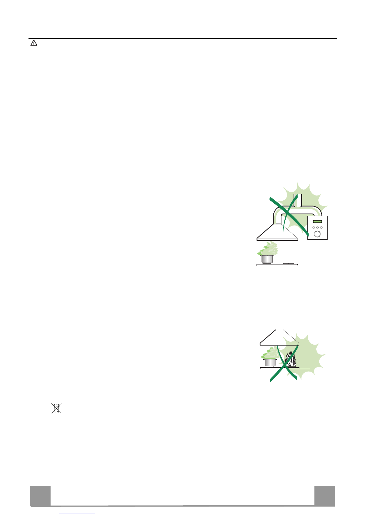
• Do not connect the extractor hood to exhaust ducts carrying combustion
fumes (boilers, fireplaces, etc.).
• If the extractor is used in conjuncti o n with non-electrical applianc es ( e.g. gas
burning ap pliances), a s ufficient degr ee of aeration m ust be guara nteed in
the room in or der to pr event the backflow of ex haust gas. The kit chen m ust
have an opening communicating directly with the open air in order to
guarantee the entry of clean air.
USE
• The extractor hood has been designed exclusively for domestic use to
eliminate kitchen smells.
• Never use the hood for purposes other than for which it has been designed.
• Never le a ve hi gh na ked fl a me s unde r the ho od wh en i t is in op er at ion .
• Adjust the flame intensity to dir ect it onto the bottom o f the pan only, m aki ng
sure that it does not engulf the sides.
• Deep fat f ryers must be c ontinuously monit ored during u se: overheated oil
can burst into flames.
• Do not flambè under the range hood; risk of fire
• This appli ance is not inten ded for use by pers ons (including c hildren) with
reduced phys ical, sensory or m ental capabi lities, or lack o f experience and
knowledge, unless they have been given supervision or instruction
concerning use of the appliance by a person responsible for their safety.
• Children should be supervised to ensure that they do not play with the
appliance.
MAINTENANCE
• Switch off or unplug the appliance fr om the m ai ns s up pl y be fo re ca rr yi n g ou t
any maintenance work.
• Clean and/or replace the Filters after the specified time period (Fire hazard).
• Clean the hood using a damp cloth and a neutral liquid detergent.
The symbol on the product or on its packaging indicates that this product may not be treated
as household waste. Instead it shall be handed over to the applicable collection point for the
recycli n g of electric al a nd electr o ni c eq uipment. By ensuri ng this pr o d uc t i s di s p osed of c orrectly,
you will help prevent potential negative consequences for the environment and human health,
which could otherwise be caused by inappropriate waste handling of this product. For more
detailed information about recycling of this product, please contact your local city office, your
household waste disposal service or the shop where you purchased the product.
EN
4
4
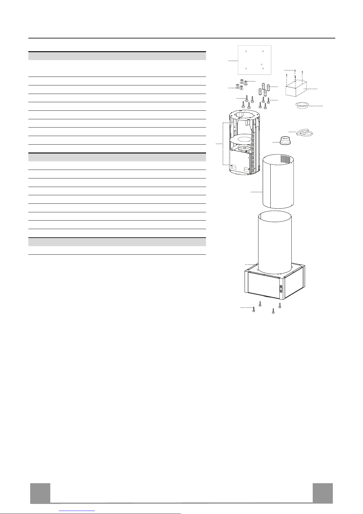
CHARACTERISTICS
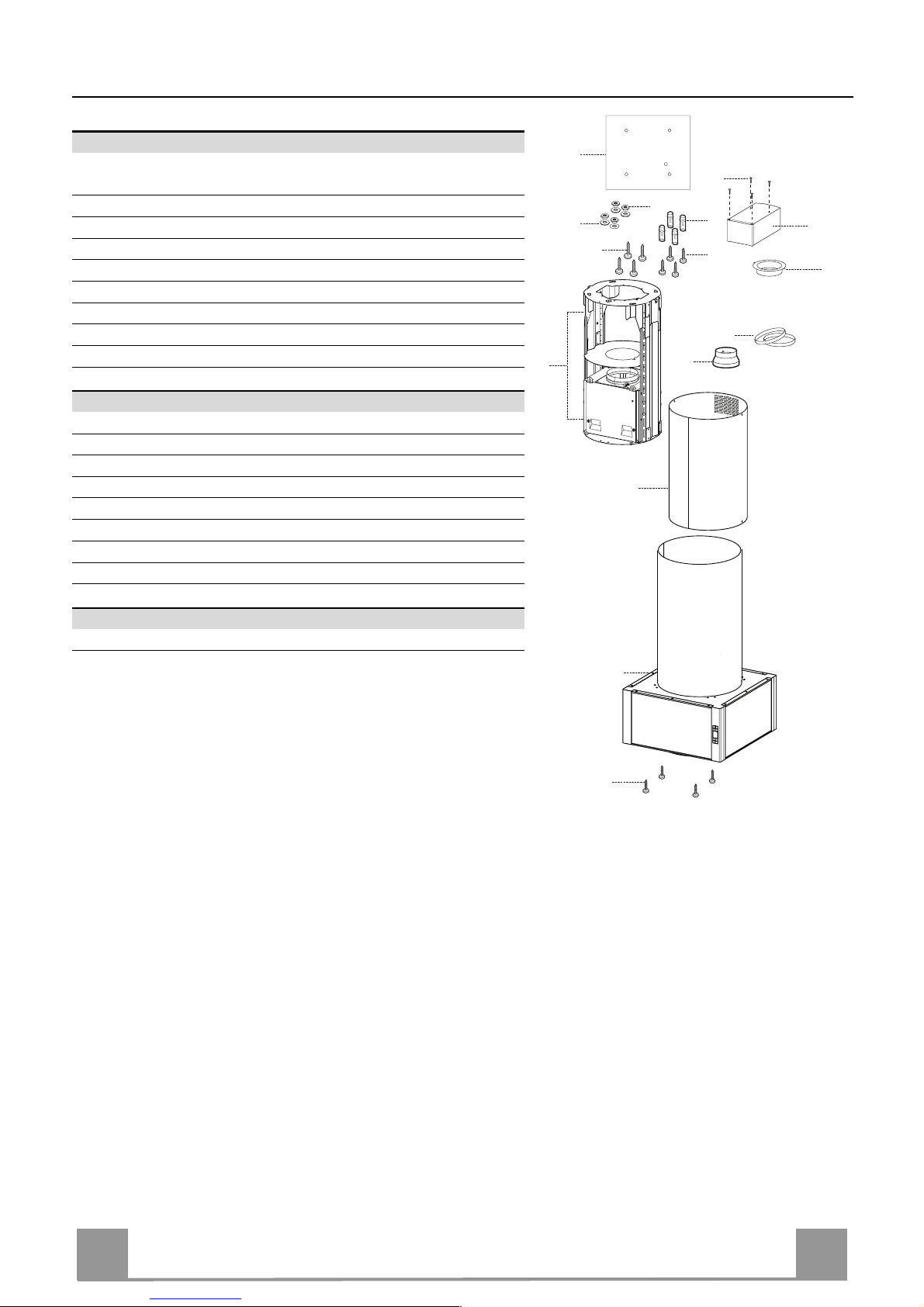
Components
Ref. Q.ty Product Components
1 1 Hood Body, complete with: Controls, Light, Blower,
Filters
2 1 Chimney Upper
7.1 1 Telescopi c frame complete with extractor , consisting of:
7.1a 1 Upper frame
7.1b 1 Lower frame
9 1 Reducer Fl ange ø 150-120 mm
10 1 Flange ø 120 mm
15 1 Recirculation Air Outlet Connection
25 Pipe clamps (not included)
Ref. Q.ty Installation Components
11 4 Wall Plugs ø 10
12c 4 Screws 2, 9 x 6,5
12f 4 Screws M6 x 10
12g 4 Screws M6 x 80
12h 4 Screws 5,2 x 70
21 1 Drilling template
22 4 6.4 mm int. dia washers
23 4 M6 nuts
Q.ty Documentation
1 Instruction Manual
2
11
12h
22
23
21
7.1
1
12g
9
25
7.1a
7.1b
15
12f
10
12c
EN
5
5
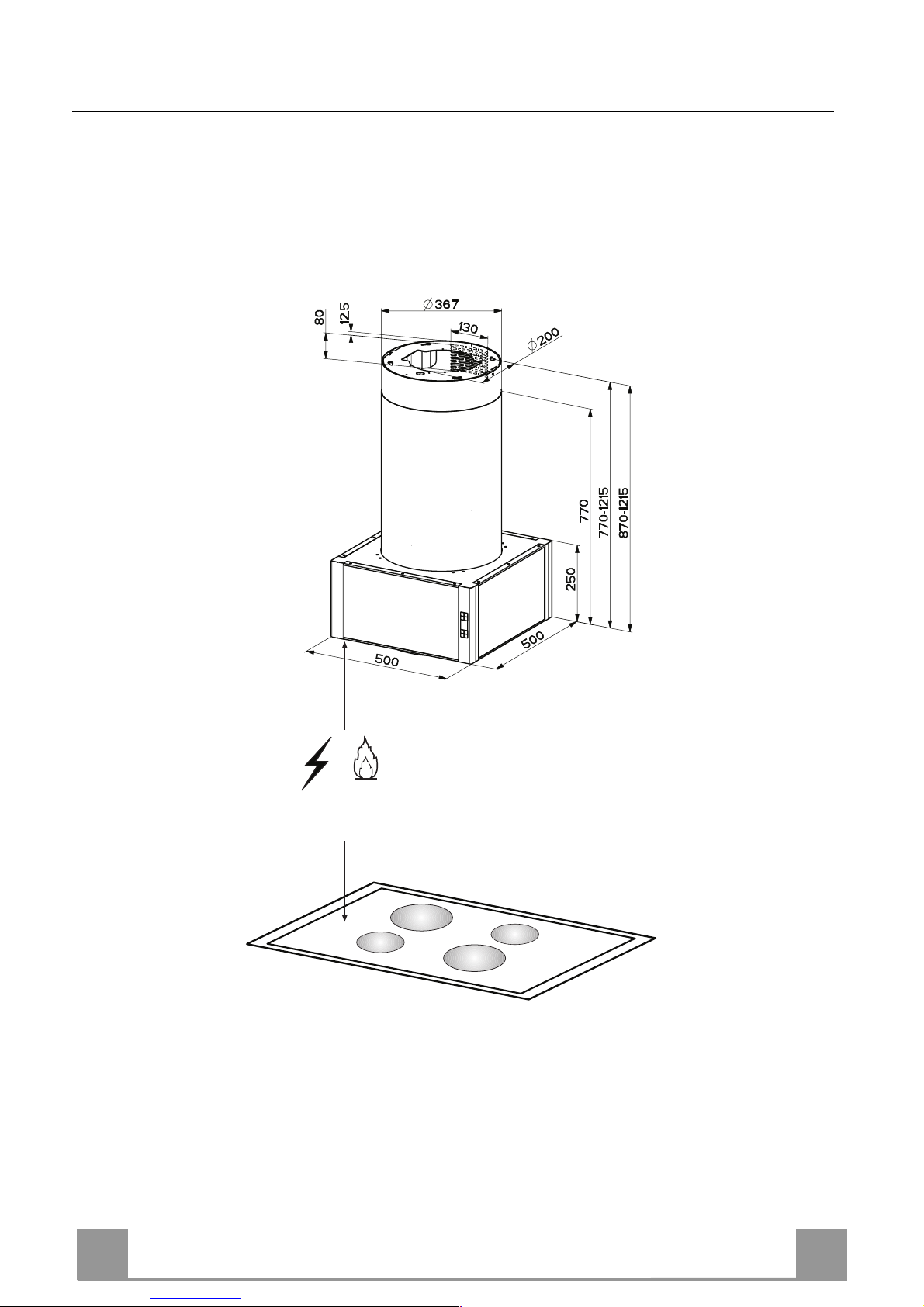
Dimensions
*
**
550 mm
* Dimensions of the hood in ducting version.
** Dimensions of the hood in recycling version.
EN
6
6
INSTALLATION
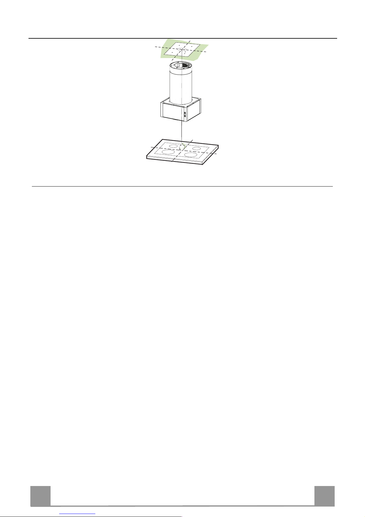
Drilling the Ceiling/shelf and fixing the frame
DRILLING THE CEILING/SHELF
• Use a plumb line to mark the centre of the hob on the ceiling/support shelf.
• Place the drilling template 21 provided on the ceiling/support shelf, making sure that the
template is in the correct position by lining up the axes of the template with those of the hob.
• Mark the centres of the holes in the template.
• Drill the holes at the points marked:
• For concrete ceilings, drill for plugs appropriate to the screw size.
• For hollow brick ceilings with wall thickness of 20 mm: drill ø 10 mm(immediately insert
the Dowels 11 supplied).
• For wooden beam ceilings, drill according to the wood screws used.
• For wooden shelf, drill ø 7 mm.
• For the power supply cable feed, drill ø 10 mm.
• For the air outlet (Duct ed Version), drill accord ing to the diameter of the extern al air exhaust duct connection.
• Insert two screws of the following type, crossing them and leaving 4-5 mm from the ceiling:
• For concrete ceilings, use the appropriate plugs for the screw size (not provided).
• for Cavity ceiling with inner space, with wall thickness of appro x. 20 mm, Screws 12h,
supplied.
• For wooden beam ceilings, use 4 wood screws (not provided).
• For wooden shelf, use 4 screws 12g with washers 22 and nuts 23, provided.

EN
7
7
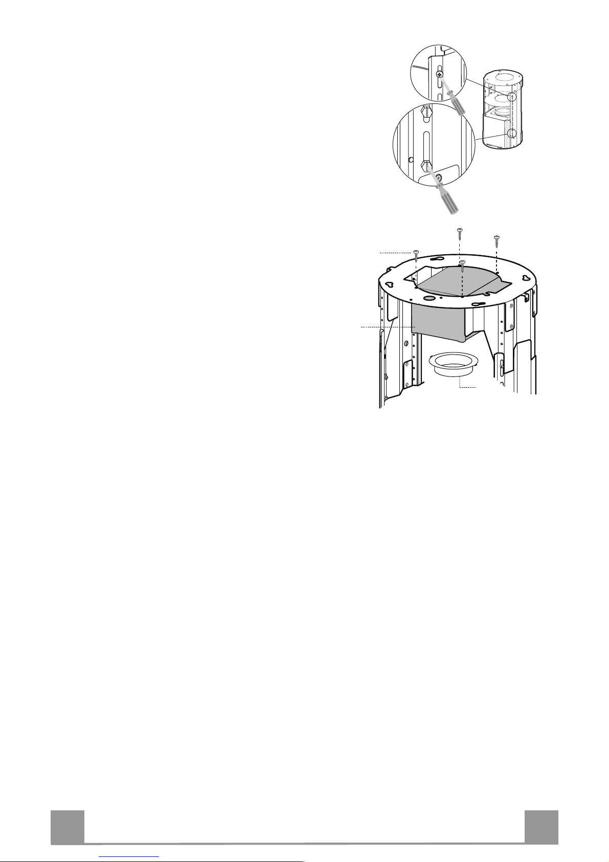
PREPARATION OF THE FRAME FOR THE HOOD IN RE-
CYCLING VERSION
In case the hood is used in recycling version it is necessary to prepare th e frame with al l th e necessar y co nn ection pieces. In or der to make the install ation easier it is
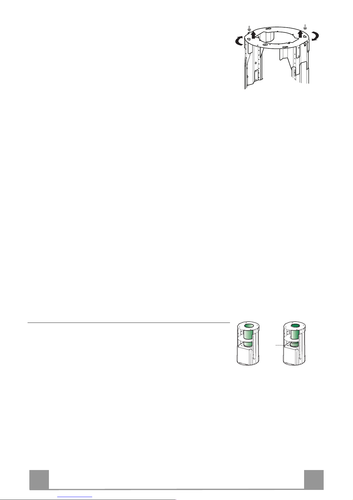
necessary to lengthen the frame:
• Unscrew the two screws 2.1 fixing the upper chim-
ney to the frame and pull the chimney out.
• Unscrew the four safety screws placed at the top in
the frame separation area. (A).
• Unscrew the eight metric screws connecting the two
columns, placed on both sides of the frame (B).
Installation of components in recycling version:
• Fix the recyclin g air ou tlet pi ece 15 to the upper part
of the frame using four 12c screws supplied with the
hood.
• Fix the flange (ø120) 10 to the lower part of the recycling air outlet 15.
• Put the reducer flange 9 on the hood body outlet.
• At this point, join the flanges with a pipe. In order to
calculate the height of the pipe it is necessary to estimate the height of the hood (mm) and subtract 615
mm. (H pipe = H hood-615).
• Lengthen the frame so that the pipe can be in serted.
Place the p ipe between the two flanges and block it.
Make sure that th e height of th e frame is correct con sidering the height of the cooker hood (H frame = H
hood – 184). Adjust the height of the frame and
tighten again the earlier removed screws. Tighten
again the safety screws in order to give more stability
to the structure.
• Fix the pipe with the pipe clamps 25 supplied with
the hood.
A
B
15
12c
10

EN
8
8
FIXING THE FRAME
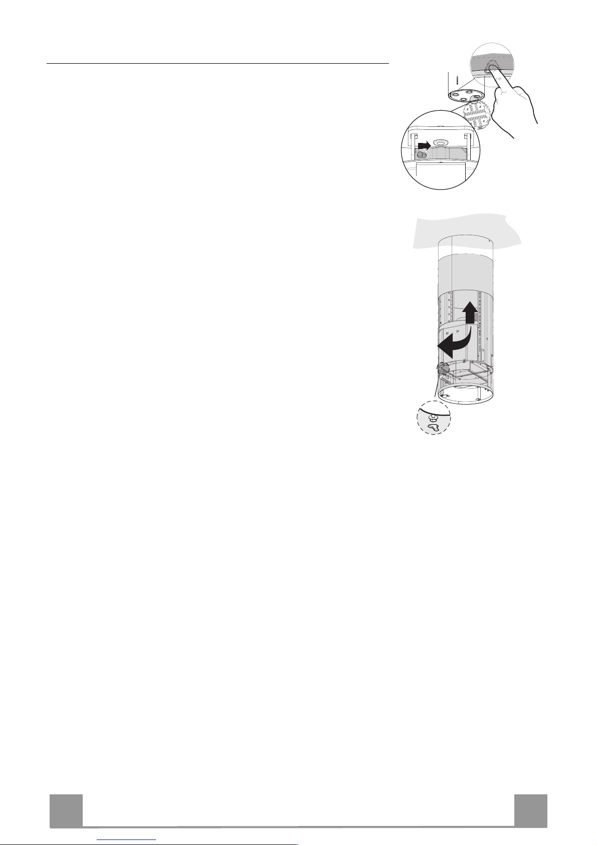
• Lift the frame up, making sure that the index over the frame
plate is turned forwards.
• Fit the frame slots onto the two screws inserted in the ceiling as
above, and turn until reaching the centre of the adjustment slot.
• Tighten the two screws and fasten the other two screws provided; before locking the screws completely, it is possible to
adjust the frame by turning it, making sure that the screws do
not come out of their housing in the adjustment slot.
• The Frame must be securely fastened so as to support both the
weight of the Hood and the stress caused by occasional axial
pressure against the fitted Appliance. After fixing, make sure
that the base i s stable even when t he Frame is sub jected to lateral stress.
• If the Ceiling is not strong enough in the area where the hood
is to be fixed, the Installer must strengthen the area using suitable plates and co unterplates anchored to resi stant structures.
2
1
1
2
Ducted version air exhaust system Connection
When installing the ducted version, connect the hood to the
chimney using either a flexible or rigid pipe ø 150 or 120 mm,
the choice of which is left to the installer.
• To install a ø 120 mm air exhaust connection, insert the reducer flange 9 on the hood body outlet.
• Fix the pipe using the pipe clamps 25 (not provided).
• Remove any activated charcoal filters.
9
ø 120ø 150

EN
9
9
Installing of the chimney and fixing of the hood
When the hood is installed in recycling version the chimney has
to be positioned with the slots upwards. When the hood is installed in ducting version it has to be positioned in the opposite
way.
• Place th e ch imney on th e frame a n d fix it to t he up p er part of it
with the earlier removed screws. When installing the hood in
recycling version make su re that the sl ots correspond to the air
outlet of the recycling air outlet piece 15.
• Open the lighting unit by slightly pulling the notch. Remove
the unit from the hood by sliding the fixing pivot.
• Remove the filter pushing it towards the back side of the hood
unit and simultaneously pulling downwards.
• Remove possible charcoal filters.
• In order to fix the hood body to the frame insert the 4 screws
12f in their seats. It is necessary to leave at least 4-5 mm gap
between the screw heads and the frame plate.
• Hook the hood canopy to the frame and turn it to the left until
it reaches the stop, then l ock the screws immediately to prevent
the hood canopy from falling out accidentally.
2
1

EN
110
ELECTRICAL CONNECTION
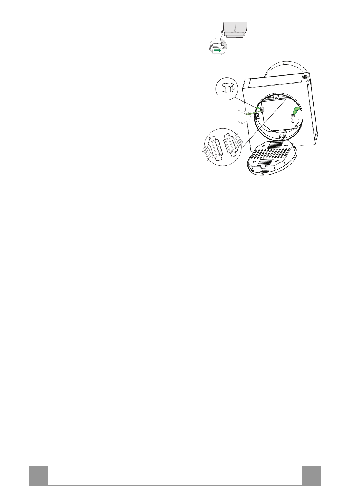
• Connect the Hood to the Mains power supply, inserting a two-pole switch with a contact gap of at least 3
mm.
• Make sure that the Power cable has been properly
inserted into the Suction fan socket.
• Fasten the commands connect or Cmd.
• Fasten the Overhead lights connector Lux to the
socket provided behind the lighting unit cover.
• From the inside, open the Cover of Neon terminal
box by removing the screws.
• Fasten the remaining free connector to the one provided in the Neon terminal box, then clo se the cover
and fix it in the predisposed place.
• For the recirculation version, fit the Activated charcoal odour filter.
• Replace the Grease filter and then the lighting unit.
Lux
Neon
Cmd
EN
111
USE
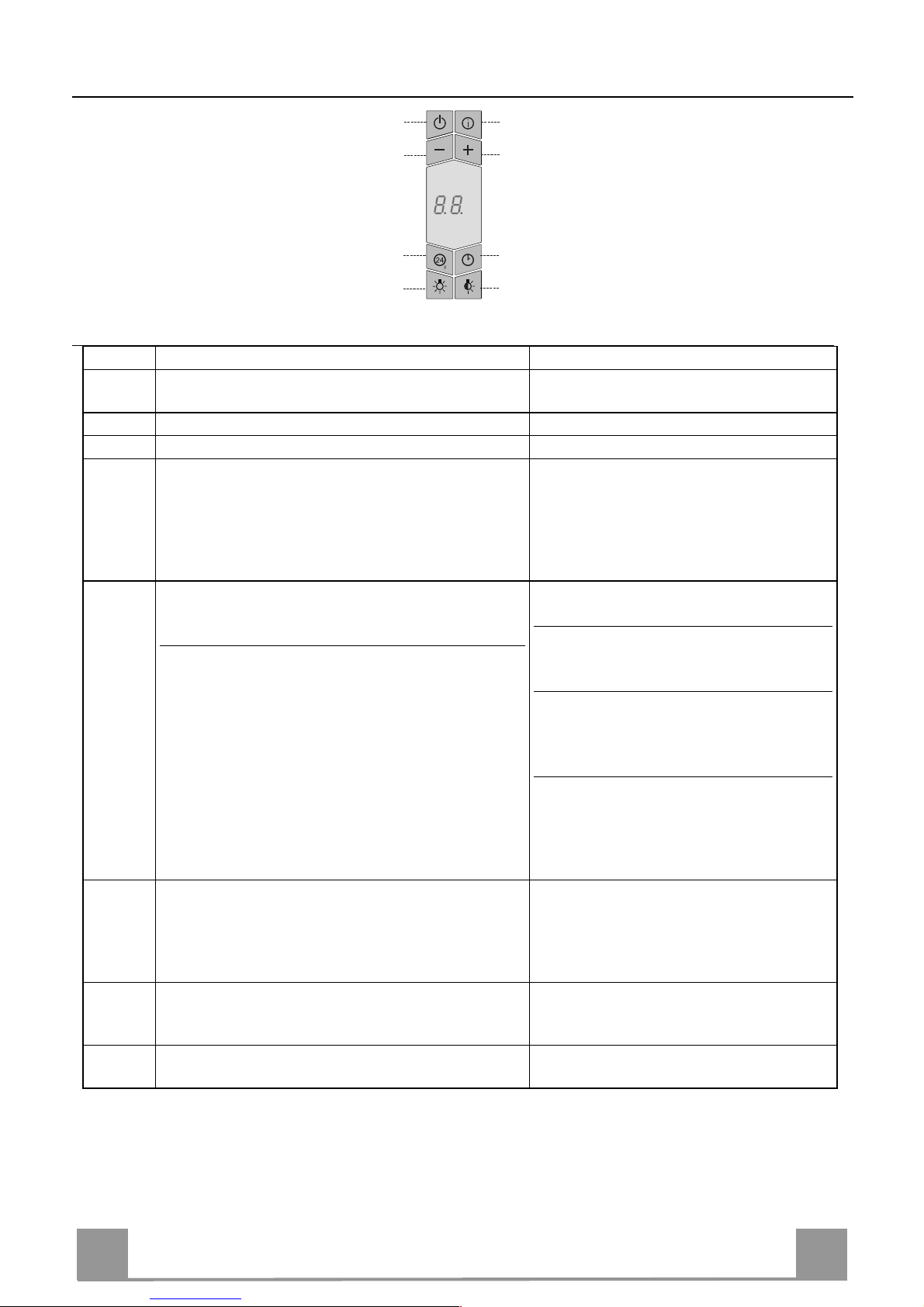
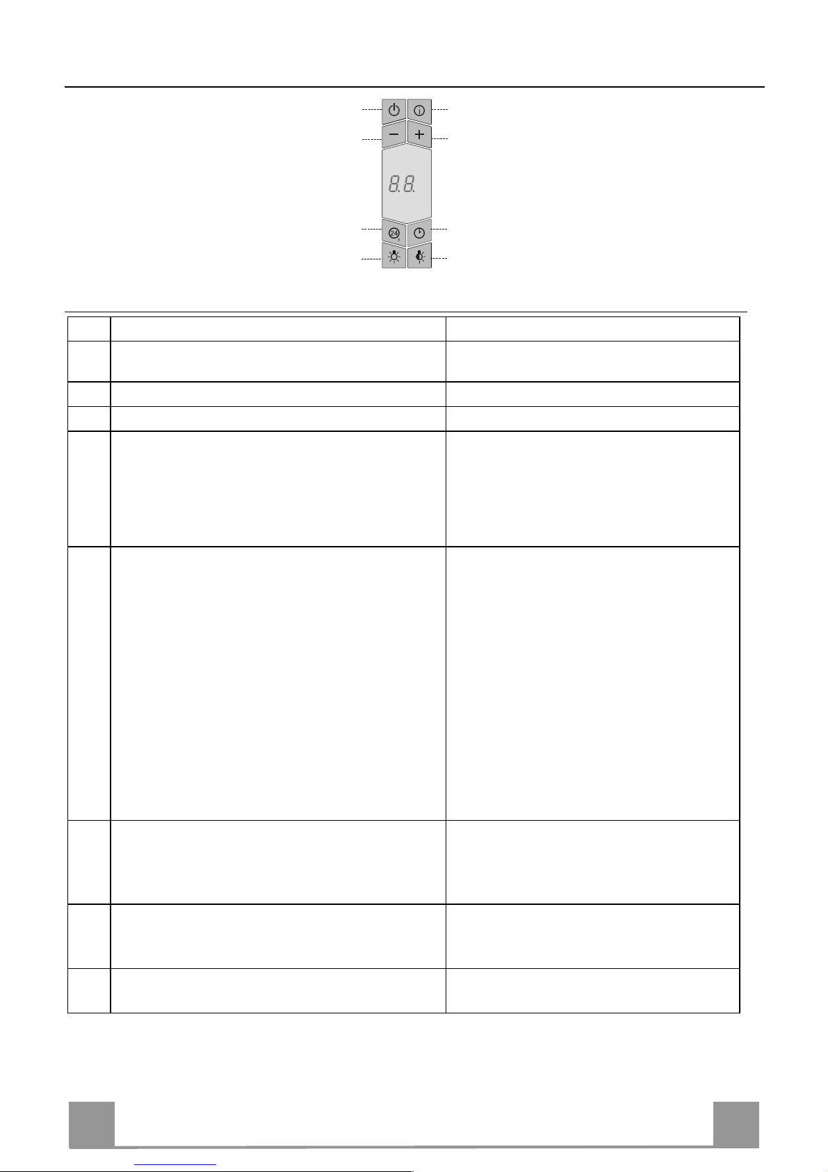
Control panel
Button Function Display
A Turns the suction motor on and off at the last
speed used.
Displays the speed setting
B Decreases the operating speed.
C Increases the operating speed .
D Activates intensive speed from any other speed,
even with the motor stopped. Intensive speed is
timed to run for 10 minutes, after which the system will return to the speed that was set previously. Suitable to deal with the highest level of
cooking fum es .
Displays HI and the spot at the bottom
right flash es once a second.
E Starts the motor at a speed that allows recircula-
tion of 100 m3/h for 10 minutes in every hour;
after which the motor stops.
When th e filters alarm is triggered, the a larm can
be reset by pressing and holding this button for
approximately 3 seconds. These indications are
only visible when the motor is turned off.
Displays 24 and the spot at the bottom
right flashes, while the motor is running.
When th e p roc edu re h a s b een c omp let ed ,
the indication previously displayed will
turn off:
FF indicat es the need to was h the metal
grease filters. The alarm is triggered after the Hood ha s been operating for 1 00
actual working hours.
EF indicat es th e need to c han ge th e ac ti -
vated charcoal filters, and also to wash
the metal grease filters. The alarm is
triggered a f ter the Hood has been operating for 200 actual working hours.
F
Activates automatic shutdown with a 30' delay.
Suitable to complete elimination of residual
odours. It ca n be activat ed from any pos ition, and
is deactivated by pressing the button or turning the
motor off.
Alternately displays the working speed
and the time remaining until the hood is
turned off. The spot at the bott om right
flashes.
G Turns the li ghti ng system (overhead sp otlight s) on
and off. If pressed and held for 2 seconds it turns
the side lights (Neon strips) on and off.
H Turns the low intensity lighting system (overhead
spotlights) on and off.
A
B
C
D
E
F
GH
EN
112
MAINTENANCE
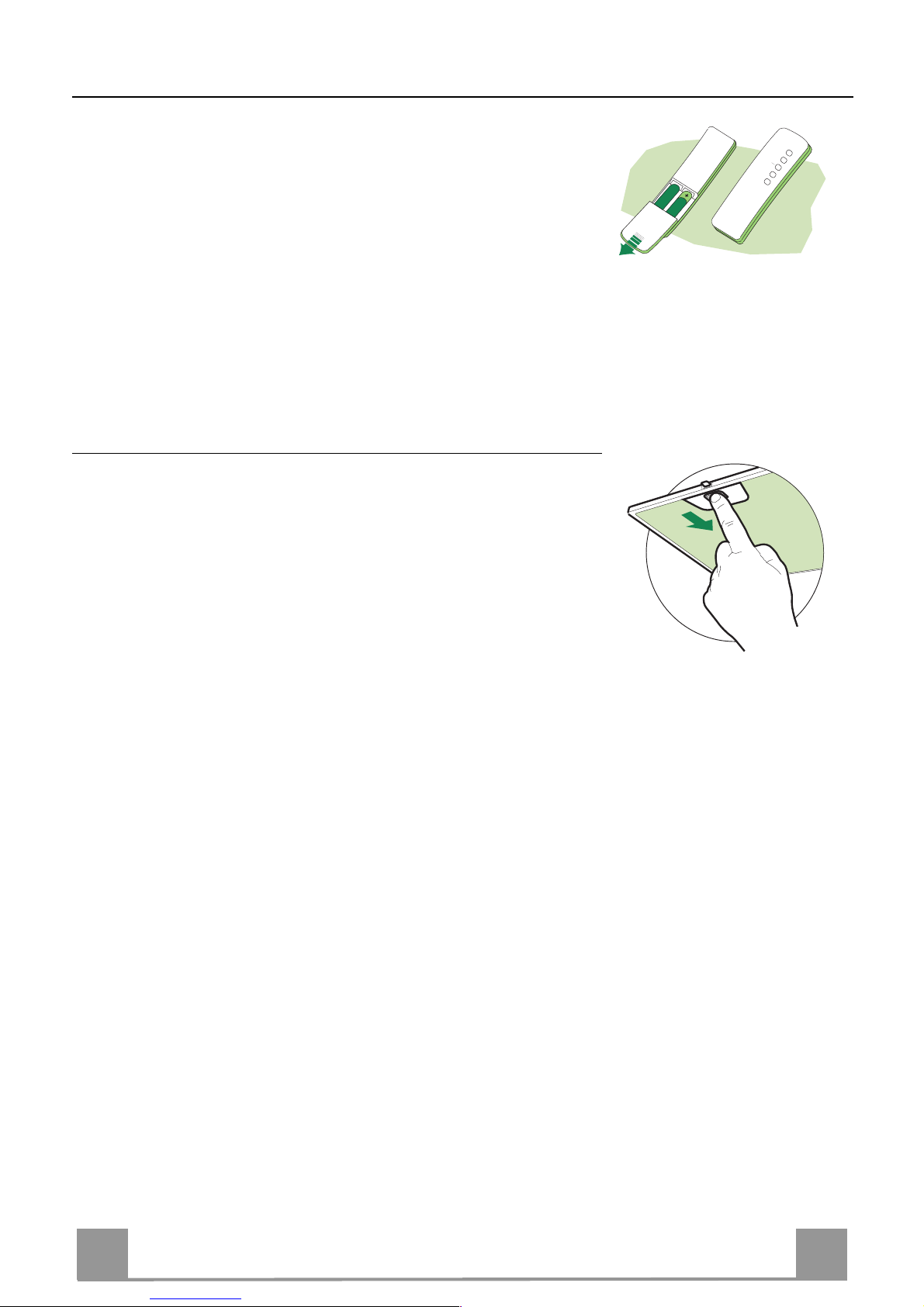
REMOTE CONTROL (OPTIONAL)
The appliance can be controlled using a remote control powered
by a 1.5 V carbon-zinc alkaline batteries of the standard LR03AAA type (not included).
• Do no t place the remote control near to heat sources.
• Used batteries must be disposed of in the proper manner.
Metal grease filters
Filters can be washed in the dish machine. They need to be
wash e d wh e n FF-sign appears on the display or in any case every
2 months, or even more frequently in case of particularly intensive use of the hood.
Alarm reset
• Switch off the hood and the lights. If the 24h-function has been
activated this has to be deactivated.
• Press the E-key till the display is unlit.
Cleaning the filters
• Open the lighting unit by pulling on the nocth.
• Remove the filters one by one pushing them towards the back
side of the hood unit and simultaneously pulling downwards.
• Any kind of bending of the filters has to be avoided when
washing them. Before fitting them again into the hood make
sure that they are completely dry. (The colour of the filter surface may change throughout the time but this has no influence
to the filter efficiency).
• When fitting the filters into the hood pay attention that they are
mounted in correct position the handle facing outwards.
• Replace t he lighting unit.

EN
113
Charcoal filter (recycling version)
• This filter cannot be washed or regenerated. It must be replaced when the EF app ears on t he
display or at least once every 4 months.
Activation of the alarm signal
• In the recycling version hoods the filter saturation alarm must be activated during the installation or later.
• Switch off the hood and the lights.
• Disconnect the hood from the mains supply.
• When restoring the connection press and hold B-key.
• When releasing the key two rotat in g rect angles appear on the display.
• Within 3 seconds press the B-key until a flashing confirmation appears on the dispaly:
• 2 flashes with EF - charcoal filter saturation alarm ACTIVATED
• 1 flash with EF - charcoal filter saturation alarm DEACTIVATED.
REPLACING THE CHARCOAL FILTER
Reset of the alarm signal
• Switch off the hood and the lighting. If the 24h-function has
been activated this has to be deactivated.
• Press the E-key until the display is unlit.
Replacing of the filter
• Open the lighting unit by pulling on the nocth.
• Remove the metal grease filters.
• Remove the saturated charcoal filter by releasing the fixing
hooks
• Fit the new filter and fasten it in its correct position.
• Put the metal grease filters in their seats.
• Replace t he lighting unit.

EN
114
Lighting
LIGHT REPLACEMENT
20 W halogen light.
• Extract the lamp from the lamp holder by pulling
gently.
• Replace with ano ther of the same type, making sure
that the two pins are properly inserted in the lamp
holder socket holes.
Lighting
CHANGING LAMPS
9 W Neon Lamp
• Unfasten the screws and remove the metal glass fixing element, making sure you do not drop it.
• Remove the Glass.
• Replace the neon lamp from the inside, pulling it
downwards and fitting a new one with the same characteristics.
• To reassemble, repeat t he ab o ve o perati ons in reverse
order.
IT 115
CONSIGLI E SUGGERIMENTI
Questo libretto di istruzioni per l'uso è previsto per più versioni dell' appare
c
chio.
É possibile che siano descritti singoli particolari della dotazione, che non
riguardano il Vos tr o apparec c hio.
INSTALLAZI ONE
• Il produttore declina qualsiasi responsabilità per danni dovuti ad installazione non
corretta o non c onf orme alle r egole dell’art e.
• La distanza minima di sicurezza tra il Piano di cottura e la Cappa deve essere di
650 mm, (alcuni modelli possono essere installati ad un’altezza inferiore, fare
riferiment o ai par agraf i i ngombro e i ns tal laz ione) .
• Verificare che la tensione di rete corrisponda a quella riportata nella targhetta
posta all’interno della Cappa.
• Per Apparecchi in Classe I
a
accertarsi che l’impianto elettrico domestico
garantisc a un cor ret t o scar ico a t er ra.
• Collegare la Cappa all’uscita dell’aria aspirata con tubazione di diametro pari o
superiore a 120 mm. Il percorso della tubazione deve essere il più breve
possibile.
• Non collegare la Cappa a condotti di scarico dei fumi prodotti da combustione
(caldaie, c ami nett i, ec c. ).
• Nel caso in cui nella stanza vengano utilizzati sia la Cappa che apparecchi non
azionati da energia elettrica (ad esempio apparecchi utilizzatori di gas), si deve
provvedere ad una aerazione sufficiente dell’ambiente. Se la cucina ne fosse
sprovvista, praticare un’apertura che comunichi con l’esterno, per garantire il
richiamo d’ar ia pul it a.
USO
• La Cappa è stata progettata esclusivamente per uso domestico, per abbattere gli
odori della cuc ina.
• Non fare mai uso impropri o dell a Cap pa.
• Non lasciare fiamme li bere a f ort e int ens it à sott o la Cappa i n funz ione.
• Regolare sempre le fiamme in modo da evitare una evidente fuoriuscita laterale
delle stes se ri s pett o al fondo del le p ent ole.
• Controllare le fri ggit ric i durante l ’us o: l’ oli o surri scal dato pot r ebbe i nf iammar si .
• Non preparare aliment i f lambè s ott o l a cappa da c uc ina; peri c olo d'i ncen di o.
• Questo apparecch io non de ve essere utilizza to da pe rsone (ba mbini in clusi) con
ridotte capacità psichiche, sensoriali o mentali, oppure da persone senza
esperienza e conoscenza, a meno che non siano controllati o istruiti all’uso
dell’apparecchio da per son e r es ponsabili d ella loro sicurezza.
• I bambini devono essere supervisionati per assicurarsi che non giochino con
l’apparecchi o.
MANUTENZIONE
• Prima di procedere a qualsiasi operazione di manutenzione, disinserire la Cappa
togliendo la spina elettric a o s pegnendo l’interruttore generale.
• Effettuare una scrupolosa e tempestiva manutenzione dei Filtri secondo gli
intervall i cons i gli ati ( Risc hi o di inc endio) .
• Per la pulizia d e lle su pe rfici d e lla Ca pp a è suffi cie n te u tiliz za re u n pann o umido e
detersiv o li quido neut ro.
Il simbolo sul prodotto o sulla conf ezione indica che il prodotto non deve essere considerato
come un no r m ale rifi ut o domesti c o , ma deve es sere por ta to nel pu nt o di raccolta appro pr iato per
il riciclaggio di apparecchiature elettriche ed elettroniche. Provvedendo a smaltire questo
prodotto in modo appropriato, si contribuisce a evitare potenziali conseguenze negative per
l’ambiente e per la salute, che potrebbero derivare da uno smaltimento inadeguato del prodotto.
Per inf ormaz ioni più dett agli ate s ul ric icla ggio di q uest o pro dott o, co ntat tare l ’uffi cio comu nale , il
servizio locale di smaltimen to rif iuti o il negoz io in cui è stato acquista to il prodo tto .
IT 116
CARATTERISTICHE
Componenti
Rif. Q.tà Componenti di Prodotto
1 1 Corpo Cappa com pleto di : Comandi, Lu ce, Filtri, Ca mi-
no Inferiore
2 1 Camino superiore
7.1 1 Traliccio telescopico completo di Aspiratore,formato da:
7.1a 1 Traliccio superiore
7.1b 1 Traliccio inferiore
9 1 Flangia di riduzione ø 150-120 mm
10 1 Flangia ø 120 mm
15 1 Raccordo Uscita Aria Filtrante
25 Fascette st ringitubo (non incluse)
Rif. Q.tà Componenti di Installazione
11 4 Tasselli ø 10
12c 4 Viti 2,9 x 6,5
12f 4 Viti M6 x 15
12g 4 Viti M6 x 80
12h 4 Viti 5,2 x 70
21 1 Dima di foratura
22 4 Rondelle ø 6,4
23 4 Dadi M6
Q.tà Documentazione
1 Libretto Istruzioni
2
11
12h
22
23
21
7.1
1
12g
9
25
7.1a
7.1b
15
12f
10
12c

IT 117
Ingombro
*
**
550 mm
* Dimensioni per cappa in versione aspirante.
** Dimensioni per cappa in versione filtrante.

IT 118
INSTALLAZIONE
6
Foratura Soffitto/Mensola e Fissaggio Traliccio
FORATURA SOFFITTO/MENSOLA
• Con l’ausilio di un Filo a piombo riportare sul Soffitto/Mensola di supporto il centro del
Piano di Cottura.
• Appoggiare al Soffitto/Mensola la Dima di Foratura 21 in dotazione, facendo coincidere il
suo centro al centro proiettato e allineando gli assi della Dima agli assi del Piano di Cottura.
• Segnare i centri dei Fori della Dima.
• Forare i punti seguenti:
• Soffitto in Calcestruzzo massiccio: secondo Tasselli per Calcestruzzo impiegati.
• Soffitto in Laterizio a camera d’aria, con spessore resistente di 20 mm: ø 10 mm (inserire
subito i Tasselli 11 in do ta z ione ) .
• Soffitto in Travatura di Legno: secondo Viti per Legno impiegate.
• Mensola in Legno: ø 7 mm.
• Passaggio del Cavo elettrico di Alimentazione: ø 10 mm.
• Uscita Aria (Versione Aspirante): secondo diametro del collegamento alla Tubazione di
Evacuazione Esterna.
• Avvitare, incrociandole e lasciando 4-5 mm dal soffitto, due viti:
• per Calcestruzzo massiccio, Tasselli per Calcestruzzo, non in dotazione.
• per Laterizio a ca mera d’aria, co n spesso re resistent e di 20 mm circa, Viti 12h, in dotazio-
ne.
• per Travatura di legno, Viti per legno, non in dotazione.
• per Mensola in Legno, viti 12g con Rondelle 22 e Dadi 23, in dotazione.
IT 119
PREPARAZIONE DEL TRALICCIO PER LA CONNESIONE
FILTRANTE
Nel caso in cui si installi la cappa in versione filtrante
bisogna predisporre nel traliccio tutti i raccordi necessari per tale versione. Per facilitare l’installazione dei particolari per la versione filtrante è necessario allungare il
traliccio, procedere come segue:
• Svitare le due viti che fissano il camino superiore 2.1
al traliccio e sfilare il camino.
• Svitare le quattro viti di sicurezza poste in alto nella
zona di separazione del traliccio. (A)
• Svitare le otto viti metriche che uniscono le due co-
lonne, poste ai lati del traliccio. (B)
Installazione dei componenti per versione filtrante:
• Fissare il raccordo filtrante 15 alla parte superiore del
traliccio utilizzando le 4 viti 12c in dotazione.
• Agganciare con movimento rotativo la flangia (ø120)
10 alla parte inferiore del raccordo filtrante 15.
• Inserire la flangia di riduzione 9 sull’uscita dell’aspiratore.
• A questo punto bisogna collegare le due flangie con
un tubo, per calcolare l’altezza del tubo occorre stimare l’altezza della cappa (mm) e sottrarre 615 mm.
(H tubo = H cappa-615).
• Allungare il traliccio tanto da permettere l’inserimento del tubo e riposizionarlo bloccando il tubo tra
le due flangie. Verificare se l’altezza del traliccio è
adeguata all’altezza desiderata della cappa (H traliccio = H cappa – 184). Regolare l’altezza desiderata
del traliccio e riavvitare le viti precedentemente tolte.
Per garantire una maggiore stabilità al traliccio riavvitare le quattro viti di sicurezza sull’ultimo foro disponibile.
• Fissare il tubo con le fascette stringitubo 25 in dotazione.
A
B
15
12c
10
IT 220
FISSAGGIO TRALICCIO
• Sollevare il traliccio facendo attenzione che l’indice posto sopra la piastra del tral iccio sia nella parte anteriore.
• Incastrare le asole del traliccio sulle d ue viti predisposte precedentemente al soffitto e ruotare fino al centro dell’asola di regolazione.
• Stringere le due viti e avvitare le altre due in dotazione; prima
di serrare definitivamente le viti è possibile effettuare delle regolazioni ruotando il traliccio, facendo attenzione che le viti
non escano dalla sede dell’asola di regolazione.
• Il fissaggio del Traliccio deve essere sicu ro in relazione sia al
peso della Cappa sia alle sollecitazioni causate da occasionali
spinte laterali all’Apparecchio montato. A fissaggio avvenuto
verificare quind i che la base sia stabile anch e se il Traliccio è
sollecitato a flessione.
• In tutti i casi in cui il Soffitto non fosse sufficientemente robusto sul punto di sospensione, l’Installatore dovrà provvedere a
irrobustirlo con opportune piastre e contropiastre ancorate a
parti strutturalmente resistenti.
2
1
1
2
Connessione Uscita aria Versione Aspirante
Per installazione in Versione Aspirante collegare la Cappa alla
tubazione di uscita per mezzo di un tubo rigido o flessibile di
ø 150 o 120 mm, la cui scelta è lasciata all’installatore.
• Per collegamento con tubo ø 120 mm, inserire la Flangia di
riduzione 9 sull’Uscita del Corpo Cappa.
• Fissare il tubo con adeguate fascette stri ng itubo 25(non incluse).
• Rimuovere eventuali filtri al carbone attivo.
9
ø 120ø 150
IT 221
Montaggio Camino e Fissaggio Corpo Cappa
Il camino va girato con le asole verso l’alto in caso di installazi one della cappa in versione filtrante, viceversa con le asole verso il
basso in caso di installazione in versione aspirante.
• Infilare dal basso verso l’alto il Camino superiore e fissarlo
nella parte sup eriore al Tralicci o co n 2 Viti t olte in preced enza,
prestando attenzione nel caso di installazione filtrante che le
asole del camino sia in corrispo ndenza dell’ uscita del racco rdo
filtrante 15.
• Aprire il gruppo illuminazione tirandolo sull’apposita intacca,
sganciarlo dal corpo cappa facendo scorrere l’apposito perno di
fissaggio.
• Togliere il Filtro Antigrasso, spingendolo verso la parte posteriore del gruppo e tirando contemporaneamente verso il basso.
• Togliere eventuali Filtri Antiodore al Carbone attivo.
• Predisporre il fissaggio del corpo cappa al traliccio avvitando
le 4 Viti 12f nelle apposite sedi.Lasciare almeno 4-5 mm di
spazio tra la testa della vite e la piastra del traliccio.
• Agganciare il corpo cappa al traliccio e ruotare verso sinistra
fino alla batt uta, procedere immediatamente al bloccaggio delle
viti così da evitare un’accidentale caduta del corpo cappa.
2
1
IT 222
CONNESSIONE ELETTRICA
• Collegare la Cappa all’Alimentazione di Rete interponendo un Interruttore bipolare con apertura dei
contatti di almeno 3 mm.
• Assicurarsi che il connettore del Cavo alimentazione
sia correttamente inserito nella presa dell’Aspiratore.
• Collegare il connettore dei Comandi Cmd.
• Collegare il connettore dei Faretti Lux alla presa predisposta dietro al coperchio del gruppo illuminazione.
• Dall’int erno, apri re il coperch io della Scato la co nnessione elettrica Neon svitando le Viti.
• Collegare il Connettore rimasto libero a quello già
presente nella Scatola connessione Neon, richiudere
il coperchio e montare la Scatola nel posto predisposto.
• P er la Versione Filtrante montare il Filtro Antiodore
al Carbone attivo.
• Rimontare il Filtro Antigrasso e successivamente il
gruppo illuminazione.
Lux
Neon
Cmd
IT 223
USO
Quadro comandi
Tasto Funzione Display
A
Accende e spegne il motore di aspirazione
all’ultima velocità utilizzata.
Visualizza la velocità impostata
B Decrementa la velocità di esercizio.
C Incrementa la velocità di esercizio.
D
Attiva la velocità intensiva da qualsiasi velocità
anche da motore spento, tale velocità è temporizzata a 10 minuti, al termine del tempo il sistema
ritorna alla velocità precedentemente impostata.
Adatta a fronteggiare le m assime emis sioni di fumi di cottura .
Visualizza HI e il pun to in basso a destra
lampeggia una volta al secondo.
E
Attiva il motore ad una velocità che consente
un’aspirazione di 100 m
3
/h per 10 minuti ogn i ora,
terminati il motore si ferma.
Con l’allarme filtri in corso premendo il t asto per
circa 3 secondi si effettua il reset dell’al-larme.
Tali segnalazioni sono visibili solo a motore spento.
Visualizza 24 e il punto in basso a destra
lampeggia, mentre il motore è in funzione
Terminata la procedura si spegne la segnalazione precedentemente visu alizzata:
FF segnala la necessità di lavare i filtri
antigrasso metallici. L’allarme entra
in funzione dopo 100 ore di lavoro effettivo della Cappa.
EF segnala la necessità di sostituire i filtri
al carbone attivo e devono anche essere lavat i i filtri antigrass o metallici.
L’allarme en tra in fun zione dopo 200
ore di lavoro eff ettivo della C appa.
F
Attiva lo spegnimento automatico ritardato di 30’.
Adatto per completare l’eliminazione di odori
residui. Attivabile da qualsiasi posizione, si disattiva premendo il tasto o spegnendo il motore.
Visualizza alternativamente la velocità di
esercizi o e il tempo rimanente allo spegnimento della cappa. Il punto in basso a destra lampeggia.
G
Accende e spegne l’impianto di illuminazione
(Faretti). Tenendolo premuto per 2 secondi accende e spegn e l’ illumin azione laterale (Neon).
H
Accende e spegne l’impianto di illuminazione ad
intensità ridotta (Faretti).
A
B
C
D
E
F
GH
 Loading...