

Page 1

Istruzioni per l’uso e l’installazione
Cappa
Instructions for use and installation
Cooker Hood
Mode d’emploi et installation
Hotte de Cuisine
Bedienungsanleitung und Einrichtung
Dunstabzugshaube
Kullan
ım ve montaj talimatları
Davlumbaz
FGL 904 I
IT
GB
FR
DE
TR
Page 2

IT
2
2
Libretto di Istruzioni
INDICE
CONSIGLI E SUGGERIMENTI ..............................................................................................................................................7
CARATTERISTICHE..............................................................................................................................................................8
INSTALLAZIONE..................................................................................................................................................................10
USO......................................................................................................................................................................................13
MANUTENZIONE.................................................................................................................................................................14
Page 3

EN
3
3
Instructions Manual
INDEX
RECOMMENDATIONS AND SUGGESTIONS....................................................................................................................15
CHARACTERISTICS............................................................................................................................................................16
INSTALLATION ....................................................................................................................................................................18
USE.......................................................................................................................................................................................21
MAINTENANCE....................................................................................................................................................................22
Page 4

FR
4
4
Manuel d’Instructions
SOMMAIRE
CONSEILS ET SUGGESTIONS ..........................................................................................................................................23
CARACTERISTIQUES.........................................................................................................................................................24
INSTALLATION ....................................................................................................................................................................26
UTILISATION........................................................................................................................................................................29
ENTRETIEN..........................................................................................................................................................................30
Page 5

DE
5
5
Bedienungsanleitung
INHALTSVERZEICHNIS
EMPFEHLUNGEN UND HINWEISE....................................................................................................................................31
CHARAKTERISTIKEN..........................................................................................................................................................32
MONTAGE............................................................................................................................................................................34
BEDIENUNG.........................................................................................................................................................................37
WARTUNG............................................................................................................................................................................38
Page 6

TR
6
6
Kullanim Kilavuku
IÇERIKLER
TAVSIYELER VE ÖNERILER ..............................................................................................................................................39
ÖZELLIKLER........................................................................................................................................................................40
MONTAJ...............................................................................................................................................................................42
KULLANIM............................................................................................................................................................................45
BAKIM...................................................................................................................................................................................46
Page 7
IT
7
7
CONSIGLI E SUGGERIMENTI
INSTALLAZIONE
• Il produttore declina qualsiasi responsabilità per danni dovuti
ad installazione non corretta o non conforme alle regole
dell’arte.
• La distanza minima di sicurezza tra il Piano di cottura e la
Cappa deve essere di 650 mm.
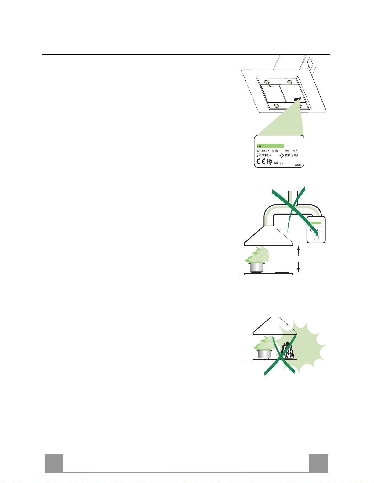
• Verificare che la tensione di rete corrisponda a quella riportata
nella targhetta posta all’interno della Cappa.
• Per Apparecchi in Classe Ia accertarsi che l’impianto elettrico
domestico garantisca un corretto scarico a terra.
• Collegare la Cappa all’uscita dell’aria aspirata con tubazione di
diametro pari o superiore a 120 mm. Il percorso della tubazione deve essere il più breve possibile.
• Non collegare la Cappa a condotti di scarico dei fumi prodotti
da combustione (caldaie, caminetti, ecc.).
• Nel caso in cui nella stanza vengano utilizzati sia la Cappa che
apparecchi non azionati da energia elettrica (ad esempio apparecchi utilizzatori di gas), si deve provvedere ad una aerazione
sufficiente dell’ambiente. Se la cucina ne fosse sprovvista, praticare un’apertura che comunichi con l’esterno, per garantire il
richiamo d’aria pulita.
USO
• La Cappa è stata progettata esclusivamente per uso domestico,
per abbattere gli odori della cucina.
• Non fare mai uso improprio della Cappa.
• Non lasciare fiamme libere a forte intensità sotto la Cappa in
funzione.
• Regolare sempre le fiamme in modo da evitare una evidente
fuoriuscita laterale delle stesse rispetto al fondo delle pentole.
• Controllare le friggitrici durante l’uso: l’olio surriscaldato potrebbe infiammarsi.
• La Cappa non deve essere utilizzata da bambini o persone non
abilitate all’uso corretto.
MANUTENZIONE
• Prima di procedere a qualsiasi operazione di manutenzione,
disinserire la Cappa togliendo la spina elettrica o spegnendo
l’interruttore generale.
• Effettuare una scrupolosa e tempestiva manutenzione dei Filtri
secondo gli intervalli consigliati.
• Per la pulizia delle superfici della Cappa è sufficiente utilizzare
un panno umido e detersivo liquido neutro.
650 mm min.
Page 8
IT
8
8
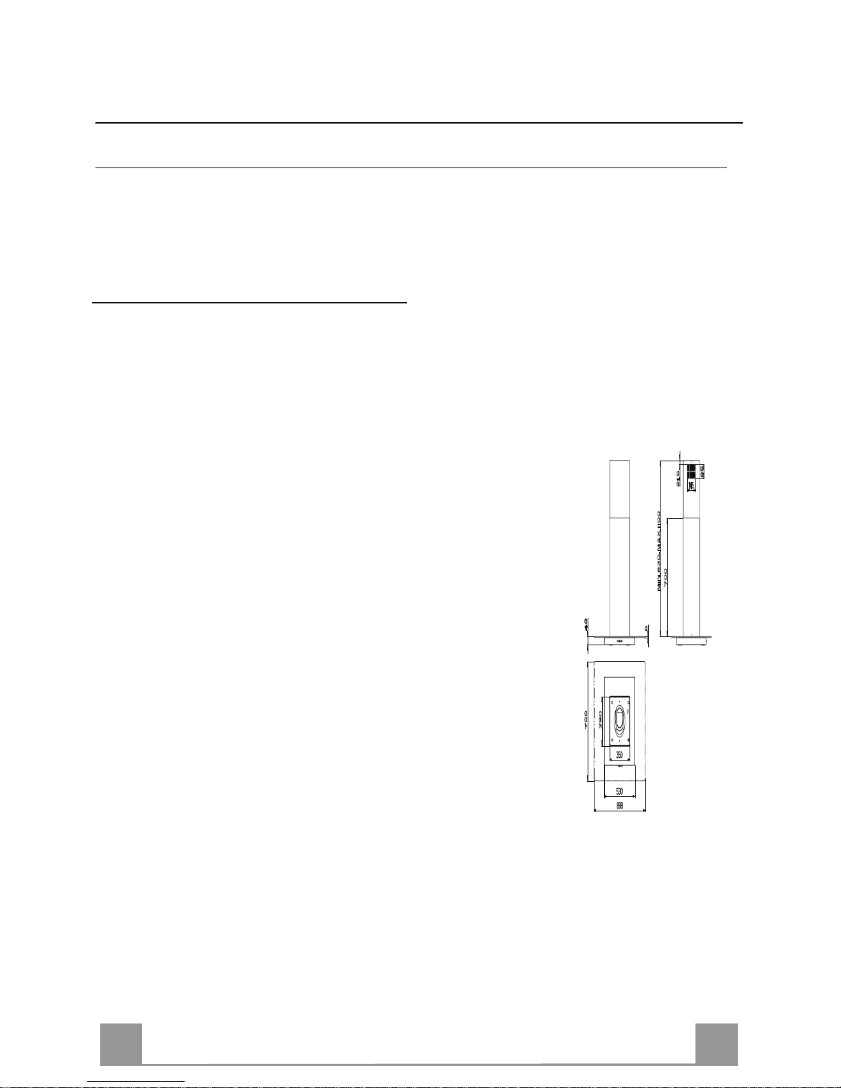
CARATTERISTICHE
Ingombro
Page 9
IT
9
9
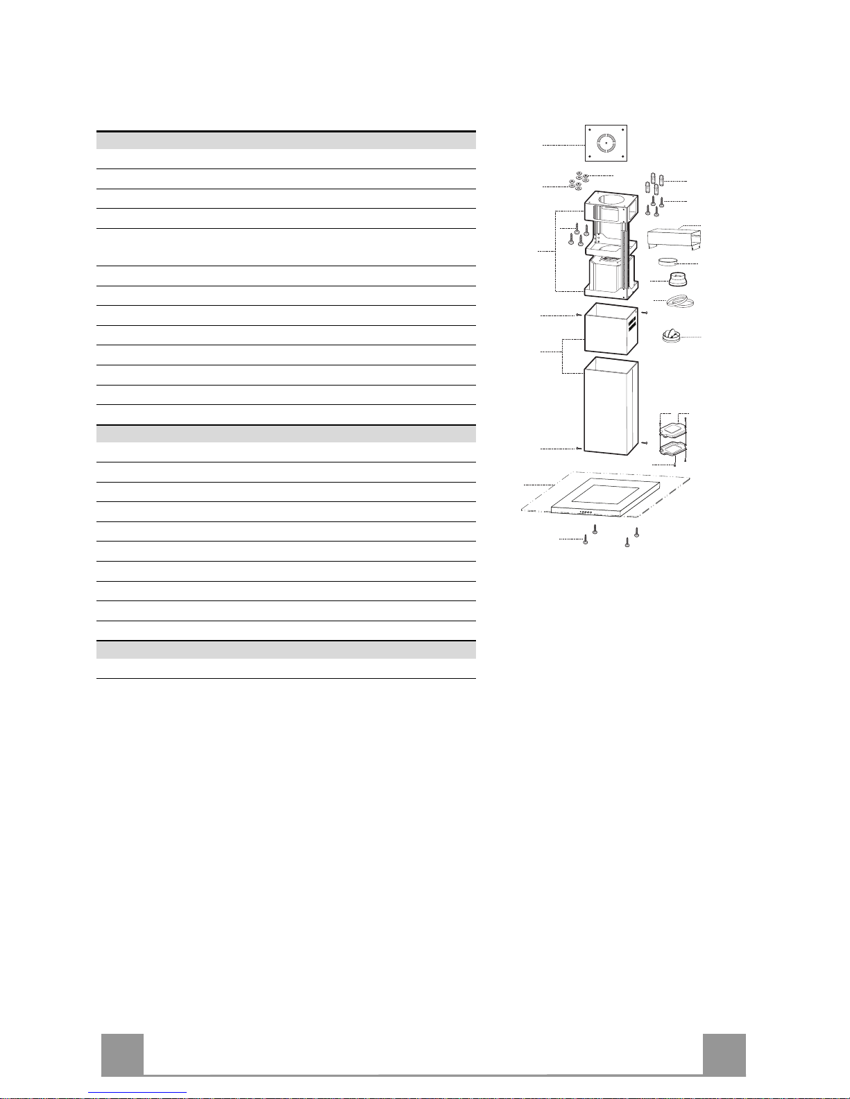
Componenti
Rif. Q.tà Componenti di Prodotto
1 1 Corpo Cappa completo di: Comandi, Luce , Filtri
2 1 Camino telescopico formato da:
2.1 1 Camino superiore
2.2 1 Camino inferiore
7.1 1 Traliccio telescopico completo di Aspiratore, formato
da:
7.1a 1 Traliccio superiore
7.1b 1 Traliccio inferiore
10 1 Flangia ø 150
10a 1 Flangia con v alvola ø 150 mm
15 1 Raccordo Uscita Aria
24 1 Scatola connessioni
25 2 Fascette stringitubo
Rif. Q.tà Componenti di Installazione
11 4 Tasselli ø 10
12c 6 Viti 2,9 x 6,5
12e 2 Viti 2,9 x 9,5
12f 4 Viti M6 x 10
12g 4 Viti M6 x 80
12h 4 Viti 5,2 x 70
21 1 Dima di foratura
22 4 Rondelle øi 6,4
23 4 Dadi M6
Q.tà Documentazione
1 Libretto I struzioni
12c
7.1a
7.1
22
23
12h
7.1b
2
2.1
2.2
12c
11
21
12g
24
12e
15
12c
25
9
10
12f
1
9
10a
Page 10
IT 110
INSTALLAZIONE
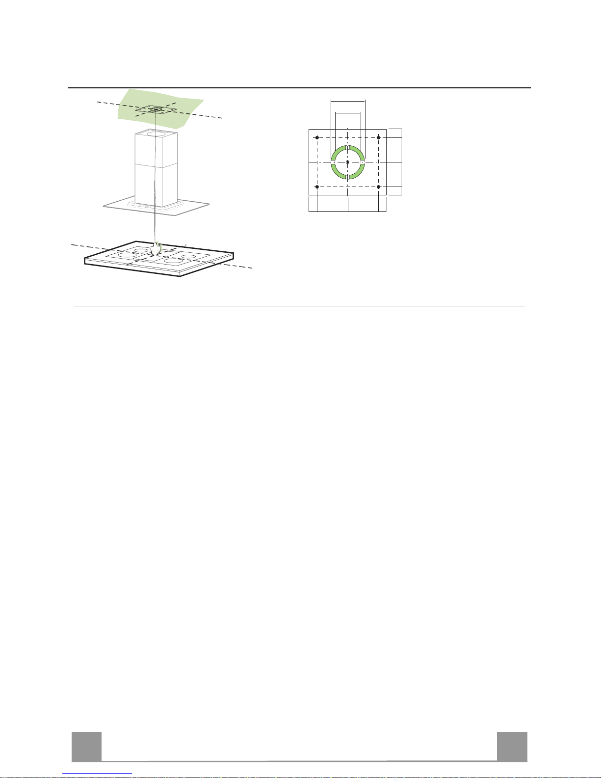
Foratura Soffitto/Mensola e Fissaggio Traliccio
FORATURA SOFFITTO/MENSOLA
• Con l’ausilio di un Filo a piombo riportare sul Soffitto/Mensola di supporto il centro del
Piano di Cottura.
• Appoggiare al Soffitto/Mensola la Dima di Foratura 21 in dotazione, facendo coincidere il
suo centro al centro proiettato e allineando gli assi della Dima agli assi del Piano di Cottura.
• Segnare i centri dei Fori della Dima.
• Forare i punti seguenti:
• Soffitto in Calcestruzzo massiccio: secondo Tasselli per Calcestruzzo impiegati.
• Soffitto in Laterizio a camera d’aria, con spessore resistente di 20 mm: ø 10 mm (inserire
subito i Tasselli 11 in dotazione).
• Soffitto in Travatura di Legno: secondo Viti per Legno impiegate.
• Mensola in Legno: ø 7 mm.
• Passaggio del Cavo elettrico di Alimentazione: ø 10 mm.
• Uscita Aria (Versione Aspirante): secondo diametro del collegamento alla Tubazione di
Evacuazione Esterna.
• Avvitare, incrociandole e lasciando 4-5 mm dal soffitto, due viti:
• per Calcestruzzo massiccio, Tasselli per Calcestruzzo, non in dotazione.
• per Laterizio a camera d’aria, con spessore resistente di 20 mm circa, Viti 12h, in dotazio-
ne.
• per Travatura di legno, Viti per legno, non in dotazione.
• per Mensola in Legno, viti 12g con Rondelle 22 e Dadi 23, in dotazione.
Page 11
IT 111
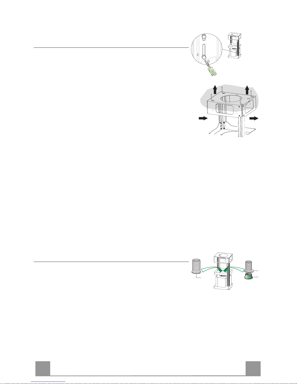
Fissaggio Traliccio
• Svitare le due viti che fissano il camino inferiore e sfilarlo dal
traliccio (dalla parte inferiore).
• Svitare le due viti che fissano il camino superiore e sfilarlo dal
traliccio (dalla parte superiore).
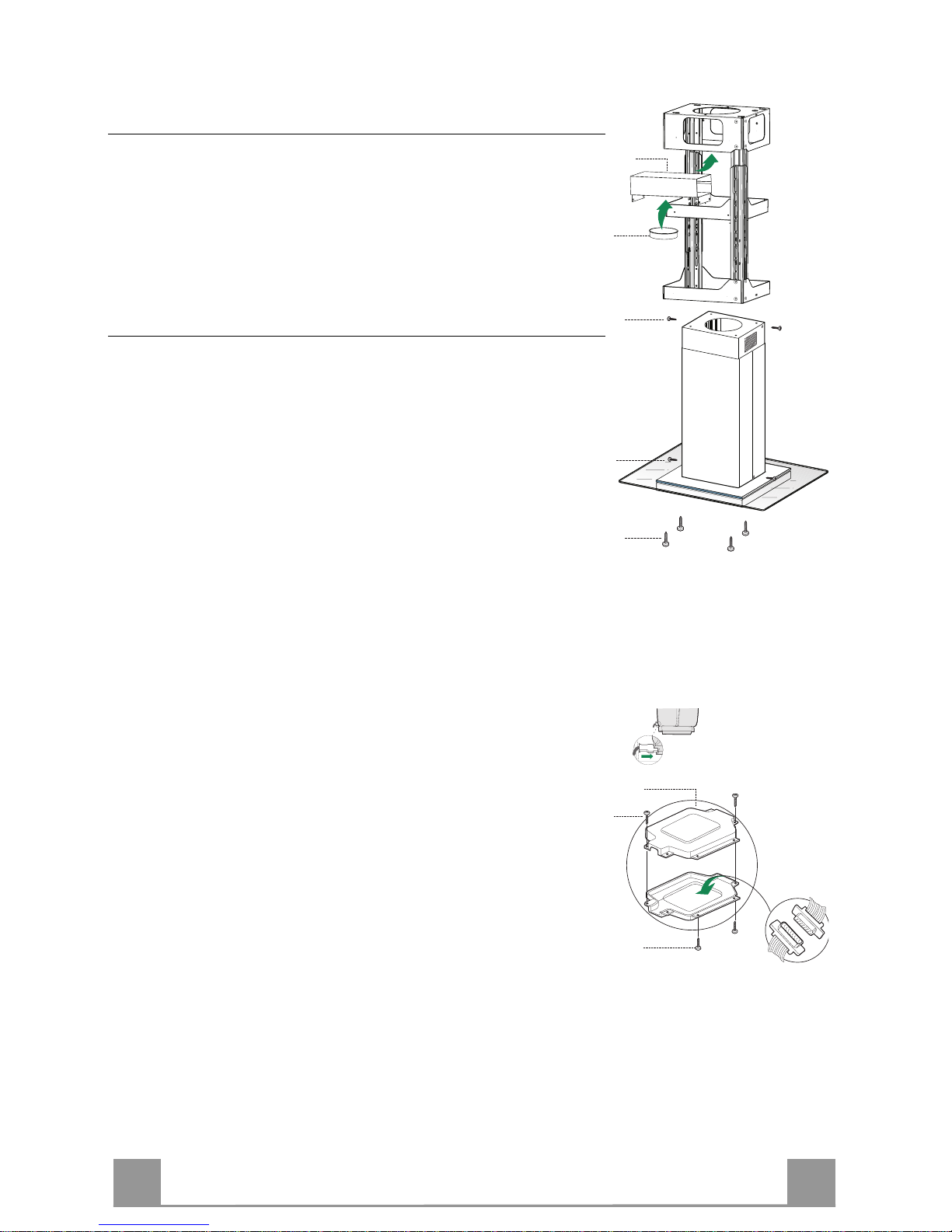
Nel caso in cui si voglia regolare l’altezza del traliccio procedere
come segue:
• Svitare le otto viti metriche che uniscono le due colonne, poste
ai lati del traliccio;
• Regolare l’altezza desiderata del traliccio e riavvitare le otto
viti precedentemente tolte;
• Inserire il camino superiore dall’ alto e lasciarlo libero sul traliccio;
• Sollevare il traliccio, incastrare le asole sulle viti e scorrere
fino a battuta;
• Stringere le due viti e avvitare le altre due in dotazione;
Prima di serrare definitivamente le viti è possibile effettuare delle
regolazioni spostando il traliccio, facendo attenzione che le viti
non escano dalla sede dell’asola di regolazione.
• Il fissaggio del Traliccio deve essere sicuro in relazione sia al
peso della Cappa sia alle sollecitazioni causate da occasionali
spinte laterali all’Apparecchio montato. A fissaggio avvenuto
verificare quindi che la base sia stabile anche se il Traliccio è
sollecitato a flessione.
• In tutti i casi in cui il Soffitto non fosse sufficientemente robusto sul punto di sospensione, l’Installatore dovrà provvedere a
irrobustirlo con opportune piastre e contropiastre ancorate a
parti strutturalmente resistenti.
2
2
1
1
Connessione Uscita aria Versione Aspirante
Per installazione in Versione Aspirante collegare la Cappa alla
tubazione di uscita per mezzo di un tubo rigido o flessibile di
ø 150 o 120 mm, la cui scelta è lasciata all’installatore.
• Per collegamento con tubo ø 120 mm, inserire la Flangia di
riduzione 9 sull’Uscita del Corpo Cappa.
• Fissare il tubo con adeguate fascette stringitubo 25 in dotazione.
• Rimuovere eventuali filtri al carbone attivo.
9
ø 150
ø 120
25
25
Page 12
IT 112
Uscita aria Versione Filtrante
• Fissare il Raccordo 15 al traliccio utilizzando le 4 Viti in dotazione.
• Incastrare la flangia 10 nell’apposito foro inferiore del Raccordo 15.
• Collegare l’uscita aria della cappa con la flangia posta sotto al
raccordo per mezzo di un tubo rigido o flessibile ø 150mm , la
cui scelta è lasciata all’installatore
15
10
Montaggio Camino e Fissaggio Corpo Cappa
• Posizionare il Camino superiore e fissare nella parte superiore
al Traliccio con 2 Viti 12c (2,9 x 6,5) in dotazione.
• Analogamente posizionare il Camino inferiore e fissare nella
parte inferiore al Traliccio con 2 Viti 12c (2,9 x 6,5) in dotazione.
Prima di fissare il Corpo Cappa al Traliccio:
• Togliere i Filtri antigrasso dal Corpo Cappa;
• Togliere eventuali Filtri Antiodore al Carbone attivo.
• Fissare quindi dal sotto, con 4Viti 12f (M6 x 10) in dotazione,
il Corpo Cappa al Traliccio predisposto.
12f
12c
12c
CONNESSIONE ELETTRICA
• Collegare la Cappa all’Alimentazione di Rete interponendo un
Interruttore bipolare con apertura dei contatti di almeno 3 mm.
• Rimuovere i Filtri antigrasso (vedi par. “Manutenzione”) e assicurarsi che il connettore del Cavo di alimentazione sia correttamente inserito nella presa dell’Aspiratore
• Collegare il Connettore dei Comandi Cmd.
• Riporre entrambi i Connettori nella Scatola di protezione 24
chiudendola con 2 Viti 12e(2,9 x 9,5) in dotazione.
• Fissare la Scatola di protezione al Corpo Cappa con 2 Viti 12c
(2,9 x 6,5) in dotazione.
• Per la Versione Filtrante montare il Filtro Antiodore al Carbone attivo.
• Rimontare i Filtri Antigrasso.
24
12e
Cmd
12c
Page 13
IT 113
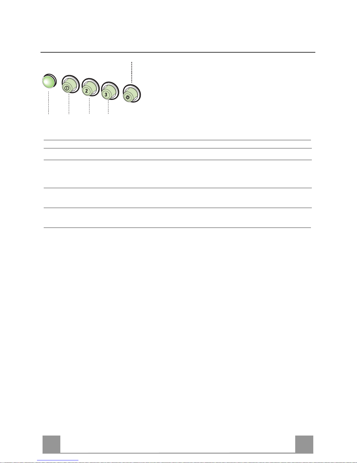
USO
L
V1 V2 V3
S
L Luci Accende e spegne l’Impianto di Illuminazione.
S Led Led accensione Motore.
V1 Motore Accende e spegne il motore Aspirazione a velocità minima, adatta ad un
ricambio d’aria continuo particolarmente silenzioso, in presenza di pochi
vapori di cottura.
V2 Velocità Velocità media, adatta alla maggior parte delle condizioni d’uso, dato
l’ottimo rapporto tra portata d’aria trattata e livello sonoro.
V3 Velocità Velocità massima, adatta a fronteggiare le massime emissioni di vapore di
cottura, anche per tempi prolungati.
Page 14
IT 114
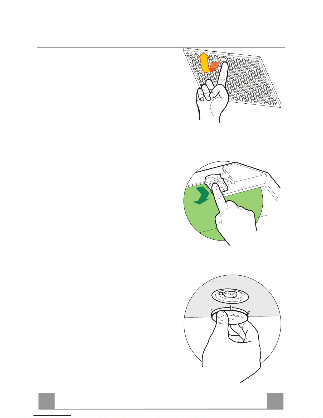
MANUTENZIONE
Filtri antigrasso
PULIZIA FILTRI AN TIGR A SSO ME TAL L ICI AUTO PO RTAN TI
• Sono lavabili anche in lavastoviglie, e necessitano di
essere lavati ogni 2 mesi circa di utilizzo o più frequentemente, per un uso particolarmente intenso.
• Togliere i Filtri uno alla volta,sostenendoli con una
mano mentre con l’altra si tira la leva verso il basso.
• Lavare i Filtri evitando di piegarli, e lasciarli asciugare prima di rimontarli.
• Rimontarli facendo attenzione a mantenere la mani-
glia verso la parte visibile esterna
Filtro antiodore (Versione Filtrante)
SOSTITUZIONE FILTRO ANTIODORE AL CARBONE ATTIVO
• Non è lavabile e non è rigenerabile, va sostituito
almeno ogni 4 mesi o più frequentemente, per un
uso particolarmente intenso.
• Togliere i Filtri antigrasso metallici.
• Rimuovere il Filtro antiodore al Carbone attivo
saturo, agendo sugli appositi agganci.
• Montare il nuovo Filtro agganciandolo nella sua
sede.
• Rimontare i Filtri antigrasso metallici.
Illuminazione
SOSTITUZIONE LAMPADE
Lampade alogene da 20 W
• Togliere il bloccavetro metallico a pressione facendo
leva sotto la ghiera, sostenendolo con una mano.
• Estrarre la lampadina alogena dal portalampada.
• Sostituirla con una nuova lampadina di uguali caratteristiche, facendo attenzione ad inserire correttamente i due spinotti nella sede del portalampade.
• Rimontare il bloccavetro a pressione.
Page 15
EN
115
RECOMMENDATIONS AND SUGGESTIONS
INSTALLATION
• The manufacturer will not be held liable for any damages resulting
from incorrect or improper installation.
• T he minimum safety di stance between the cooker top and the extrac tor hood is 650 mm.
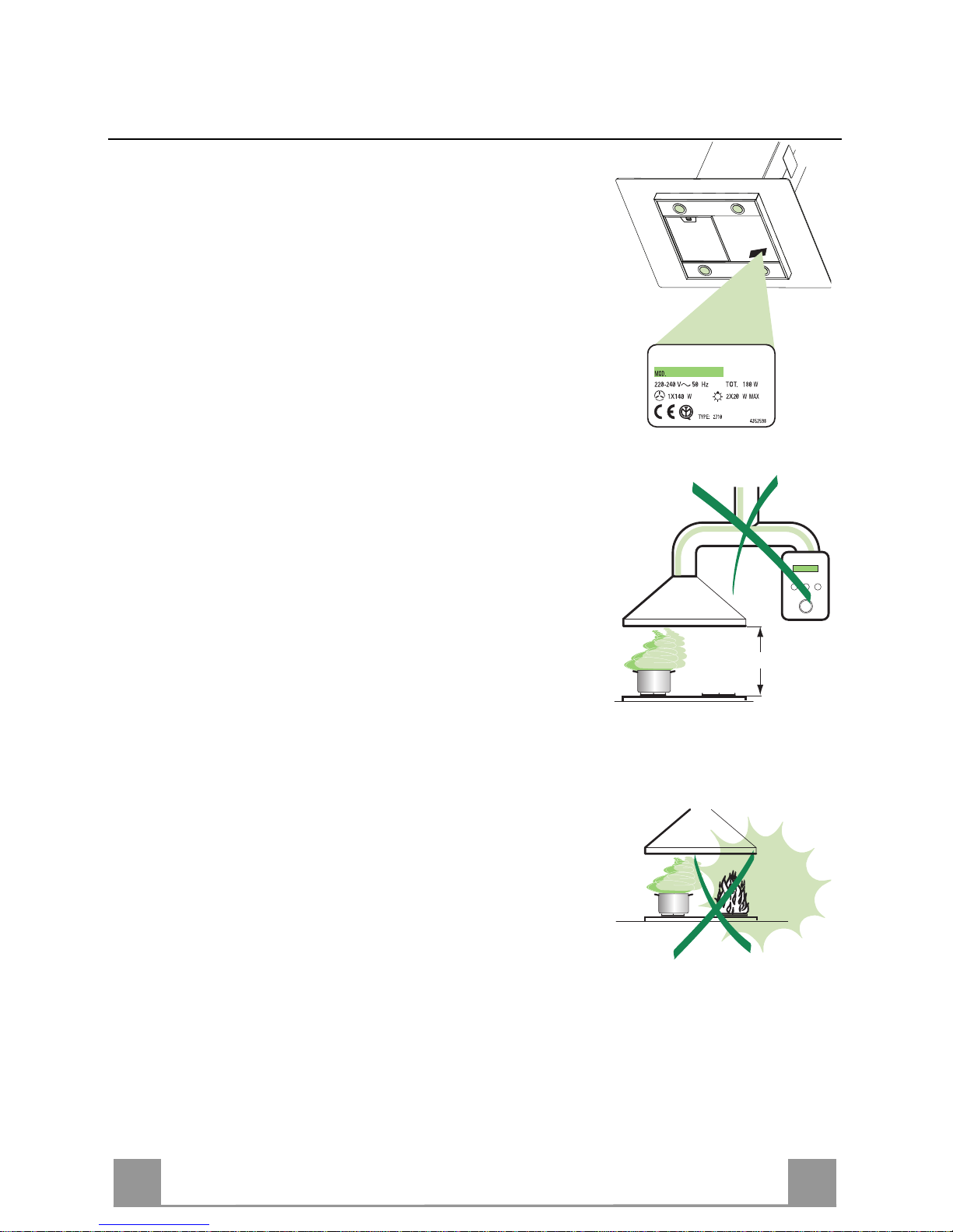
• Check that the mains voltage corresponds to that indicated on the
rating plate fixed to the inside of the hood.
• For Class I appliances, c hec k t hat th e domes ti c po wer suppl y gua ran tees adequate earthing.
Connect the extractor to the exhaust flue through a pipe of mi nimum
diameter 120 mm. The route of the flue must be as short as possible.
• Do not c onnect the extr actor hood to ex haust ducts carryi ng combustion fumes (boilers, fireplaces, etc.).
• If the extractor is used in conjunction with non-electrical appliances
(e.g. gas burning appliances), a suffi cient degree of aeration must be
guaranteed in the room in order to prevent the backflow of exhaust
gas. The kitchen must h ave an opening communicati ng directly with
the open air in order to guarantee the entry of clean air.
USE
• The extractor hood has been designed ex cl us iv ely for domesti c us e to
eliminate kitchen smells.
• Never use the hood for purposes other than for which i t has ben designed.
• Never leave high naked flames under the hood when it is in operation.
• Adjust the flame i ntensity to direct it onto the bottom of the pan only,
making sure that it does not engulf the sides.
• Deep fat fryers must be continuously monitored during use: overheated oil can burst into flames.
• The hood should not be used by c hildren or persons not instruc ted in
its correct use.
MAINTENANCE
• Switch off or unplug the appliance from the mains supply before carrying out any maintenance work.
• Clean and/or replace the Filters after the specified time period.
• Clean the hood using a damp cloth and a neutral liquid detergent.
650 mm min.
Page 16

EN
116
CHARACTERISTICS
Dimensions
Page 17

EN
117
Components
Ref. Q.ty Product Components
1 1 Hood Body, complete with: Controls, Light, Blower,
Filters
2 1 Telescopic Chimney comprising:
2.1 1 Upper Section
2.2 1 Lower Section
7.1 1 Telescopic frame complete with extractor, consisting of:
7.1a 1 Upper frame
7.1b 1 Lower frame
10 1 Flange ø 150
10a 1 Dumper ø 150mm
15 1 Air Outlet C onnection
24 1 Junction box
25 2 Pipe clamps
Ref. Q.ty Installation Components
11 4 Wall Plugs ø 10
12c 6 Screws 2,9 x 6,5
12e 2 Screws 2,9 x 9,5
12f 4 Screws M6 x 10
12g 4 Screws M6 x 80
12h 4 Screws 5,2 x 70
21 1 Drilling template
22 4 6.4 mm int. dia washers
23 4 M6 nuts
Q.ty Documentation
1 Instruction Manual
12c
7.1a
7.1
22
23
12h
7.1b
2
2.1
2.2
12c
11
21
12g
24
12e
15
12c
25
9
10
12f
1
9
10a
Page 18

EN
118
INSTALLATION
Drilling the Ceiling/shelf and fixing the frame
DRILLING TH E CEILING/SHELF
• Use a plumb line to mark the centre of the hob on the ceiling/support shelf.
• Place the drilling template 21 provided on the ceiling/support shelf, making sure that the
template is in the correct position by lining up the axes of the template with those of the hob.
• Mark the centres of the holes in the template.
• Drill the holes at the points marked:
• For concrete ceilings, drill for plugs appropriate to the screw size.
• For hollow brick ceilings with wall thickness of 20 mm: drill ø 10 mm(immediately insert
the Dowels 11 supplied).
• For wooden beam ceilings, drill according to the wood screws used.
• For wooden shelf, drill ø 7 mm.
• For the power supply cable feed, drill ø 10 mm.
• For the air outlet (Ducted Version), drill according to the diameter of the external air ex-
haust duct connection.
• Insert two screws of the following type, crossing them and leaving 4-5 mm from the ceiling:
• For concrete ceilings, use the appropriate plugs for the screw size (not provided).
• for Cavity ceiling with inner space, with wall thickness of approx. 20 mm, Screws 12h,
supplied.
• For wooden beam ceilings, use 4 wood screws (not provided).
• For wooden shelf, use 4 screws 12g with washers 22 and nuts 23, provided.
Page 19

EN
119
FIXING THE frame
• Loosen the two screws fastening the lower chimney and remove this from the lower frame.
• Loosen the two screws fastening the upper chimney and remove this from the upper frame.
If you wish to adjust the height of the frame, proceed as follows:
• Unfasten the eight metric screws joining the two columns, located at the sides of the frame.
• Adjust the frame to the height required, then replace all the
screws removed as above.
• Insert the upper chimney stack from above, and leave it running free on the frame.
• Lift up the frame, fit the frame slots onto the screws up to the
slot end positions.
• Tighten the two screws and fasten the other two screws provided with the hood.
Before tightening the screws completely it is possible to adjust
the frame by turning it. Make sure that the screws do not come
out of their seats in the slotted holes.
• The frame mountings must be secure to withstand the weight
of the hood and any stresses caused by the occasional side
thrust applied to the device.
On completion, check that the base is stable, even if the frame
is subjected to bending.
• In all cases where the ceiling is not strong enough at the suspension point, the installer must provide strengthening using
suitable plates and backing pieces anchored to the structurally
sound parts.
2
2
1
1
Ducted version air exhaust system Connection
When installing the ducted version, connect the hood to the
chimney using either a flexible or rigid pipe ø 150 or 120 mm,
the choice of which is left to the installer.
• To install a ø 120 mm air exhaust connection, insert the reducer flange 9 on the hood body outlet.
• Fix the pipe using the pipe clamps 25 provided.
• Remove any activated charcoal filters.
9
ø 150
ø 120
25
25
Page 20

EN
220
Recirculation version air outlet
• Fix the connection 15 to the frame using the 4 screws provided.
• Fix the flange 10 to the lower opening of the connection 15.
• Connect the hood air outlet to the flange in the lower part of
the junction using a rigid or flexible ø 150 tube (by installer’s
choice).
15
10
Flue assembly - Mounting the hood body
• Position the upper chimney section and fix the upper part to the
frame using the 2 screws 12c (2,9 x 6,5) provided.
• Similarly, position the lower chimney section and fix the
lower part to the frame using the 2 screws 12c (2,9 x 6,5) provided.
Before fixing the hood body to the frame:
• Remove the grease filters from the hood body.
• Remove any activated charcoal filters.
• From below, use the 4 screws 12f (M6 x 10)provided to fix the
hood body to the frame.
12f
12c
12c
ELECTRICAL CONNECTION
• Connect the hood to the mains through a two-pole switch having a contact gap of at least 3 mm.
• Remove the grease filters (see paragraph Maintenance) being
sure that the connector of the feeding cable is correctly inserted
in the socket placed on the side of the fan.
• Connect the control connector Cmd.
• Place the connectors in the junction box 24 and close it using
the 2 screws 12e (2,9 x 9,5) provided.
• Fix the junction box to the hood body using the 2 screws 12c
(2,9 x 6,5) provided.
• For the recirculation version, fit the activated carbon odour filter.
• Replace the grease filters.
24
12e
Cmd
12c
Page 21

EN
221
USE
L
V1 V2 V3
S
L Light Switches the lighting system on and off.
S Led Motor running led.
V1 Motor Switches the extractor motor on and off at low speed. Used to provide a
contin-uos and silent air change in the presence of light cooking vapours.
V2 Speed Medium speed, suitable for most operating conditions given the optimum
treated air flox/noise level ratio.
V3 Intensive Maximum speed, used for eliminating the highest cooking vapour emission,
including long periods.
Page 22

EN
222
MAINTENANCE
Grease filters
CLEANING METAL SELF- SUPPORTI NG GREASE FI LTERS
• The filters must be cleaned every 2 months of operation, or more frequently for particularly heavy usage,
and can be washed in a dishwasher.
• Remove the filters one at a time holding them up
with one hand and pulling the handle downwards
with the other hand at the same time.
• Wash the filters, taking care not to bend them. Allow
them to dry before refitting.
• When refitting the filters, make sure that the handle
is visible on the outside.
Activated charcoal filter (Recirculation version)
REPLACING THE ACTIVATED CHARC OAL FILTER
• The filter is not washable and cannot be regenerated, and must be replaced approximately every 4
months of operation, or more frequently for particularly heavy usage.
• Remove the metal grease filters
• Remove the saturated activated carbon filter by
releasing the fixing hooks
• Fit the new filter by hooking it into its seating
• Replace the metal grease filters.
Lighting
LIGHT REPLACEMENT
20 W halogen light.
• Remove the snap-on lamp cover by levering it from
under the metal ring, supporting it with one hand.
• Remove the halogen lamp from the lamp holder by
pulling gently.
• Replace the lamp with a new one of the same type,
making sure that you insert the two pins properly into
the housings on the lamp holder.
• Replace the snap-on lamp cover.
Page 23

FR
223
CONSEILS ET SUGGESTIONS
INSTALLATION
• Le fabricant décline toute responsabilité en cas de dommage dû à
une installation non correcte ou non conforme aux règles de l’art.
• La distance mi nimale de sécurité entre l e plan de cuisson et la hotte
doit être de 650 mm au moins.
• Vérifier que la tension du s ecteu r c or respond à l a val eur qui figu re s ur
la plaquette apposée à l’intérieur de la hotte.
• Pour les Appareils appartenant à la Ière Classe, veiller à ce que la
mise à la terre de l’installation électrique domestique ait été effectuée
conformément aux normes en vigueur.
• Connecter la hotte à la sortie d’air aspiré à l’aide d’une tuyauterie
d’un diamètre égal ou supérieur à 120 mm. Le parcours de la
tuyauterie doit être le plus court possible.
• Eviter de connecter la hotte à des conduites d’évacuation de fumées
issues d’une combustion tel que (Chaudière, cheminée, etc…).
• Si vous utilisez des appareils qui ne fonctionnent pas à l’électricité
dans la pièce ou est installée la hotte (par exemple: des appareils
fonctionnant au gaz), vous devez prévoir une aération suffisante du
milieu. Si la cuisine en est dépourvue, pratiquez une ouverture qui
communique avec l’extérieur pour garantir l’infiltration de l’air pur.
UTILISATION
• La hotte a été conç ue exclusivement pour l’us age domestique, dans
le but d’éliminer les odeurs de la cuisine.
• Ne jamais utiliser abusivement la hotte.
• Ne pas laisser l es flammes libres à forte intensité quand la hotte est
en service.
• Toujours régler les flammes de manière à éviter toute sortie latérale
de ces dernières par rapport au fond des marmites.
• Contrôler les friteuses lors de l’utilisation car l’huile surchauffée
pourrait s’enflammer.
• La hotte ne doit pas être utilisée par des enfants ou des per s onnes ne
pouvant pas assurer une utilisation correcte.
ENTRETIEN
• Avant de procéder à toute opération d’entretien, retirer la hotte en
retirant la fiche ou en actionnant l’interrupteur général.
• Effectuer un entretien scrupuleux et en temps dû des Filtres, à la
cadence conseillée.
• Pour le nettoyage des surfaces de la hotte, il suffit d’utiliser un
650 mm min.
Page 24

FR
224
CARACTERISTIQUES
Encombrement
Page 25

FR
225
Composants
Réf. Q.té Composants de Produit
1 1 Corps Hotte équipé de: Comandes, Lumière, Filtres
2 1 Cheminée Télescopique formée de :
2.1 1 Cheminée Supérieure
2.2 1 Cheminée Inférieure
7.1 1 Treillis télescopique avec Aspirateur, formé par:
7.1a 1 Treillis supérieur
7.1b 1 Treillis inférieur
10 1 Flasque ø 150
10a 1 Buse avec clapet ø 150
15 1 Raccord Sortie Air
24 1 Boîte connexions
25 2 Colliers de serrage serre-tube
Réf. Q.té Composants pour l’installation
11 4 Chevilles ø 10
12c 6 Vis 2,9 x 6,5
12e 2 Vis 2,9 x 9,5
12f 4 Vis M6 x 10
12g 4 Vis M6 x 80
12h 4 Vis 5,2 x 70
21 1 Gabarit de perçage
22 4 Rondelles øi 6,4
23 4 Écrous M6
Q.té Documentation
1 Manuel d’instructions
12c
7.1a
7.1
22
23
12h
7.1b
2
2.1
2.2
12c
11
21
12g
24
12e
15
12c
25
9
10
12f
1
9
10a
Page 26

FR
226
INSTALLATION
Perçage Plafond/Étagère et Fixation Treillis
PERÇAGE PLAFOND/ETAGERE
• À l’aide d’un Fil à plomb, reporter sur le Plafond/Étagère de support le centre du Plan de
Cuisson.
• Poser contre le Plafond/Étagère le Gabarit de Perçage 21 fourni avec l’appareil, en faisant
coïncider son centre avec le centre projeté et en alignant les axes du Gabarit avec les axes du
Plan de Cuisson.
• Marquer les centres des Trous du Gabarit.
• Percer les trous qui ont été marqués:
• Plafond en Béton massif: en fonction des Goujons pour Béton utilisés.
• Plafond en Briques avec chambre à air, avec épaisseur résistante de 20 mm: ø 10 mm (in-
sérer immédiatement les Chevilles 11 fournies avec l’appareil).
• Plafond en Poutrage en Bois: en fonction des Vis à Bois utilisées.
• Étagère en Bois: ø 7 mm.
• Passage du Câble électrique d’Alimentation: ø 10 mm.
• Sortie Air (Version Aspirante): en fonction du diamètre de la connexion avec les Tuyaux
d’Évacuation Externe.
• Visser deux vis en les croisant et en laissant 4-5 mm. de distance par rapport au plafond:
• pour le Béton massif, des Goujons pour Béton, non fournis avec l’appareil.
• pour Briques percées, ayant une épaisseur résistante de 20 mm. environ, utiliser les Vis
12h, fournies avec l'appareil.
• pour le Poutrage en bois, 4 Vis à bois, non fournies avec l’appareil.
• pour l’Étagère en Bois, 4 Vis 12g avec Rondelles 22 et Écrous 23, fournis avec l’appareil.
Page 27

FR
227
FiXATION TREILLIS
• Dévisser les deux vis qui fixent la cheminée inférieure et sortir
cette dernière du treillis (depuis la partie inférieure).
• Dévisser les deux vis qui fixent la cheminée supérieure et sortir
cette dernière du treillis (depuis la partie supérieure).
Si l’on souhaite régler la hauteur du treillis, effectuer les opérations suivantes:
• Dévisser les huit vis métriques qui unissent les deux colonnes,
qui se trouvent sur les côtés du treillis.
• Régler la hauteur souhaitée du treillis et revisser les vis qui ont
été précédemment retirées.
• Insérer la cheminée supérieure depuis le haut et la laisser libre
sur le treillis.
• Soulever le treillis, encastrer les oeillets sur les vis et faire coulisser jusqu’à la butée;
• Serrer les deux vis et visser les autres deux vis fournies avec
l’appareil;
Avant de serrer définitivement les vis, il est possible d’effectuer
des réglages, en déplaçant le treillis, tout en contrôlant que les vis
ne sortent pas du logement de l’œillet de réglage.
• La fixation du Treillis doit être solide, en fonction du poids de
la Hotte et des contraintes provoquées par les poussées latérales occasionnelles auxquelles l’Appareil monté sera soumis.
Après avoir effectué la fixation, vérifier que la base soit stable,
même si le Treillis est soumis à des contraintes de flexion.
• Dans tous les cas où le Plafond ne devait pas être suffisamment
robuste en correspondance du point d’accrochage, l’Installateur
devra se charger de le rendre plus solide au moyen de plaques
et contre-plaques spéciales, ancrées sur les parties structuralement résistantes.
2
2
1
1
SORTIE AIR VERSION ASPIRA NTE
En cas d’installation en version aspirante, brancher la hotte à la
tuyauterie de sortie via un tube rigide ou flexible de ø 150 ou 120
mm, au choix de l’installateur.
• En cas de branchement avec un tube de ø120 mm, insérer le
flasque de réduction 9 sur la sortie du corps de la hotte.
• Fixer le tuyau à l’aide des Colliers de serrage serre-tube 25
fournis avec l’appareil.
• Retirer les éventuels filtres anti-odeur au charbon actif.
9
ø 150
ø 120
25
25
Page 28

FR
228
Sortie air version Filtrante
• Fixer le raccord 15 au Treillis à l’aide des 4 Vis fournies avec
l’appareil.
• Bloquer la bride 10 dans le trou inférieur de le raccord 15.
• Joindre la sortie d’air de la hotte avec la bride placée sous la
rallonge par un tuyau rigide ou flexible ø 150 ( le choix est de
l’installateur).
15
10
Montage Cheminée - Montage Corps Hotte
• Positionner la Cheminée supérieure et fixer cette dernière dans
la partie supérieure du Treillis à l’aide de 2 Vis 12c (2,9 x 6,5)
fournies avec l’appareil.
• De la même façon, positionner la Cheminée inférieure et fixer
cette dernière dans la partie inférieure du Treillis à l’aide de 2
Vis 12c (2,9 x 6,5) fournies avec l’appareil.
Avant de fixer le Corps de la Hotte au Treillis:
• Retirer les Filtres anti-graisse du Corps de la Hotte.
• Retirer les éventuels Filtres Anti-odeur au Charbon actif.
• Ensuite, fixer par le bas, au moyen de 4 Vis 12f (M6 x 10)
fournies avec l’appareil, le Corps de la Hotte au Treillis prévu.
12f
12c
12c
BRANCHEMENT ELECTRIQUE
• Brancher la hotte sur le secteur en interposant un interrupteur
bipolaire avec ouverture des contacts d’au moins 3 mm.
• Enlever les filtres à graisse (voir "Entretien") et s'assurer que le
connecteur du câble d'alimentation soit bien branché dans la
prise du diffuseur.
• Connecter le Connecteur des Commandes Cmd.
• Ranger les Connecteurs dans la Boîte de protection 24 en la
fermant à l’aide des 2 Vis 12e (2,9 x 9,5) fournies avec
l’appareil.
• Fixer la Boîte de protection au Corps de la Hotte à l’aide des 2
Vis 12c (2,9 x 6,5) fournies avec l’appareil.
• Pour la Version Filtrante, monter le Filtre Anti-odeur au Charbon actif.
• Remonter les Filtres Anti-graisse.
24
12e
Cmd
12c
Page 29

FR
229
UTILISATION
L
V1 V2 V3
S
L Lumières Allume et éteint l’installation de l’éclairage.
S Del Del allumage Moteur.
V1 Moteur Met en marche et à l’arrêt le moteur aspiration à vitesse minimale, pour un
rechange d’air permantent particulièrement silencieux en cas de faibles vapeurs de cuisson.
V2 Vitesse Vitesse moyenne pour la plupart des conditions d’utilisation, étant donné le
rapport optimal entre débit d’air traité et niveau sonore.
V3 Vitesse Vitesse maximum, pour faire face aux émissions maximum de vapeur de
cuisson, même pendant des temps prolongés.
Page 30

FR
330
ENTRETIEN
Filtres anti-graisse
NETTOYAGE FILTRES ANTI-GRAISSE METALLIQUES AUTOPORTEURS
• Lavables au lave-vaisselle, ils doivent être lavés environ tous les 2 mois d’emploi ou plus fréquemment
en cas d’emploi particulièrement intense.
• Enlevez les filtres l’un après l’autre en les soutenant
avec une main et en tirant en même temps la poignée
vers le bas avec l’autre main.
• Laver les filtres en évitant de les plier et les laisser
sécher avant de les remonter.
• Remonter les filtres en veillant à ce que la poignée
reste vers la partie visible externe
Filtre anti-odeur (Version filtrante)
REMPLACEMENT FILTRE AU CHARBON ACTIF
• Ni lavable, ni régénérable, le remplacer au moins
tous les 4 mois d’emploi ou plus fréquemment en
cas d’emploi particulièrement intense.
• Retirer les filtres anti-graisse métalliques.
• Retirer le filtre anti-odeur au charbon actif colmaté, en agissant sur les crochets prévus à cet effet.
• Monter le nouveau filtre anti-odeur au charbon
actif.
• Remonter les filtres anti-graisse métalliques.
Eclairage
REMPLACEMENT LAMPES
Lampe halogène de 20 W.
• Enlever le dispositif métallique de blocage du verre
par encliquetage en exerçant une pression sous
l’embout en le soutenant d’une main.
• Extraire la lampe du support
• Remplacer la lampe par une nouvelle ayant le mêmes
caractéristiques, en prenant soin d'insérer correctement les deux fiches dans le support.
• Remonter le dispositif de blocage du verre par encli-
quetage.
Page 31

DE
331
EMPFEHLUNGEN UND HINWEISE
MONTAGE
• Der Hersteller haftet nicht für Schäden, die auf eine fehle rhafte und
unsachgemäße Montage zurückzuführen sind.
• Der minimale Sicherheitsabstand zwischen Kochmulde und Haube
muss 650 mm betragen.
• Prüfen, ob di e Netzspannung mi t dem Wert auf dem im Haubeninn eren angebrachten Schild übereinstimmt.
• Bei Geräten der Kl asse I ist sicherzustell en, dass die elektrische Anlage des Wohnhauses über eine vorschriftsmäßige Erdung verfügt.
• Das Anschlussrohr der Haube zur Luftaustrittsöffnung muss einen
Durchmesser von 120 mm oder darüber aufweisen. Der Roh rverlauf
muss so kurz wie möglich sein.
• Die Haube darf an keine Entlüftungssc hächte angeschl ossen werde n,
in die Verbrennungsgase (Heizkessel, Kamine usw.) geleitet werden.
• Werden im Raum außer der Dunstabzugshaube and ere, nicht elektrisch betriebene (z.B. gasbe triebene) Geräte verwend et, muss für eine ausreichende Belüftung ges orgt werden. Sollte die Küche di esbezüglich nicht entsprechen, i st an einer Aussenwa nd eine Öffnung anzubringen, die Frischluftzufuhr gewährleistet.
BEDIENUNG
• Die Dunstabzugshaube ist ausschließlich zum Einsatz im privaten
Haushalt und zur Beseitigung von Küchengerüchen vorgesehen.
• Unsachgemäßer Einsatz der Haube ist zu unterlassen.
• Große Flammen bei eingeschalteter Haube niemals unbedeckt lassen.
• Die Intensivität der Flamme ist s o zu reguliere n, dass si e den Topfboden nicht überragt.
• Frittiergeräte müssen während des Gebrauchs stets beaufsichtigt
werden: überhitztes Öl kann sich entzünden.
• Die Dunstabzugshaube darf v on Ki ndern oder Pe rsonen, di e hinsi chtlich der Bedienung nicht unterwiesen wurden, keinesfalls verwendet
werden.
WARTUNG
• Bevor Wartun gsarbeiten durchgef ührt werden, muss di e Stromzufuhr
zur Haube unterbrochen werden, indem der Stecker gezogen oder
der Hauptschalter abgeschaltet wird.
• Bei der Filterwartung müssen die vom Hersteller empfohlenen Zeiträume zum Austauschen der Filter genauestens eingehalten werden.
• Zur Reinigung der Haubenflächen Wir empfehlen ein feuchtes Tuch
und ein mildes Flüssigreinigungsmittel.
650 mm min.
Page 32

DE
332
CHARAKTERISTIKEN
Platzbedarf
Page 33

DE
333
Komponenten
Pos. St. Produktkomponenten
1 1 Haubenkörper mit Schaltern,
2 1 Teleskopkamin bestehend aus:
2.1 1 oberer Kaminteil
2.2 1 unterer Kaminteil
7.1 1 Teleskopgerüst komplett mit Ge bläse, bes tehend aus:
7.1a 1 oberer Gerüstteil
7.1b 1 unterer Gerüstteil
10 1 Flansch ø 150
10a 1 Flansch mit Ruckstauklappe ø 150
15 1 Luftaustritt-Anschlussstück
24 1 Verbindungsdose
25 2 Rohrschellen
Pos. St. Montagekomponenten
11 4 Bügel ø 10
12c 6 Schrauben 2,9 x 6,5
12e 2 Schrauben 2,9 x 9,5
12f 4 Schrauben M6 x 10
12g 4 Schrauben M6 x 80
12h 4 Schrauben 5,2 x 70
21 1 Bohrschablone
22 4 Unterlegscheiben ø 6,4
23 4 Schraubenmuttern M6
St. Dokumentation
1 Bedienungsanleitung
12c
7.1a
7.1
22
23
12h
7.1b
2
2.1
2.2
12c
11
21
12g
24
12e
15
12c
25
9
10
12f
1
9
10a
Page 34

DE
334
MONTAGE
Bohren der Decke/Trägerplatte und Montage des Teleskopgerüsts
BOHREN DER DECKE/TRAGERPLATTE
• Mit Hilfe eines Lots den Kochmulden-Mittelpunkt an der Decke oder Trägerplatte ermitteln
und kennzeichnen.
• Die mitgelieferte Bohrschablone 21 so auf die Decke/Trägerplatte legen, dass die Schablo-
nenmitte mit dem gekennzeichneten Mittelpunkt übereinstimmt und die Schablonenseiten
auf die Seiten der Kochmulde ausrichten.
• Die Mitte der Schablonenbohrungen kennzeichnen.
• Die gekennzeichneten Punkte bohren:
• Massivbeton-Decke: je nach verwendeten Beton-Dübeln.
• Decke aus Hohlkammer-Ziegeln mit 20 mm Wandungsstärke: ø 10 mm (sofort die mitge-
lieferten Dübel 11 einfügen).
• Holzbalkendecke: je nach verwendeten Holzschrauben.
• Holz-Trägerplatte: ø 7 mm.
• Durchgang für das Speisekabel: ø 10 mm.
• Luftaustritt (Abluftversion): je nach Durchmesser des Anschlussrohres für die Luftablei-
tung.
• Zwei sich gegenüberliegende Schrauben festziehen und 4-5 mm Freiraum zur Decke belassen:
• bei Massiv-Betondecken mit speziellen Betondübeln, die nicht mitgeliefert werden;
• für Hohlkammer-Ziegeln mit ca. 20 mm Wandungsstärke die mitgelieferten Schrauben
12h verwenden;
• bei Holzbalken-Decken mit 4 Holzschrauben, die nicht mitgeliefert werden;
• bei Holz-Trägerplatten mit 4 Schrauben 12g, Unterlegscheiben 22 und Schraubenmuttern
23, die im Lieferumfang enthalten sind.
Page 35

DE
335
MONTAGE DES TELESKO PG E RÜST S
• Die beiden Schrauben lösen, die den unteren Kaminteil fixieren und diesen aus dem Gerüst ziehen (an der Unterseite)
• Die beiden Schrauben lösen, die den oberen Kaminteil fixieren
und diesen aus dem Gerüst ziehen (an der Oberseite).
Für eine eventuelle Regulierung der Gerüsthöhe folgendermaßen
vorgehen:
• Die acht Stellschrauben an den Gerüstseiten, die die beiden
Säulen vereinen, lösen.
• Den oberen Kaminteil von oben einfügen und frei auf dem Gerüst lassen.
• Das Gerüst heben, die Langlöcher bei den Schrauben einrasten
und bis zum Anschlag laufen lassen;
• Die beiden Schrauben festziehen und die beiden anderen mitgelieferten Schrauben einschrauben;
Bevor die Schrauben definitiv festgezogen werden, kann eine
Regelung durch Bewegen des Gerüstes erfolgen, wobei darauf zu
achten ist, dass die Schrauben nicht aus dem Sitz des Regellangloches austreten.
• Wir verweisen auf die Notwendigkeit einer absolut sicheren
Befestigung des Teleskopgerüsts, die sowohl dem Eigengewicht der Haube wie auch dem seitlichen Druck, der auf das
Gerät einwirken kann, entsprechen muss. Nach erfolgter Montage ist zu prüfen, ob das Teleskopgerüst auch bei Biegebeanspruchung stabil ist.
• Sollte die Decke am Befestigungspunkt nicht robust genug
sein, muss der Installateur geeignete Platten und Gegenplatten
verwenden, die an strukturell widerstandsfähigen Teilen verankert werden.
2
2
1
1
Anschluss in Abluftversion
Bei Abluftbetrieb kann die Haube vom Installateur wahlweise
mittels Rohr oder Schlauch (ø 150 oder 120 mm) an die Außenrohrleitung angeschlossen werden.
• Bei Verwendung eines Anschlussrohres ø 120 den Reduzierflansch 9 am Haubenaustritt anbringen.
• Das Rohr mit den mitgelieferten Rohrschellen 25 fixieren.
• Eventuell vorhandene Aktivkohlefilter entnehmen.
9
ø 150
ø 120
25
25
Page 36

DE
336
Anschluss in Umluftversion
• Der Anschluß 15 an das Teleskopgerüst mit den 4 beiliegenden
Schrauben befestigen.
• Den Flansch 10 an die untere Bohrung des Anschluß 15 an-
bringen.
• Den Haubenluftaustritt mit Hilfe eines Rohres oder Schlauches
Ø 150 (die Wahl bleibt dem Installateur überlassen) mit dem
Flansch, der sich unter dem Umlenkteil befindet, verbinden.
15
10
Kaminmontage und Montage des Haubenkörpers
• Den oberen Kaminteil positionieren und beim oberen Gerüstteil mit Hilfe der 2 mitgelieferten Schrauben 12c (2,9 x 6,5) fixieren.
• Gleichermaßen den unteren Kaminteil positionieren und beim
unteren Gerüstteil mit Hilfe der 2 mitgelieferten Schrauben 12c
(2,9 x 6,5) fixieren.
Vor der Montage des Haubenkörpers am Teleskopgerüst:
• Die Fettfilter entnehmen.
• Eventuell vorhandene Aktivkohle-Geruchsfilter entnehmen.
• Dann den Haubenkörper mit Hilfe der 4 mitgelieferten Schrauben 12f (M6 x 10) von unten her am Teleskopgerüst fixieren.
12f
12c
12c
ELEKTROANSCHLUSS
• Bei Anschluss der Haube an das Stromnetz muss ein zweipoliger Schalter mit einem Öffnungsweg von mindestens 3 mm
zwischengeschaltet werden.
• Entfernen Sie die Fettfilter (s. Abschnitt „Wartung“) und versichern Sie sich, daß die Kabelverbindung in die Steckdose des
Gebläses einwandfrei eingesteckt wird.
• Den Verbinder der Steuerungen Cmd anschlie- ßen.
• Den Verbinder wieder in die Verbindungsdose 24 stecken und
diese mit den 2 mitgelieferten Schrau-ben 12e (2,9 x 9,5) verschließen.
• Die Verbindungsdose mit den 2 beiliegenden Schrauben 12c
(2,9 x 6,5) am Haubenkörper fixieren.
• Bei Umluftbetrieb den Aktivkohle-Geruchsfilter montieren.
• Die Fettfilter wieder montieren.
24
12e
Cmd
12c
Page 37

DE
337
BEDIENUNG
L
V1 V2 V3
S
L Beleucht. Schaltet die Beleuchtung ein und aus.
S Led Betriebsanzeigelampe.
V1 Motor Schaltet den Gebläsemotor mit minimaler Geschwindigkeit ein oder aus.
Diese Stufe ist für einen ständigen und besonders leisen Luftaustausch bei
geringer Kochdunstentwicklung geeignet.
V2 Geschw. Mittlere Gebläsestufe, eignet sich aufgrund des guten Verhältnisses zwi-
schen Fördervolumen und Geräuschentwicklung für die meisten Anwendungssituationen.
V3 Geschw. Höchste Gebläsestufe, eignet sich für starke Kochdunstentwicklung, auch
über längere Zeit hin.
Page 38

DE
338
WARTUNG
Fettfilter
SELBSTTRAGENDER METALLFETTFILTER R EINIGUNG
• Sie müssen nach 2-monatigem Betrieb bzw. bei starkem Einsatz auch häufiger gereinigt werden, was im
Geschirrspüler möglich ist.
• Einen Filter nach dem anderen entfernen. Halten Sie
den Filter mit einer Hand fest und ziehen Sie den
Griff mit der anderen Hand gleichzeitig nach unten.
• Die Filter reinigen (darauf achten, sie nicht zu verbiegen) und vor der Remontage trocknen lassen.
• Bei der Remontage ist darauf zu achten, dass sich der
Griff auf der sichtbaren Außenseite befindet.
Geruchsfilter (Umluftversion)
AUSTAUSCHEN DER AKTIVKOHLE FI LTER
• Dieser Filter kann weder gewaschen noch wiederverwendet werden und ist alle 4 Betriebsmonate
bzw. bei starkem Einsatz auch häufiger auszutauschen.
• Die Metallfettfilter entfernen.
• Den gesättigten Aktivkohle-Geruchsfilter aushaken.
• Den neuen Filter in seinem Sitz einhaken.
• Die Metallfettfilter wieder montieren.
Beleuchtung
AUSWECHSELN DER LAMPEN
Halogenlampe 20 W
• Die mittels Eindrücken befestigte Glashalterung aus
Metall durch Anheben der Zwinge entfernen und die
Halterung dabei mit einer Hand stützen.
• Die Lampe aus der Halterung nehmen.
• Die Lampe durch eine gleichwertige ersetzen und bei
der Remontage darauf achten, daß die beiden Steckerstifte vorschriftsmäßig in die Lampenfassung
eingeführt werden.
• Die Glashalterung wieder eindrücken.
Page 39

TR
339
TAVSIYELER VE ÖNERILER
MONTAJ
• Yalnιş veya eksik montajdan doğan herhangi bir zararιn
sorumluluğu üreticiye ait değildir.
• Davlumbaz ile pişirici cihazιn ocak kιsmι arasιndaki minimum
güvenlik mesafesi 650 mm.dir.
• Besleme voltajιnιn, davlumbaz içerisine yerleştirilen bilgi
etiketinde belirtilenle aynι olup olmadιğιnι kontrol edin.
• Sιnιf I elektrikli aletleri için, güç kaynağιnιn yeterli topraklamayι
sağlayιp sağlamadιğιnι kontrol edin. Minimum 120 mm çapιnda
bir boru yoluyla davlumbazι çιkιş bacasιna bağlayιn. Baca
bağlantιsι mümkün oldu- ğunca kιsa olmal ιdιr.
• Davlumbaz borus unu yanιcι duman taşιyan baca deliğine (buhar
kazanι, şömine, vb .) bağlamayιn.
• Davlumbazιn elektrikle çalιşmayan aletlerle (örneğin; gazlι
cihazlar) bağιntιlι olarak kullanιlmamasι halinde çιkιş gazιnιn geri
tepmesini önlemek amacιyla odada yeterli bir havalandιrma
sağlanmalιdιr.Temiz hava girişini temin etmek için mutfakta
doğrudan dιşarιya açιlan b ir açιklιk bulunmalιdιr.
KULLANIM
• Davlumbaz mutfaktaki kokularιn emilmesi amacιyla evlerde
kullanιm için tasarlanmιştιr.Ticari ve endüstriyel amaçlar için
kullanmayιnιz.
• Davlumbazι tasarlandιğι amaçlarιn dιşιnda kesinlikle
kullanmayιnιz.
• Davlumbaz çalιşιrken altιnda kesinlikle yüksek çιplak ateş
bιrakmayιn.
• Alev yoğunluğunu doğrudan tencerenin altιnda kalacak şekilde
ayarlayιn, kenarlarιnι sarmadιğιndan emin olun.
• Yağda kιzartma tavalarιnι kullanιrken sürekli olarak takip edin:
fazla ιsιnan yağ tutuşabilir.
• Davlumbaz çocuklar veya doğru kullanιm konusunda bilgisi
olmayan kişiler tarafιndan kullanιlmamalιdιr.
BAKIM
• Herhangi bir bakιm işlemini gerçekleştirmeden önce davlumbazι
kapatιn veya fişini çιkarιn.
• Fil treleri belirtilen zamanlarda temizleyin ve / veya değiştirin.
• Cihazι nemli bir bez ve nötr bir sιvι deterjan kullanarak
temizleyin.
650 mm min.
Page 40

TR
440
ÖZELLIKLER
Boyutlar
Page 41

TR
441
Parçalar
Ref. Adet Ürün Parçaları
1 1 Şunlardan oluşan Davlumbaz Gövdesi: Kumandalar,
Lamba, Filtreler
2 1 Şunlardan oluşan Teleskopik Bac a:
2.1 1 Üst Baca
2.2 1 Alt Baca
7.1 1 Şunlardan oluşan Aspiratörlü teleskopik kafes :
7.1a 1 Üst kafes
7.1b 1 Alt kafes
10 1 Flanş ø 150
10a 1 Valfli flanş ø 150 mm
15 1 Hava Çıkışı Rakoru
24 1 Bağlantı kutusu
25 2 Boru kelepçeleri
Ref. Adet Montaj Parçaları
11 4 Dübeller ø 10
12c 6 Vidalar 2,9 x 6,5
12e 2 Vidalar 2,9 x 9,5
12f 4 Vidalar M6 x 10
12g 4 Vidalar M6 x 80
12h 4 Vidalar 5,2 x 70
21 1 Delik açma şablonu
22 4 Rondelal ar øi 6,4
23 4 Somunlar M6
Adet Belge
1 Talimat El Kitapçığı
12c
7.1a
7.1
22
23
12h
7.1b
2
2.1
2.2
12c
11
21
12g
24
12e
15
12c
25
9
10
12f
1
9
10a
Page 42

TR
442
MONTAJ
Tavan / Konsol delme işlemi ve Kafesin Sabitlenmesi
TAVANIN YADA KONSOLUN DELİNMESİ
• Bir şakül yardımıyla tavana ya da destek konsolüne pişirme tezgahının merkezini
işaretleyiniz.
• Tavana veya konsola donanımla birlikte verilen delik delme şablonunu (21) dayayınız ve
bunun merkeziyle işaretlenen merkezi birbirine çakıştırınız. Yani şablonun ekseni ile
pişirme tezgahı ekseni bir hizaya gelmiş olsun.
• Delik delme şablonuyla delikleri duvara işaretleyiniz.
• Şu şekilde delik deliniz:
• Masif beton tavan: beton dübelleri kullanarak.
• Direnç kalınlığı 20 mm ve üstte hava boşluğu olan tuğla tavan: 10 mm çapında delik
(donanımla verilmiş dübelleri (11) hemen takınız)
• Ahşap tavan: ahşap dübelleri kullanarak.
• Ahşap konsola: 7 mm çapında delik deliniz.
• Elektrik besleme kablosunun geçişi için: ø 10 mm çapında.
• Hava Çıkışı (Aspiratörlü model): Dış hava tahliye borusu bağlantısının çapına göre.
• Tavana çaprazlamasına iki vida takıp 4-5 mm dışarıda bırakınız. Bu vidalar şöyle olmalıdır:
• Masif beton için buna uygun vida ve dübeller; bunlar donanımla verilmemiştir.
• Hava boşluklu tuğla tavan - yaklaşık 20 mm direnç kalınlıklı - bunun için donanımla
verilmiş vidaları (12h) kullanınız.
• Ahşap tavana uygun vidalar: donanımda yoktur.
• Ahşap konsola: donanımdaki vidalar (12g), rondelalar (22) ve cıvatalar (23).
Page 43

TR
443
Kafesin Sabitlenmesi
• Alt bacayı sabitleyen iki adet vidayı söküp kafesten çıkarınız
(alt kısımdan).
• Üst bacayı sabitleyen iki adet vidayı söküp kafesten çıkarınız
(üst kısımdan).
Kafesin yüksekliği ayarlanmak istenirse, şu şekilde hareket
edilmelidir:
• Kafesin iki yanında bulunan sütunları birleştiren sekiz adet
metrik vidayı sökünüz;
• Kafesin yüksekliğini istediğiniz seviyede ayarlayıp daha önce
sökmüş olduğunuz sekiz adet vidayı tekrar takarak sıkınız;
• Yukarı kısımdan üst bacayı geçiriniz ve kafes üzerinde serbest
bırakınız;
• Kafesi yukarı kaldırınız, delikleri vidalara geçirip dayanana
kadar kaydırınız;
• İki adet vidayı sıkıp bilahare cihaz donanımıyla verilmiş olan
iki adet diğer vidayı da takınız;
Vidaları nihai olarak sıkmadan önce, kafesi ayar delikleri
vidalardan çıkmadan kaydırmaya özen göstererek ayarlamak
mümkündür.
• Kafesin sabitlenmesi hem Davlumbazın ağırlığını
kaldırabilecek, hem de cihazın montajından sonra yandan
gelebilecek sarsmalara dayanacak şekilde mümkün olduğunca
sağlam yapılmalıdır. Sabitleme işlemi bittikten sonra, Kafesi
sarsınca ve esnetince bile kaidenin sabit ve sağlam şekilde
durduğunu kontrol ediniz.
• Askı noktasında tavanın yeterince sağlam olmadığı hallerde,
montör buraya uygun sıkı bağlantılı levha ve plakalar
uygulamak suretiyle tavan sağlamlığını arttırma yoluna
gitmelidir.
2
2
1
1
Aspiratörlü Model Hava Çıkışı Bağlantısı
Aspiratörlü modelin bağlantısını yapmak için, davlumbazı ø 150
yada 120 mm çapında, montörün seçimine göre sert veya esnek
bir boruyla çıkış kanalına bağlayınız.
• ø 120 mm çapında boruyla bağlantı için, redüksiyon flanşını
(9) davlumbaz gövdesi çıkışına takınız.
• Boruyu donanımla birlikte verilmiş kelepçelerle (25) sıkıca
raptediniz.
• Varsa aktif karbon filtrelerini çıkartınız.
9
ø 150
ø 120
25
25
Page 44

TR
444
Filtreli Model Hava Çıkışı
• Rakoru cihaz donanımındaki 4 adet Vida ile kafese
sabitleyiniz.
• Flanşı 10 Rakorun 15 bu işe ayrılmış alt deliğine geçiriniz.
• Davlumbazın flanşlı hava çıkışını, tercihi monitöre kalmış sert
ya da rijit 150 mm çapında bir boru ile rakora bağlayınız.
15
10
Baca Montajı ve Davlumbaz Gövdesinin Sabitlenmesi
• Üst Bacayı yerleştiriniz ve cihaz donanımındaki 2 adet vidayı
12c (2,9 x 6,5) kullanarak yukarı kısımdan Kafese sabitleyiniz.
• Aynı şekilde alt Bacayı da yerleştiriniz ve cihaz donanımındaki
2 adet vidayı 12c (2,9 x 6,5) kullanarak aşağı kısımdan Kafese
sabitleyiniz.
Davlumbaz Gövdesini Kafese sabitlemeden önce:
• Davlumbaz Gövdesinden yağ tutucu Filtreleri çıkarınız.;
• Varsa, Aktif Karbonlu Koku Filtrelerini de çıkarınız.
• Şimdi de alt taraftan cihaz donanımındaki 4 adet 12f (M6 x 10)
vidayı kullanarak Davlumbaz Gövdesini önceden yerleştirilmiş
olan Kafese sabitleyiniz.
12f
12c
12c
ELEKTRİK BAĞLANTISI
• Davlumbazı Şebeke Beslemesine bağlarken, araya temas
aralığı en az 3 mm olan çift kutuplu bir Elektrik Anahtarı
koyunuz.
• Yağ tutucu Filtreleri çıkarınız (bkz. "Bakım" paragrafı) ve
besleme kablosu soketinin Aspiratör prizine doğru takılı
olduğunu kontrol ediniz.
• Cmd kumandaları Soketini bağlayınız.
• Her iki Soketi koruyucu Kutuya 24 koyunuz ve bunu cihaz
donanımındaki 2 adet Vida ile 12e (2,9 x 9,5) kapatınız.
• Koruyucu Kutuyu cihaz donanımındaki 2 adet Vida ile 12c
(2,9 x 6,5) Davlumbaz Gövdesine sabitleyiniz.
• Filtreli Modelde aktif karbonlu Koku Filtresini monte ediniz.
• Yağ Filtrelerini yeniden takınız.
24
12e
Cmd
12c
Page 45

TR
445
KULLANIM
L
V1 V2 V3
S
L Lambalar Aydınlatma sistemini yakar ve söndürür
S Led Motorun çalı şmakta olduğunu bildiren led lambası
V1 Motor Aspiaratör motorunu minimum hızda açar ve kapatır ; minimum hız sessi-
zce çalışarak aşırı pişirme buharı olmadığında sürekli hava dolaşımı sağlar.
V2 Hız Orta hız, kullanımın büyük kısmında yararlanılan hızdır, ses düzeyi ile hava
dolaşımı arasındaki oran optimumdur.
V3 Velocità Yüksek (maksimum) hız, uzun süreli olan ve çok fazla buhar açığa çıkaran
pişirme işlemlerinde kullanılmak içindir.
Page 46

TR
446
BAKIM
Yağ tutucu filtreler
METALİK YAĞ TUTUCU FİLTRELERİN TEMİZLENMESİ
• Bu filtreler bulaşık makinasında da yıkanabilir ve
normal kullanıldıklarında iki ayda bir, yoğun
kullanım halinde ise daha sıkça yıkanmalarıı
gereklidir.
• Filtreleri teker teker çıkarınız ve bunu yaparken kolu
aşağı doğru çektiğiniz sırada diğer elinizle filtreleri
tutunuz.
• Filtreleri yıkarken eğip katlamayınız, tekrar monte
etmeden önce de kurutunuz.
• Monte ederken kulpun görünen dış tarafa doğru
gelmesine dikkat ediniz.
Koku Filtresi (Filtreli Model)
AKTİF KARBONLU KOKU FİLTRESİNİN DEĞİŞTİRİLMESİ
• Yıkanabilir ya da rejenere edilebilir nitelikte değildir,
normalde en az 4 ayda bir, yoğun kullanımda ise
daha sıkça değiştirilir.
• Metalik Yağ Filtrelerini çıkarınız.
• Doymuş durumdaki Aktif Karbonlu Koku Filtresini
kancalarını serbest bırakarak çıkarınız.
• Yeni filtreyi yuvasına takınız.
• Metalik Yağ Filtrelerini tekrar monte ediniz.
Aydınlatma
AMPULLERİN DEĞİŞTİRİLMESİ
20 W haojen ampuller
• Metal cam klipsini halkanın altından destekleyerek
ve bir elinizle de tutarak sökünüz.
• Halojen ampulü duyundan çıkarınız.
• Aynı özelliğe sahip yenisiyle değiştiriniz ve iki adet
fişinin yuvasına iyi oturmasına dikkat ediniz.
• Cam tutucu klipsi bastırarak takınız.
Page 47

Page 48

436002926_ver1
Il simbolo sul prodotto o sulla co nfezi on e indi ca che il prodo tto no n d eve ess ere c ons id era to co me un n ormal e r ifi uto dom es tic o,
ma deve ess ere port ato n el p unt o di rac c olta appr opri at o per i l r ic iclaggi o di appar ec chi atur e el ettri ch e ed el ettr oni ch e. Prov v ede ndo a
smaltire q ues to pro d otto i n m odo a ppro pri ato, s i contri bui sc e a evi t are p ote nzial i c onse gu enze nega tiv e per l’ ambi en te e p er la s alute,
che potrebbero deri v ar e da un o s m al ti m ento ina de guato del prodotto. P er i nformazio ni pi ù dettagli ate sul riciclaggio di questo prodotto,
contattare l’uff icio comunale, il servizio locale di smaltimento rifiuti o il negozio in cui è stato acquistato il prodotto.
The symbol on the product or on its pac kaging indi c a tes t ha t thi s pro duct may not b e tr e ated as hous e hol d w as te. Instea d i t s hal l
be handed ov er to the applicable c ollectio n point for the recyc ling of elec trical and electroni c equipm ent. By ensur ing this product is
disposed of correctly, you will help prevent potential negative consequences for the environment and human health, which could otherwise be caus ed by in appr opr iat e wast e han dli ng of this produc t. F or mor e detai led infor mati o n about recyc li ng of this produc t , ple ase
contact your local city office, your household waste disposal service or the shop where you purchased the product.
Le symbole sur le produit ou son em bal la ge in diqu e que c e pro d uit ne peut ê tre tr aité c omm e déc he t mén ager . Il d oit pl utôt être
remis au point de ramassage concerné, se chargeant du recyclage du matériel électrique et électronique. En vous assurant que ce
produit est él imi né correc temen t, vous favori sez l a préve ntion des conséq uenc es nég atives p our l’ envir onnem ent et la sa nté hum aine
qui, sinon, s er ai e nt l e r ésultat d’un traiteme nt inappropr i é d es d éc h ets d e c e produit. P our o bt enir plus de dé tai l s s ur l e rec yclage de ce
produit, veuillez prendre contact avec le bureau municipal de votre région, votre service d’élimination des déchets ménagers ou le
magasin où vo us av ez acheté le pro dui t.
Das Symbol auf dem Prod ukt oder seiner Verp acku ng weis t darauf hin, das s di eses Pro dukt n icht al s norm aler Haus halts abfal l
zu behand eln ist, s on der n an ein em S am mel pu nkt f ür das Recy cl ing v on elek tri sche n und elek troni sc he n Ger äte n ab geg ebe n w erde n
muss. Durc h Ihren Beitr a g zum korr ek te n Entsorge n dieses Pr odukts sc hützen Sie die Umwelt und die Ges u ndheit Ihr er M itmensch e n.
Umwelt und Gesundheit werden durch falsches Entsorgen gefährdet. Weitere Informationen über das Recycling dieses Produkts
erhalten Sie von Ihrem Rathaus, Ihrer Müllabfuhr oder dem Geschäft, in dem Sie das Produkt gekauft haben.
Ürün veya pak eti üzerindeki sembolü, bu ürünün normal bir evs el atık olarak görül memesi ve bu tip elektr ikli veya elektro nik
cihazları n atıldı ğı dönüşüm lü topl ama n oktal arına t erke dilm esi ger ektiğine işaret e der. B u ürünü g erekti ği gibi elim ine etm e kural ların a
uyarsanız çevre ve insan sağlığı üzerindeki olum suz etkilerini b ertaraf etmeye katk ı sağlamış olursunuz. B u ürünün geri d önüşüm
koşulları hakkında daha ayrıntılı bilgi için hudutları içinde bulunduğunuz belediyenin ilgili diaresine, atık yoketme servisine veya ürünün
satıcısına da nışınız.
Franke S.p.a.
Via Pignolini,2
37019 Peschiera del Garda (VR)
www.franke.it
73/23/CEE
Dir. 89/336/CEE
93/68/CEE
 Loading...