

Page 1

Instructions for use and installation
Cooker Hood
Istruzioni per l’uso e l’installazione
Cappa
Mode d’emploi et installation
Hotte de Cuisine
Bedienungsanleitung und Einrichtung
Dunstabzugshaube
Kullanım ve montaj talimatları
Davlumbaz
Instrukcja obsługi i instalacji
Okap kuchenny
FGL 904 I
GB
IT
FR
DE
TR
PL
Page 2

2
2
INDEX
RECOMMENDATIONS AND SUGGESTIONS ..................................................................................................................... 3
CHARACTERISTICS ............................................................................................................................................................. 4
INSTALLATION...................................................................................................................................................................... 6
USE ........................................................................................................................................................................................ 9
MAINTENANCE................................................................................................................................................................... 10
INDICE
CONSIGLI E SUGGERIMENTI............................................................................................................................................ 11
CARATTERISTICHE............................................................................................................................................................ 13
INSTALLAZIONE ................................................................................................................................................................. 15
USO...................................................................................................................................................................................... 18
MANUTENZIONE ................................................................................................................................................................ 19
SOMMAIRE
CONSEILS ET SUGGESTIONS.......................................................................................................................................... 20
CARACTERISTIQUES......................................................................................................................................................... 21
INSTALLATION.................................................................................................................................................................... 23
UTILISATION ....................................................................................................................................................................... 26
ENTRETIEN......................................................................................................................................................................... 27
INHALTSVERZEICHNIS
EMPFEHLUNGEN UND HINWEISE ................................................................................................................................... 28
CHARAKTERISTIKEN......................................................................................................................................................... 29
MONTAGE ........................................................................................................................................................................... 31
BEDIENUNG........................................................................................................................................................................ 34
WARTUNG........................................................................................................................................................................... 35
IÇERIKLER
TAVSIYELER VE ÖNERILER.............................................................................................................................................. 36
ÖZELLIKLER........................................................................................................................................................................ 37
MONTAJ............................................................................................................................................................................... 39
KULLANIM ........................................................................................................................................................................... 42
BAKIM .................................................................................................................................................................................. 43
SPIS TREŚCI
UWAGI I SUGESTIE............................................................................................................................................................ 44
WŁAŚCIWOŚCI TECHNICZNE........................................................................................................................................... 45
INSTALACJA........................................................................................................................................................................ 47
UŻYTKOWANIE................................................................................................................................................................... 50
KONSERWACJA ................................................................................................................................................................. 51
EN
IT
FR
DE
TR
PL
Page 3
EN
3
3
RECOMMENDATIONS AND SUGGESTIONS
The Instructions for Use apply to several versions of this appliance. Accord-
ingly, you may find descriptions of individual features that do not apply to
your specific appliance.
INSTALLATION
• The manufacturer will not be held liable for any damages resulting from incorrect or improper installation.
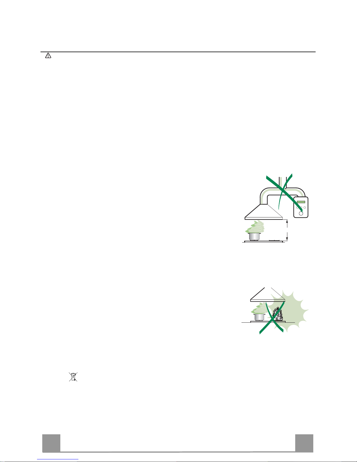
• The minimum safety distance between the cooker top and the extractor
hood is 650 mm (some models can be installed at a lower height, please refer to the paragraphs on working dimensions and installation).
• Check that the mains voltage corresponds to that indicated on the rating
plate fixed to the inside of the hood.
• For Class I appliances, check that the domestic power supply guarantees
adequate earthing.
Connect the extractor to the exhaust flue through a pipe of minimum diame-
ter 120 mm. The route of the flue must be as short as possible.
• Do not connect the extractor hood to exhaust ducts carrying combustion
fumes (boilers, fireplaces, etc.).
• If the extractor is used in conjunction with non-electrical appliances (e.g. gas
burning appliances), a sufficient degree of aeration must be guaranteed in
the room in order to prevent the backflow of exhaust gas. The kitchen must
have an opening communicating directly with the open air in order to
guarantee the entry of clean air.
USE
• The extractor hood has been designed exclusively for domestic use to eliminate kitchen smells.
• Never use the hood for purposes other than for which it has been designed.
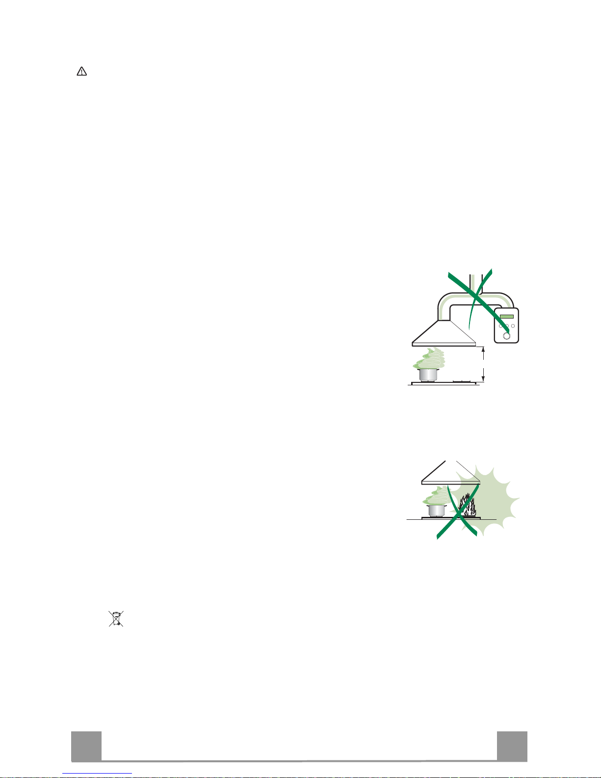
• Never leave high naked flames under the hood when it is in operation.
• Adjust the flame intensity to direct it onto the bottom of the pan only, making
sure that it does not engulf the sides.
• Deep fat fryers must be continuously monitored during use: overheated oil
can burst into flames.
• Do not flambè under the range hood; risk of fire
• This appliance is not intended for use by persons (including children) with
reduced physical, sensory or mental capabilities, or lack of experience and
knowledge, unless they have been given supervision or instruction concerning use of the appliance by a person responsible for their safety.
• Children should be supervised to ensure that they do not play with the appliance.
MAINTENANCE
• Switch off or unplug the appliance from the mains supply before carrying out
any maintenance work.
• Clean and/or replace the Filters after the specified time period (Fire hazard).
• Clean the hood using a damp cloth and a neutral liquid detergent.
The symbol on the product or on its packaging indicates that this product may not be treated
as household waste. Instead it shall be handed over to the applicable collection point for the
recycling of electrical and electronic equipment. By ensuring this product is disposed of correctly,
you will help prevent potential negative consequences for the environment and human health,
which could otherwise be caused by inappropriate waste handling of this product. For more
detailed information about recycling of this product, please contact your local city office, your
household waste disposal service or the shop where you purchased the product.
650 mm min.
Page 4

EN
4
4
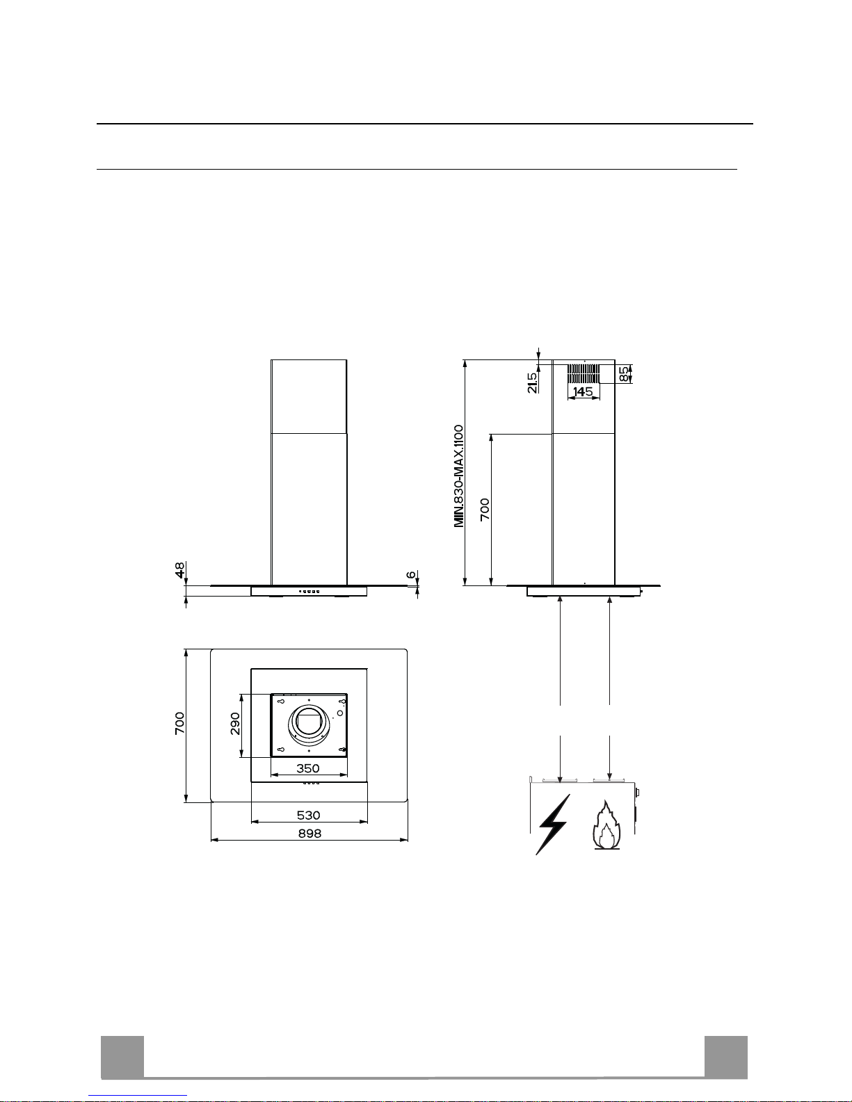
CHARACTERISTICS
Dimensions
Min.
650mm
Min.
650mm
Page 5
EN
5
5
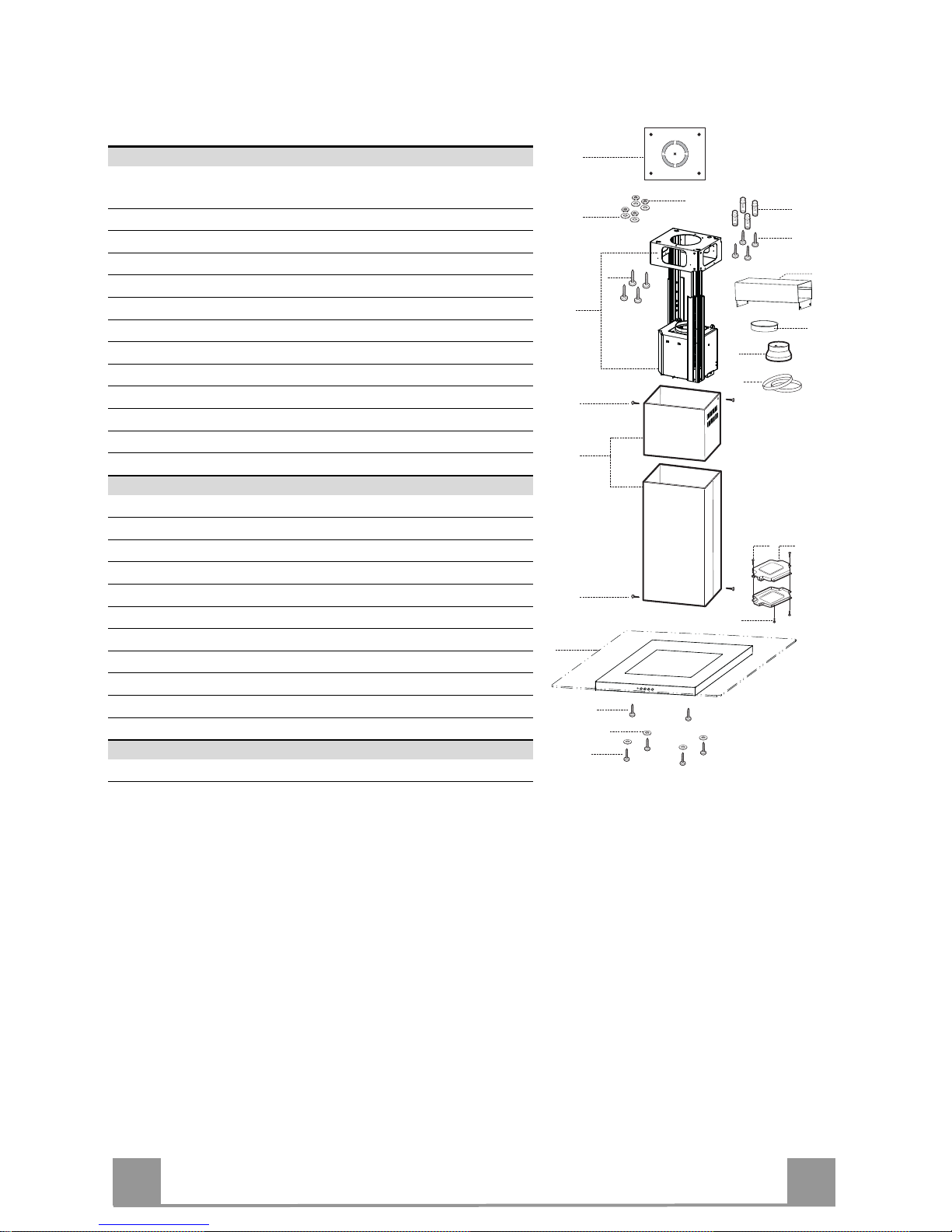
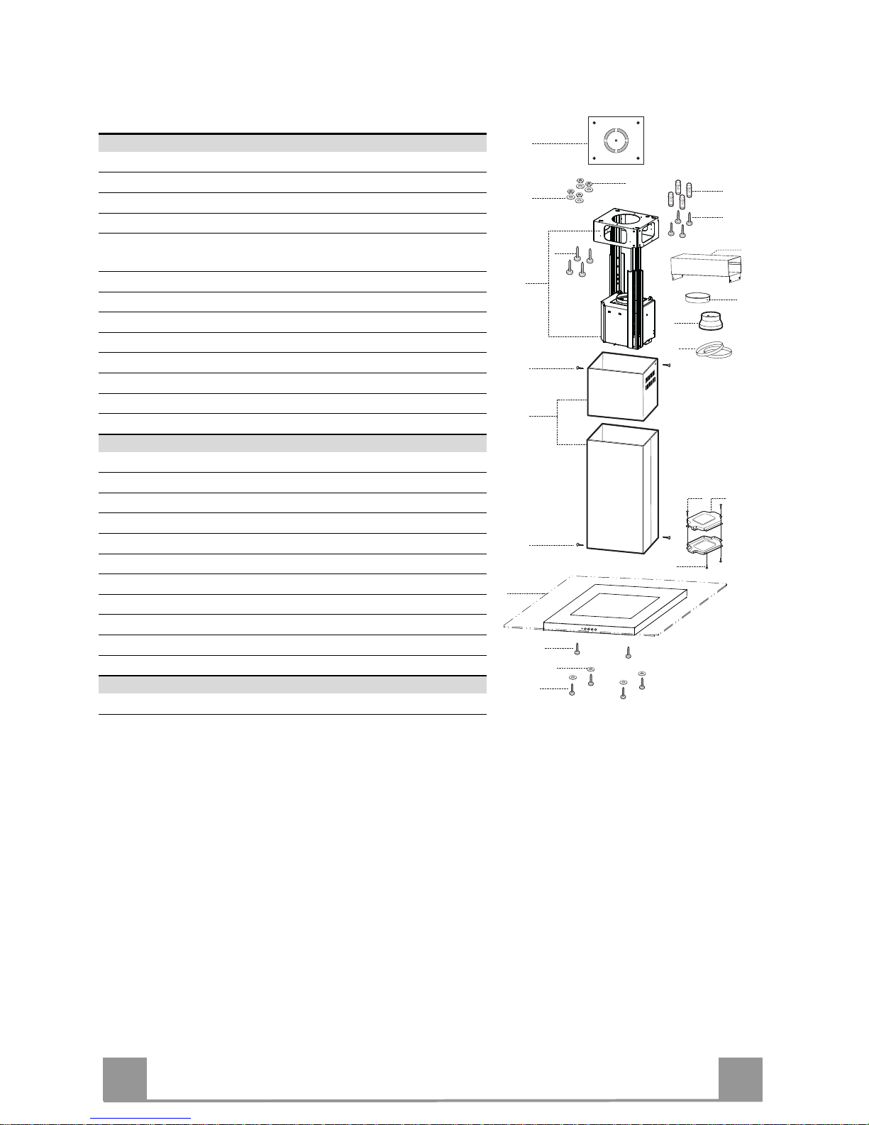
Components
Ref. Q.ty Product Components
1 1 Hood Body, complete with: Controls, Light, Blower,
Filters
2 1 Telescopic Chimney comprising:
2.1 1 Upper Section
2.2 1 Lower Section
7.1 1 Telescopic frame complete with extractor, consisting of:
7.1a 1 Upper frame
7.1b 1 Lower frame
9 1 Reducer Flange ø 150-120 mm
10 1 Flange ø 150
15 1 Air Outlet Connection
24 1 Junction box
25 Pipe clamps (not included)
Ref. Q.ty Installation Components
11 4 Wall Plugs ø 10
12c 6 Screws 2,9 x 6,5
12e 2 Screws 2,9 x 9,5
12f 2 Screws M4 x 80
12g 4 Screws M6 x 80
12h 4 Screws 5,2 x 70
12q 4 Screws 3,5 x 9,5
21 1 Drilling template
22 8 6.4 mm int. dia washers
23 4 M6 nuts
Q.ty Documentation
1 Instruction Manual
12c
7.1a
7.1
22
23
12h
7.1b
2
2.1
2.2
12c
11
21
12g
24
12e
15
12c
25
9
10
1
12f
12q
22
Page 6
EN
6
6
INSTALLATION
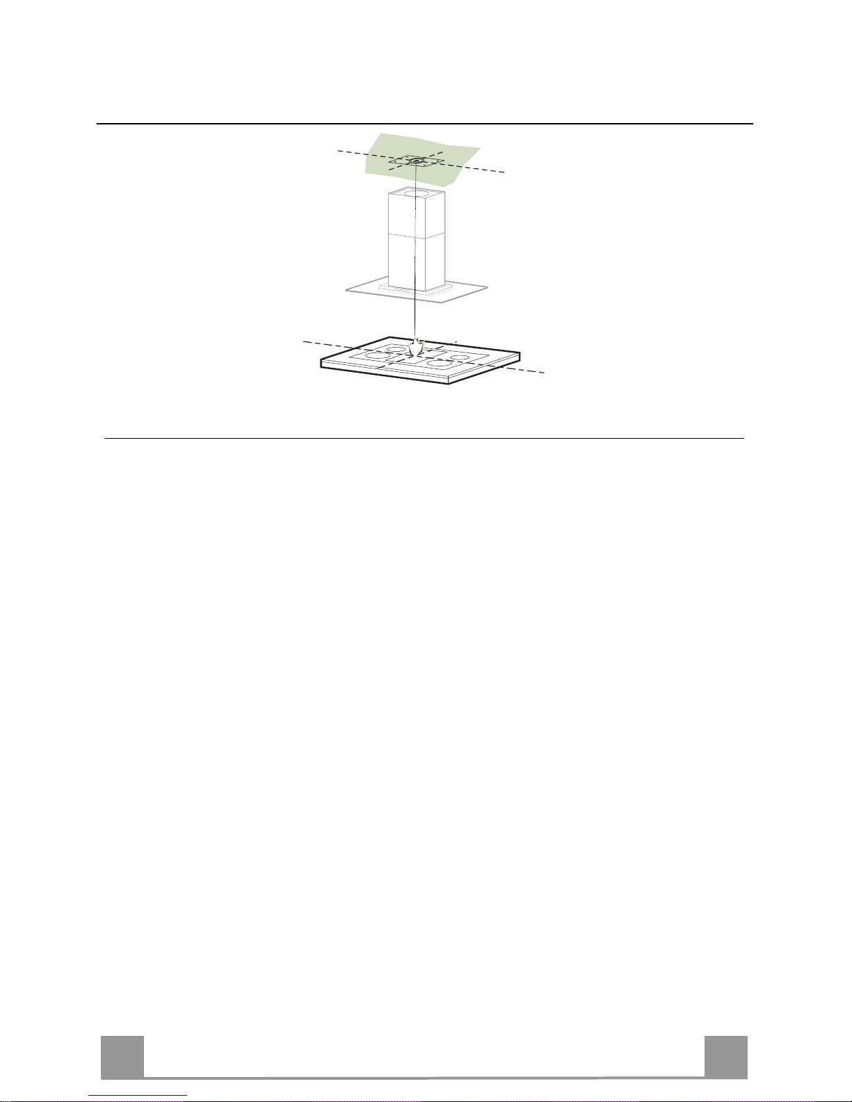
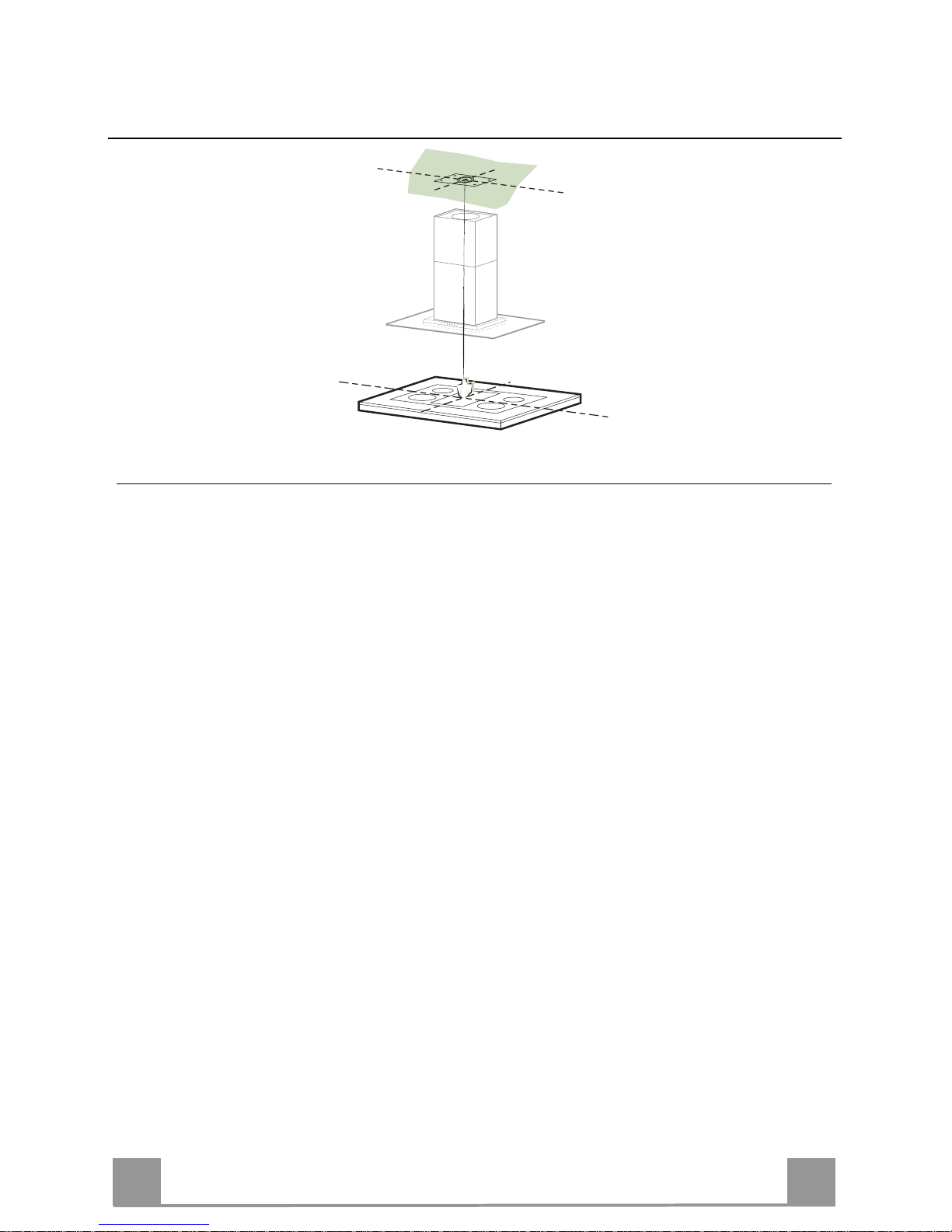
Drilling the Ceiling/shelf and fixing the frame
DRILLING THE CEILING/SHELF
• Use a plumb line to mark the centre of the hob on the ceiling/support shelf.
• Place the drilling template 21 provided on the ceiling/support shelf, making sure that the
template is in the correct position by lining up the axes of the template with those of the hob.
• Mark the centres of the holes in the template.
• Drill the holes at the points marked:
• For concrete ceilings, drill for plugs appropriate to the screw size.
• For hollow brick ceilings with wall thickness of 20 mm: drill ø 10 mm(immediately insert
the Dowels 11 supplied).
• For wooden beam ceilings, drill according to the wood screws used.
• For wooden shelf, drill ø 7 mm.
• For the power supply cable feed, drill ø 10 mm.
• For the air outlet (Ducted Version), drill according to the diameter of the external air ex-
haust duct connection.
• Insert two screws of the following type, crossing them and leaving 4-5 mm from the ceiling:
• For concrete ceilings, use the appropriate plugs for the screw size (not provided).
• for Cavity ceiling with inner space, with wall thickness of approx. 20 mm, Screws 12h,
supplied.
• For wooden beam ceilings, use 4 wood screws (not provided).
• For wooden shelf, use 4 screws 12g with washers 22 and nuts 23, provided.
Page 7
EN
7
7
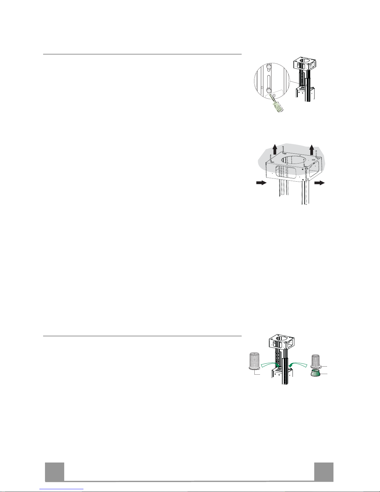
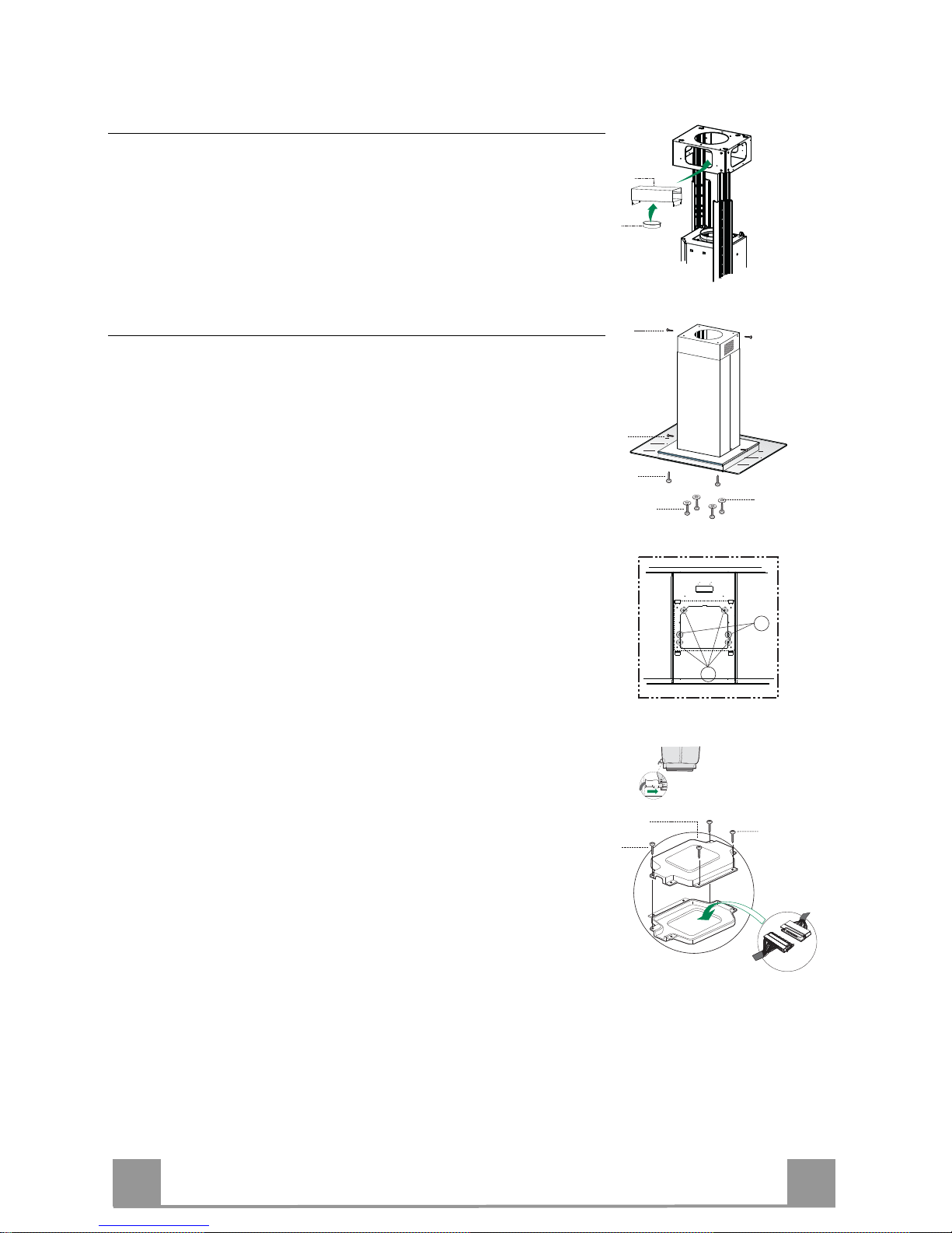
Fixing the frame
• Loosen the two screws fastening the lower chimney and remove this from the lower frame.
• Loosen the two screws fastening the upper chimney and remove this from the upper frame.
If you wish to adjust the height of the frame, proceed as follows:
• Unfasten the metric screws joining the two columns, located at
the sides of the frame.
• Adjust the frame to the height required, then refit all the screws
removed as above.
• Insert the upper chimney stack from above, and leave it running free on the frame.
• Lift up the frame, fit the frame slots onto the screws up to the
slot end positions.
• Tighten the two screws and fasten the other two screws provided with the hood.
Before tightening the screws completely it is possible to adjust
the frame by turning it. Make sure that the screws do not come
out of their seats in the slotted holes.
• The frame mountings must be secure to withstand the weight
of the hood and any stresses caused by the occasional side
thrust applied to the device.
On completion, check that the base is stable, even if the frame
is subjected to bending.
• In all cases where the ceiling is not strong enough at the suspension point, the installer must provide strengthening using
suitable plates and backing pieces anchored to the structurally
sound parts.
2
2
1
1
Ducted version air exhaust system Connection
When installing the ducted version, connect the hood to the
chimney using either a flexible or rigid pipe ø 150 or 120 mm,
the choice of which is left to the installer.
• To install a ø 120 mm air exhaust connection, insert the reducer flange 9 on the hood body outlet.
• Fix the pipe using the pipe clamps 25 (not provided).
• Remove any activated charcoal filters.
9
ø 150
ø 120
25
25
Page 8
EN
8
8
Recirculation version air outlet
• Fix the connection 15 to the frame using the 4 screws provided.
• Fix the flange 10 to the lower opening of the connection 15.
• Connect the hood air outlet to the flange in the lower part of
the junction using a rigid or flexible ø 150 tube (by installer’s
choice).
15
10
Flue assembly - Mounting the hood body
• Position the upper chimney section and fix the upper part to the
frame using the 2 screws 12c (2,9 x 6,5) provided.
• Similarly, position the lower chimney section and fix the
lower part to the frame using the 2 screws 12c (2,9 x 6,5) provided.
Before fixing the hood canopy to the frame:
• Screw the 2 screws 12f half way into the holes provided in the
sides of the bottom of the frame.
• Remove the grease filters from the hood canopy.
• Remove any activated charcoal filters.
• Lift the hood canopy and engage the screws 12f in the slots (A)
as far as they will go.
• Working from below, fix the hood canopy to the frame (B),
using the 4 screws 12q and 4 washers 22 provided, then tighten
all the screws securely.
A
B
12f
12q
12c
12c
22
ELECTRICAL CONNECTION
• Connect the hood to the mains through a two-pole switch having a contact gap of at least 3 mm.
• Remove the grease filters (see paragraph Maintenance) being
sure that the connector of the feeding cable is correctly inserted
in the socket placed on the side of the fan.
• Connect the control connector Cmd.
• Place the connectors in the junction box 24 and close it using
the 2 screws 12e (2,9 x 9,5) provided.
• Fix the junction box to the hood body using the 2 screws 12c
(2,9 x 6,5) provided.
• For the recirculation version, fit the activated carbon odour filter.
• Replace the grease filters.
24
12e
12c
Cmd
Page 9
EN
9
9
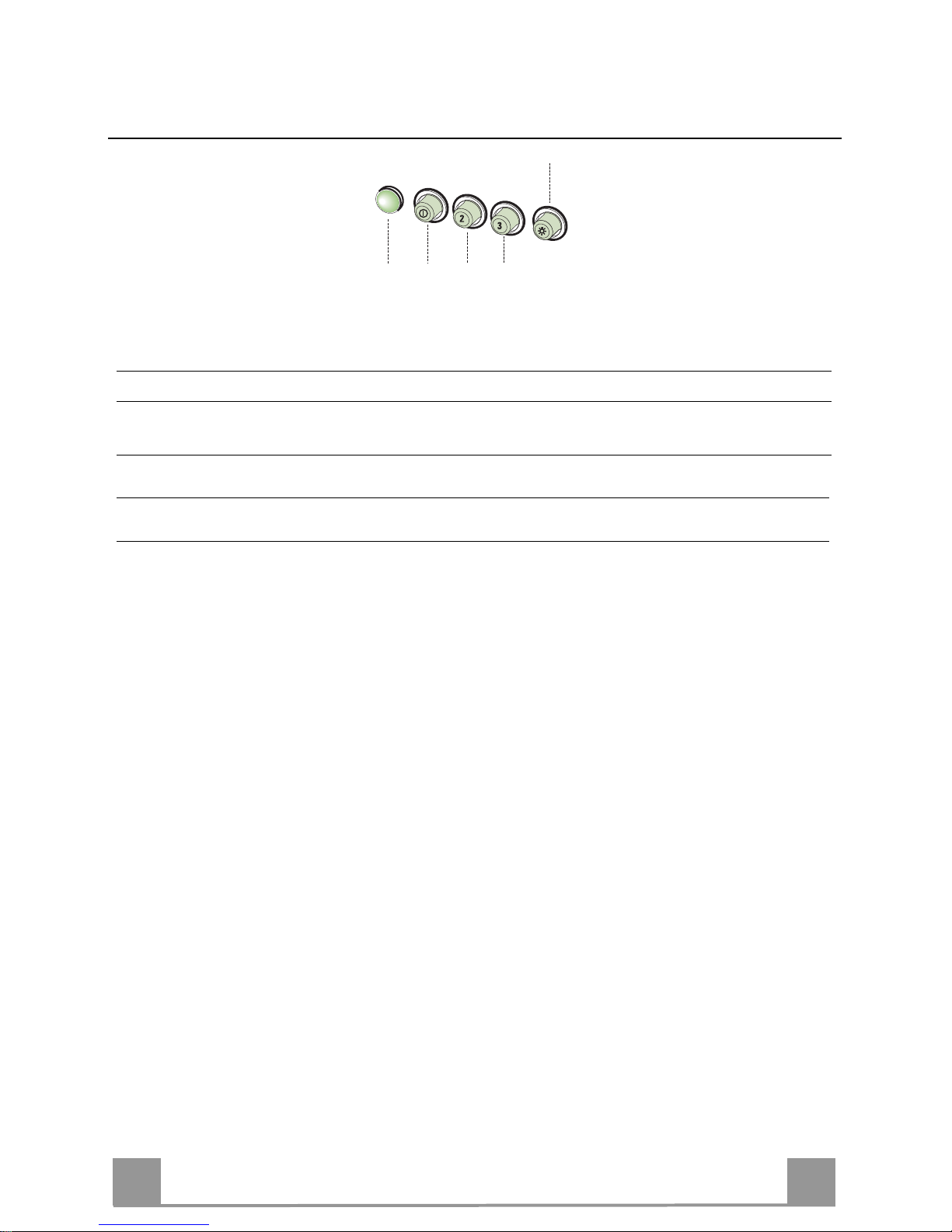
USE
L
V1 V2 V3
S
L Light Switches the lighting system on and off.
S Led Motor running led.
V1 Motor Switches the extractor motor on and off at low speed. Used to provide a
continuous and silent air change in the presence of light cooking vapours.
V2 Speed Medium speed, suitable for most operating conditions given the optimum
treated air flow/noise level ratio.
V3 Speed Maximum speed, used for eliminating the highest cooking vapour emission,
including long periods.
Page 10
EN
1
10
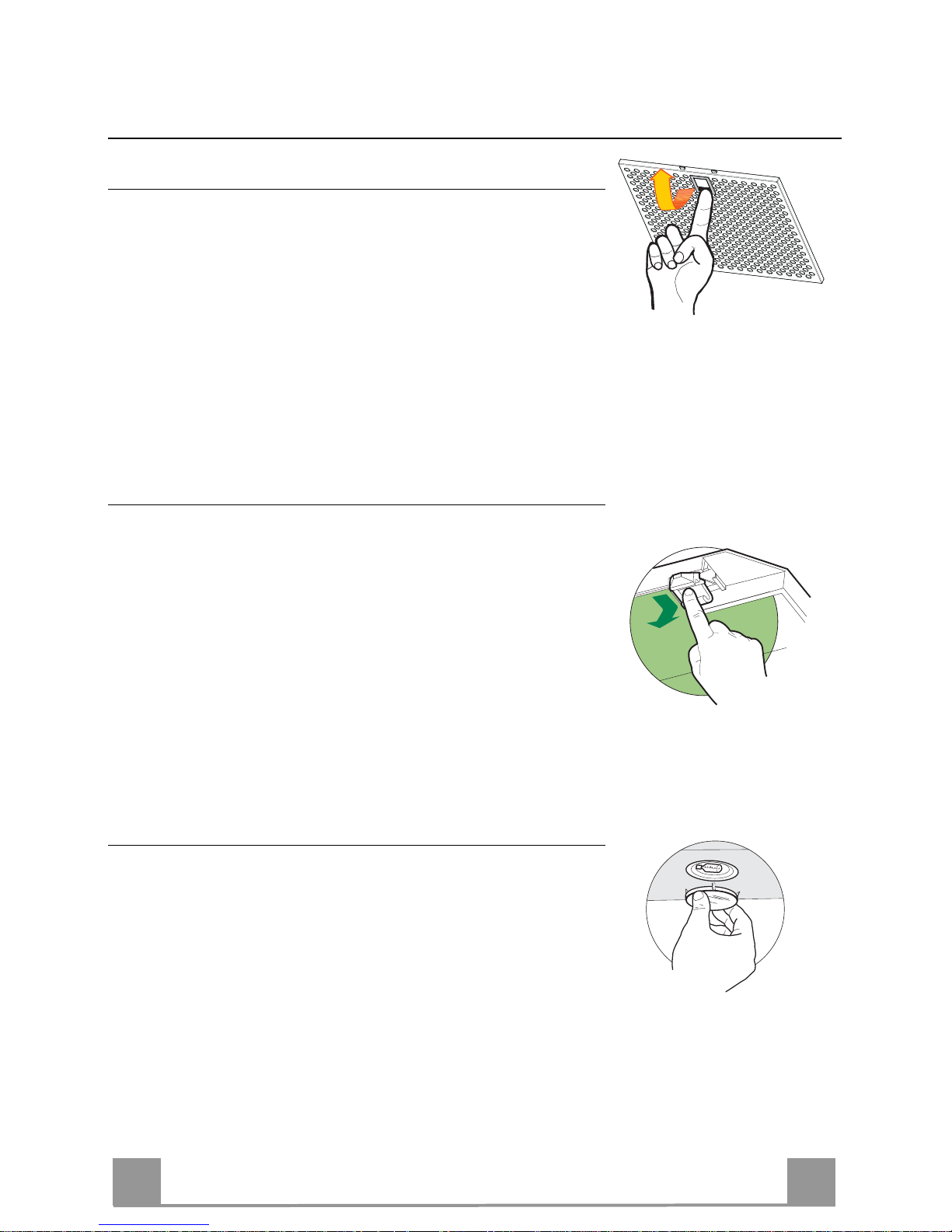
MAINTENANCE
Grease filters
CLEANING METAL SELF- SUPPORTING GREASE FILTERS
• The filters must be cleaned every 2 months of operation, or
more frequently for particularly heavy usage, and can be
washed in a dishwasher.
• Remove the filters one at a time holding them up with one
hand and pulling the handle downwards with the other hand at
the same time.
• Wash the filters, taking care not to bend them. Allow them to
dry before refitting.
• When refitting the filters, make sure that the handle is visible
on the outside.
Activated charcoal filter (Recirculation version)
REPLACING THE ACTIVATED CHARCOAL FILTER
• The filter is not washable and cannot be regenerated, and must
be replaced approximately every 4 months of operation, or
more frequently for particularly heavy usage.
• Remove the metal grease filters.
• Remove the saturated activated carbon filter by releasing the
fixing hooks.
• Fit the new filter by hooking it into its seating.
• Refit the metal grease filters.
Lighting
LIGHT REPLACEMENT
20 W halogen light.
• Remove the snap-on lamp cover by levering it from under the
metal ring, supporting it with one hand.
• Remove the halogen lamp from the lamp holder by pulling
gently.
• Replace the lamp with a new one of the same type, making
sure that you insert the two pins properly into the housings on
the lamp holder.
• Replace the snap-on lamp cover.
Page 11

IT
1
11
CONSIGLI E SUGGERIMENTI
Page 12
IT
1
12
Questo libretto di istruzioni per l'uso è previsto per più versioni dell' apparecchio.
É possibile che siano descritti singoli particolari della dotazione, che non riguardano il Vostro apparecchio.
INSTALLAZIONE
• Il produttore declina qualsiasi responsabilità per danni dovuti ad installazione non
corretta o non conforme alle regole dell’arte.
• La distanza minima di sicurezza tra il Piano di cottura e la Cappa deve essere di
650 mm, (alcuni modelli possono essere installati ad un’altezza inferiore, fare riferimento ai paragrafi ingombro e installazione).
• Verificare che la tensione di rete corrisponda a quella riportata nella targhetta
posta all’interno della Cappa.
• Per Apparecchi in Classe I
a
accertarsi che l’impianto elettrico domestico garanti-
sca un corretto scarico a terra.
• Collegare la Cappa all’uscita dell’aria aspirata con tubazione di diametro pari o
superiore a 120 mm. Il percorso della tubazione deve essere il più breve possibile.
• Non collegare la Cappa a condotti di scarico dei fumi prodotti da combustione
(caldaie, caminetti, ecc.).
• Nel caso in cui nella stanza vengano utilizzati sia la Cappa che apparecchi non
azionati da energia elettrica (ad esempio apparecchi utilizzatori di gas), si deve
provvedere ad una aerazione sufficiente dell’ambiente. Se la cucina ne fosse
sprovvista, praticare un’apertura che comunichi con l’esterno, per garantire il richiamo d’aria pulita.
USO
• La Cappa è stata progettata esclusivamente per uso domestico, per abbattere gli
odori della cucina.
• Non fare mai uso improprio della Cappa.
• Non lasciare fiamme libere a forte intensità sotto la Cappa in funzione.
• Regolare sempre le fiamme in modo da evitare una evidente fuoriuscita laterale
delle stesse rispetto al fondo delle pentole.
• Controllare le friggitrici durante l’uso: l’olio surriscaldato potrebbe infiammarsi.
• Non preparare alimenti flambè sotto la cappa da cucina; pericolo d'incendio.
• Questo apparecchio non deve essere utilizzato da persone (bambini inclusi) con
ridotte capacità psichiche, sensoriali o mentali, oppure da persone senza esperienza e conoscenza, a meno che non siano controllati o istruiti all’uso
dell’apparecchio da persone responsabili della loro sicurezza.
• I bambini devono essere supervisionati per assicurarsi che non giochino con
l’apparecchio.
MANUTENZIONE
• Prima di procedere a qualsiasi operazione di manutenzione, disinserire la Cappa
togliendo la spina elettrica o spegnendo l’interruttore generale.
• Effettuare una scrupolosa e tempestiva manutenzione dei Filtri secondo gli intervalli consigliati (Rischio di incendio).
• Per la pulizia delle superfici della Cappa è sufficiente utilizzare un panno umido e
detersivo liquido neutro.
Il simbolo sul prodotto o sulla confezione indica che il prodotto non deve essere considerato
come un normale rifiuto domestico, ma deve essere portato nel punto di raccolta appropriato per
il riciclaggio di apparecchiature elettriche ed elettroniche. Provvedendo a smaltire questo prodotto in modo appropriato, si contribuisce a evitare potenziali conseguenze negative per l’ambiente
e per la salute, che potrebbero derivare da uno smaltimento inadeguato del prodotto. Per informazioni più dettagliate sul riciclaggio di questo prodotto, contattare l’ufficio comunale, il servizio
locale di smaltimento rifiuti o il negozio in cui è stato acquistato il prodotto.
650 mm min.
Page 13
IT
1
13
CARATTERISTICHE
Ingombro
Min.
650mm
Min.
650mm
Page 14
IT
1
14
Componenti
Rif. Q.tà Componenti di Prodotto
1 1 Corpo Cappa completo di: Comandi, Luce, Filtri
2 1 Camino telescopico formato da:
2.1 1 Camino superiore
2.2 1 Camino inferiore
7.1 1 Traliccio telescopico completo di Aspiratore, formato
da:
7.1a 1 Traliccio superiore
7.1b 1 Traliccio inferiore
9 1 Flangia di riduzione ø 150-120 mm
10 1 Flangia ø 150
15 1 Raccordo Uscita Aria
24 1 Scatola connessioni
25 Fascette stringitubo (non incluse)
Rif. Q.tà Componenti di Installazione
11 4 Tasselli ø 10
12c 6 Viti 2,9 x 6,5
12e 2 Viti 2,9 x 9,5
12f 2 Viti M4 x 80
12g 4 Viti M6 x 80
12h 4 Viti 5,2 x 70
12q 4 Viti 3,5 x 9,5
21 1 Dima di foratura
22 8 Rondelle ø 6,4
23 4 Dadi M6
Q.tà Documentazione
1 Libretto Istruzioni
12c
7.1a
7.1
22
23
12h
7.1b
2
2.1
2.2
12c
11
21
12g
24
12e
15
12c
25
9
10
1
12f
12q
22
Page 15
IT
1
15
INSTALLAZIONE
Foratura Soffitto/Mensola e Fissaggio Traliccio
FORATURA SOFFITTO/MENSOLA
• Con l’ausilio di un Filo a piombo riportare sul Soffitto/Mensola di supporto il centro del
Piano di Cottura.
• Appoggiare al Soffitto/Mensola la Dima di Foratura 21 in dotazione, facendo coincidere il
suo centro al centro proiettato e allineando gli assi della Dima agli assi del Piano di Cottura.
• Segnare i centri dei Fori della Dima.
• Forare i punti seguenti:
• Soffitto in Calcestruzzo massiccio: secondo Tasselli per Calcestruzzo impiegati.
• Soffitto in Laterizio a camera d’aria, con spessore resistente di 20 mm: ø 10 mm (inserire
subito i Tasselli 11 in dotazione).
• Soffitto in Travatura di Legno: secondo Viti per Legno impiegate.
• Mensola in Legno: ø 7 mm.
• Passaggio del Cavo elettrico di Alimentazione: ø 10 mm.
• Uscita Aria (Versione Aspirante): secondo diametro del collegamento alla Tubazione di
Evacuazione Esterna.
• Avvitare, incrociandole e lasciando 4-5 mm dal soffitto, due viti:
• per Calcestruzzo massiccio, Tasselli per Calcestruzzo, non in dotazione.
• per Laterizio a camera d’aria, con spessore resistente di 20 mm circa, Viti 12h, in dotazio-
ne.
• per Travatura di legno, Viti per legno, non in dotazione.
• per Mensola in Legno, viti 12g con Rondelle 22 e Dadi 23, in dotazione.
Page 16

IT
1
16
Fissaggio Traliccio
• Svitare le due viti che fissano il camino inferiore e sfilarlo dal
traliccio (dalla parte inferiore).
• Svitare le due viti che fissano il camino superiore e sfilarlo dal
traliccio (dalla parte superiore).
Nel caso in cui si voglia regolare l’altezza del traliccio procedere
come segue:
• Svitare le viti metriche che uniscono le due colonne, poste ai
lati del traliccio;
• Regolare l’altezza desiderata del traliccio e riavvitare le viti
precedentemente tolte;
• Inserire il camino superiore dall’ alto e lasciarlo libero sul traliccio;
• Sollevare il traliccio, incastrare le asole sulle viti e scorrere
fino a battuta;
• Stringere le due viti e avvitare le altre due in dotazione;
Prima di serrare definitivamente le viti è possibile effettuare delle
regolazioni spostando il traliccio, facendo attenzione che le viti
non escano dalla sede dell’asola di regolazione.
• Il fissaggio del Traliccio deve essere sicuro in relazione sia al
peso della Cappa sia alle sollecitazioni causate da occasionali
spinte laterali all’Apparecchio montato. A fissaggio avvenuto
verificare quindi che la base sia stabile anche se il Traliccio è
sollecitato a flessione.
• In tutti i casi in cui il Soffitto non fosse sufficientemente robusto sul punto di sospensione, l’Installatore dovrà provvedere a
irrobustirlo con opportune piastre e contropiastre ancorate a
parti strutturalmente resistenti.
2
2
1
1
Connessione Uscita aria Versione Aspirante
Per installazione in Versione Aspirante collegare la Cappa alla
tubazione di uscita per mezzo di un tubo rigido o flessibile di
ø 150 o 120 mm, la cui scelta è lasciata all’installatore.
• Per collegamento con tubo ø 120 mm, inserire la Flangia di
riduzione 9 sull’Uscita del Corpo Cappa.
• Fissare il tubo con adeguate fascette stringitubo 25(non incluse).
• Rimuovere eventuali filtri al carbone attivo.
9
ø 150
ø 120
25
25
Page 17

IT
1
17
Uscita aria Versione Filtrante
• Fissare il Raccordo 15 al traliccio utilizzando le 4 Viti in dotazione.
• Incastrare la flangia 10 nell’apposito foro inferiore del Raccordo 15.
• Collegare l’uscita aria della cappa con la flangia posta sotto al
raccordo per mezzo di un tubo rigido o flessibile ø 150mm , la
cui scelta è lasciata all’installatore
15
10
Montaggio Camino e Fissaggio Corpo Cappa
• Posizionare il Camino superiore e fissare nella parte superiore
al Traliccio con 2 Viti 12c (2,9 x 6,5) in dotazione.
• Analogamente posizionare il Camino inferiore e fissare nella
parte inferiore al Traliccio con 2 Viti 12c (2,9 x 6,5) in dotazione.
Prima di fissare il Corpo Cappa al Traliccio:
• Avvitare per metà le 2 Viti 12f sulla parte inferiore del traliccio
in posizione laterale in corrispondenza dei 2 fori predisposti.
• Togliere i Filtri antigrasso dal Corpo Cappa;
• Togliere eventuali Filtri Antiodore al Carbone attivo.
• Sollevare il Corpo Cappa e incastrare le Viti 12f sulle asole
(rif.A) fino a battuta.
• Fissare da sotto con 4 Viti 12q e 4 Rondelle 22 in dotazione il
Corpo Cappa al Traliccio predisposto (rif.B) e serrare definitivamente tutte le Viti.
A
B
12f
12q
12c
12c
22
CONNESSIONE ELETTRICA
• Collegare la Cappa all’Alimentazione di Rete interponendo un
Interruttore bipolare con apertura dei contatti di almeno 3 mm.
• Rimuovere i Filtri antigrasso (vedi par. “Manutenzione”) e assicurarsi che il connettore del Cavo di alimentazione sia correttamente inserito nella presa dell’Aspiratore
• Collegare il Connettore dei Comandi Cmd.
• Riporre entrambi i Connettori nella Scatola di protezione 24
chiudendola con 2 Viti 12e(2,9 x 9,5) in dotazione.
• Fissare la Scatola di protezione al Corpo Cappa con 2 Viti 12c
(2,9 x 6,5) in dotazione.
• Per la Versione Filtrante montare il Filtro Antiodore al Carbone attivo.
• Rimontare i Filtri Antigrasso.
24
12e
12c
Cmd
Page 18

IT
1
18
USO
L
V1 V2 V3
S
L Luci Accende e spegne l’Impianto di Illuminazione.
S Led Led accensione Motore.
V1 Motore Accende e spegne il motore Aspirazione a velocità minima, adatta ad un
ricambio d’aria continuo particolarmente silenzioso, in presenza di pochi
vapori di cottura.
V2 Velocità Velocità media, adatta alla maggior parte delle condizioni d’uso, dato
l’ottimo rapporto tra portata d’aria trattata e livello sonoro.
V3 Velocità Velocità massima, adatta a fronteggiare le massime emissioni di vapore di
cottura, anche per tempi prolungati.
Page 19

IT
1
19
MANUTENZIONE
Filtri antigrasso
PULIZIA FILTRI ANTIGRASSO METALLICI AUTOPORTANTI
• Sono lavabili anche in lavastoviglie, e necessitano di essere
lavati ogni 2 mesi circa di utilizzo o più frequentemente, per un
uso particolarmente intenso.
• Togliere i Filtri uno alla volta,sostenendoli con una mano mentre con l’altra si tira la leva verso il basso.
• Lavare i Filtri evitando di piegarli, e lasciarli asciugare prima
di rimontarli.
• Rimontarli facendo attenzione a mantenere la maniglia verso la
parte visibile esterna
Filtro antiodore (Versione Filtrante)
SOSTITUZIONE FILTRO ANTIODORE AL CARBONE ATTIVO
• Non è lavabile e non è rigenerabile, va sostituito almeno ogni 4
mesi o più frequentemente, per un uso particolarmente intenso.
• Togliere i Filtri antigrasso metallici.
• Rimuovere il Filtro antiodore al Carbone attivo saturo, agendo
sugli appositi agganci.
• Montare il nuovo Filtro agganciandolo nella sua sede.
• Rimontare i Filtri antigrasso metallici.
Illuminazione
SOSTITUZIONE LAMPADE
Lampade alogene da 20 W
• Togliere il bloccavetro metallico a pressione facendo leva sotto
la ghiera, sostenendolo con una mano.
• Estrarre la lampadina alogena dal portalampada.
• Sostituirla con una nuova lampadina di uguali caratteristiche,
facendo attenzione ad inserire correttamente i due spinotti nella
sede del portalampade.
• Rimontare il bloccavetro a pressione.
Page 20

FR
2
20
CONSEILS ET SUGGESTIONS
La présente notice d'emploi vaut pour plusieurs versions de l'appareil. Elle peut conte-
nir des descriptions d'accessoires ne figurant pas dans votre appareil.
INSTALLATION
• Le fabricant décline toute responsabilité en cas de dommage dû à une installation non
correcte ou non conforme aux règles de l’art.
• La distance minimale de sécurité entre le plan de cuisson et la hotte doit être de 650
mm au moins (certains modèles peuvent être installés à une hauteur inférieure : se reporter aux paragraphes « Encombrement » et « Installation »).
• Vérifier que la tension du secteur correspond à la valeur qui figure sur la plaquette
apposée à l’intérieur de la hotte.
• Pour les Appareils appartenant à la Ière Classe, veiller à ce que la mise à la terre de
l’installation électrique domestique ait été effectuée conformément aux normes en vigueur.
• Connecter la hotte à la sortie d’air aspiré à l’aide d’une tuyauterie d’un diamètre égal ou
supérieur à 120 mm. Le parcours de la tuyauterie doit être le plus court possible.
• Ne pas connecter la hotte à des conduites d’évacuation de fumées issues d’une combustion tel que (Chaudière, cheminée, etc…).
• Si vous utilisez des appareils qui ne fonctionnent pas à l’électricité dans la pièce ou est
installée la hotte (par exemple: des appareils fonctionnant au gaz), vous devez prévoir
une aération suffisante du milieu. Si la cuisine en est dépourvue, pratiquez une ouverture qui communique avec l’extérieur pour garantir l’infiltration de l’air pur.
UTILISATION
• La hotte a été conçue exclusivement pour l’usage domestique, dans le but d’éliminer
les odeurs de la cuisine.
• Ne jamais utiliser abusivement la hotte.
• Ne pas laisser les flammes libres à forte intensité quand la hotte est en service.
• Toujours régler les flammes de manière à éviter toute sortie latérale de ces dernières
par rapport au fond des marmites.
• Contrôler les friteuses lors de l’utilisation car l’huile surchauffée pourrait s’enflammer.
• Ne pas préparer d’aliments flambés sous la hotte de cuisine : risque d’incendie
• Cet appareil ne doit pas être utilisé par des personnes (y compris les enfants) ayant
des capacités psychiques, sensorielles ou mentales réduites, ni par des personnes
n’ayant pas l’expérience et la connaissance de ce type d’appareils, à moins d'être sous
le contrôle et la formation de personnes responsables de leur sécurité.
• Les enfants doivent être surveillés pour s'assurer qu'ils ne jouent pas avec l'appareil.
ENTRETIEN
• Avant de procéder à toute opération d’entretien, retirer la hotte en retirant la fiche ou en
actionnant l’interrupteur général.
• Effectuer un entretien scrupuleux et en temps dû des Filtres, à la cadence conseillée
(Risque d’incendie).
• Pour le nettoyage des surfaces de la hotte, il suffit d’utiliser un chiffon humide et détersif liquide neutre.
Le symbole sur le produit ou son emballage indique que ce produit ne peut être traité comme
déchet ménager. Il doit plutôt être remis au point de ramassage concerné, se chargeant du recyclage du matériel électrique et électronique. En vous assurant que ce produit est éliminé correctement, vous favorisez la prévention des conséquences négatives pour l’environnement et la santé
humaine qui, sinon, seraient le résultat d’un traitement inapproprié des déchets de ce produit. Pour
obtenir plus de détails sur le recyclage de ce produit, veuillez prendre contact avec le bureau municipal de votre région, votre service d’élimination des déchets ménagers ou le magasin où vous avez
acheté le produit.
650 mm min.
Page 21

FR
2
21
CARACTERISTIQUES
Encombrement
Min.
650mm
Min.
650mm
Page 22

FR
2
22
Composants
Réf. Q.té Composants de Produit
1 1 Corps Hotte équipé de: Comandes, Lumière, Filtres
2 1 Cheminée Télescopique formée de :
2.1 1 Cheminée Supérieure
2.2 1 Cheminée Inférieure
7.1 1 Treillis télescopique avec Aspirateur, formé par:
7.1a 1 Treillis supérieur
7.1b 1 Treillis inférieur
9 1 Flasque de Réduction ø 150-120 mm
10 1 Flasque ø 150
15 1 Raccord Sortie Air
24 1 Boîte connexions
25 Colliers de serrage serre-tube (non compris)
Réf. Q.té Composants pour l’installation
11 4 Chevilles ø 10
12c 6 Vis 2,9 x 6,5
12e 2 Vis 2,9 x 9,5
12f 2 Vis M4 x 80
12g 4 Vis M6 x 80
12h 4 Vis 5,2 x 70
12q 4 Vis 3,5 x 9,5
21 1 Gabarit de perçage
22 8 Rondelles øi 6,4
23 4 Écrous M6
Q.té Documentation
1 Manuel d’instructions
12c
7.1a
7.1
22
23
12h
7.1b
2
2.1
2.2
12c
11
21
12g
24
12e
15
12c
25
9
10
1
12f
12q
22
Page 23

FR
2
23
INSTALLATION
Perçage Plafond/Étagère et Fixation Treillis
PERÇAGE PLAFOND/ETAGERE
• À l’aide d’un Fil à plomb, reporter sur le Plafond/Étagère de support le centre du Plan de
Cuisson.
• Poser contre le Plafond/Étagère le Gabarit de Perçage 21 fourni avec l’appareil, en faisant
coïncider son centre avec le centre projeté et en alignant les axes du Gabarit avec les axes du
Plan de Cuisson.
• Marquer les centres des Trous du Gabarit.
• Percer les trous qui ont été marqués:
• Plafond en Béton massif: en fonction des Goujons pour Béton utilisés.
• Plafond en Briques avec chambre à air, avec épaisseur résistante de 20 mm: ø 10 mm (in-
sérer immédiatement les Chevilles 11 fournies avec l’appareil).
• Plafond en Poutrage en Bois: en fonction des Vis à Bois utilisées.
• Étagère en Bois: ø 7 mm.
• Passage du Câble électrique d’Alimentation: ø 10 mm.
• Sortie Air (Version Aspirante): en fonction du diamètre de la connexion avec les Tuyaux
d’Évacuation Externe.
• Visser deux vis en les croisant et en laissant 4-5 mm. de distance par rapport au plafond:
• pour le Béton massif, des Goujons pour Béton, non fournis avec l’appareil.
• pour Briques percées, ayant une épaisseur résistante de 20 mm. environ, utiliser les Vis
12h, fournies avec l'appareil.
• pour le Poutrage en bois, 4 Vis à bois, non fournies avec l’appareil.
• pour l’Étagère en Bois, 4 Vis 12g avec Rondelles 22 et Écrous 23, fournis avec l’appareil.
Page 24

FR
2
24
FiXATION TREILLIS
• Dévisser les deux vis qui fixent la cheminée inférieure et sortir
cette dernière du treillis (depuis la partie inférieure).
• Dévisser les deux vis qui fixent la cheminée supérieure et sortir
cette dernière du treillis (depuis la partie supérieure).
Si l’on souhaite régler la hauteur du treillis, effectuer les opérations suivantes:
• Dévisser les vis métriques qui unissent les deux colonnes, qui
se trouvent sur les côtés du treillis.
• Régler la hauteur souhaitée du treillis et revisser les vis qui ont
été précédemment retirées.
• Insérer la cheminée supérieure depuis le haut et la laisser libre
sur le treillis.
• Soulever le treillis, encastrer les oeillets sur les vis et faire coulisser jusqu’à la butée;
• Serrer les deux vis et visser les autres deux vis fournies avec
l’appareil;
Avant de serrer définitivement les vis, il est possible d’effectuer
des réglages, en déplaçant le treillis, tout en contrôlant que les vis
ne sortent pas du logement de l’œillet de réglage.
• La fixation du Treillis doit être solide, en fonction du poids de
la Hotte et des contraintes provoquées par les poussées latérales occasionnelles auxquelles l’Appareil monté sera soumis.
Après avoir effectué la fixation, vérifier que la base soit stable,
même si le Treillis est soumis à des contraintes de flexion.
• Dans tous les cas où le Plafond ne devait pas être suffisamment
robuste en correspondance du point d’accrochage, l’Installateur
devra se charger de le rendre plus solide au moyen de plaques
et contre-plaques spéciales, ancrées sur les parties structuralement résistantes.
2
2
1
1
SORTIE AIR VERSION ASPIRANTE
En cas d’installation en version aspirante, brancher la hotte à la
tuyauterie de sortie via un tube rigide ou flexible de ø 150 ou 120
mm, au choix de l’installateur.
• En cas de branchement avec un tube de ø120 mm, insérer le
flasque de réduction 9 sur la sortie du corps de la hotte.
• Fixer le tuyau à l’aide des Colliers de serrage serre-tube 25 (ne
fournis pas).
• Retirer les éventuels filtres anti-odeur au charbon actif.
9
ø 150
ø 120
25
25
Page 25

FR
2
25
Sortie air version Recyclage
• Fixer le raccord 15 au Treillis à l’aide des 4 Vis fournies avec
l’appareil.
• Bloquer la bride 10 dans le trou inférieur de le raccord 15.
• Joindre la sortie d’air de la hotte avec la bride placée sous la
rallonge par un tuyau rigide ou flexible ø 150 ( le choix est de
l’installateur).
15
10
Montage Cheminée - Montage Corps Hotte
• Positionner la Cheminée supérieure et fixer cette dernière dans
la partie supérieure du Treillis à l’aide de 2 Vis 12c (2,9 x 6,5)
fournies avec l’appareil.
• De la même façon, positionner la Cheminée inférieure et fixer
cette dernière dans la partie inférieure du Treillis à l’aide de 2
Vis 12c (2,9 x 6,5) fournies avec l’appareil.
Avant de fixer le corps de la hotte au treillis :
• Visser à mi-course les 2 vis 12f sur la partie inférieure du treillis en
position latérale en correspondance des 2 trous prévus.
• Retirer les filtres à graisse du corps de la hotte.
• Retirer les éventuels filtres anti-odeur au charbon actif.
• Soulever le corps de la hotte et emboîter les vis 12f dans leur trou
(réf.A) jusqu’en butée.
• En passant par dessous, fixer avec les 4 vis 12q et les 4 rondelles 22
fournies le corps de la hotte au treillis prévu (réf.B) et serrer définitivement toutes les vis.
A
B
12f
12q
12c
12c
22
BRANCHEMENT ELECTRIQUE
• Brancher la hotte sur le secteur en interposant un interrupteur
bipolaire avec ouverture des contacts d’au moins 3 mm.
• Enlever les filtres à graisse (voir "Entretien") et s'assurer que le
connecteur du câble d'alimentation soit bien branché dans la
prise du diffuseur.
• Connecter le Connecteur des Commandes Cmd.
• Ranger les Connecteurs dans la Boîte de protection 24 en la
fermant à l’aide des 2 Vis 12e (2,9 x 9,5) fournies avec
l’appareil.
• Fixer la Boîte de protection au Corps de la Hotte à l’aide des 2
Vis 12c (2,9 x 6,5) fournies avec l’appareil.
• Pour la Version Filtrante, monter le Filtre Anti-odeur au Charbon actif.
• Remonter les Filtres Anti-graisse.
24
12e
12c
Cmd
Page 26

FR
2
26
UTILISATION
L
V1 V2 V3
S
L Lumières Allume et éteint l’installation de l’éclairage.
S Del Del allumage Moteur.
V1 Moteur Met en marche et à l’arrêt le moteur aspiration à vitesse minimale, pour un
rechange d’air permantent particulièrement silencieux en cas de faibles vapeurs de cuisson.
V2 Vitesse Vitesse moyenne pour la plupart des conditions d’utilisation, étant donné le
rapport optimal entre débit d’air traité et niveau sonore.
V3 Vitesse Vitesse maximum, pour faire face aux émissions maximum de vapeur de
cuisson, même pendant des temps prolongés.
Page 27

FR
2
27
ENTRETIEN
Filtres anti-graisse
NETTOYAGE FILTRES ANTI-GRAISSE METALLIQUES AUTOPORTEURS
• Lavables au lave-vaisselle, ils doivent être lavés environ tous
les 2 mois d’emploi ou plus fréquemment en cas d’emploi particulièrement intense.
• Enlevez les filtres l’un après l’autre en les soutenant avec une
main et en tirant en même temps la poignée vers le bas avec
l’autre main.
• Laver les filtres en évitant de les plier et les laisser sécher avant
de les remonter.
• Remonter les filtres en veillant à ce que la poignée reste vers la
partie visible externe
Filtre anti-odeur (Version filtrante)
REMPLACEMENT FILTRE AU CHARBON ACTIF
• Ni lavable, ni régénérable, le remplacer au moins tous les 4
mois d’emploi ou plus fréquemment en cas d’emploi particulièrement intense.
• Retirer les filtres anti-graisse métalliques.
• Retirer le filtre anti-odeur au charbon actif colmaté, en agissant
sur les crochets prévus à cet effet.
• Monter le nouveau filtre anti-odeur au charbon actif.
• Remonter les filtres anti-graisse métalliques.
Eclairage
REMPLACEMENT LAMPES
Lampe halogène de 20 W.
• Enlever le dispositif métallique de blocage du verre par encliquetage en exerçant une pression sous l’embout en le soutenant
d’une main.
• Extraire la lampe du support
• Remplacer la lampe par une nouvelle ayant le mêmes caractéristiques, en prenant soin d'insérer correctement les deux fiches
dans le support.
• Remonter le dispositif de blocage du verre par encliquetage.
Page 28

DE
2
28
EMPFEHLUNGEN UND HINWEISE
Diese Gebrauchsanleitung gilt für mehrere Geräte-Ausführungen. Es ist möglich, dass
einzelne Ausstattungsmerkmale beschrieben sind, die nicht auf Ihr Gerät zutreffen.
MONTAGE
• Der Hersteller haftet nicht für Schäden, die auf eine fehlerhafte und unsachgemäße Montage zurückzuführen sind.
• Der minimale Sicherheitsabstand zwischen Kochmulde und Haube muss 650 mm betragen (einige Modelle können an einer geringeren Höhe installiert werden, beziehen Sie sich
dazu auf den Absatz Raumbedarf und Installation).
• Prüfen, ob die Netzspannung mit dem Wert auf dem im Haubeninneren angebrachten Schild übereinstimmt.
• Bei Geräten der Klasse I ist sicherzustellen, dass die elektrische Anlage des Wohnhauses
über eine vorschriftsmäßige Erdung verfügt.
• Das Anschlussrohr der Haube zur Luftaustrittsöffnung muss einen Durchmesser von 120
mm oder darüber aufweisen. Der Rohrverlauf muss so kurz wie möglich sein.
• Die Haube darf an keine Entlüftungsschächte angeschlossen werden, in die Verbrennungsgase (Heizkessel, Kamine usw.) geleitet werden.
• Werden im Raum außer der Dunstabzugshaube andere, nicht elektrisch betriebene (z.B.
gasbetriebene) Geräte verwendet, muss für eine ausreichende Belüftung gesorgt werden.
Sollte die Küche diesbezüglich nicht entsprechen, ist an einer Aussenwand eine Öffnung
anzubringen, die Frischluftzufuhr gewährleistet.
BEDIENUNG
• Die Dunstabzugshaube ist ausschließlich zum Einsatz im privaten Haushalt und zur
Beseitigung von Küchengerüchen vorgesehen.
• Unsachgemäßer Einsatz der Haube ist zu unterlassen.
• Große Flammen bei eingeschalteter Haube niemals unbedeckt lassen.
Achtung! Große Flammen bei eingeschalteter Haube niemals unbedeckt lassen.
• Die Intensivität der Flamme ist so zu regulieren, dass sie den Topfboden nicht überragt.
Achtung! Frittiergeräte müssen während des Gebrauchs stets beaufsichtigt wer-
den: Überhitztes Öl kann sich entzünden.
• Frittiergeräte müssen während des Gebrauchs stets beaufsichtigt werden: überhitztes Öl
kann sich entzünden.
• Keine flambierten Speisen unter der Abzugshaube zubereiten: Brandgefahr.
• Dieses Gerät darf nicht von Personen, auch Kindern, mit verminderten psychischen, sensorischen und geistigern Fähigkeiten, oder von Personen ohne Erfahrung und Kenntnisse
benutzt werden, sofern sie nicht von für ihre Sicherheit verantwortlichen Personen beaufsichtigt und beim Gebrauch des Geräts angeleitet werden.
• Kinder dürfen sich nicht unbeaufsichtigt in der Nähe des Geräts aufhalten und auf keinen
Fall mit dem Gerät spielen.
WARTUNG
• Bevor Wartungsarbeiten durchgeführt werden, muss die Stromzufuhr zur Haube unterbrochen werden, indem der Stecker gezogen oder der Hauptschalter abgeschaltet wird.
• Bei der Filterwartung müssen die vom Hersteller empfohlenen Zeiträume zum Austauschen
der Filter genauestens eingehalten werden (Brandgefahr).
• Zur Reinigung der Haubenflächen Wir empfehlen ein feuchtes Tuch und ein mildes Flüssigreinigungsmittel.
• Bitte keine Reinigungsmittel mit Scheuermittel verwenden. Die Oberfläche wird damit
verkratzt.
Das Symbol auf dem Produkt oder seiner Verpackung weist darauf hin, dass dieses Produkt nicht als
normaler Haushaltsabfall zu behandeln ist, sondern an einem Sammelpunkt für das Recycling von elektrischen und elektronischen Geräten abgegeben werden muss. Durch Ihren Beitrag zum korrekten Entsorgen
dieses Produkts schützen Sie die Umwelt und die Gesundheit Ihrer Mitmenschen. Umwelt und Gesundheit
werden durch falsches Entsorgen gefährdet. Weitere Informationen über das Recycling dieses Produkts
erhalten Sie von Ihrem Rathaus, Ihrer Müllabfuhr oder dem Geschäft, in dem Sie das Produkt gekauft haben.
650 mm min.
Page 29

DE
2
29
CHARAKTERISTIKEN
Platzbedarf
Min.
650mm
Min.
650mm
Page 30

DE
3
30
Komponenten
Pos. St. Produktkomponenten
1 1 Haubenkörper mit Schaltern,
2 1 Teleskopkamin bestehend aus:
2.1 1 oberer Kaminteil
2.2 1 unterer Kaminteil
7.1 1 Teleskopgerüst komplett mit Gebläse, bestehend aus:
7.1a 1 oberer Gerüstteil
7.1b 1 unterer Gerüstteil
9 1 Reduzierflansch ø 150-120 mm
10 1 Flansch ø 150
15 1 Luftaustritt-Anschlussstück
24 1 Verbindungsdose
25 Rohrschellen (nicht enthalten)
Pos. St. Montagekomponenten
11 4 Bügel ø 10
12c 6 Schrauben 2,9 x 6,5
12e 2 Schrauben 2,9 x 9,5
12f 2 Schrauben M4 x 80
12g 4 Schrauben M6 x 80
12h 4 Schrauben 5,2 x 70
12q 4 Schrauben 3,5 x 9,5
21 1 Bohrschablone
22 8 Unterlegscheiben ø 6,4
23 4 Schraubenmuttern M6
St. Dokumentation
1 Bedienungsanleitung
12c
7.1a
7.1
22
23
12h
7.1b
2
2.1
2.2
12c
11
21
12g
24
12e
15
12c
25
9
10
1
12f
12q
22
Page 31

DE
3
31
MONTAGE
Bohren der Decke/Trägerplatte und Montage des Teleskopgerüsts
Achtung: Bitte beachten Sie bei der Montage das Gewicht der kompletten Haube. Die Tragfä-
higkeit der Decke oder alternativ der Trägerplatte für diese Zugbelastung muss vor der Montage geprüft und gegebenenfalls durch die Anbringung von geeigneten Befestigungs- oder
Stabilisierungselementen hergestellt werden. Kann eine hinreichende Tragfähigkeit nicht sichergestellt werden, ist von einer Montage abzusehen.
BOHREN DER DECKE/TRAGERPLATTE
• Mit Hilfe eines Lots den Kochmulden-Mittelpunkt an der Decke oder Trägerplatte ermitteln
und kennzeichnen.
• Die mitgelieferte Bohrschablone 21 so auf die Decke/Trägerplatte legen, dass die Schablo-
nenmitte mit dem gekennzeichneten Mittelpunkt übereinstimmt und die Schablonenseiten
auf die Seiten der Kochmulde ausrichten.
• Die Mitte der Schablonenbohrungen kennzeichnen.
• Die gekennzeichneten Punkte bohren:
• Massivbeton-Decke: je nach verwendeten Beton-Dübeln.
• Decke aus Hohlkammer-Ziegeln mit 20 mm Wandungsstärke: ø 10 mm (sofort die mitge-
lieferten Dübel 11 einfügen).
• Holzbalkendecke: je nach verwendeten Holzschrauben.
• Holz-Trägerplatte: ø 7 mm.
• Durchgang für das Speisekabel: ø 10 mm.
• Luftaustritt (Abluftversion): je nach Durchmesser des Anschlussrohres für die Luftablei-
tung.
• Zwei sich gegenüberliegende Schrauben festziehen und 4-5 mm Freiraum zur Decke belassen:
• bei Massiv-Betondecken mit speziellen Betondübeln, die nicht mitgeliefert werden;
• für Hohlkammer-Ziegeln mit ca. 20 mm Wandungsstärke die mitgelieferten Schrauben
12h verwenden;
• bei Holzbalken-Decken mit 4 Holzschrauben, die nicht mitgeliefert werden;
• bei Holz-Trägerplatten mit 4 Schrauben 12g, Unterlegscheiben 22 und Schraubenmuttern
23, die im Lieferumfang enthalten sind.
Page 32

DE
3
32
Montage des Teleskopgerüsts
• Die beiden Schrauben lösen, die den unteren Gerüstteil fixieren
und diesen aus dem Gerüst ziehen (an der Unterseite)
• Die beiden Schrauben lösen, die den oberen Gerüstteil fixieren
und diesen aus dem Gerüst ziehen (an der Oberseite).
Für eine eventuelle Regulierung der Gerüsthöhe folgendermaßen
vorgehen:
• Die Stellschrauben an den Gerüstseiten, die die beiden Säulen
vereinen, lösen.
• Den oberen Gerüstteil von oben einfügen und frei auf dem Gerüst lassen.
• Das Gerüst heben, die Langlöcher bei den Schrauben einrasten
und bis zum Anschlag laufen lassen;
• Die beiden Schrauben festziehen und die beiden anderen mitgelieferten Schrauben einschrauben;
Bevor die Schrauben definitiv festgezogen werden, kann eine
Regelung durch Bewegen des Gerüstes erfolgen, wobei darauf zu
achten ist, dass die Schrauben nicht aus dem Sitz des Regellangloches austreten.
• Wir verweisen auf die Notwendigkeit einer absolut sicheren
Befestigung des Teleskopgerüsts, die sowohl dem Eigengewicht der Haube wie auch dem seitlichen Druck, der auf das
Gerät einwirken kann, entsprechen muss. Nach erfolgter Montage ist zu prüfen, ob das Teleskopgerüst auch bei Biegebeanspruchung stabil ist.
• Sollte die Decke am Befestigungspunkt nicht robust genug
sein, muss der Installateur geeignete Platten und Gegenplatten
verwenden, die an strukturell widerstandsfähigen Teilen verankert werden.
2
2
1
1
Anschluss in Abluftversion
Bei Abluftbetrieb kann die Haube vom Installateur wahlweise
mittels Rohr oder Schlauch (ø 150 oder 120 mm) an die Außenrohrleitung angeschlossen werden.
• Bei Verwendung eines Anschlussrohres ø 120 den Reduzierflansch 9 am Haubenaustritt anbringen.
• Das Rohr mit den Rohrschellen 25 fixieren (nicht mitgeliefert).
• Eventuell vorhandene Aktivkohlefilter entnehmen.
Achtung! Alle Querschnittänderungen oder Richtungsände-
rungen des Abluftkanals reduzieren die Leistung der Haube.
9
ø 150
ø 120
25
25
Page 33

DE
3
33
Anschluss in Umluftversion
• Der Anschluß 15 an das Teleskopgerüst mit den 4 beiliegenden
Schrauben befestigen.
• Den Flansch 10 an die untere Bohrung des Anschluß 15 an-
bringen.
• Den Haubenluftaustritt mit Hilfe eines Rohres oder Schlauches
Ø 150 (die Wahl bleibt dem Installateur überlassen) mit dem
Flansch, der sich unter dem Umlenkteil befindet, verbinden.
15
10
Kaminmontage und Montage des Haubenkörpers
• Den oberen Kaminteil positionieren und beim oberen Gerüstteil mit Hilfe der 2 mitgelieferten Schrauben 12c (2,9 x 6,5) fixieren.
• Gleichermaßen den unteren Kaminteil positionieren und beim
unteren Gerüstteil mit Hilfe der 2 mitgelieferten Schrauben 12c
(2,9 x 6,5) fixieren.
Vor dem Befestigen des Haubenkörpers am Gitter:
• Die beiden Schrauben 12f halb in die beiden vorbereiteten Löcher seitlich am unteren Gitterabschnitt einschrauben.
• Die Fettfilter aus dem Haubenkörper nehmen.
• Die eventuell vorhandenen Aktivkohlefilter ausbauen.
• Den Haubenkörper anheben, die Schrauben 12f bis zum Anschlag in die Langlöcher (Bez.A) stecken.
• Den Haubenkörper mit den mitgelieferten 4 Schrauben 12q
und 4 Unterlegscheiben 22 von unten am vorbereiteten Gitter
(Bez.B) befestigen und alle Schrauben endgültig festschrauben.
A
B
12f
12q
12c
12c
22
ELEKTROANSCHLUSS
Vor der Installation die Netzspannung durch herausdrehen der Siche-
rung oder ausschalten des Hauptschalters stromlos machen.
• Bei Anschluss der Haube an das Stromnetz muss ein zweipoliger
Schalter mit einem Öffnungsweg von mindestens 3 mm zwischengeschaltet werden.
• Entfernen Sie die Fettfilter (s. Abschnitt „Wartung“) und versichern
Sie sich, daß die Kabelverbindung in die Steckdose des Gebläses einwandfrei eingesteckt wird.
• Den Stecker der Steuerungen Cmd anschließen.
• Den Stecker wieder in die Verbindungsdose 24 stecken und diese mit
den 2 mitgelieferten Schrauben 12e (2,9 x 9,5) verschließen.
• Die Verbindungsdose mit den 2 beiliegenden Schrauben 12c (2,9 x
6,5) am Haubenkörper fixieren.
• Bei Umluftbetrieb den Aktivkohle-Geruchsfilter montieren.
• Die Fettfilter wieder montieren.
Achtung: Das Gerät nur an die Netzspannung die im Typenschild an-
gegeben ist anschließen.
24
12e
12c
Cmd
Page 34

DE
3
34
BEDIENUNG
L
V1 V2 V3
S
L Beleucht. Schaltet die Beleuchtung ein und aus.
S Led Betriebsanzeigelampe.
V1 Motor Schaltet den Gebläsemotor mit minimaler Geschwindigkeit ein oder aus.
Diese Stufe ist für einen ständigen und besonders leisen Luftaustausch bei
geringer Kochdunstentwicklung geeignet.
V2 Geschw. Mittlere Gebläsestufe, eignet sich aufgrund des guten Verhältnisses zwi-
schen Fördervolumen und Geräuschentwicklung für die meisten Anwendungssituationen.
V3 Geschw. Höchste Gebläsestufe, eignet sich für starke Kochdunstentwicklung, auch
über längere Zeit hin.
Page 35

DE
3
35
WARTUNG
Fettfilter
SELBSTTRAGENDER METALLFETTFILTER REINIGUNG
• Sie müssen nach 2-monatigem Betrieb bzw. bei starkem Einsatz auch häufiger gereinigt werden, was im Geschirrspüler
möglich ist.
• Einen Filter nach dem anderen entfernen. Halten Sie den Filter
mit einer Hand fest und ziehen Sie den Griff mit der anderen
Hand gleichzeitig nach unten.
• Die Filter reinigen (darauf achten, sie nicht zu verbiegen) und
vor der Remontage trocknen lassen.
• Bei der Remontage ist darauf zu achten, dass sich der Griff auf
der sichtbaren Außenseite befindet.
Geruchsfilter (Umluftversion)
AUSTAUSCHEN DER AKTIVKOHLE FILTER
• Dieser Filter kann weder gewaschen noch wiederverwendet
werden und ist alle 4 Betriebsmonate bzw. bei starkem Einsatz
auch häufiger auszutauschen.
• Die Metallfettfilter entfernen.
• Den gesättigten Aktivkohle-Geruchsfilter aushaken.
• Den neuen Filter in seinem Sitz einhaken.
• Die Metallfettfilter wieder montieren.
Beleuchtung
AUSWECHSELN DER LAMPEN
Halogenlampe 20 W
• Zum Auswechseln der Lampen, die Glashalterung aus Metall
durch Anheben der Zwinge entfernen und die Halterung dabei
mit einer Hand stützen.
• Die Lampe aus der Halterung nehmen.
• Die Lampe durch eine gleichwertige ersetzen und beim Wiedereinsetzen darauf achten, daß die beiden Steckerstifte vorschriftsmäßig in die Lampenfassung eingeführt werden.
• Die Glashalterung wieder eindrücken.
Page 36

TR
3
36
TAVSIYELER VE ÖNERILER
Bu kullanma talimatι birden fazla cihaz modeli için geçerlidir.
Cihazιnιza uymayan bazι donanιm özellikleri tarif edilmiş olabilir.
MONTAJ
• Yalnιş veya eksik montajdan doğan herhangi bir zararιn sorumluluğu
üreticiye ait değildir.
• Davlumbaz ile pişirici cihazιn ocak kιsmι arasιndaki minimum güvenlik
mesafesi 650 mm.dir (bazı modeller daha alçak seviyede bir yüksekliğe kurulabilir, hacim ve kurulum ile ilgili paragraflara bakınız).
• Besleme voltajιnιn, davlumbaz içerisine yerleştirilen bilgi etiketinde
belirtilenle aynι olup olmadιğιnι kontrol edin.
• Sιnιf I elektrikli aletleri için, güç kaynağιnιn yeterli topraklamayι
sağlayιp sağlamadιğιnι kontrol edin. Minimum 120 mm çapιnda bir
boru yoluyla davlumbazι çιkιş bacasιna bağlayιn. Baca bağlantιsι
mümkün oldu- ğunca kιsa olmalιdιr.
• Davlumbaz borusunu yanιcι duman taşιyan baca deliğine (buhar
kazanι, şömine, vb.) bağlamayιn.
• Davlumbazιn elektrikle çalιşmayan aletlerle (örneğin; gazlι cihazlar)
bağιntιlι olarak kullanιlmamasι halinde çιkιş gazιnιn geri tepmesini
önlemek amacιyla odada yeterli bir havalandιrma sağlanmalιdιr. Temiz hava girişini temin etmek için mutfakta doğrudan dιşarιya açιlan
bir açιklιk bulunmalιdιr.
KULLANIM
• Davlumbaz mutfaktaki kokularιn emilmesi amacιyla evlerde kullanιm
için tasarlanmιştιr.Ticari ve endüstriyel amaçlar için kullanmayιnιz.
• Davlumbazι tasarlandιğι amaçlarιn dιşιnda kesinlikle kullanmayιnιz.
• Davlumbaz çalιşιrken altιnda kesinlikle yüksek çιplak ateş
bιrakmayιn.
• Alev yoğunluğunu doğrudan tencerenin altιnda kalacak şekilde
ayarlayιn, kenarlarιnι sarmadιğιndan emin olun.
• Yağda kιzartma tavalarιnι kullanιrken sürekli olarak takip edin: fazla
ιsιnan yağ tutuşabilir.
• Kapağın altında kıvılcımdan kaçının, yangın riski
• Bu alet, güvenliklerinden sorumlu kişiler tarafından kontrol edilmedikleri veya eğitilmedikleri sürece; fiziksel, duyumsal ve zihinsel kapasitesinde kısıtlama olan (çocuklar dahil) veya aleti kullanma tecrübesi
ve bilgisi olmayan kişiler tarafından kullanılamaz.
• Bebeklerin, aletle oynamadıklarından emin olmak için kontrol edilmeli
gerekir.
BAKIM
• Herhangi bir bakιm işlemini gerçekleştirmeden önce davlumbazι
kapatιn veya fişini çιkarιn.
• Filtreleri belirtilen zamanlarda temizleyin ve / veya değiştirin(Yangın
riski).
• Cihazι nemli bir bez ve nötr bir sιvι deterjan kullanarak temizleyin.
Ürün veya paketi üzerindeki sembolü, bu ürünün normal bir evsel atık olarak görülmemesi
ve bu tip elektrikli veya elektronik cihazların atıldığı dönüşümlü toplama noktalarına terkedilmesi
gerektiğine işaret eder. Bu ürünü gerektiği gibi elimine etme kurallarına uyarsanız çevre ve insan
sağlığı üzerindeki olumsuz etkilerini bertaraf etmeye katkı sağlamış olursunuz. Bu ürünün geri
dönüşüm koşulları hakkında daha ayrıntılı bilgi için hudutları içinde bulunduğunuz belediyenin
ilgili diaresine, atık yoketme servisine veya ürünün satıcısına danışınız.
650 mm min.
Page 37

TR
3
37
ÖZELLIKLER
Boyutlar
Min.
650mm
Min.
650mm
Page 38

TR
3
38
Parçalar
Ref. Adet Ürün Parçaları
1 1 Şunlardan oluşan Davlumbaz Gövdesi: Kumandalar,
Lamba, Filtreler
2 1 Şunlardan oluşan Teleskopik Baca:
2.1 1 Üst Baca
2.2 1 Alt Baca
7.1 1 Şunlardan oluşan Aspiratörlü teleskopik kafes:
7.1a 1 Üst kafes
7.1b 1 Alt kafes
10 1 Flanş ø 150
15 1 Hava Çıkışı Rakoru
24 1 Bağlantı kutusu
25 Boru tespit kelepçesi (dahil değildir)
Ref. Adet Montaj Parçaları
11 4 Dubel ø 10
12c 6 Vida 2,9 x 6,5
12e 2 Vida 2,9 x 9,5
12f 2 Vida M4 x 80
12g 4 Vida M6 x 80
12h 4 Vida 5,2 x 70
12q 4 Vida 3,5 x 9,5
21 1 Delik kalıbı
22 8 ø 6,4 rondelalar
23 4 M6 somunlar
Adet Belge
1 Talimat El Kitapçığı
12c
7.1a
7.1
22
23
12h
7.1b
2
2.1
2.2
12c
11
21
12g
24
12e
15
12c
25
9
10
1
12f
12q
22
Page 39

TR
3
39
MONTAJ
Tavan / Konsol delme işlemi ve Kafesin Sabitlenmesi
TAVANIN YADA KONSOLUN DELİNMESİ
• Bir şakül yardımıyla tavana ya da destek konsolüne pişirme tezgahının merkezini işaretleyi-
niz.
• Tavana veya konsola donanımla birlikte verilen delik delme şablonunu (21) dayayınız ve
bunun merkeziyle işaretlenen merkezi birbirine çakıştırınız. Yani şablonun ekseni ile pişir-
me tezgahı ekseni bir hizaya gelmiş olsun.
• Delik delme şablonuyla delikleri duvara işaretleyiniz.
• Şu şekilde delik deliniz:
• Masif beton tavan: beton dübelleri kullanarak.
• Direnç kalınlığı 20 mm ve üstte hava boşluğu olan tuğla tavan: 10 mm çapında delik (do-
nanımla verilmiş dübelleri (11) hemen takınız)
• Ahşap tavan: ahşap dübelleri kullanarak.
• Ahşap konsola: 7 mm çapında delik deliniz.
• Elektrik besleme kablosunun geçişi için: ø 10 mm çapı
nda.
• Hava Çıkışı (Aspiratörlü model): Dış hava tahliye borusu bağlantısının çapına göre.
• Tavana çaprazlamasına iki vida takıp 4-5 mm dışarıda bırakınız. Bu vidalar şöyle olmalıdır:
• Masif beton için buna uygun vida ve dübeller; bunlar donanımla verilmemiştir.
• Hava boşluklu tuğla tavan - yaklaşık 20 mm direnç kalınlıklı - bunun için donanımla ve-
rilmiş vidaları (12h) kullanınız.
• Ahşap tavana uygun vidalar: donanımda yoktur.
• Ahşap konsola: donanımdaki vidalar (12g), rondelalar (22) ve cıvatalar (23).
Page 40

TR
4
40
Kafesin Sabitlenmesi
• Alt bacayı sabitleyen iki adet vidayı söküp kafesten çıkarınız
(alt kısımdan).
• Üst bacayı sabitleyen iki adet vidayı söküp kafesten çıkarınız
(üst kısımdan).
Kafesin yüksekliği ayarlanmak istenirse, şu şekilde hareket edilmelidir:
• Kafesin iki yanında bulunan sütunları birleştiren adet metrik
vidayı sökünüz;
• Kafesin yüksekliğini istediğiniz seviyede ayarlayıp daha önce
sökmüş olduğunuz adet vidayı tekrar takarak sıkınız;
• Yukarı kısımdan üst bacayı geçiriniz ve kafes üzerinde serbest
bırakınız;
• Kafesi yukarı kaldırınız, delikleri vidalara geçirip dayanana
kadar kaydırınız;
• İki adet vidayı sıkıp bilahare cihaz donanımıyla verilmiş olan
iki adet diğer vidayı da takınız;
Vidaları nihai olarak sıkmadan önce, kafesi ayar delikleri vidalardan çıkmadan kaydırmaya özen göstererek ayarlamak mümkündür.
• Kafesin sabitlenmesi hem Davlumbazın ağırlığını kaldırabile-
cek, hem de cihazın montajından sonra yandan gelebilecek
sarsmalara dayanacak şekilde mümkün olduğunca sağlam yapılmalıdır. Sabitleme işlemi bittikten sonra, Kafesi sarsınca ve
esnetince bile kaidenin sabit ve sağlam şekilde durduğunu
kontrol ediniz.
• Askı noktasında tavanın yeterince sağlam olmadığı hallerde,
montör buraya uygun sıkı bağlant
ılı levha ve plakalar uygula-
mak suretiyle tavan sağlamlığını arttırma yoluna gitmelidir.
2
2
1
1
Aspiratörlü Model Hava Çıkışı Bağlantısı
Aspiratörlü modelin bağlantısını yapmak için, davlumbazı ø 150
yada 120 mm çapında, montörün seçimine göre sert veya esnek
bir boruyla çıkış kanalına bağlayınız.
• ø 120 mm çapında boruyla bağlantı için, redüksiyon flanşını 9 dav-
lumbaz gövdesi çıkışına takınız.
• Boruyu uygun boru kelepçeleri 25 ile sabitleyin (dahil değildir).
• Varsa aktif karbon filtrelerini çıkartınız.
9
ø 150
ø 120
25
25
Page 41

TR
4
41
FİLTRE VERSİYONUNDA BAĞLANTILAR
• Rakoru cihaz donanımındaki 4 adet Vida ile kafese
sabitleyiniz.
• Flanşı 10 Rakorun 15 bu işe ayrılmış alt deliğine geçiriniz.
• Davlumbazın flanşlı hava çıkışını, tercihi monitöre kalmış sert
ya da rijit 150 mm çapında bir boru ile rakora bağlayınız.
15
10
Baca montajı ve davlumbaz gövdesinin sabitlenmesi
• Üst Bacayı yerleştiriniz ve cihaz donanımındaki 2 adet vidayı
12c (2,9 x 6,5) kullanarak yukarı kısımdan Kafese sabitleyiniz.
• Aynı şekilde alt Bacayı da yerleştiriniz ve cihaz donanımındaki
2 adet vidayı 12c (2,9 x 6,5) kullanarak aşağı kısımdan Kafese
sabitleyiniz.
Davlumbaz Gövdesini Kafesli Izgaraya sabitlemeden önce:
• 2 adet 12f vidayı, yan konumda kafesin alt bölümünde mevcut
2 deliğe yarı şekilde vidalayın.
• Davlumbaz gövdesinden yağlanmaya karşı filtreleri çıkartın;
• Olası Aktif Karbonlu Kokuya Karşı Filtreleri Çıkartın.
• Davlumbaz Gövdesini kaldırın ve 12f vidaları yuvalara (ref.A)
oturtun.
• Donanımda mevcut olan 4 adet 12q vida ile ve 4 adet rondela
22
rondela ile davlumbaz gövdesini kafese sabitleyin (ref. B)
ve tüm vidaları iyice sıkıştırın.
A
B
12f
12q
12c
12c
22
ELEKTRİK BAĞLANTISI
• Davlumbazı Şebeke Beslemesine bağlarken, araya temas aralı-
ğı en az 3 mm olan çift kutuplu bir Elektrik Anahtarı koyunuz.
• Yağ tutucu Filtreleri çıkarınız (bkz. "Bakım" paragrafı) ve bes-
leme kablosu soketinin Aspiratör prizine doğru takılı olduğunu
kontrol ediniz.
• Cmd kumandaları Soketini bağlayınız.
• Her iki Soketi koruyucu Kutuya 24 koyunuz ve bunu cihaz donanımındaki 2 adet Vida ile 12e (2,9 x 9,5) kapatınız.
• Koruyucu Kutuyu cihaz donanımındaki 2 adet Vida ile 12c
(2,9 x 6,5) Davlumbaz Gövdesine sabitleyiniz.
• Filtreli Modelde aktif karbonlu Koku Filtresini monte ediniz.
• Yağ Filtrelerini yeniden takınız.
24
12e
12c
Cmd
Page 42

TR
4
42
KULLANIM
L
V1 V2 V3
S
L Lambalar Aydınlatma sistemini yakar ve söndürür
S Led Motorun çalışmakta olduğunu bildiren led lambası
V1 Motor Aspiaratör motorunu minimum hızda açar ve kapatır ; minimum hız sessi-
zce çalışarak aşırı pişirme buharı olmadığında sürekli hava dolaşımı sağlar.
V2 Hız Orta hız, kullanımın büyük kısmında yararlanılan hızdır, ses düzeyi ile hava
dolaşımı arasındaki oran optimumdur.
V3 Velocità Yüksek (maksimum) hız, uzun süreli olan ve çok fazla buhar açığa çıkaran
pişirme işlemlerinde kullanılmak içindir.
Page 43

TR
4
43
BAKIM
Yağ tutucu filtreler
METALİK YAĞ TUTUCU FİLTRELERİN TEMİZLENMESİ
• Bu filtreler bulaşık makinasında da yıkanabilir ve normal kullanıldıklarında iki ayda bir, yoğun kullanım halinde ise daha
sıkça yıkanmalarıı gereklidir.
• Filtreleri teker teker çıkarınız ve bunu yaparken kolu aşağı
doğru çektiğiniz sırada diğer elinizle filtreleri tutunuz.
• Filtreleri yıkarken eğip katlamayınız, tekrar monte etmeden
önce de kurutunuz.
• Monte ederken kulpun görünen dış tarafa doğru gelmesine dik-
kat ediniz.
Koku Filtresi (Filtreli Model)
AKTİF KARBONLU KOKU FİLTRESİNİN DEĞİŞTİRİLMESİ
• Yıkanabilir ya da rejenere edilebilir nitelikte değildir, normalde
en az 4 ayda bir, yoğun kullanımda ise daha sıkça değiştirilir.
• Metalik Yağ Filtrelerini çıkarınız.
• Doymuş durumdaki Aktif Karbonlu Koku Filtresini kancalarını
serbest bırakarak çıkarınız.
• Yeni filtreyi yuvasına takınız.
• Metalik Yağ Filtrelerini tekrar monte ediniz.
Aydınlatma
AMPULLERİN DEĞİŞTİRİLMESİ
20 W haojen ampuller
• Metal cam klipsini halkanın altından destekleyerek ve bir elinizle de tutarak sökünüz.
• Halojen ampulü duyundan çıkarınız.
• Aynı özelliğe sahip yenisiyle değiştiriniz ve iki adet fişinin yuvasına iyi oturmasına dikkat ediniz.
• Cam tutucu klipsi bastırarak takınız.
Page 44

PL
4
44
UWAGI I SUGESTIE
Niniejsza instrukcja obsługi została przygotowana dla różnych wersji urządzenia.
Możliwe jest, że niektóre ilustracje nie odzwierciedlają dokładnie waszego urzą-
dzenia.
MONTAŻ
• Producent nie ponosi żadnej odpowiedzialności za szkody powstałe w wyniku
niewłaściwego i niezgodnego z zasadami techniki montażu.
• Minimalna odległość bezpieczeństwa pomiędzy płytą kuchenną a okapem musi
wynosić 650 mm (niektóre modele mogą być instalowane na niższej wysokości,
patrz paragrafy dotyczące ustawienia oraz instalacji).
• Sprawdź, czy napięcie w sieci elektrycznej odpowiada danym umieszczonym na
tabliczce znamionowej wewnątrz okapu.
• W przypadku urządzeń klasy Ia należy się upewnić, czy domowa instalacja elektryczna gwarantuje prawidłowe uziemienie.
• Podłącz okap do wlotu otworu wyciągowego za pomocą rury o średnicy równej
lub większej niż 120 mm. Trasa rury powinna być możliwie najkrótsza.
• Nie podłączaj okapu do przewodów odprowadzających spaliny (z kotłów, kominków, itp.).
• Jeżeli w pomieszczeniu używane są zarówno okap jak i urządzenia nie zasilane
energi
ą elektryczną (na przykład urządzenia na gaz), należy zapewnić odpowiednią wentylację pomieszczenia. Jeżeli w kuchni nie ma wywietrzników zapewniają-
cych dopływ świeżego powietrza, należy je wykonać.
UŻYTKOWANIE
• Okap został zaprojektowany wyłącznie do użytku domowego, do neutralizacji
zapachów kuchennych.
• Nie wolno używać okapu do innych celów.
• Nie pozostawiaj wolnego ognia o dużej intensywności pod załączonym okapem.
• Reguluj zawsze płomienie tak, aby nie wydostawały się one po bokach garnków.
• Nie zostawiaj patelni bez nadzoru podczas ich użytkowania : przegrzany olej
może się zapalić.
• Niniejsze urządzenie nie może być używane przez osoby (w tym dzieci) niepełnosprawnie fizycznie lub umysłowo oraz przez bez doświadczenia lub wiedzy na
temat jego działania, operatorzy powinni zostać poinstruowani i skontrolowani we
kwestii obsługi urządzenia przez osoby odpowiedzialne za jego bezpieczeństwo.
• Dzieci powinny być nadzorowane, aby upewnić się że nie bawią się urządzeniem.
KONSERWACJA
• Przed przystąpieniem do dowolnej czynności konserwacyjnej należy wyłączyć
okap z sieci elektrycznej, wyciagając wtyczkę lub wyłączając wyłącznik gówny.
• Wykonuj skrupulatną i częstą konserwację filtra zgodnie z podanym opisem(Niebezpieczeństwo pożaru).
• Powierzchnie okapu wystarczy czyścić wilgotną szmatką i neutralnym płynem do
mycia.
Symbol na produkcie lub na opakowaniu oznacza, że produktu tego nie można traktować jak
zwykłych odpadów, ale należy go zawieźć do punktu zajmującego się likwidacją urządzeń elek-
trycznych i elektronicznych. Likwidując produkt w sposób właściwy, przyczyniasz się do zapobiegania ewentualnym ujemnym wpływom na środowisko i na zdrowie ludzi, które mogłyby powstać
w wyniku niewłaściwej jego likwidacji. Szczegółowe informacje na temat recyclingu tego produktu
uzyskasz w urzędzie miasta/gminy, lokalnych instytucjach zajmujących się likwidacja odpadów
lub w sklepie, w którym kupileś produkt.
650 mm min.
Masa okapu FGL 904 I XS : 32 kg
Page 45

PL
4
45
WŁAŚCIWOŚCI TECHNICZNE
Wymiary
Min.
650mm
Min.
650mm
Page 46

PL
4
46
Części
L.p. Ilość Części okapu
1 1 Korpus okapu razem z: Włącznikami, Oświetleniem,
Dmuchawą, Filtrami
2 1 Teleskopowa osłona przewodu kominowego:
2.1 1 Część górna
2.2 1 Cześć dolna
7.1 1 Teleskopowa rama z okapem, składająca się z:
7.1a 1 Górnej części ramy
7.1b 1 Dolnej części ramy
9 1 Kołnierz redukujący o średnicy 150-120 mm
10 1 Kołnierz o średnicy 150 mm
15 1 Łącznik odpływu powietrza
24 1 Puszka połączeniowa
25 Opaski rur (nie dołączone)
L.p. Ilość Części montażowe
11 4 Wkręty ø 10
12c 6 Śruby 2,9 x 6,5
12e 2 Śruby 2,9 x 9,5
12f 2 Śruby M4 x 80
12g 4 Śruby M6 x 80
12h 4 Śruby 5,2 x 70
12q 4 Śruby 3,5 x 9,5
21 1 Szablon wiercenia
22 8 Podkładki ø 6,4
23 4 Nakrętki M6
Ilość Dokumentacja
1 Instrukcja obsługi
12c
7.1a
7.1
22
23
12h
7.1b
2
2.1
2.2
12c
11
21
12g
24
12e
15
12c
25
9
10
1
12f
12q
22
Page 47

PL
4
47
INSTALACJA
Wiercenie w suficie/półce, montaż ramy
WIERCENIE W SUFICIE/PÓŁCE
• Oznaczyć na suficie lub półce środek płyty kuchennej, przy użyciu pionu.
• Umieścić szablonu 21 na suficie lub półce, upewniając się, czy znajduje się on we właściwej
pozycji – czy osie szablonu pokrywają się z osiami płyty kuchennej.
• Oznaczyć środki otworów zgodnie z szablonem.
• Wywiercić otwory w oznaczonych punktach:
• W wypadku sufitu betonowego, wywiercić otwory o średnicy odpowiedniej dla kołków,
właściwych dla załączonych wkrętów.
• W wypadku sufitów z pustaków o grubości ścianki 20mm: wywiercić otwory ø 10 mm
(natychmiast umieścić w nich załączone kołki 11).
• W wypadku sufitów z belek drewnianych należy wywiercić otwory stosowne do używa
nych wkrętów montażowych.
• W wypadku montażu do półki drewnianej, wywiercić otwory ø 7 mm.
• Wywiercić otwór ø 10 mm, konieczny do przeprowadzenia przewodu sieciowego.
• W przypadku pracy w obiegu otwartym, wykonać otwór odpowiedni dla średnicy prze
wodu kominowego.
• Umieścić w otworach, po przekątnej, dwa odpowiednie wkręty dokręcając tak, aby pozostało około 4-5 mm przerwy od sufitu:
• W wypadku sufitu betonowego, użyć kołków (nie wchodzą w skład zestawu), właści
wych dla wkrętów.
• W wypadku sufitów z pustaków o grubości ścianki 20mm, użyć wkrętów 12h, w zesta
wie.
• W wypadku sufitów z belek drewnianych użyć 4 wkrętów do drewna (nie wchodzą w
skład zestawu).
• W wypadku montażu do półki drewnianej, użyć 4 śrub 12g z podkładkami 22 i nakrętka
mi 23, w zestawie.
Page 48

PL
4
48
MONTAŻ RAMY
• Odkręcić dwie śruby znajdujące się w dolnej osłonie komina i
wymontować ją z dolnej części ramy.
• Odkręcić dwie śruby znajdujące się w górnej osłonie komina i
wymontować ją z górnej części ramy.
Jeżeli konieczna jest regulacja wysokości ramy należy postępo-
wać zgodnie z poniższymi wskazówkami:
• Odkręcić śrub metrycznych łączących dwie kolumny, znajdujące się po bokach ramy.
• Wyregulować odpowiednio wysokość ramy, następnie wkręcić
wszystkie śruby, opisane powyżej.
• Założyć górną osłonę komina i pozostawić j
ą luźno na ramie.
• Unieść ramę, wsunąć otwory mocujące na śruby i przesunąć w
kierunku blokowania.
• Dokręcić dwa wkręty i zamontować kolejne dwa, znajdujące
się w zestawie.
Przed dokręceniem wkrętów, możliwa jest regulacja położenia
ramy, należy jednak uważać, aby nie wysunęły się one z otworów
regulacyjnych.
• Rama musi być zamontowana stabilnie ze względu na znaczną
masę urządzenia, jak również sporadyczne przypadki wywierania nacisku osiowego na zamontowany okap. Po zamontowaniu należy upewnić się, czy podstawa jest stabilna nawet
wtedy, gdy rama jest poddawana siłom poprzecznym.
• Jeżeli sufit w miejscu montażu nie jest dostatecznie wytrzymały, należy wzmocnić go przy użyciu odpowiednich elementów,
mocowanych do struktur nośnych.
2
2
1
1
Podłączenie wylotu powietrza Wersja z wyciągiem
Aby zainstalować okap w wersji z wyciągiem należy go podłą-
czyć do rury wylotowej za pomocą sztywnej lub giętkiej rury
ø 150 lub 120 mm; wyboru rury dokonuje monter.
• Do poùàczenia z rurà ¸ 120 mm zaùóý koùnierz redukcyjny 9
na wylot w korpusie okapu.
• Zamocować rurę z odpowiednimi opaskami 25(nie dołączone).
• Wyjmij ewentualnie istniejące filtry węglowe.
9
ø 150
ø 120
25
25
Page 49

PL
4
49
Praca w trybie recyrkulacji
• Zamontować łącznik 15 do ramy przy użyciu 4 załączonych wkrę-
tów.
• Umieścić kołnierz 10 w dolnym otworze łącznika 15.
• Podłączyć odpływ powietrza okapu z kołnierzem znajdującym się
w dolnej części łącznika odpływu powietrza przy użyciu sztywnej
bądź giętkiej rury ø 150 mm (wybór opcji należy do montażysty).
• Upewnić się, że filtry węglowe zostały zamontowane.
15
10
Montaż osłony komina i korpusu okapu
• Założyć górną część osłony przewodu kominowego i zamontować do ramy przy użyciu dwóch wkrętów 12c (2,9 x 6,5, w
zestawie).
• Analogicznie, założyć dolną część osłony przewodu kominowego i zamontować do ramy przy użyciu dwóch wkrętów 12c
(2,9 x 6,5, w zestawie).
Przed zamocowaniem korpusu okapu do ramy:
• Wkręcić do połowy 2 śruby 12f w dolnej części ramy, w pozycji poprzecznej w stosunku do 2 przygotowanych otworów.
• Wyjąć filtry przeciw-tłuszczowe z korpusu okapu;
• Wyjąć ewentualne węglowe filtry antyzapachowe.
• Podnieść korpus okapu i włożyć śruby 12f do otworów (odn.
A) aż do mocowania.
• Zamocować przygotowaną ramę od spodu przy pomocy znajdujących się na wyposażeniu korpusu okapu 4
śrub 12q oraz 4
podkładek 22 (odn. B) następnie ostatecznie dokręcić wszystkie śruby.
A
B
12f
12q
12c
12c
22
PODŁĄCZENIE DO SIECI ELEKTRYCZNEJ
• Podłączyć okap do sieci elektrycznej za pośrednictwem dwubiegunowego włącznika o minimalnej rozwartości styków wynoszącej 3 mm.
• Wyjąć filtry tłuszczowe (patrz rozdział Konserwacja) i upewnić się czy wtyk przewodu zasilającego jest właściwie umieszczony w gnieździe obudowy wentylatora.
• Podłączyć złącze sterujące Cmd.
• Umieścić złącza w puszcze połączeniowej 24 i zamknąć ją
przy użyciu dwóch wkrętów 12e (2,9 x 9,5, w zestawie).
• Przymocować puszkę do korpusu okapu, używając dwóch załączonych wkrętów 12c (2,9 x 6,5).
• Zamontować filtr węglowy, jeżeli okap pracuje w trybie recyrkulacji.
• Zamontować filtry tłuszczowe i zamknąć
panel wentylacyjny.
24
12e
12c
Cmd
Page 50

PL
5
50
UŻYTKOWANIE
L
V1 V2 V3
S
Panel sterowania
L Oświetlenie Włączanie i wyłączanie oświetlenia.
S LED Dioda informująca o uruchomieniu okapu.
V1 Włączenie okapu Włączanie i wyłączanie okapu w trybie niskiej prędkości. Służy do
cichej i stałej wymiany powietrza przy małej ilości oparów.
V2 Tryb średni Średnia prędkość, odpowiednia dla większości warunków, zacho-
wują ca optymalny stosunek wydajności do hałasu.
V3 Tryb intensywny Najwyższa prędkość, odpowiednia w przypadku gotowania wytwa-
rzającego duże ilości oparów, również przez długi czas.
Page 51

PL
5
51
KONSERWACJA
Filtry tłuszczowe
CZYSZCZENIE SAMONOŚNYCH METALOWYCH FILTRÓW TŁUSZ-
CZOWYCH
• Filtry należy czyścić co 2 miesiące użytkowania, bądź częściej
w przypadku intensywnego używania. Możliwe jest czyszczenie ich w zmywarce.
• Należy zdejmować filtry po kolei, jednocześnie podtrzymując
je jedną ręką, ciągnąc uchwyt w dół, drugą.
• Unikać zaginania filtrów podczas mycia. Przed ponownym
montażem wewnątrz okapu, upewnić się, czy są całkowicie suche.
• Wkładając filtry z powrotem do okapu należy zwrócić uwagę,
aby zostały poprawnie zamontowane uchwytem do zewnątrz.
Filtr węglowy (tryb recyrkulacji)
WYMIANA FILTRA WĘGLOWEGO
• Tego filtra nie można myć ani regenerować. Należy go wy-
mieniać mniej więcej co 4 miesiące użytkowania lub częściej
w przypadku intensywnego używania.
• Wyjąć metalowe filtry tłuszczowe.
• Wyjąć nasycony filtr węglowy poprzez zwolnienie blokad.
• Włożyć nowy filtr i zamontować w odpowiednim położeniu.
• Zamontować ponownie metalowe filtry tłuszczowe.
Oświetlenie
WYMIANA ŻARÓWEK
Żarówki halogenowe 20 W
• Zdjąć zatrzaskową osłonę podważając ją od strony metalowego
krążka, przytrzymując ją jedną ręką.
• Wyjąć żarówkę halogenową z oprawki, delikatnie ją pociąga-
jąc.
• Wymienić na żarówkę tego samego typu, upewniając się, że
oba wtyki są poprawnie umiejscowione w otworach oprawki.
• Włożyć zatrzaskową osłonę lampki.
Page 52

Page 53

436002926_ver7
Franke S.p.a.
Via Pignolini,2
37019 Peschiera del Garda (VR)
www.franke.it
 Loading...