

Page 1

Instructions for use and installation
Cooker Hood
Istruzioni per l’uso e l’installazione
Cappa
Mode d’emploi et installation
Hotte de Cuisine
Bedienungsanleitung und Einrichtung
Dunstabzugshaube
Kullan
ım ve montaj talimatları
Davlumbaz
FGL 6014
FGL 7014
FGL 9014
IT
FR
DE
TR
GB
Page 2

2
2
INDEX
RECOMMENDATIONS AND SUGGESTIONS......................................................................................................................3
CHARACTERISTICS..............................................................................................................................................................4
INSTALLATION ......................................................................................................................................................................5
USE.........................................................................................................................................................................................8
MAINTENANCE......................................................................................................................................................................9
INDICE
CONSIGLI E SUGGERIMENTI ............................................................................................................................................10
CARATTERISTICHE............................................................................................................................................................11
INSTALLAZIONE..................................................................................................................................................................12
USO......................................................................................................................................................................................15
MANUTENZIONE.................................................................................................................................................................16
SOMMAIRE
CONSEILS ET SUGGESTIONS ..........................................................................................................................................17
CARACTERISTIQUES.........................................................................................................................................................18
INSTALLATION ....................................................................................................................................................................19
UTILISATION........................................................................................................................................................................22
ENTRETIEN..........................................................................................................................................................................23
INHALTSVERZEICHNIS
EMPFEHLUNGEN UND HINWEISE....................................................................................................................................24
CHARAKTERISTIKEN..........................................................................................................................................................25
MONTAGE............................................................................................................................................................................26
BEDIENUNG.........................................................................................................................................................................29
WARTUNG............................................................................................................................................................................30
IÇERIKLER
TAVSIYELER VE ÖNERILER ..............................................................................................................................................31
ÖZELLIKLER........................................................................................................................................................................32
MONTAJ...............................................................................................................................................................................33
KULLANIM............................................................................................................................................................................36
BAKIM...................................................................................................................................................................................37
EN
IT
FR DE TR
Page 3

EN
3
3
RECOMMENDATIONS AND SUGGESTIONS
The Instructions for Use apply to several versions of this appliance.
Accordingly, you may find descriptions of individual features that do not
apply to your specific appliance.
INSTALLATION
• The manufacturer will not be held liable for any damages resulting from
incorrect or improper installation.
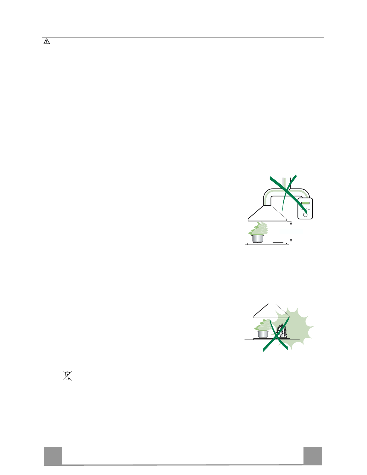
• The minimum safety distance between the cooker top and the extractor
hood is 650 mm (som e models can be installed at a lowe r height, please
refer to the paragraphs on working dimensions and installation).
• Check that the mains voltage corresponds to that indicated on the rating
plate fixed to the inside of the hood.
• For Class I appli ances, check that the domes tic power supply guarant ees
adequate earthing.
Connect the extractor to the exhaust flue through a pipe of minimum
diameter 120 mm. The route of the flue must be as short as possible.
• Do not connect the extractor hood to exhaust ducts carrying combustion
fumes (boilers, fireplaces, etc.).
• If the extractor is us ed i n c onjunction with no n-electrical a ppl i ances (e.g. gas
burning appl iances), a s ufficient degree of aeration mu st be guarant eed in
the room in orde r to preve nt the backflow of ex haust gas. The kit chen mus t
have an opening communicating directly with the open air in order to
guarantee the entry of clean air.
USE
• The extractor hood has been designed exclusively for domestic use to
eliminate kitchen smells.
• Never use the hood for purposes other than for which it has been designed.
• Never le ave hi gh na ke d fla me s un de r the hood wh en i t is in op er ati on .
• Adjust the flame in te nsi ty to di r ect i t onto the bottom o f t he pan only, maki ng
sure that it does not engulf the sides.
• Deep fat f ryers must be c ontinuously monit ored during us e: overheated oil
can burst into flames.
• Do not flambè under the range hood; risk of fire
• This appli ance is not inten ded for use by pers ons (including c hildren) with
reduced physi cal, sensory or m ental capabi lities, or lack o f experience an d
knowledge, unless they have been given supervision or instruction
concerning use of the appliance by a person responsible for their safety.
• Children should be supervised to ensure that they do not play with the
appliance.
MAINTENANCE
• Switch off or unplug t he a ppl iance from the mains supply before ca rr yi n g ou t
any maintenance work.
• Clean and/or replace the Filters after the specified time period (Fire hazard).
• Clean the hood using a damp cloth and a neutral liquid detergent.
The symbol on the product or on its packaging indicates that this product may not be treated
as household waste. Instead it shall be handed over to the applicable collection point for the
recycling of elec tr i cal and el ectronic eq uipment. By ensuring this product is di s p osed of c orrectly,
you will help prevent potential negative consequences for the environment and human health,
which could otherwise be caused by inappropriate waste handling of this product. For more
detailed information about recycling of this product, please contact your local city office, your
household waste disposal service or the shop where you purchased the product.
650 mm min.
Page 4
EN
4
4
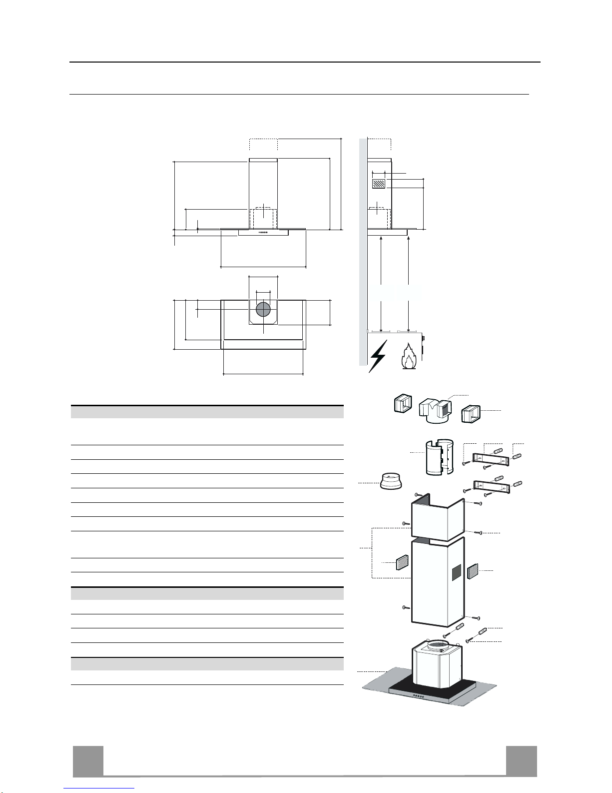
CHARACTERISTICS
Dimensions
Min.
650mm
Min.
650mm
520
420
46
8
598 / 698 / 898
530
108
259
150
740
740
945
90
135
433
260
300
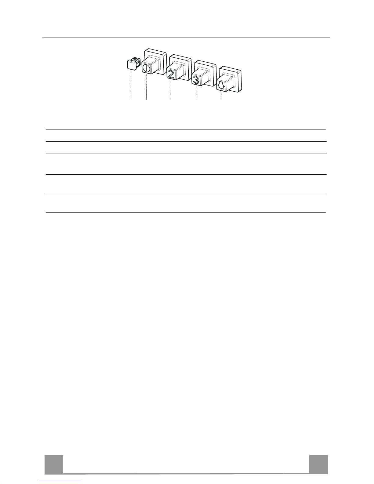
Components
Ref. Q.ty Product Components
1 1 Hood Body, complete with: Controls, Light, Blower,
Filters
2 1 Telescopic Chimney comprising:
2.1 1 Upper Section
2.2 1 Lower Section
8a 1 Right Air Outlet Grill
8b 1 Left Air Outlet Grill
9 1 Reducer Flange ø 150-120 mm
14 1 Hood Body Air Outlet Ext ension Piec e consisting of two
Half Shells
14.1 2 Air Outlet Conn ection Extension
15 1 Air Outlet Connecti on
Ref. Q.ty Installation Components
7.2.1 2 Upper Chimney Section Fixing Brackets
11 6 Wall Plugs
12a 6 Screws 4,2 x 44,4
12c 6 Screws 2,9 x 9,5
Q.ty Documentation
1 Instruction Manual
2.1
2.2
2
12c
12a
7.2.1 11
11
12a
1
8a
9
8b
14
14.1
15
Page 5
EN
5
5
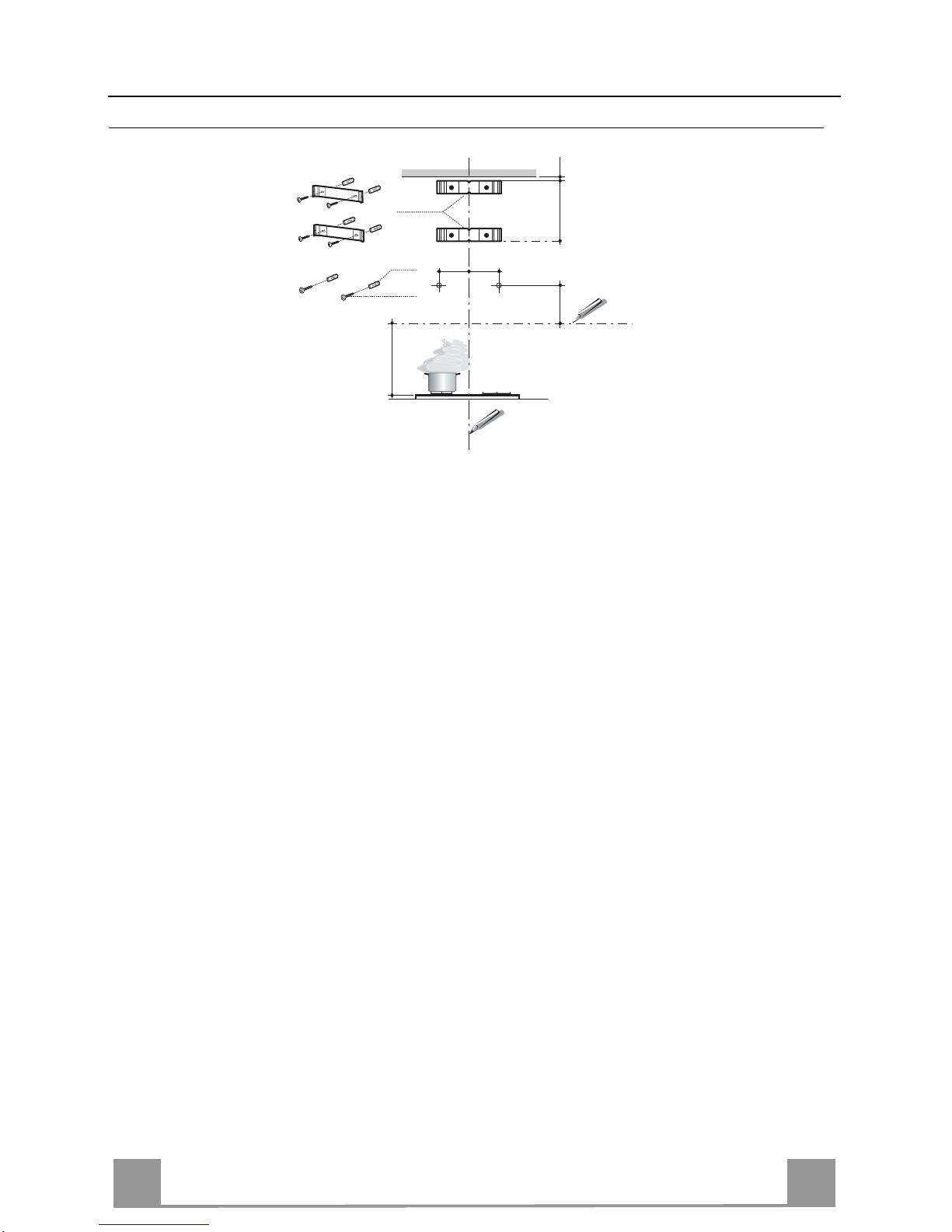
INSTALLATION
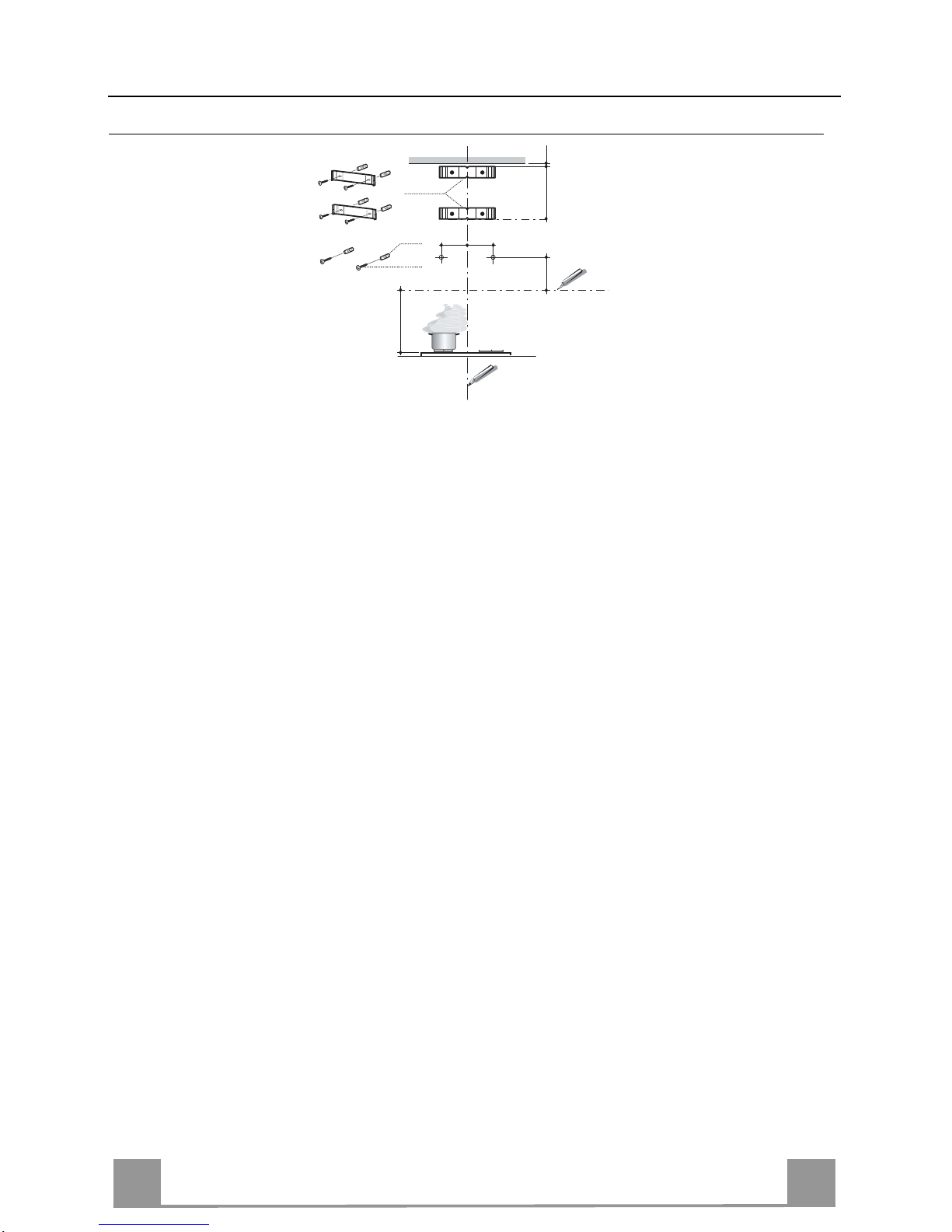
Wall drilling and bracket fixing
Wall marking:
• Draw a vertical line on the supporting wall up to the ceiling, or as high as practical, at the
centre of the area in which the hood will be installed.
• Draw a horizontal line at 650 mm above the hob. Place bracket 7.2.1 on the wall as shown
about 1-2 mm from the ceiling or upper limit aligning the centre (notch) with the vertical
reference line.
• Mark th e wall at the centres of the holes in the bracket.
• Place bracket 7.2.1 on the wall as shown at X mm below the first bracket (X = height of the
upper chimney section supplied), aligning the centre (notch) with the vertical line.
• Mark th e wall at the centres of the holes in the bracket.
• Mark a reference point as indi cated at 116 mm from the vertical reference lin e and 306 mm
above the horizontal reference line.
• Repeat this operation on the other side.
• Drill ø 8 mm holes at all the centre points marked.
• Insert the wall plugs 11 in the holes.
• Fix the brackets using th e 12a (4,2 x 44,4) screws supplied.
• Insert the two screws 12a (4,2 x 44,4) supplied in the hood body fixing holes, leaving a gap
of 5-6 mm between the wall and the head of the screw.
11
12a
306
X
116
1÷2
116
650 min.
7.2.1
Page 6
EN
6
6
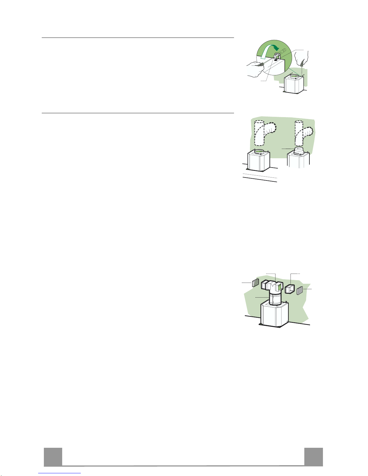
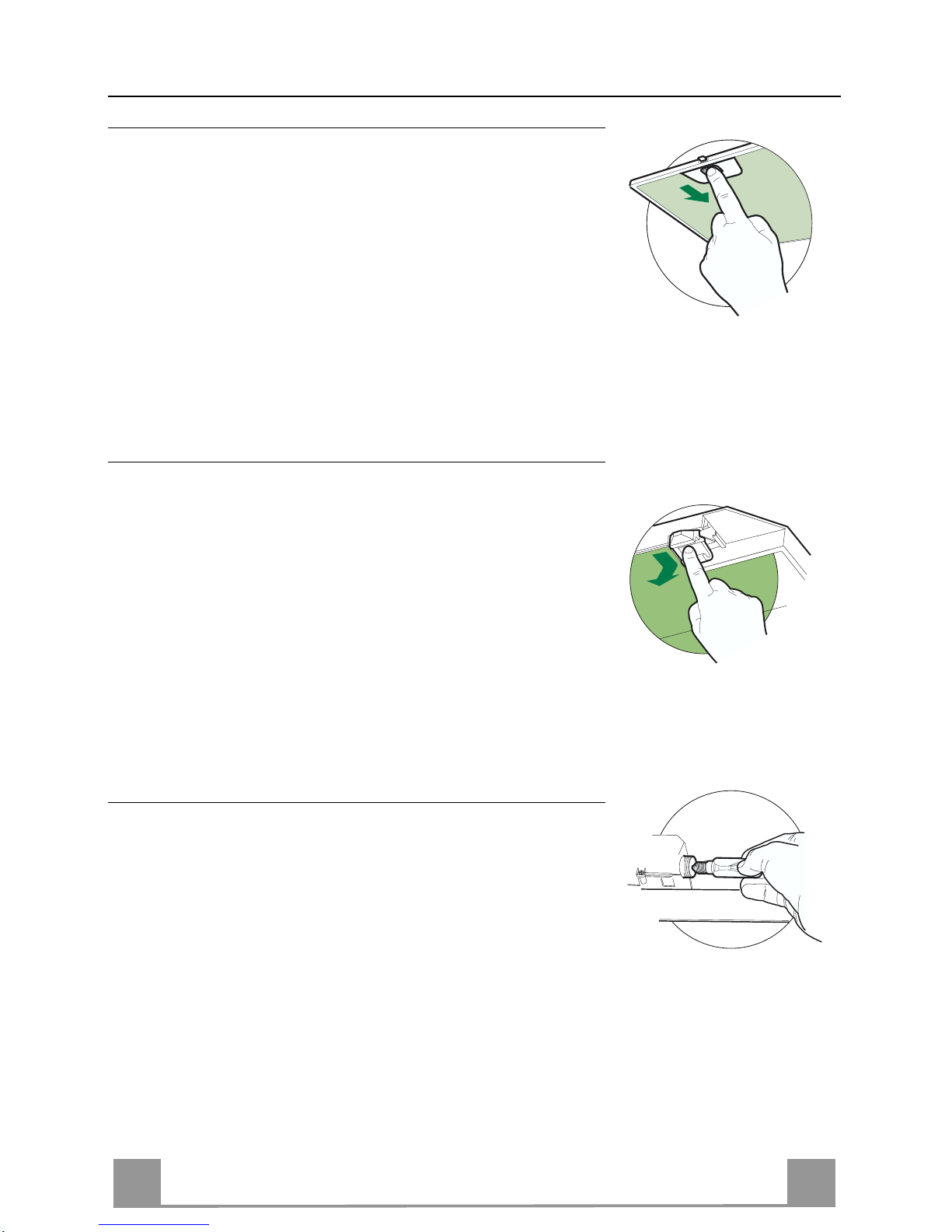
Mounting the hood body
• Before attaching the hood body, tighten the two screws Vr located on the hood body mounting points.
• Hook the hood body onto the screws 12a.
• Fully tighten support screws 12a.
• Adjust screws Vr to level the hood body.
12a
Vr
Connections
DUCTED VERSION AIR EXHAUST SYSTEM
When installing the ducted version, connect the hood to the
chimney using either a flexible or rigid pipe ø 150 or 120 mm,
the choice of which is left to the installer.
• To install a ø 120 mm air exhaust connection, insert the reducer flange 9 on the hood body outlet.
• Fix the pipe in position using sufficient pipe clamps (not supplied).
• Remove any activated charcoal fil t ers.
9
ø 120ø 150
RECIRCULATION VERSION AIR OUTLET
• Assemble the two halves of the hood body extension piece 14.
• Push fit the assembled hood body extensio n piece 14 onto the
air outlet.
• Push fit connection 15 onto the hoo d body extension p iece 14.
• Insert the conn ection exten sion pieces laterall y 14.1 in connection 15.
• M ake sure that the outlet of the extensio n pieces 14.1 is horizontally and vertically aligned with the chimney outlets. If this
is not the case, adjust the position by either reversing the connection exten sion pieces 14.1 or by cutting the hood body extension 14 along one of the thinner section channels denoting
the pre-fixed lengths, then reassemble as described previously.
• The air outlet directional grills 8a - 8b must be fitted after the
lower outlet duct has been installed.
• Ensure that the activated charcoal filters have been inserted.
14
14.115
8a
8b
Page 7
EN
7
7
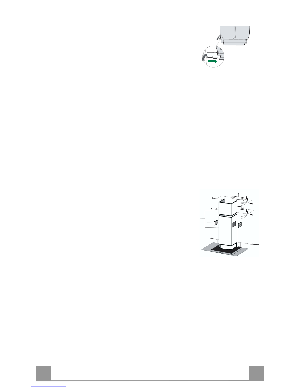
ELECTRICAL CONNECTION
• Connect the hood to the mains through a two-pole switch having a contact gap of at least 3 mm.
• Remove the grease filters (see paragraph Maintenance) being
sure that the co nnector of the feeding cable is correctly inserted
in the socket placed on the side of the fan.
Flue assembly
Upper exhaust flue
• Slightly widen the two sides of the upper flue and hook them
behind the brackets 7.2.1, making sure that they are well
seated.
• Secure the sides to the brackets using the 4 screws 12c (2,9 x
9,5) supplied.
Lower exhaust flue
• Slightly widen the two sides of the flue and hook them between the upper flue and the wall, making sure that they are
well seated.
• Fix the lower part laterally to the hood body using the 2 screws
12c (2,9 x 9,5) supplied.
• On the recirculation version, fit the directional grids 8a – 8b in
their housings making sure that the directional symbols are towards the top and front of the hood. Also make sure that they
are correctly inserted in the connection extension pieces 14.1.
12c
8a
2.1
2.2
2
8b
7.2.1
12c
Page 8
EN
8
8
USE
S
V1V1V1V1V1V1V1V1V1V1V1V1V1V1V1V1V1V1
V2
V3
L
L Light Switches the lighting system on and off.
S Led Motor running led.
V1 Motor Switches the extractor motor on and off at low speed. Used to provide a
contin-uos and silent air change in the presence of light cooking vapours.
V2 Speed Medium speed, suitable for most operating conditions given the optimum
treated air flox/noise level ratio.
V3 Intensive Maximum speed, used for eliminating the high est cooking vapour emission,
including long periods.
Page 9
EN
9
9
MAINTENANCE
Grease filters
CLEANING METAL SELF- SUPPORTING GREASE FILTERS
• The filters must be cleaned every 2 months of operation, or
more frequently for particularly heavy usage, and can be
washed in a dishwasher.
• Remove the filters one at a time by pushing them towards the
back of the group and pulling down at the same time.
• Wash the filters, taking care not to bend them. Allow them to
dry before refitting.
• When refitting the filters, make sure that the handle is visible
on the outside.
Activated charcoal filter (Recirculation version)
REPLACING THE ACTIVATED CHARCOAL FIL T ER
• The filter is not washable and cannot be regenerated, and must
be replaced approximately every 4 months of operation, or
more frequently for particularly heavy usage.
• Remove the metal grease filters
• Remove the saturated activated carbon filter by releasing the
fixing hooks
• Fit the new filter by hooking it into its seating
• Replace the metal greas e filters.
Lighting
LIGHT REPLACEMENT
40 W incandescent lig ht.
• Remove t he screw fixing the Lightin g support.
• Pull the Lighting support down.
• Extract the lamp and replace with another of the same type.
• Replace the lighting support in reverse order.
Page 10
IT 110
CONSIGLI E SUGGERIMENTI
Questo libretto di istruzioni per l'uso è previsto per più version
i dell' appare
c
chio.
É possibile che siano descritti singoli particolari della dotazione, che non
riguardano il Vost r o apparec c hio.
INSTALLAZIONE
• Il produttore declina qualsiasi responsabilità per danni dovuti ad installazione non
corretta o non c onfor me alle regole d ell’art e.
• La distanza minima di sicurezza tra il Piano di cottura e la Cappa deve essere di
650 mm, (alcuni modelli possono essere installati ad un’altezza inferiore, fare
riferimento ai par agraf i i ngombro e i nst all az ione) .
• Verificare che la tensione di rete corrisponda a quella riportata nella targhetta
posta all’interno della Cappa.
• Per Apparecchi in Classe I
a
accertarsi che l’impianto elettrico domestico
garantisca un c or ret to sc ar ico a t err a.
• Collegare la Cappa all’uscita dell’aria aspirata con tubazione di diametro pari o
superiore a 120 mm. Il percorso della tubazione deve essere il più breve
possibile.
• Non collegare la Cappa a condotti di scarico dei fumi prodotti da combustione
(caldaie, c aminet t i, ec c.) .
• Nel caso in cui nella stanza vengano utilizzati sia la Cappa che apparecchi non
azionati da energia elettrica (ad esempio apparecchi utilizzatori di gas), si deve
provvedere ad una aerazione sufficiente dell’ambiente. Se la cucina ne fosse
sprovvista, praticare un’apertura che comunichi con l’esterno, per garantire il
richiamo d’ari a puli t a.
USO
• La Cappa è stata progettata esclusivamente per uso domestico, per abbattere gli
odori della cuc ina.
• Non fare mai uso impropri o dell a Cappa.
• Non lasciare fiamme liber e a for t e int ensi tà sot to l a Cappa in f unz ione.
• Regolare sempre le fiamme in modo da evitare una evidente fuoriuscita laterale
delle stess e ri spet t o al fondo del le p ent ole.
• Controllare le friggi tr ici dur ante l ’us o: l’ oli o surrisc al dato pot rebb e i nfi ammars i .
• Non preparare alimenti fl ambè s ott o la c appa da c uci na; peri col o d'inc en dio.
• Questo apparecch io non de ve essere utilizza to da pe rsone (ba mbini inclu si) con
ridotte capacità psichiche, sensoriali o mentali, oppure da persone senza
esperienza e conoscenza, a meno che non siano controllati o istruiti all’uso
dell’apparecchio da per son e r esponsabili della loro sicurezza.
• I bambini devono essere supervisionati per assicurarsi che non giochino con
l’apparecchi o.
MANUTENZIONE
• Prima di procedere a qualsiasi operazione di manutenzione, disinserire la Cappa
togliendo la spina elettrica o spegnendo l’interruttore generale.
• Effettuare una scrupolosa e tempestiva manutenzione dei Filtri secondo gli
intervall i cons igl i ati (R isc hio di incendi o).
• Per la pulizia d e lle su perfici d e lla C a pp a è sufficie n te u tiliz za re u n pa nn o umido e
detersivo l iqui do neutr o.
Il simbolo sul prodotto o sulla confezione indica che il prodotto non deve essere considerato
come un no r m ale rifiuto domes t i c o , m a deve ess ere portato nel punto di raccolta a ppropriat o per
il riciclaggio di apparecchiature elettriche ed elettroniche. Provvedendo a smaltire questo
prodotto in modo appropriato, si contribuisce a evitare potenziali conseguenze negative per
l’ambiente e per la salute, che potrebbero derivare da uno smaltimento inadeguato del prodotto.
Per infor maz ioni più d ett agli ate s ul ric icla ggio di q uest o pro dott o, co ntatt are l ’uffi cio c omu nale , il
servizio locale di sma ltimen to rifiu ti o il negozi o in cui è stato acquista to il prodo tto .
650 mm min.
Page 11

IT 111
CARATTERISTICHE
Ingombro
Min.
650mm
Min.
650mm
520
420
46
8
598 / 698 / 898
530
108
259
150
740
740
945
90
135
433
260
300
Componenti
Rif. Q.tà Componenti di Prodotto
1 1 Corpo Cappa completo di: Comandi, Luce, Gruppo
Ventilatore, Filtri
2 1 Camin o Telescopico formato da:
2.1 1 Camino Superiore
2.2 1 Camino Inferiore
8a 1 Griglia Direzionata DX Uscita Aria
8b 1 Griglia Direzionata SX Uscita Aria
9 1 Flangia di Riduzione ø 150-120 mm
14 1 Prolunga Uscita Aria Corpo Cappa formata da 2 Semi-
gusci
14.1 2 Prolunga Raccordo Uscita Ari a
15 1 Raccordo Uscita Aria
Rif. Q.tà Componenti di Installazione
7.2.1 2 Staff e Fis saggio Camino Superiore
11 6 Tasselli
12a 6 Viti 4,2 x 44,4
12c 6 Viti 2,9 x 9,5
Q.tà Documentazione
1 Libretto Istruzioni
2.1
2.2
2
12c
12a
7.2.1 11
11
12a
1
8a
9
8b
14
14.1
15
Page 12
IT 112
INSTALLAZIONE
Foratura Parete e Fissaggio Staffe
Tracciare sulla Parete:
• una linea Verticale fino al soffitto o al limite superiore, al centro della zona prevista per il
montaggio della Cappa;
• una linea Orizzontale a: 65 0 mm min . sopra il Piano di Cottura.
• Appoggiare come indicato la Staffa 7.2.1 a 1-2 mm dal soffitto o dal limite superiore,
allineando il suo centro (intagli) sulla linea Verticale di riferimento.
• Segnare i centri dei Fori della Staffa.
• Appoggiare co me indicato la Staffa 7.2.1 a X mm sotto l a prima staffa (X = alt ezza Camino
Superiore in dotazione), allineando il suo centro (intagli) sulla linea Verticale di riferimento.
• Segnare i centri dei Fori della Staffa.
• Segnare come indicato, un punto di riferimento a 116 mm dalla linea Verticale di
riferimento, e 306 mm sopra la linea Orizzontale di riferimento.
• Ripetere questa operazione dalla parte opposta.
• Forare ø 8 mm i punti segnati.
• Inserire i tasselli 11 nei fori.
• Fissare le Staffe, utilizzando le Viti 12a (4,2 x 44,4 ) in dotazione.
• Avvitare 2 Viti 12a (4,2 x 44,4) in dotazione nei fori per il fissaggio del corpo Cappa,
lasciando uno spazio di 5-6 mm fra la parete e la testa della vite.
11
12a
306
X
116
1÷2
116
650 min.
7.2.1
Page 13

IT 113
Montaggio Corpo Cappa
• Prima di agganciare il Corpo Cappa, serrare le 2 Viti Vr situate
sui punti di aggancio del Corpo Cappa.
• Agganciare il Corpo Cappa alle Viti 12a.
• Serrare definitivamente le Viti 12a di supporto.
• Agire sulle Viti Vr per livellare il Corpo Cappa.
12a
Vr
Connessioni
USCITA ARIA VERSIONE ASPIRANTE
Per installazione in Versione Aspirante collegare la Cappa alla
tubazione di uscita per mezzo di un tubo rigido o flessibile di
ø150 o 120 mm, la cui scelta è lasciata all'installatore.
• Per collegamento con tubo ø120 mm, inserire la Flangia di riduzione 9 sull’Uscita del Corpo Cappa.
• Fissare il tubo con adeguate fascette stringitubo. Il materiale
occorrente non è in dotazione.
• Togliere eventuali Filtri Antiodore al Carbone attivo.
9
ø 120ø 150
USCITA ARIA VERSIONE FILTRANTE
• Assemblare i Semigusci della Prolunga Corpo Cappa 14.
• Inser ire a pressione la P rolunga Corpo Capp a 14 così ottenuta,
sull’Uscita Aria.
• Inserire a pressio ne il Raccordo 15 sulla Prolunga Corpo Cappa 14.
• In serire lateralmente le P rolunghe Racco rdo 14.1 sul Raccordo
15.
• Assicurarsi che l’uscita delle Prolunghe Raccordo 14.1 risulti
in corrispondenza delle bocchette del Camino sia in orizzontale
che in verticale. Se co sì non fosse, aggiustare la posizione invertendo le Prolunghe Raccordo 14.1 o tagliando la Prolunga
Corpo Cappa 14 in co rrispondenza di un a delle lun ghezze prestabilite dalle scanalature di minor spessore e rimontare i particolari come prima descritto.
• Le Griglie direzionate Uscita Aria 8a - 8b devono essere mon-
tate dopo l’installazione del Camino Inferiore 2.2.
• Assicurarsi della presenza del Filtro Antiodore al Carbone attivo.
14
14.115
8a
8b
Page 14

IT 114
CONNESSIONE ELETTRICA
• Collegare la Cappa all’Alimentazione di Rete interponendo un
Interruttore bipolare con apertura dei contatti di almeno 3 mm.
• Rimuovere i Filtri antigrasso (vedi par. “Manutenzione”) e assicurarsi che il connettore del Cavo di alimentazione sia correttamente inserito nella presa dell’Aspiratore
Montaggio Camino
Camino superiore
• Allargare leggermente le due falde laterali, agganciarle dietro
le Staffe 7.2.1 e richiuderle fino a battuta.
• Fissare lateralmente alle Staffe con 4 Viti 12c (2,9 x 9,5) in
dotazione.
Camino inferiore
• Allargare leggermente le due falde laterali del Camino, agganciarle tra il Camino superiore e la parete e richiuderle fino a
battuta.
• Fissare lateralmente la parte inferiore al Corpo Cappa, con 2
Viti 12c (2,9 x 9, 5) in dotazi one.
• Per la Versione Filtrante applicare le Griglie direzionate 8a 8b nelle apposite sedi, in modo che i simboli direzionali risultino orientati verso l’alto e il fronte della Cappa. Assicurarsi
inoltre che risultino inserite correttamente nelle Prolunghe
Raccordo 14.1.
12c
8a
2.1
2.2
2
8b
7.2.1
12c
Page 15

IT 115
USO
S
V1V1V1V1V1V1V1V1V1V1V1V1V1V1V1V1V1V1
V2
V3
L
L Luci Accende e spegne l’Impianto di Illuminazione.
S Led Led accension e Motore.
V1 M otore Accende e spegne il motore Aspirazione a velocità minima, adatta ad un
ricambio d’aria continuo particolarmente silenzioso, in presenza di pochi
vapori di cottura.
V2 V elocità Velocità media, adatta alla maggior parte delle condizioni d’uso, dato
l’ottimo rapporto tra portata d’aria trattata e livello sonoro.
V3 V elocità Velocità massima, adatta a fronteggiare le massime emissioni di vapore di
cottura, anche per tempi prolungati.
Page 16

IT 116
MANUTENZIONE
Filtri antigrasso
PULIZIA FILTRI ANTIGRASSO METALLICI AUTOPORTAN TI
• Sono lavabili anche in lavastoviglie, e necessitano di essere
lavati ogni 2 mesi circa di utilizzo o più frequentemente, per un
uso particolarmente intenso.
• Togliere i Filtri uno alla volta, spingendoli verso la parte posteriore del gruppo e tirando contempo raneamente verso il basso.
• Lavare i Filtri evitando di piegarli, e lasciarli asciugare prima
di rimontarli.
• Rimontarli facendo attenzione a mantenere la maniglia verso la
parte visibile esterna.
Filtro antiodore (Versione Filtrante)
SOSTITUZIONE FILTRO ANTIODORE AL CARBONE ATTIVO
• Non è lavabile e non è rigenerabile, va sostituito almeno ogni 4
mesi o più frequentemente, per un uso particolarmente intenso.
• Togliere i Filtri antigrasso metallici.
• Rimuovere il Filtro antiodore al Carbone attivo saturo, agendo
sugli appositi agganci.
• Montare il nuovo Filtro agganciandolo nella sua sede.
• Rimontare i Filtri antigrasso metallici.
Illuminazione
SOSTITUZIONE LAMPADE
Lampade a incandescenza da 40 W.
• Togliere la vite che fissa la plafoniera.
• Tirare la plafoniera verso il basso.
• Svitare la lampada e sostituirla con una nuova di uguali caratteristiche.
• Rimontare la plafoniera in sequenza inversa.
Page 17

FR
117
CONSEILS ET SUGGESTIONS
La présente notice d'emploi vaut pour plusieurs versions de l'appareil. Elle peut
contenir des descriptions d'acc ess oi res ne fi gurant pas dans votre ap parei l.
INSTALLATION
• Le fabricant décline toute responsabilité en cas de dommage dû à un e in sta llatio n n on
correcte ou non conforme aux règl es d e l’ art.
• La distance minimale de sécurité entre le plan de cuisson et la hotte doit être de 650
mm au moins (certains modèles peuvent être installés à une hauteur inférieure : se
reporter aux paragraphe s « E ncombrem ent » et « Inst allat ion »).
• Vérifier que la tension du secteur correspond à la valeur qui figure sur la plaquette
apposée à l’intérieur de la hotte.
• Pour les Appareils appartenant à la Ière Classe, veiller à ce que la mise à la terre de
l’installation électrique domestique ait été effectuée conformément aux normes en
vigueur.
• Connecter la hotte à la sortie d’air aspiré à l’aide d’une t uyauterie d’un diamètre égal ou
supérieur à 120 mm. Le parcours de l a tuyaut eri e doit être le plus court possibl e.
• Ne pas connecter la hotte à des conduites d’évacuation de fumées issues d’une
combustion tel que (C haudièr e, chemi née, et c…).
• Si vous utilisez des appareils qui ne fonctionnent pas à l’électricité dans la pi èce ou est
installée la hotte (par exemple: des appareils fonctionnant au gaz), vous devez prévoir
une aération suffisante du milieu. Si la cuisine en est dépourvue, pratiquez une
ouverture qui communique av ec l ’ext érieur pour garant ir l’i nfiltr ation de l’ai r pur .
UTILISATION
• La hotte a été conçue exclusivement pour l’usage domestique, dans le but d’éliminer
les odeurs de la cuisine.
• Ne jamais utiliser abusivement la hot te.
• Ne pas laisser les flammes l ibres à fort e intensit é quand la hot te est en service.
• Toujours régler les flammes de manière à éviter toute sortie latérale de ces dernières
par rapport au fond des marmit es.
• Contrôler les frit euses lor s de l’ utili sation car l’huile sur chauff ée pourrai t s’ enfl ammer.
• Ne pas préparer d’ali ments f lambés sous l a hott e de cuisi ne : risque d’ incendi e
• Cet appareil ne doit pas être utilisé par des personnes (y compris les enfants) ayant
des capacités psychiques, sensorielles ou mentales réduites, ni par des personnes
n’ayant pas l’expérience et la connaissance de ce type d’appareil s, à moins d'être sous
le contrôle et la formati on de personn es respo nsables de l eur sécuri té.
• Les enfants doivent être surveillés pour s'assurer qu'ils ne jouent pas avec l'apparei l.
ENTRETIEN
• Avant de procéder à toute opér ation d’entretien, r etirer la hotte en retirant la fiche ou en
actionnant l’interrupteur général.
• Effectuer un entretien scrupuleux et en temps dû des Filtres, à la cadence conseillée
(Risque d’incendie) .
• Pour le nettoyage des surfaces de la hotte, il suffit d’utiliser un chiffon humide et
détersif liquide neut re.
Le symbole sur le produit ou son emballage indique que ce produit ne peut être traité comme
déchet ménager. Il doit plutôt être remis au point de ramassage concerné, se chargeant du
recyclage du matériel électrique et électronique. En vous assurant que ce produit est éliminé
correctement, vous favorisez la prévention des conséquences négatives pour l’environnement et la
santé humaine qui, sinon, seraient le résultat d’un traitement inapproprié des déchets de ce produit.
Pour obtenir plus de déta ils sur le recyclage de ce pr oduit, veuillez pre ndre contact avec le bur eau
municipal de votre région, votre service d’élimination des déchets ménagers ou le magasin où vous
avez acheté le produit.
650 mm min.
Page 18

FR
118
CARACTERISTIQUES
Encombrement
Min.
650mm
Min.
650mm
520
420
46
8
598 / 698 / 898
530
108
259
150
740
740
945
90
135
433
260
300
Composants
Réf. Q.té Composants de Produit
1 1 Corps Hotte éq uipé de : Command es, Lumiè re, Groupe
Ventilateur, Filtres
2 1 Cheminée T élescopique formée de:
2.1 1 Cheminée Supérieure
2.2 1 Cheminé e Inférieure
8a 1 Grille en Direction Droite Sortie Air
8b 1 Grille en Direction Gauche Sortie Air
9 1 Flasque de Réduction ø 150- 12 0 mm
14 1 Rallonge Sortie Air Corps Hotte formée de 2 Semi-
Coques
14.1 1 Rallonge Raccord Sortie Air
15 1 Raccord Sortie Air
Réf. Q.té Composants pour l’installation
7.2.1 2 Brides Fixation Cheminée Supérieure
11 6 Chevilles
12a 6 Vis 4,2 x 44,4
12c 6 Vis 2,9 x 6,5
Q.té Documentation
1 Manuel d’instructions
2.1
2.2
2
12c
12a
7.2.1 11
11
12a
1
8a
9
8b
14
14.1
15
Page 19

FR
119
INSTALLATION
Perçage Paroi et Fixation Brides
Tracer sur la paroi:
• une ligne verticale allant jusqu’au plafond ou à la limite supérieure, au centre de la zone
prévue pour le montage de la hotte;
• une ligne horizontale à 650 mm min. au-dessus du plan de cuisson.
• Poser comme indiqué une bride 7.2.1 sur la paroi à 1-2 mm du plafond ou de la limite
supérieure, en alignant son centre (découpes) sur la l i gne verticale de repère.
• Marquer les centres des trous rainurés de la bride.
• Poser comme indiqué la bride 7.2.1 à X mm sous la première brid e (X = hauteur ch eminée
supérieure fournie), en alignant son centr e (découpes) sur la ligne verticale d e repère.
• Marquer les centres des trous rainurés de la bride.
• Marquer comme indiqué, un point de référence à 116 mm de la ligne verticale de repère, et
306 mm au-dessus de la ligne horizontale de repère.
• Répéter cette opération sur le côté opposé.
• Percer de ø 8 mm tous les points marqués.
• Insérer les chevilles 11 dans les trous.
• Fixer les brides en utilisant les vis 12a (4,2 x 44,4) fournies.
• Visser les 2 vis 12a (4,2 x 44,4) fournies dans les trous de fixation du corps hotte, en laissant
un espace de 5-6 mm entre le mur et la tête de la vis.
11
12a
306
X
116
1÷2
116
650 min.
7.2.1
Page 20

FR
220
Montage Corps Hotte
• Avant d’accrocher le co rps hotte, serrer les deux vis Vr situées
sur les points d’accro chage du corps hotte.
• Accrocher le corps hotte aux vis 12a prévues à cet effet.
• Serrer définitivement les vis 12a de support.
• Agir sur les vis Vr pour niveler le corps hotte.
12a
Vr
Branchements
SORTIE AIR VERSION ASPIRANTE
En cas d’install ation en version aspirante, brancher la ho tte à la
tuyauterie de sortie via un tube rigide ou flexible de ø 150 ou 120
mm, au choix de l’installateur.
• En cas de branchement avec un tube de ø120 mm, insérer le
flasque de réduction 9 sur la sortie du corps de la hotte.
• Fixer le tube par des colliers appropriés. Le matériau nécessaire n’est pas fourni.
• Retirer les éventuels filtres anti-odeur au charbon actif.
9
ø 120ø 150
SORTIE AIR VERSION FILTRANTE
• Assembler les semi-coques de la rallonge corps hotte 14.
• In sérer sous p ression la rallonge corp s hotte 14 ainsi obtenue, à
la sortie air.
• In sérer sous pression le raccord 15 sur la rallonge corps hotte
14.
• Insérer latéralement les rallonges raccord 14.1 sur le raccord
15.
• S’assurer qu e la sortie des rallonges r accord 14.1 se trouve au
niveau des bouches de la cheminée aussi bien en horizontal
qu’en vertical.
• Si tel n’est pas le cas, ajuster la position en inversant les rallonges raccord 14.1 ou en coupant la rallonge corps hotte 14 au
niveau d’une des longueurs prédéfinies par les rainures moins
épaisses et remonter les p ièces comme décrit au préalable.
• Les grilles 8a - 8b en direction sortie air do ivent être montées
après l’installation de la cheminée inférieure.
• S’assurer de la présence des filtres anti-odeur au charbon actif.
14
14.115
8a
8b
Page 21

FR
221
BRANCHEMENT ELECTRIQUE
• Branch er la hotte sur le secteur en interposant un interrupteur
bipolaire avec ouverture des contacts d’au moins 3 mm.
• Enlever les filtres à graisse (voir § "Entretien") et s'assurer que
le connecteur du câb le d 'alimentati on so it bi en bran ché dan s la
prise du diffuseur.
Montage Cheminée
Cheminée supérieure
• Elargir légèrement les deux bords latériaux, et les accrocher
derrières les brides 7.2.1 ; refermer jusqu’à la butée.
• Fixer latéralement aux brides à l’aide des 4 vis 12c (2,9 x 9,5)
fournies.
Cheminée inférieure
• Elargir légèrement les deux bords latériaux de la Cheminée et
les accrocher entre la Che minée supérieure et la p aroi; refermer
jusqu’à la butée.
• Fixer latéralement la partie inférieure au corps hotte, à l’aide
des deux 2 vis 12c (2,9 x 9,5) fournies.
• Pour la version filtrante, appliquer les grilles en direction 8a – 8b
dans les logements appropriés, pour que les symboles de direction soient orientés vers le haut et la partie avant de la hotte.
S’assurer également qu’elles sont bien insérées dans les rallonges raccord 14.1.
12c
8a
2.1
2.2
2
8b
7.2.1
12c
Page 22

FR
222
UTILISATION
S
V1V1V1V1V1V1V1V1V1V1V1V1V1V1V1V1V1V1
V2
V3
L
L Lumières Allume et éteint l’in st allation de l’éclairage.
S Del Del allumage Moteur.
V1 Moteur Met en marche et à l’arrêt le moteur aspiration à vitesse minimale, pour un
rechange d’air permantent particulièrement silencieux en cas de faibles vapeurs de cuisson.
V2 Vitesse Vitesse moyenne pour la plupart des conditions d’utilisation, étant donné le
rapport optimal entre débit d’air traité et niveau sonore.
V3 Vitesse Vitesse maximum, pour faire face aux émissions maximum de vapeur de
cuisson, même pendant des temps prolongés.
Page 23

FR
223
ENTRETIEN
Filtres anti-graisse
NETTOYA GE FILTRES AN TI-GR AISSE M ETALLIQ UES AU TOPORTE URS
• Lavables au lave-vaisselle, ils doivent être lavés environ tous
les 2 mois d’emploi ou plus fréquemment en cas d’emploi particulièrement intense.
• Retirer les filtres l’un aprés l’autre, en les poussant vers la partie arrière du groupe et en tirant simultanément vers le bas.
• Laver les filtres en évitant de les plier et les laisser sécher avant
de les remonter.
• Remonter les filtres en veillant à ce que la poignée reste vers la
partie visible externe
Filtre anti-odeur (Version filtrante)
REMPLACEMENT FILTRE AU CHARBON ACTIF
• Ni lavable, ni régénérable, le remplacer au moins tous les 4
mois d’emploi ou plus fréquemment en cas d’emploi particulièrement intense.
• Retirer les filtres anti-graisse métalliques.
• Retirer le filtre anti-odeur au charbon actif colmaté, en agissant
sur les crochets prévu s à cet effet.
• Monter le nouveau filtre anti-odeur au charbon actif.
• Remonter les filtres anti-graisse métalliques.
Eclairage
REMPLACEMENT LAMPES
Lampe à incandesce nce de 40 W.
• Retirer la vis qui fixe le Support éclairage.
• Tirer le Support vers le bas.
• Extraire la Lampe du Support.
• Remplacer par u ne nouvelle lampe possédant les mêmes caractéristiques.
• Remonter le Support éclairage.
Page 24

DE
224
EMPFEHLUNGEN UND HINWEISE
Diese Gebrauchsanleitung gilt für mehrere Geräte-Ausführungen. Es ist möglich, dass
einzelne Ausstattungsmerkmale beschrieben sind, die nicht auf Ihr Gerät zutreffen.
MONTAGE
• Der Hersteller haftet nicht für Schäden, die auf eine fehlerhafte und unsachgemäße
Montage zurückzuführen sind.
• Der minimale Sicherheitsabstand zwischen Kochmulde und Haube muss 650 mm
betragen (einige Modelle können an einer geringeren Höhe installiert werden, beziehen
Sie sich dazu auf den Absatz Raumbedarf und Installation).
• Prüfen, ob die Netzspannung mit dem Wert auf dem im Haubeninneren
angebrachten Schil d übereinsti mmt.
• Bei Geräten der Klasse I ist sicherzustellen, dass die elektrische A nlage des Wohnhauses
über eine vorschriftsmäßige Erdung verfügt.
• Das Anschlussrohr der Haube zur Luftaustrittsöffnung muss einen Durchmesser von 120
mm oder darüber aufweisen. Der Rohrverlauf muss so kurz wie möglich sein.
• Die Haube darf an keine Entlüftungsschächte angeschlossen werden, in die
Verbrennungsgase (Heizkessel, Kamine usw.) geleitet wer den.
• Werden im Raum außer der Dunstabzugshaube andere, nicht elektrisch betriebene (z.B.
gasbetriebene) Geräte verwendet, muss für eine ausreichende Belüftung gesorgt werden.
Sollte die Küche diesbezüglich nicht entsprechen, ist an einer Aussenwand eine Öffnung
anzubringen, die Frischluftzufuhr gewährleist et.
BEDIENUNG
• Die Dunstabzugshaube ist ausschließlich zum Einsatz im privaten Haushalt und zur
Beseitigung von Küchengerüchen vorgesehen.
• Unsachgemäßer Einsatz der Haube ist zu unterlassen.
• Große Flammen bei eingeschalteter Haube niemals unbedeckt lassen.
Achtung! Große Flamme n bei ei ngesc halt ete r Haube niema ls unbedeck t lasse n.
• Die Intensivität der Flamme ist so zu regulieren, dass sie den Topfboden nicht überragt.
Achtung! Frittiergeräte müssen während des Gebrauchs stets beaufsichtigt
werden: Überhitztes Öl kann si ch entzünden.
• Frittiergeräte müssen während des Gebrauchs stets beaufsichtigt werden: überhitztes Öl
kann sich entzünden.
• Keine flambierten Speisen unter der A bzugshaube zuber eit en: Brandgef ahr.
• Dieses Gerät darf nicht von Personen, auch Kindern, mit verminderten psychischen,
sensorischen und geistigern Fähigkeiten, oder von Personen ohne Erfahrung und
Kenntnisse benutzt werden, sofern sie nicht von für ihre Sicherheit verantwortlichen
Personen beaufsichtigt und beim Gebrauch des Geräts angeleitet wer den.
• Kinder dürfen sich nicht unbeaufsichtigt in der Nähe des Geräts aufhalten und auf keinen
Fall mit dem Gerät spielen.
WARTUNG
• Bevor Wartungsarbeiten durchgeführt werden, muss die Stromzufuhr zur Haube
unterbrochen werden, inde m d er Stecker gezogen oder der Hauptschalter abgescha ltet wird.
• Bei der Filterwartung müssen die vom Hersteller empfohlenen Zeiträume zum Austauschen
der Filte r genauestens eingehalten werden.
• Zur Reinigung der Haubenflächen Wir empfehlen ein feuchtes Tuch und ein mildes
Flüssigreinigungsmittel.
• Bitte keine Reinigungsmittel mit Scheuermittel verwenden. Die Oberfläche wird damit
verkratzt.
Das Symbol auf dem Produkt oder seiner Verpackung weis t darauf hin, dass dieses Produkt nicht als
normaler Haushaltsabfall zu behandeln ist, sondern an einem Sammelpunkt für das Recycling von
elektrischen und elektronischen Geräten abgegeben werden muss. Durch Ihren Beitrag zum korrekten
Entsorgen dieses Produkts schützen Sie die Umwelt und die Gesundheit Ihrer Mitmenschen. Umwelt und
Gesundheit werden durch falsches Entsorgen gefährdet. Weitere Informationen über das Recycling dieses
Produkts erhalten Sie von Ihrem Rathaus, Ihrer Müllabfuhr oder dem Geschäft, in dem Sie das Produkt
gekauft haben.
650 mm min.
Page 25

DE
225
CHARAKTERISTIKEN
Platzbedarf
Min.
650mm
Min.
650mm
520
420
46
8
598 / 698 / 898
530
108
259
150
740
740
945
90
135
433
260
300
Komponenten
Pos. St. Produktkompone nten
1 1 Haubenkörper mit Schaltern, Beleuchtung, Gebläse-
gruppe, Filter
2 1 Teleskopkamin bestehend aus:
2.1 1 oberer Kaminteil
2.2 1 unterer Kaminteil
8a 1 Luftleitgitter Luftaustritt rechts
8b 1 Luftleitgitter Luftaustritt links
9 1 Reduzierfla nsch ø 150-1 20 mm
14 1 Verlängerungsstück f. Luftaustritt Haubenkörper, be-
stehend aus 2 Rohr häl ft e n
14.1 1 Verlängerung Luftaustritt-Anschlussstück
15 1 Luftaustritt-Anschlussstück
Pos. St. Montagekomponenten
7.2.1 2 Befestigungsbügel oberer Kaminteil
11 6 Dübel
12a 6 Schrauben 4,2 x 44,4
12c 6 Schrauben 2,9 x 6, 5
St. Dokumentation
1 Bedienungsanleitung
2.1
2.2
2
12c
12a
7.2.1 11
11
12a
1
8a
9
8b
14
14.1
15
Page 26

DE
226
MONTAGE
Bohren der Befestigungslöcher und Fixieren der Befestigungsbügel
Achtung: Bitte beachten Sie bei der Montage das Gewicht der kompletten Haube. Die Tragfähigkeit der
Decke oder alternativ der Trägerplatte für diese Zugbelastung muss vor der Montage geprüft und
gegebenenfalls durch die Anbringung von geeigneten Befestigungs- oder Stabilisierungselementen
hergestellt werden. Kann eine hinreichende Tragfähigkeit nicht sichergestellt werden, ist von einer
Montage abzu seh en.
Nachstehende Lin ien an die Wand zeichnen:
• eine vertikale Linie bis zur Decke oder oberen Begrenzung, und zwar in der Mitte des
Bereiches, in dem die Haube montiert werden soll;
• eine horizontale Linie mit einem minimalen Abstand von 650 mm zur Kochfläche.
• Einen Bügel 7.2.1 zirka 1-2 mm unter der Decke oder oberen Begrenzung an die Wand
legen und seinen Mittelpunkt (Einschnitte) auf die vertikale Bezugslinie ausrichten.
• Die Mitte der beiden Bügellöcher an der Wand markieren.
• Den zweiten Bügel 7.2.1 an die Wand legen, wobei ein Abstand X mm vom oberen Bügel
einzuhalten ist (X = Höhe des jeweiligen oberen Kaminteils); den Mittelpunkt (Einschnitte)
auf die vertikale Bezugsl inie ausrichten.
• Die Mitte der Bügellöcher an der Wand markieren.
• Wie beschrieben einen Bezugspunkt 116 mm von der vertikalen Bezugslinie und 306 mm
oberhalb der horizontalen Bezugslinie kennzeichnen.
• Gleichermaßen an der gegenüberliegenden Seite vorgehen.
• Mit einem Bohrer ø 8 mm die markierten Punkte bohren.
• Die Dübel 11 in die Bohrungen einfügen.
• Die Bügel mit den mitgelieferten Schrauben 12a (4,2 x 44,4) fixieren.
• 2 der mitgelieferten Schrauben 12a (4,2 x 44,4) bei den Befestigungslöchern des
Haubenkörpers einschrauben, wobei zwischen Wand und Schraubenkopf ein Freiraum von
5-6 mm zu belassen ist.
11
12a
306
X
116
1÷2
116
650 min.
7.2.1
Page 27

DE
227
Montage des Haubenkörpers
• Bevor der Haubenkörper eingehakt wird, die 2 Schrauben Vr
bei den Haubenkörper-Anhakpunkten festziehen.
• Den Haubenkörper bei den Sc hraube n 12a einhängen.
• Die Halteschrauben 12a definitiv festziehen.
• Den Haubenkörper mit Hilfe der Schrauben Vr ausrichten.
12a
Vr
Anschluss der Abluftversion
Bei Abluftbetrieb kann die Haube vom Installateur wahlweise
mittels Rohr oder Schlauch (ø 150 oder 120 mm) an die Außenrohrleitung angeschlossen werden.
• Bei Verwendung eines Anschlussrohres ø 120 den Reduzierflansch 9 am Haubenaustritt anbringen.
• Das Rohr mit geeigneten Rohrschellen fixieren. Das hierzu
erforderliche Material wird nicht mitgeliefert.
• Eventuell vorhandene Aktivkohlefilter entnehmen.
Achtung! Alle Q uerschnittänderungen oder Richt ungsän-
derunge n des A bluftka nals r eduzier en die L eistu ng der H aube.
9
ø 120ø 150
ANSCHLUSS IN UMLUFTVERSION
• Die beiden Rohrhälften des Verlängerungsstücks 14 zusammenbauen.
• Das auf diese Weise erzielte Verlängerungsstück 14 beim
Luftaustritt eindrücken.
• Den Anschluss 15 beim Verläng e r ung s s tüc k 14 eindrücken.
• Die Verl ängeru ngen 14.1 beim Anschluss 15 seitlich einfügen.
• Überprüfen, ob die Verlän gerungen 14.1 mit den entsprechenden Kaminstutzen sowohl horizontal wie auch vertikal übereinstimmen.
• Sollte dies nicht der Fall sein, müssen die Verlängerungen 14.1
miteinander vertauscht oder muss das HaubenkörperAnschlussstück 14 bei einer der vorgegebenen Längen (schmale Nut) abgeschnitten und wie zuvor beschrieben wieder zusammengebaut werden.
• Die Luftleitgitter werden nach der Installation des unteren Kaminteils montiert.
• Kontrollieren, ob der Aktivkohle-Geruchsfilter vorhanden ist.
14
14.115
8a
8b
Page 28

DE
228
Elektroanschluss
Vor der Installation die Netzspannung durch herausdrehen der
Sicherung oder ausschalten d es Hauptschalters stromlos machen.
• Bei Anschluss der Haube an das Stromnetz muss ein
zweipoliger Schalter mit einem Öffnungsweg von
mindestens 3 mm zwischengeschaltet werden.
• Entfernen Sie die Fettfilter (s. Abschnitt „Wartung“) und
versichern Sie sich, daß die Kabelverbindung in die Steckdose des Gebläses einwan dfrei eingesteckt wird.
Achtung: Das Gerät nur an die Netzspannung die im Typen-
schild angege ben ist anschließen.
Kaminmontage
Oberer Kaminteil
• Die beiden seitlichen Schenkel leicht auseinanderbiegen, hinter
den Bügeln 7.2.1 einhängen und bis zum Anschlag wieder
schließen.
• Bei den Bügeln 7.2.1 mit Hilfe der 4 mitgelieferten Schrauben
12c (2,9 x 9,5) fixieren.
Unterer Kaminteil
• Die beiden seitlichen Schenkel des Kaminteils leicht auseinanderbiegen, zwischen dem oberen Kaminteil und der Wand einhängen und bis zum Anschlag wieder schließen.
• Den unteren Teil seitlich am Haubenkörper mit 2 der mitgelieferten Schrauben 12c (2,9 x 9,5) fixieren.
• Bei Umluftbetrieb die Luftleitgitter 8a – 8b in die entspre-
chenden Sitze einsetzen, wobei darauf zu achten ist, dass die
Richtungssymbole nach oben und vorne weisen. Ferner überprüfen, ob sie korrekt bei den Verlängerungen 14.1 eingesetzt
wurden.
12c
8a
2.1
2.2
2
8b
7.2.1
12c
Page 29

DE
229
BEDIENUNG
S
V1V1V1V1V1V1V1V1V1V1V1V1V1V1V1V1V1V1
V2
V3
L
L Beleucht. Schaltet die Beleuchtung ein und aus.
S Led Betriebsanzeigelampe.
V1 Motor Schaltet den Gebläsemotor mit minimaler Geschwindigkeit ein oder aus.
Diese Stufe ist für einen ständigen und besonders leisen Luftaustausch bei
geringer Kochdunstentwicklung geeignet.
V2 Geschw. Mittlere Gebläsestufe, eignet sich aufgrund des guten Verhältnisses zwi-
schen Fördervolumen und Geräuschentwicklung für die meisten Anwendungssituationen.
V3 Geschw. Höchste Gebläsestufe, eignet sich für starke Kochdunstentwicklung, auch
über längere Zeit hin.
Page 30

DE
330
WARTUNG
Fettfilter
SELBSTTRAGENDER METALLFETTFILTER REINIGUNG
• Sie müssen nach 2-monatigem Betrieb bzw. bei starkem Einsatz auch häufiger gereinigt werden, was im Geschirrspüler
möglich ist.
• Die Filter nacheinander aushaken, indem sie auf die Rückseite
der Gruppe geschoben und gleichzeitig nach unten gezogen
werden.
• Die Filter reinigen (darauf achten, sie nicht zu verbiegen) und
vor der Remontage trocknen lassen.
• Bei der Remontage ist darauf zu achten, dass sich der Griff auf
der sichtbaren Außenseite befindet.
Geruchsfilter (Umluftversion)
AUSTAUSCHEN DER AKTIVKOHLE FILTER
• Dieser Filter kann weder gewaschen noch wiederverwendet
werden und ist alle 4 Betriebsmonate bzw. bei starkem Einsatz
auch häufiger auszutauschen.
• Die Metallfettfilter entfernen.
• Den gesättigten Aktivkohle-Geruchsfilter aushaken.
• Den neuen Filter in seinem Sitz einhaken.
• Die Metallfettfilter wieder montieren.
• Die Kohlefilter können mit dem Hausmüll entsorgt werden.
Beleuchtung
AUSWECHSELN DER LAMPEN
Glühlampen 40 W
• Die Schraube der Lampenhalterung lösen.
• Die Lampenhalterung nach un t en ziehen.
• Die Lampen h erausziehen und durch eine neue ersetzen.
• Die Halterung wieder montieren.
Page 31

TR
331
TAVSIYELER VE ÖNERILER
Bu kullanma talimatι birden fazla cihaz modeli i
çin geçerlidir.
Cihazιnιza uymayan bazι donanιm özellikleri tarif edilmiş olabilir.
MONTAJ
• Yalnιş veya eksik montajdan doğan herhangi bir zararιn sorumlulu ğu
üreticiye ait değildir.
• Davlumbaz ile pişirici cihazιn ocak kιsmι arasιndaki minimum güvenlik
mesafesi 650 mm.dir (bazı modeller daha alçak seviyede bir
yüksekliğe kurulabilir, hacim ve kurulum ile ilgili paragraflara bakınız).
• Besleme voltajιnιn, davlumbaz içerisine yerleştirilen bilgi etiketinde
belirtilenle aynι olup olmadιğιnι kontrol edin.
• Sιnιf I elektrikli aletleri için, güç kaynağιnιn yeterli topraklamayι
sağlayιp sağlamadιğιnι kontrol edin. Minimum 120 mm çapιnda bir
boru yoluyla davlumbazι çιkιş bacasιna bağlayιn. Baca bağlantιsι
mümkün oldu- ğunca kιsa olmalιdιr.
• Davlumbaz borusunu yanιcι duman taşιyan baca deliğine (buhar
kazanι, şömine, vb.) bağlamayιn.
• Davlumbazιn elektrikle çalιşmayan aletlerle (örneğin; gazlι cihazlar)
bağιntιlι olarak kullanιlmamasι halinde çιkιş gazιnιn geri tepmesini
önlemek amacιyla odada yeterli bir havalandιrma sağlanmalιdιr.
Temiz hava girişini temin etmek için mutfakta doğrudan dιşarιya
açιlan bir açιklιk bulunmalιdι r.
KULLANIM
• Davlumbaz mutfaktaki kokularιn emilmesi amacιyla evlerde kul lanιm
için tasarlanmιştιr.Ticari ve endüstriyel amaçlar için kullanmayιnιz.
• Davlumbazι tasarlandιğι amaçl arιn dιşιnda kesinlikle kullanmayιnιz.
• Davlumbaz çalιşιrken altιnda kesinlikle yüksek çιplak ateş
bιrakmayιn.
• Alev yoğunluğunu doğrudan tencerenin altιnda kalacak şekilde
ayarlayιn, kenarlarιnι sarmadιğιnd an emin olun.
• Yağda kιzartma tavalarιnι kullanιrken sürekli olarak takip edin: fazla
ιsιnan yağ tutuşabilir.
• Kapağın altında kıvılcımdan kaçının, yangın riski
• Bu alet, güvenliklerinden sorumlu kişiler tarafından kontrol
edilmedikleri vey a eğitilmedikleri sürece; fiziksel, duyumsal ve zihinsel
kapasitesinde kısıtlama olan (çocuklar dahil) veya aleti kullanma
tecrübesi ve bilgisi olmayan kişiler tarafından kullanılamaz.
• Bebeklerin, aletle oyna madıklarından emin olmak için kontrol edilmeli
gerekir.
BAKIM
• Herhangi bir bakιm işlemini gerçekleştirmeden önce davlumbazι
kapatιn veya fişini çιkarιn.
• Filtreleri belirtilen zamanlarda temizleyin ve / veya değiştirin(Yangın
riski).
• Cihazι nemli bir bez ve nötr bir sιvι deterjan kullanarak temizleyin.
Ürün vey a paketi üzeri ndeki s embolü , bu ür ünün norm al bir evsel atık ol arak gö rülm emesi
ve bu tip elektr ikli v eya elektr onik ci hazlar ın atıl dığı dönüşümlü toplam a n oktal arı na t erke dilm esi
gerektiğine işaret eder. Bu ürünü ger ek ti ği gibi el i mi ne e tm e kural l arı n a uy ars anı z çev r e ve ins an
sağlığı üzerindek i olumsuz etk ilerini bert araf etmey e katkı sağlamış olursunuz. Bu ürünün geri
dönüşüm koşulları hakkında daha ayrıntılı bilgi için hudutları içinde bulunduğunuz belediyenin
ilgili diaresine, atık yoketme servisine veya ürünün sat ıcısına danışınız.
650 mm min.
Page 32

TR
332
ÖZELLIKLER
Boyutlar
Min.
650mm
Min.
650mm
520
420
46
8
598 / 698 / 898
530
108
259
150
740
740
945
90
135
433
260
300
Komponentler
Ref. Miktar Ürün komponentleri
1 1 Kumandalar, Işık, Fan Grubu, Filitreleri ile birlikte Dav-
lumbaz Gövdesi
2 1 Aşağıdaki unsurlardan meydana gelen Teleskopik Ba-
ca:
2.1 1 Üst Baca
2.2 1 Alt Bacca
8a 1 Sağ Hava Çıkışı Yön Ayar lı Izgara
8b 1 Sol Hava Çıkışı Yön Ayarlı Izgara
9 1 ø 150- 120 mm Redüksiyon flanşı
14 1 2 Yarım Parçalı Davlumbaz Hava Çıkışı Uzatması
14.1 2 Hava Çıkışı Uzatma Rakoru
15 1 Hava Çıkışı Rakoru
Ref. Miktar Montaj Komponentleri
7.2.1 2 Tespit Elemanı Üst Baca
11 6 Dubel
12a 6 Vida 4,2 x 44,4
12c 6 Vida 2,9 x 9,5
Miktar Dokümantasyon
1 Talimat Kılavuzu
2.1
2.2
2
12c
12a
7.2.1 11
11
12a
1
8a
9
8b
14
14.1
15
Page 33

TR
333
MONTAJ
Duvarın delinmesi ve takozların sabitlenmesi
Duvarın üzerinde:
• üst sınıra veya tavana kadar dik bir çizgi çiziniz; çizgi, bacanın yerleştirileceği bölgenin
ortasından geçmelidir;
• Pişirme düzl e minin 650 mm. üzerinden geçecek şekil de yere paralel bir çizgi çiziniz.
• gösterildiği üzere 7.2.1 no.lu takozu tavandan veya üst sınırdan 1-2 mm aşağısına
yerleştirerek merkezinin dik referans çizgisinin üzerinde olmasına dikkat ediniz.
• Takozun deliklerinin merkezlerini işaretleyiniz.
• Şekild e gösterildiği üzere 7.2.1 no.lu takozu birinci takozun X mm altına yerleştiriniz (X =
kullanılacak üst bacanın yüksekliği). merkezinin dik referans çizgisinin üzerinde olmasına
dikkat ediniz.
• Takozun deliklerinin merkezlerini işaretleyiniz.
• Şekilde görüldüğü üzere dik çizgin in 116 mm açığında ve yatay çizginin 306 mm üzerinde
bir referans noktası tespit ediniz.
• Aynı işlemi diğer tarafa uygulayınız.
• Tespit edilen noktaları ø 8 mm ile deliniz.
• Deliklere 11 no.lu destekleri yerleştiriniz
• 12a no.lu vidaları (4,2 x 44,4 ) kullanarak takozları monte ediniz.
• 2 adet 12a (4,2 x 44,4) vidasını baca gövdesi sabitleme yuvalarına yerleştiriniz. Duvar ile
vida başı arasında 5-6 mm’lik mesafe bırakınız.
11
12a
306
X
116
1÷2
116
650 min.
7.2.1
Page 34

TR
334
Davlumbaz Gövdesi Montajı
• Davlumbaz Gövd esini kancalara t akmadadan önce gövde ü zerindeki kancalama noktalarında bulunan 2 adet vidayı Vr sıkınız.
• Davlumbaz Gövdesini vidalara 12a takınız.
• Destek vidalarını 12a nihai olarak sıkınız.
• Vr vidalarına müdahale ederek Davlumbaz Gövdesi seviyesini
hizalayınız.
12a
Vr
Bağlantılar
ASPİRATÖRLÜ MODEL HAVA ÇIKIŞI
Aspiratörlü modelin montajı için, davlu mbaz, montörü n seçeceği
150 yada 120 mm çapında sert veya esnek bir boru ile çıkış kanalına bağlanmalıdır.
• ø120 mm çapında boru ile bağlantı için, redüksiyon flanşını (9)
davlumbaz gövd esi çıkışına yerleştiriniz.
• Boruyu uygun kelepçelerle sıkarak sabitleyiniz. Bu malzeme
davlumbaz donanımıyla birlikte verilmemiştir.
• Varsa aktif karbonlu koku alma filtrelerini çıkarınız.
9
ø 120ø 150
FİLTRELİ VERSİYON HAVA ÇIKIŞI
• 14 Davlumbaz Gövd esi Uzatmasının İki Kapağını Birleştirin .
• Bu şekilde birleştirilmiş 14 Davlumbaz Gövdesi Uzatmasını
Hava Çıkışına bastır arak yerleştirin.
• 15 rakorunu 14 Davlumbaz Gövdesi Uzatmasına bastırarak
yerleştirin.
• 14.1 rakorunu yanlamasına 15 rakoruna yerleştirin.
• 14.1 Uzatma Rakoru nun gerek yatay, gerkse dike y olarak Bacanın ağzına denk gelmesine dikkat edin. Eğer böyle değil ise
14.1 Rakoru uzatmalarını çevirer ek veya 14 Davlumbaz Gövdesinin Uzatmasın ı önceden tespit edilmiş uzunlu klardan birisine göre keserek pozisyonunu düzeltin ve parçaları yukarıda
belirtilen şekilde yerlerine monte edin.
• 8a - 8b yön ayarlı Ha va Çıkış Izgaraları 2.2. Alt Baca Mont e
edildikten sonra monte edilmelidir.
• Aktif Karbonlu Koku Filtresinin monte ediilmiş olmasına dikkat
edin.
14
14.115
8a
8b
Page 35

TR
335
ELEKTRİK BAĞLANTISI
• Davlumbazı şeb eke cereyan ına bağlarken ara y temas aralığı en
az 3 mm olan çift kutuplu bir elektrik anahtarı koyunuz.
• Yağ tutucu filtreleri çıkarınız (bakınız "Bakım" paragrafı) ve
besleme kablosu soketinin aspiratör prizine iyice takılmış olduğundan emin olunuz.
Bacanın Montajı
Üst Baca
• Yan etekleri hafifçe genişletin ve 7.2.1 tespit elementlerinin
arkasına takın ve yapışana kadar kapatın.
• Verilen 12c (2,9 x 9,5) vidaları ile yanlamasına Bağlantı ele-
mentlerine tespit edin.
Alt Bacac
• İki yan eteği hafifçe genişletin, Üst baca ile d uvar arasın a ta kın
ve yapışana kadar kapatın.
• Alt tarafı, verilen 2 adet 12c (2,9 x 9,5) vidası ile Davlumbaz
Gövdesine tespit edin.
• Filtreli versiyon için 8a - 8b ızgaralarını, istikamet işaretlerinin
davlumbazın ön tarafına ve yukarı bakacağı şekilde yerlerine
takın. Ayrıca 14.1.Rakorunun uzatmalara doğru bir şekilde ta-
kılmış olmasına dikkat edin.
12c
8a
2.1
2.2
2
8b
7.2.1
12c
Page 36

TR
336
KULLANIM
S
V1V1V1V1V1V1V1V1V1V1V1V1V1V1V1V1V1V1
V2
V3
L
L Lambalar Aydınlatma sistemini yakar ve söndürür
S Led Motorun çalışmakta olduğunu bildiren led lambası
V1 M otor Aspiarat ör motorunu minimum hızda açar ve kapatır ; minimum hız ses-
sizce çalışarak aşırı pişirme buharı olmadığında sürekli hava dolaşımı
sağlar.
V2 Hız Orta hız, kullanımın büyük kısmında yararlanılan hızdır, ses düzeyi ile hava
dolaşımı arasındaki oran optimumdur.
V3 Velocità Yüksek (maksimum) hız, uzun süreli olan ve çok fazla buhar açığa çıkaran
pişirme işlemlerinde kullanılmak içindir.
Page 37

TR
337
BAKIM
Yağ tutucu filtreler
METALİK YAĞ TUTU C U FİLTRELERİN TEMİZLENMESİ
• Bu filtreler bulaşık makinasında da yıkanabilir ve normal kullanıldıklarında iki ayda bir, yoğun kullanım halinde ise daha
sıkça yıkanmalarıı gereklidir.
• Filtrleri, grubun arka tarafından ittirerek ve aynı anda aşağı
doğru çekerek tek tek çıkarını z.
• Filtreleri yıkarken eğip katlamayınız, tekrar monte etmeden
önce de kurutunuz.
• Monte ederken kulpun görünen dış tarafa doğru gelmesine d i kkat ediniz.
Koku Filtresi (Filtreli Model)
AKTİF KARBONLU KOKU FİLTRESİNİN DEĞİŞTİRİLMESİ
• Yıkanabilir ya da rejenere edilebilir nitelikte değildir, normalde
en az 4 ayda bir, yoğun kullanımda ise daha sıkça değiştirilir.
• Metalik Yağ Filtrelerini çıkarınız.
• Doymuş durumdaki Aktif Karbonlu Koku Filtresini kancalarını
serbest bırakarak çıkarınız.
• Yeni filtreyi yuvasına takınız.
• Metalik Yağ Filtrelerini tekrar monte ediniz.
Aydınlatma
AMPUL DEĞİŞTİRME
40 W elektrik ampulü
• Tavan lambasını tespit eden vidayı çıkartın.
• Tavan lambasını aşağıya doğru çekin.
• Ampulü çıkartıp aynı özelliklere sahip bir yenisi ile değiştirin.
• İşlemlerin tersini yaparak, Tavan lambasını yerine monte edin.
Page 38

Page 39

Page 40

436004530_ver1
Franke S.p.a.
Via Pignolini,2
37019 Peschiera del Garda (VR)
www.franke.it
 Loading...