

Franke FCR 925 I TC BK XS, FDF 9274 I XS, FDF 12274 I XS Instructions For Use And Installation
Page 1

Instructions for use and installation
Cooker Hood
Istruzioni per l’uso e l’installazione
Cappa
Mode d’emploi et installation
Hotte de Cuisine
Bedienungsanleitung und Einrichtung
Dunstabzugshaube
Kullanım ve montaj talimatları
Davlumbaz
FCR 925 I TC BK XS
GB
IT
FR
DE
TR
Page 2

2
2
INDEX
RECOMMENDATIONS AND SUGGESTIONS ..................................................................................................................... 3
CHARACTERISTICS ............................................................................................................................................................. 4
INSTALLATION...................................................................................................................................................................... 6
USE ...................................................................................................................................................................................... 10
MAINTENANCE................................................................................................................................................................... 11
INDICE
CONSIGLI E SUGGERIMENTI............................................................................................................................................ 12
CARATTERISTICHE............................................................................................................................................................ 13
INSTALLAZIONE ................................................................................................................................................................. 15
USO...................................................................................................................................................................................... 19
MANUTENZIONE ................................................................................................................................................................ 20
SOMMAIRE
CONSEILS ET SUGGESTIONS.......................................................................................................................................... 21
CARACTERISTIQUES......................................................................................................................................................... 22
INSTALLATION.................................................................................................................................................................... 24
UTILISATION ....................................................................................................................................................................... 28
ENTRETIEN......................................................................................................................................................................... 29
INHALTSVERZEICHNIS
EMPFEHLUNGEN UND HINWEISE ................................................................................................................................... 30
CHARAKTERISTIKEN......................................................................................................................................................... 31
MONTAGE ........................................................................................................................................................................... 33
BEDIENUNG........................................................................................................................................................................ 37
WARTUNG........................................................................................................................................................................... 38
IÇERIKLER
TAVSIYELER VE ÖNERILER.............................................................................................................................................. 39
ÖZELLIKLER........................................................................................................................................................................ 40
MONTAJ............................................................................................................................................................................... 42
KULLANIM ........................................................................................................................................................................... 46
BAKIM .................................................................................................................................................................................. 47
EN
IT
FR
DE
TR
Page 3

EN
3
3
RECOMMENDATIONS AND SUGGESTIONS
The Instructions for Use apply to several versions of this appliance. Accordingly, you may find
descriptions of individual features that do not apply to your specific appliance.
INSTALLATION
• The manufacturer will not be held liable for any damages resulting from incorrect or improper
installation.
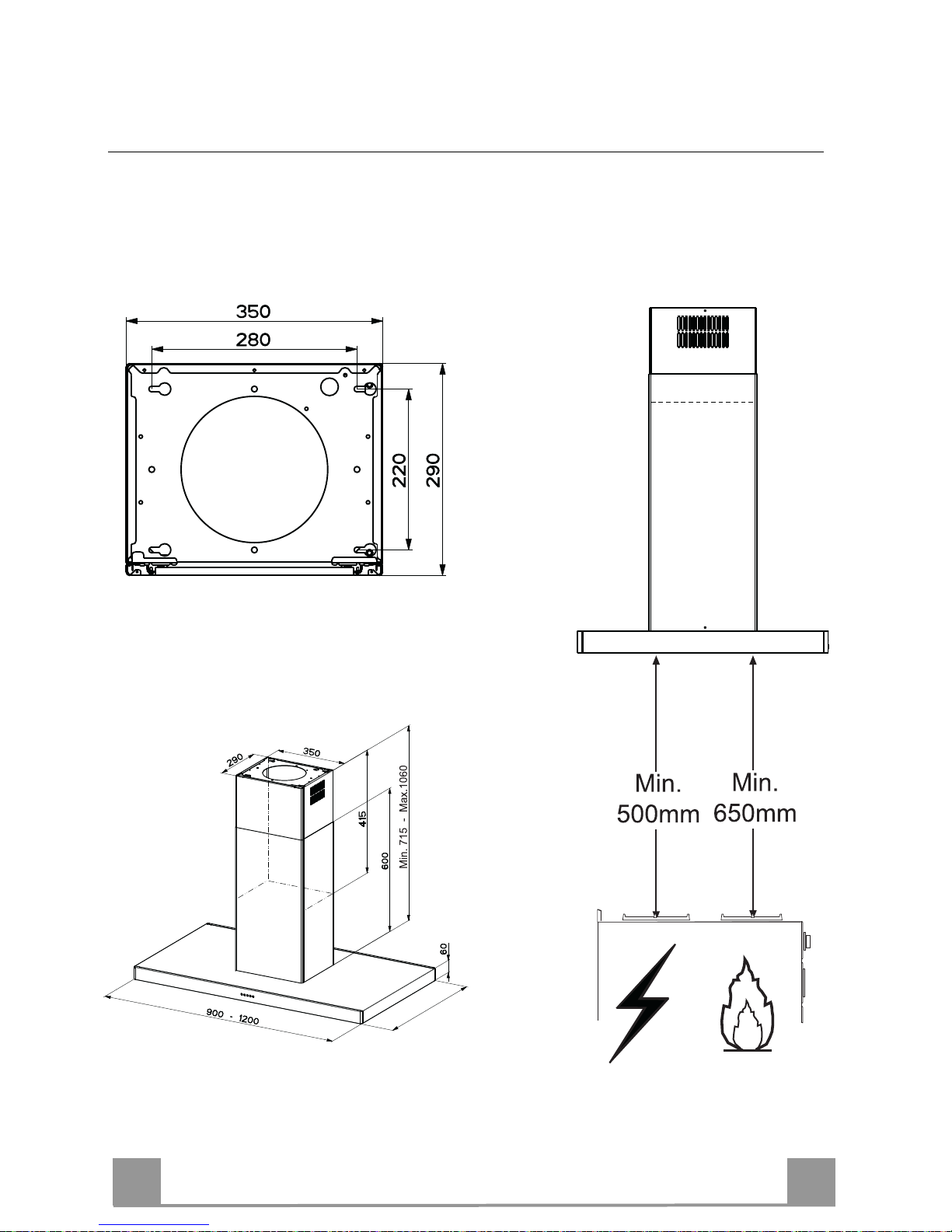
• The minimum safety distance between the cooker top and the extractor hood is 650 mm (some
models can be installed at a lower height, please refer to the paragraphs on working dimensions
and installation).
• Check that the mains voltage corresponds to that indicated on the rating plate fixed to the inside of
the hood.
• For Class I appliances, check that the domestic power supply guarantees adequate earthing.
Connect the extractor to the exhaust flue through a pipe of minimum diameter 120 mm. The route
of the flue must be as short as possible.
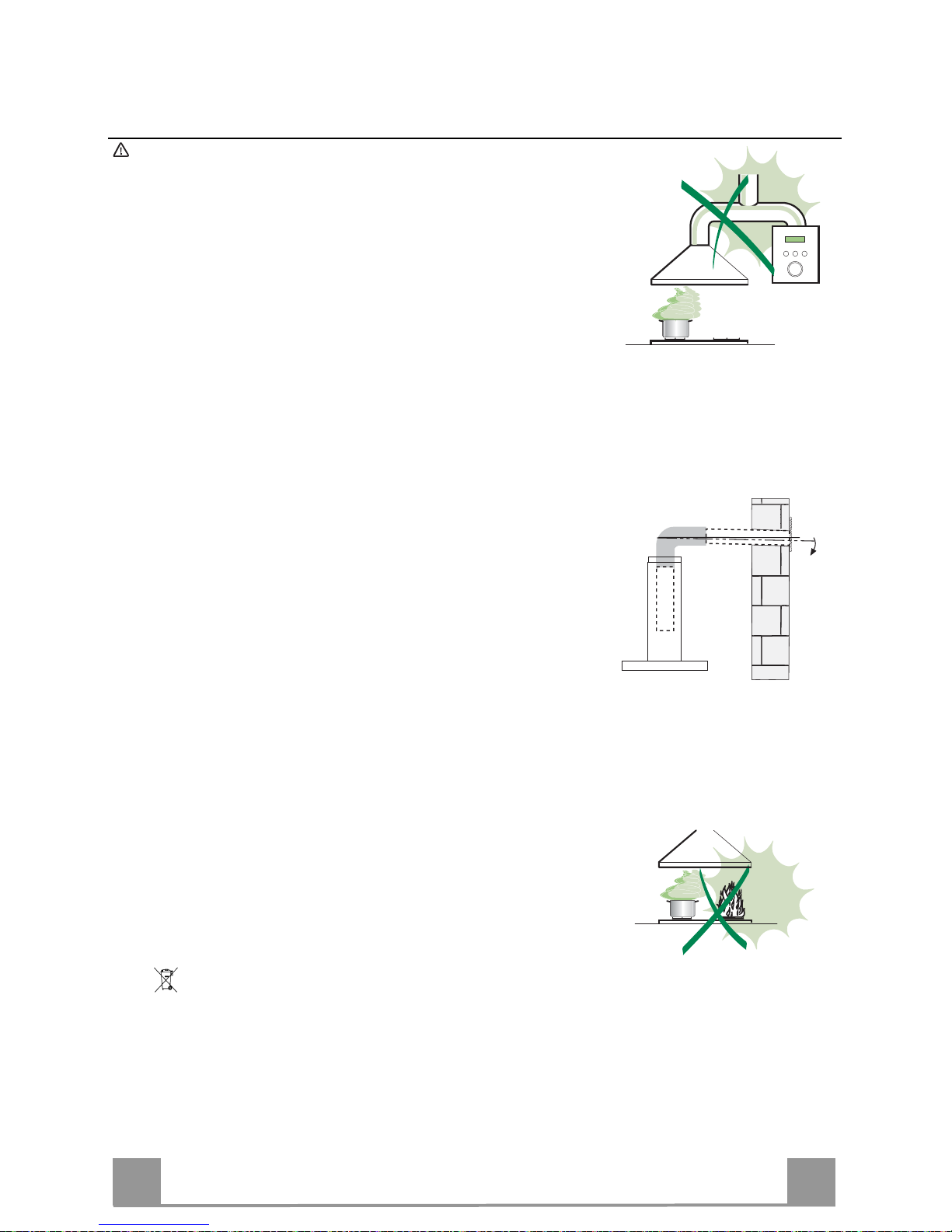
• Do not connect the extractor hood to exhaust ducts carrying combustion fumes (boilers, fireplaces,
etc.).
• If the extractor is used in conjunction with non-electrical appliances (e.g. gas burning appliances), a
sufficient degree of aeration must be guaranteed in the room in order to prevent the backflow of
exhaust gas. The kitchen must have an opening communicating directly with the open air in order
to guarantee the entry of clean air. When the cooker hood is used in conjunction with appliances
supplied with energy other than electric, the negative pressure in the room must not exceed 0,04
mbar to prevent fumes being drawn back into the room by the cooker hood.
• In the event of damage to the power cable, it must be replaced by the manufacturer or by the
technical service department, in order to prevent any risks.
• If the instructions for installation for the gas hob specify a greater distance specified above, this has
to be taken into account. Regulations concerning the discharge of air have to be fulfilled.
USE
• The extractor hood has been designed exclusively for domestic use to eliminate kitchen smells.
• Never use the hood for purposes other than for which it has been designed.
• Never leave high naked flames under the hood when it is in operation.
• Adjust the flame intensity to direct it onto the bottom of the pan only, making sure that it does not
engulf the sides.
• Deep fat fryers must be continuously monitored during use: overheated oil can burst into flames.
• Do not flambè under the range hood; risk of fire
• This appliance is not intended for use by persons (including children) with reduced physical, sensory or mental capabilities, or lack of experience and knowledge, unless they have been given supervision or instruction concerning use of the appliance by a person responsible for their safety.
• Children should be supervised to ensure that they do not play with the appliance.
• “ CAUTION: Accessible parts may become hot when used with cooking appliances.”.
MAINTENANCE
• Switch off or unplug the appliance from the mains supply before carrying out any maintenance
work.
• Clean and/or replace the Filters after the specified time period (Fire hazard).
• Clean the hood using a damp cloth and a neutral liquid detergent.
The symbol on the product or on its packaging indicates that this product may not be treated as household waste. Instead it shall be handed over to the
applicable collection point f or the recycling of electrical and electronic equipment. By ensuring this product is di sposed of correctly, you will help prevent pote ntial negative
consequences for the environme nt and human health, which could otherwi se be caused by inappropriate waste handling of this product. For more detailed information
about recycling of this pr oduct, please contact your local city office, your household wa ste disposal service or the shop where you purchased the prod uct
.
2°
Page 4
EN
4
4
CHARACTERISTICS
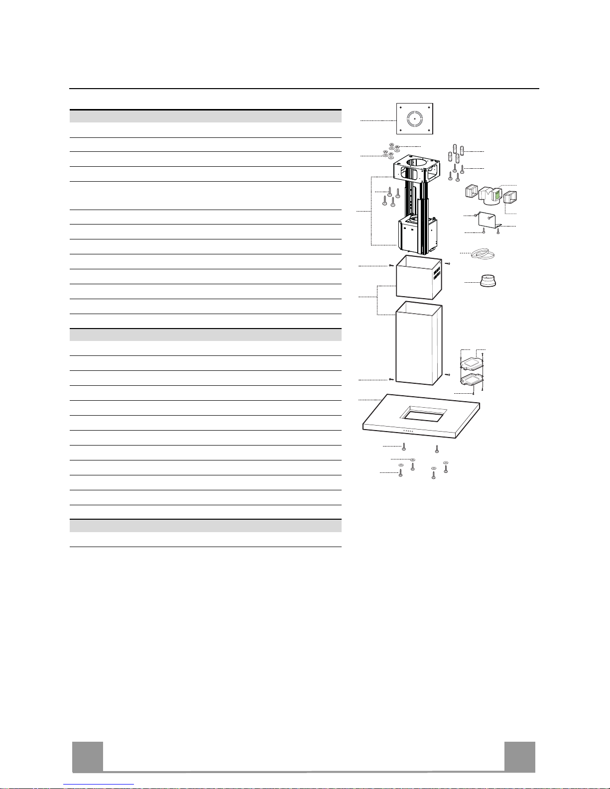
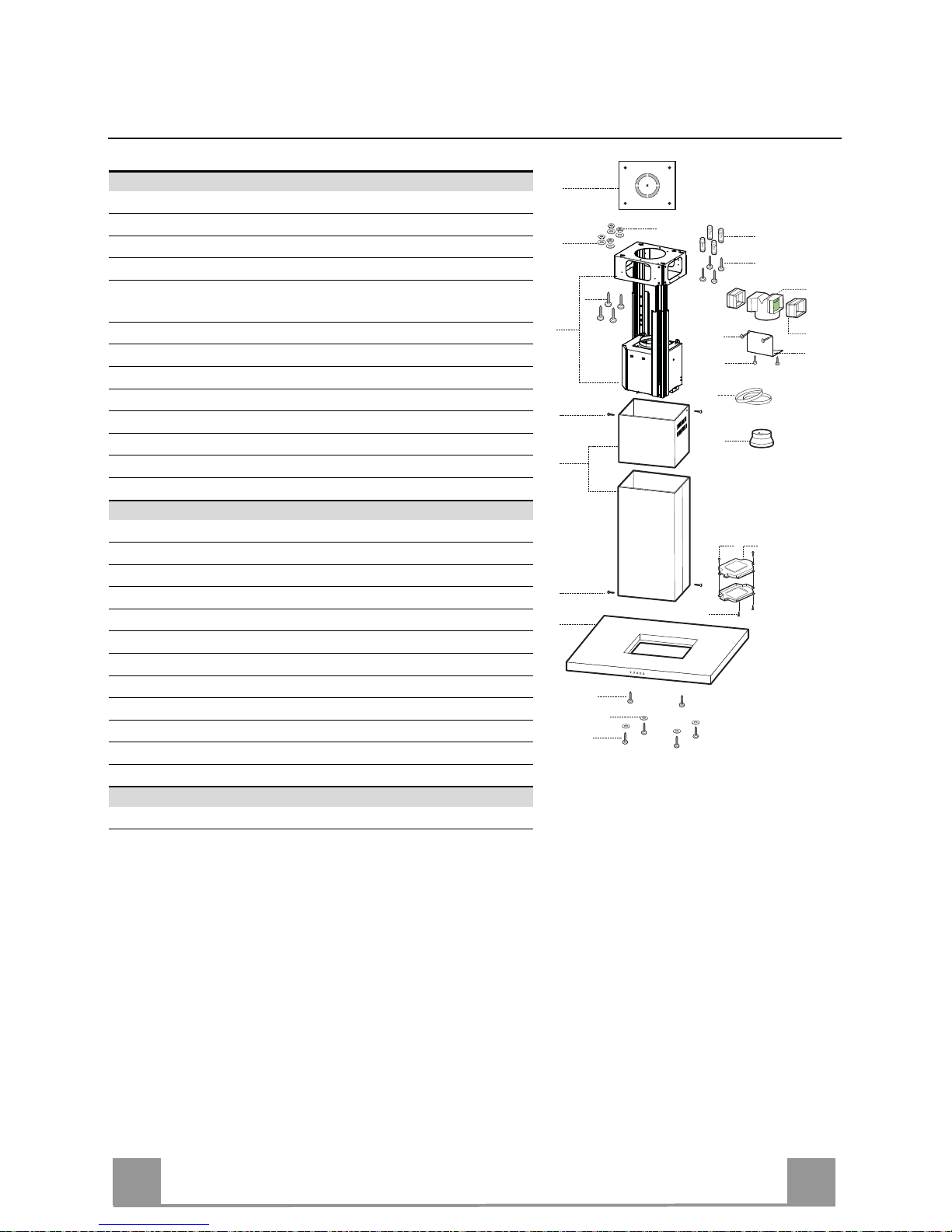
Components
Ref. Q.ty Product Components
1 1 Hood Canopy complete with: Controls, Light, Filters
2 1 Telescopic chimney, made up of:
2.1 1 Upper chimney
2.2 1 Lower chimney
7.1 1 Telescopic frame complete with Suction fan, made up
of:
7.1a 1 Upper frame
7.1b 1 Lower frame
9 1 Reduction flange ø 150-120 mm
14.1 2 Air Outlet Connector Extension
15 1 Air Outlet Connector
24 1 Connection box
25 Hose clamps (not supplied)
Ref. Q.ty Installation Components
7.3 1 Air Outlet Connector fixing bracket
11 4 Wall plugs ø 10
12c 8 Screws 2.9 x 6.5
12e 4 Screws 2.9 x 9.5
12f 2 Screws M4 x 80
12g 4 Screws M6 x 80
12h 4 Screws 5.2 x 70
12q 4 Screws 3.5 x 9.5
21 1 Drilling template
22 8 Washers ø 6.4
23 4 Nuts M6
Q.ty Documentation
1 Instruction Manual
12c
7.1a
7.1
22
23
12h
7.1b
2
2.1
2.2
12c
11
21
12g
1
24
12e
12c
25
9
12f
12q
22
14.1
15
12c
12e
7.3
Page 5

EN
5
5
Dimensions
600
Page 6
EN
6
6
INSTALLATION
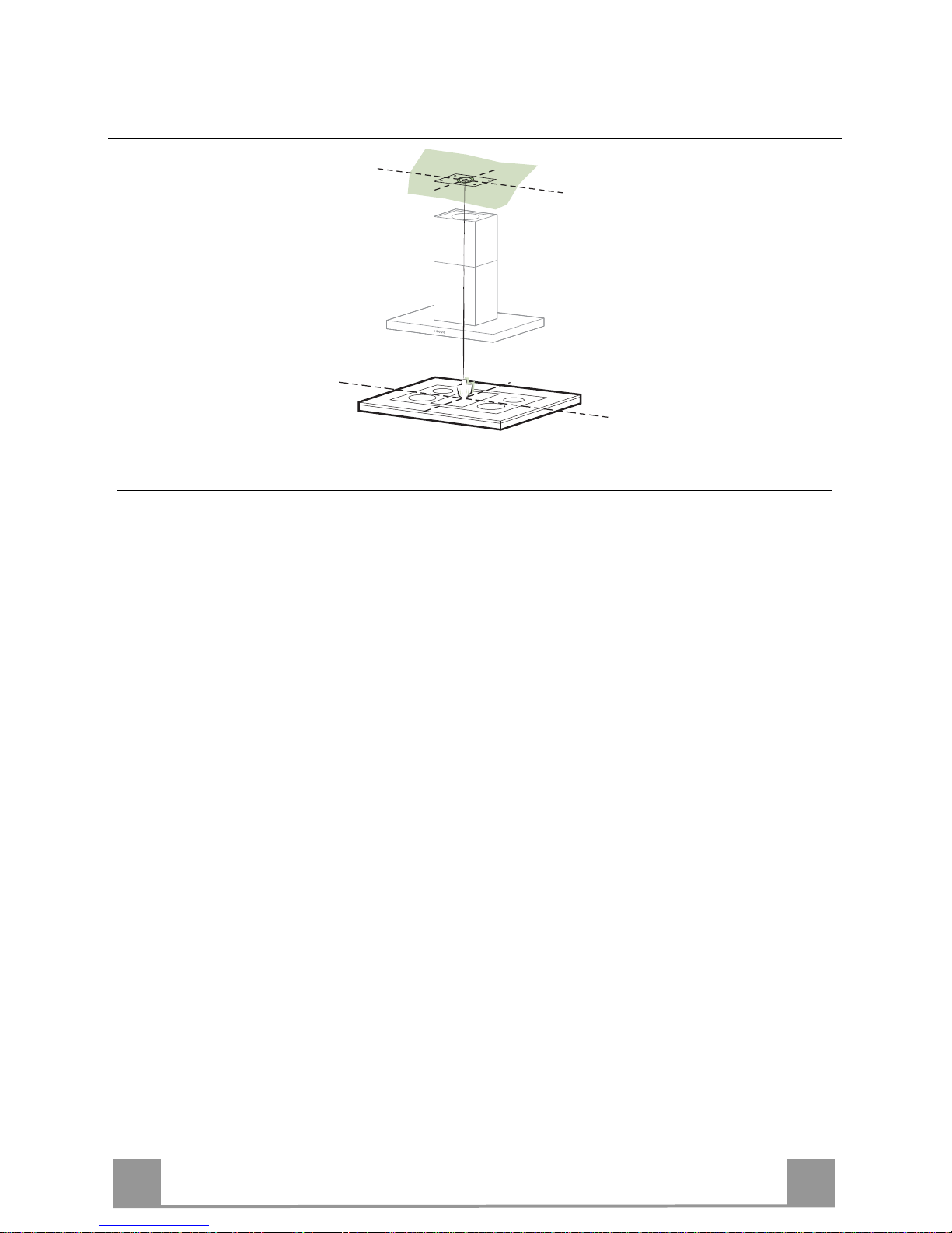
Drilling the Ceiling/shelf and fixing the frame
DRILLING THE CEILING/SHELF
• Use a plumb line to mark the centre of the hob on the ceiling/support shelf.
• Place the drilling template 21 provided on the ceiling/support shelf, making sure that the
template is in the correct position by lining up the axes of the template with those of the hob.
• Mark the centres of the holes in the template.
• Drill the holes at the points marked:
• For concrete ceilings, drill for plugs appropriate to the screw size.
• For hollow brick ceilings with wall thickness of 20 mm: drill ø 10 mm(immediately insert
the Dowels 11 supplied).
• For wooden beam ceilings, drill according to the wood screws used.
• For wooden shelf, drill ø 7 mm.
• For the power supply cable feed, drill ø 10 mm.
• For the air outlet (Ducted Version), drill according to the diameter of the external air ex-
haust duct connection.
• Insert two screws of the following type, crossing them and leaving 4-5 mm from the ceiling:
• For concrete ceilings, use the appropriate plugs for the screw size (not provided).
• for Cavity ceiling with inner space, with wall thickness of approx. 20 mm, Screws 12h,
supplied.
• For wooden beam ceilings, use 4 wood screws (not provided).
• For wooden shelf, use 4 screws 12g with washers 22 and nuts 23, provided.
Page 7

EN
7
7
Fixing the frame
• Loosen the two screws fastening the lower chimney and remove this from the lower frame.
• Loosen the two screws fastening the upper chimney and remove this from the upper frame.
If you wish to adjust the height of the frame, proceed as follows:
• Unfasten the metric screws joining the two columns, located at
the sides of the frame.
• Adjust the frame to the height required, then refit all the screws
removed as above.
• Insert the upper chimney stack from above, and leave it running free on the frame.
• Lift up the frame, fit the frame slots onto the screws up to the
slot end positions.
• Tighten the two screws and fasten the other two screws provided with the hood.
Before tightening the screws completely it is possible to adjust
the frame by turning it. Make sure that the screws do not come
out of their seats in the slotted holes.
• The frame mountings must be secure to withstand the weight
of the hood and any stresses caused by the occasional side
thrust applied to the device.
On completion, check that the base is stable, even if the frame
is subjected to bending.
• In all cases where the ceiling is not strong enough at the suspension point, the installer must provide strengthening using
suitable plates and backing pieces anchored to the structurally
sound parts.
2
2
1
1
Ducted version air exhaust system Connection
When installing the ducted version, connect the hood to the
chimney using either a flexible or rigid pipe ø 150 or 120 mm,
the choice of which is left to the installer.
• To install a ø 120 mm air exhaust connection, insert the reducer flange 9 on the hood body outlet.
• Fix the pipe using the pipe clamps 25 (not provided).
• Remove any activated charcoal filters.
9
ø 150
ø 120
25
25
Page 8
EN
8
8
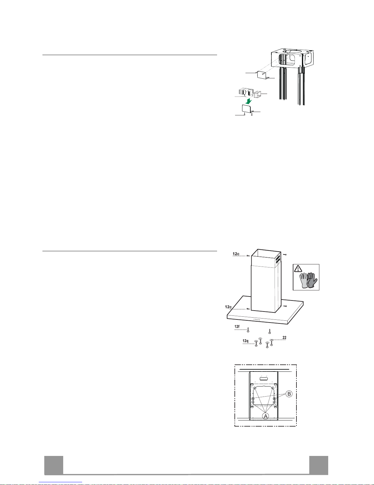
Air outlet – Recirculation Version
• Insert the Connector extensions 14.1 into the side of the
Connector 15.
• Insert the Connector 15 into the Support bracket 7.3 and
fix it with the screws.
• Fasten the Support bracket 7.3, fixing it to the upper
part with the Screws.
• Make sure that the Connector extensions outlet 14.1 is
in correspondence with the Chimney openings both
horizontally and vertically.
• Join the Connector 15 to the Hood canopy outlet using a
rigid or flexible pipe ø¸150 mm, selection of which is at
the discretion of the installation technician.
• Make sure that the Activated charcoal odour filter has
been fitted.
7.3
7.3
12c
12e
15
14.1
Flue assembly - Mounting the hood body
• Position the upper chimney section and fix the upper
part to the frame using the 2 screws 12c (2,9 x 6,5) provided.
• Similarly, position the lower chimney section and fix
the lower part to the frame using the 2 screws 12c (2,9 x
6,5) provided.
Before fixing the hood canopy to the frame:
• Screw the 2 screws 12f half way into the holes provided
in the sides of the bottom of the frame.
• Remove the grease filters from the hood canopy.
• Remove any activated charcoal filters.
• Lift the hood canopy and engage the screws 12f in the
slots (A) as far as they will go.
• Working from below, fix the hood canopy to the frame
(B), using the 4 screws 12q and 4 washers 22 provided,
then tighten all the screws securely.
Page 9
EN
9
9
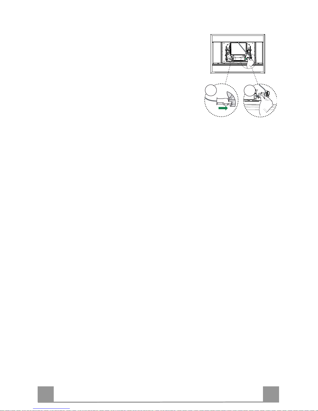
ELECTRICAL CONNECTION
• Connect the Hood to the Mains Power Supply, inserting a
bipolar switch with a contact aperture of at least 3 mm.
• Remove the Grease filters (see paragraph “Maintenance”) and
make sure that the Power cable (A) has been properly inserted
into the Suction fan socket.
• Fasten the connector B to the free socket at the side of the
suction fan
A
B
Page 10
EN
1
10
USE
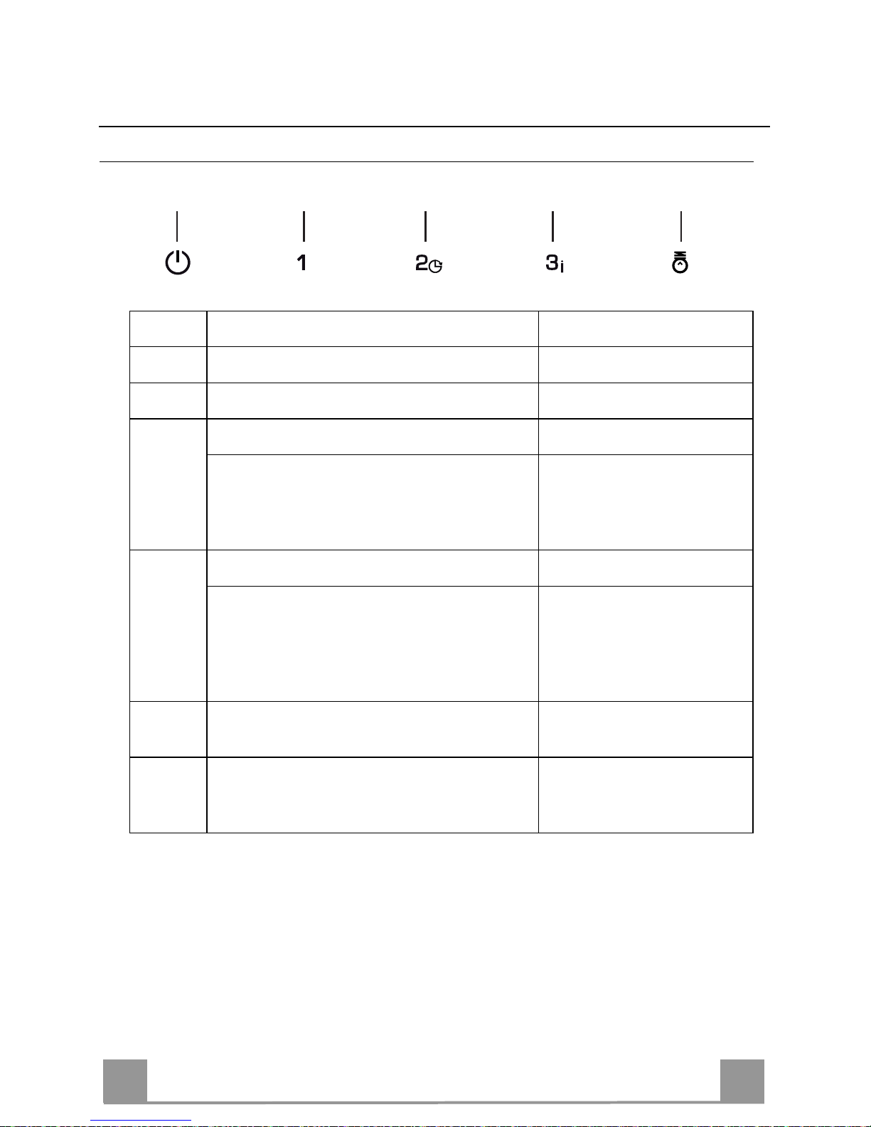
Control panel
T1 T2 T3 T4 L
Button Function
T1
Turns the Motor off.
T2
Turns the motor on at speed one Buttons T1+T2 are lit.
T3
Turns the Motor on at speed two Buttons T1+T3 are lit.
Press and hold for 2 seconds to activate
switch-off with a 30 minute delay (Motor+Lights). It is possible to change the operating speed with this function activated.
Buttons T1+ (T2 or T3 or
T4, respectively) flash.
T4
Turns the Motor on at speed three Buttons T1+T4 are lit.
Press and hold for 2 seconds to activate Intensive speed with a timer set to 10 minutes,
after which it returns to the speed that was
set previously. Suitable to deal with maximum levels of cooking fumes.
The Button flashes.
L
Turns the Lighting system on and off at
maximum intensity.
Button on
Press and hold for 2 seconds to turn the
Lighting system on and off at reduced intensity.
Button on
Page 11
EN
1
11
MAINTENANCE
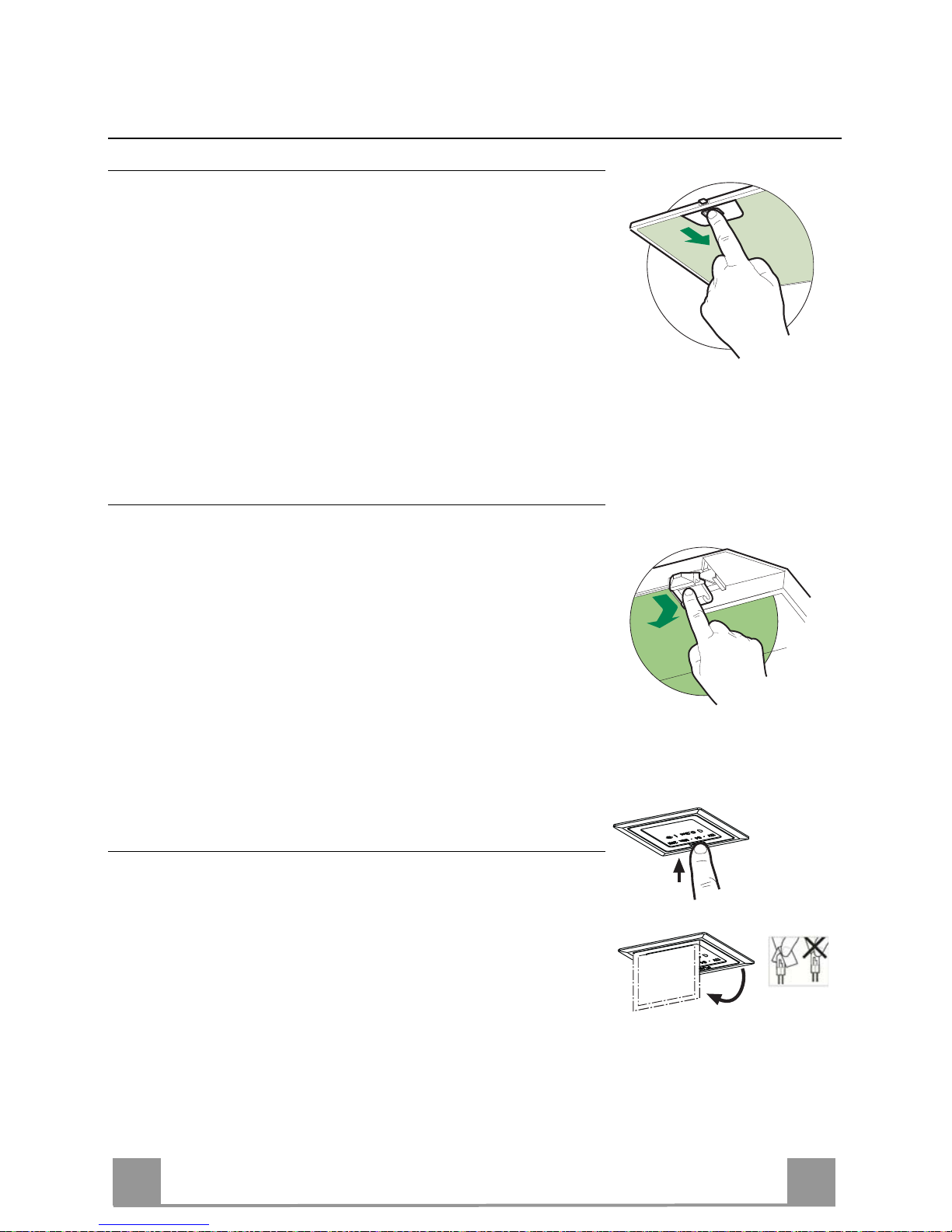
Grease filters
CLEANING METAL SELF- SUPPORTING GREASE FILTERS
• The filters must be cleaned every 2 months of operation, or
more frequently for particularly heavy usage, and can be
washed in a dishwasher.
• Remove the filters one at a time by pushing them towards the
back of the group and pulling down at the same time.
• Wash the filters, taking care not to bend them. Allow them to
dry before refitting.
• When refitting the filters, make sure that the handle is visible
on the outside.
Activated charcoal filter (Recirculation version)
REPLACING THE ACTIVATED CHARCOAL FILTER
• The filter is not washable and cannot be regenerated, and must
be replaced approximately every 4 months of operation, or
more frequently for particularly heavy usage.
• Remove the metal grease filters.
• Remove the saturated activated carbon filter by releasing the
fixing hooks.
• Fit the new filter by hooking it into its seating.
• Refit the metal grease filters.
Lighting
CHANGING LAMPS
Halogen lamps
• Open the spotlight cover.
• Remove the halogen lamp from the lamp holder.
• Replace it with another lamp that has the same characteristics,
making sure that the two pins are inserted properly into the
housings in the lamp holder.
• Close the spotlight cover.
Page 12
IT
1
12
CONSIGLI E SUGGERIMENTI
Questo libretto di istruzioni per l'uso è previsto per più versioni dell' apparecchio. É possibile che siano
descritti singoli particolari della dotazione, che non riguardano il Vostro apparecchio.
INSTALLAZIONE
• Il produttore declina qualsiasi responsabilità per danni dovuti ad installazione non corretta o non conforme
alle regole dell’arte.
• La distanza minima di sicurezza tra il Piano di cottura e la Cappa deve essere di 650 mm, (alcuni modelli
possono essere installati ad un’altezza inferiore, fare riferimento ai paragrafi ingombro e installazione).
• Verificare che la tensione di rete corrisponda a quella riportata nella targhetta posta all’interno della Cappa.
• Per Apparecchi in Classe I
a
accertarsi che l’impianto elettrico domestico garantisca un corretto scarico a
terra.
• Collegare la Cappa all’uscita dell’aria aspirata con tubazione di diametro pari o superiore a 120 mm. Il
percorso della tubazione deve essere il più breve possibile.
• Non collegare la Cappa a condotti di scarico dei fumi prodotti da combustione (caldaie, caminetti, ecc.).
• Nel caso in cui nella stanza vengano utilizzati sia la Cappa che apparecchi non azionati da energia elettrica
(ad esempio apparecchi utilizzatori di gas), si deve provvedere ad una aerazione sufficiente dell’ambiente.
Se la cucina ne fosse sprovvista, praticare un’apertura che comunichi con l’esterno, per garantire il richiamo d’aria pulita. Un uso proprio e senza rischi si ottiene quando la depressione massima del locale non
supera i 0,04 mBar.
• In caso di danneggiamento del cavo alimentazione, esso deve essere sostituito dal costruttore o dal servizio di assistenza tecnica, in modo da prevenire ogni rischio.
• Se le istruzioni di installazione del dispositivo di cottura a gas indicano che è necessaria una distanza
maggiore di quella indicato sopra, è necessario tenerne conto. Bisogna rispettare tutte le normative relative
allo scarico dell’aria.
USO
• La Cappa è stata progettata esclusivamente per uso domestico, per abbattere gli odori della cucina.
• Non fare mai uso improprio della Cappa.
• Non lasciare fiamme libere a forte intensità sotto la Cappa in funzione.
• Regolare sempre le fiamme in modo da evitare una evidente fuoriuscita laterale delle stesse rispetto al
fondo delle pentole.
• Controllare le friggitrici durante l’uso: l’olio surriscaldato potrebbe infiammarsi.
• Non preparare alimenti flambè sotto la cappa da cucina; pericolo d'incendio.
• Questo apparecchio non deve essere utilizzato da persone (bambini inclusi) con ridotte capacità psichiche,
sensoriali o mentali, oppure da persone senza esperienza e conoscenza, a meno che non siano controllati
o istruiti all’uso dell’apparecchio da persone responsabili della loro sicurezza.
• I bambini devono essere supervisionati per assicurarsi che non giochino con l’apparecchio.
• “ATTENZIONE: Le parti accessibili possono diventare molto calde se utilizzate con degli apparecchi di
cottura”.
MANUTENZIONE
• Prima di procedere a qualsiasi operazione di manutenzione, disinserire la Cappa togliendo la spina elettrica o spegnendo l’interruttore generale.
• Effettuare una scrupolosa e tempestiva manutenzione dei Filtri secondo gli intervalli consigliati (Rischio di
incendio).
• Per la pulizia delle superfici della Cappa è sufficiente utilizzare un panno umido e detersivo liquido neutro.
Il simbolo sul prodotto o sulla confezione indica che il prodotto non deve essere considerato come un normale
rifiuto domestico, ma deve essere portato nel punto di raccolta appropriato per il riciclaggio di apparecchiature elettriche
ed elettroniche. Provvedendo a smaltire questo prodotto in modo appropriato, si contribuisce a evitare potenziali conseguenze negative per l’ambiente e per la salute, che potrebbero derivare da uno smaltimento inadeguato del prodotto.
Per informazioni più dettagliate sul riciclaggio di questo prodotto, contattare l’ufficio comunale, il servizio locale di smaltimento rifiuti o il negozio in cui è stato acquist ato il prodotto.
2°
Page 13
IT
1
13
CARATTERISTICHE
Componenti
Rif. Q.tà Componenti di Prodotto
1 1 Corpo Cappa completo di: Comandi, Luce, Filtri
2 1 Camino telescopico formato da:
2.1 1 Camino superiore
2.2 1 Camino inferiore
7.1 1 Traliccio telescopico completo di Aspiratore, formato
da:
7.1a 1 Traliccio superiore
7.1b 1 Traliccio inferiore
9 1 Flangia di riduzione ø 150-120 mm
14.1 2 Prolunga Raccordo Uscita Aria
15 1 Raccordo Uscita Aria
24 1 Scatola connessioni
25 Fascette stringitubo (non incluse)
Rif. Q.tà Componenti di Installazione
7.3 1 Staffa fissaggio Raccordo Uscita Aria
11 4 Tasselli ø 10
12c 8 Viti 2,9 x 6,5
12e 4 Viti 2,9 x 9,5
12f 2 Viti M4 x 80
12g 4 Viti M6 x 80
12h 4 Viti 5,2 x 70
12q 4 Viti 3,5 x 9,5
21 1 Dima di foratura
22 8 Rondelle ø 6,4
23 4 Dadi M6
Q.tà Documentazione
1 Libretto Istruzioni
12c
7.1a
7.1
22
23
12h
7.1b
2
2.1
2.2
12c
11
21
12g
1
24
12e
12c
25
9
12f
12q
22
14.1
15
12c
12e
7.3
Page 14
IT
1
14
Ingombro
600
Page 15

IT
1
15
INSTALLAZIONE
Foratura Soffitto/Mensola e Fissaggio Traliccio
FORATURA SOFFITTO/MENSOLA
• Con l’ausilio di un Filo a piombo riportare sul Soffitto/Mensola di supporto il centro del
Piano di Cottura.
• Appoggiare al Soffitto/Mensola la Dima di Foratura 21 in dotazione, facendo coincidere il
suo centro al centro proiettato e allineando gli assi della Dima agli assi del Piano di Cottura.
• Segnare i centri dei Fori della Dima.
• Forare i punti seguenti:
• Soffitto in Calcestruzzo massiccio: secondo Tasselli per Calcestruzzo impiegati.
• Soffitto in Laterizio a camera d’aria, con spessore resistente di 20 mm: ø 10 mm (inserire
subito i Tasselli 11 in dotazione).
• Soffitto in Travatura di Legno: secondo Viti per Legno impiegate.
• Mensola in Legno: ø 7 mm.
• Passaggio del Cavo elettrico di Alimentazione: ø 10 mm.
• Uscita Aria (Versione Aspirante): secondo diametro del collegamento alla Tubazione di
Evacuazione Esterna.
• Avvitare, incrociandole e lasciando 4-5 mm dal soffitto, due viti:
• per Calcestruzzo massiccio, Tasselli per Calcestruzzo, non in dotazione.
• per Laterizio a camera d’aria, con spessore resistente di 20 mm circa, Viti 12h, in dotazio-
ne.
• per Travatura di legno, Viti per legno, non in dotazione.
• per Mensola in Legno, viti 12g con Rondelle 22 e Dadi 23, in dotazione.
Page 16

IT
1
16
Fissaggio Traliccio
• Svitare le due viti che fissano il camino inferiore e sfilarlo dal
traliccio (dalla parte inferiore).
• Svitare le due viti che fissano il camino superiore e sfilarlo dal
traliccio (dalla parte superiore).
Nel caso in cui si voglia regolare l’altezza del traliccio procedere
come segue:
• Svitare le viti metriche che uniscono le due colonne, poste ai
lati del traliccio;
• Regolare l’altezza desiderata del traliccio e riavvitare le viti
precedentemente tolte;
• Inserire il camino superiore dall’ alto e lasciarlo libero sul traliccio;
• Sollevare il traliccio, incastrare le asole sulle viti e scorrere
fino a battuta;
• Stringere le due viti e avvitare le altre due in dotazione;
Prima di serrare definitivamente le viti è possibile effettuare delle
regolazioni spostando il traliccio, facendo attenzione che le viti
non escano dalla sede dell’asola di regolazione.
• Il fissaggio del Traliccio deve essere sicuro in relazione sia al
peso della Cappa sia alle sollecitazioni causate da occasionali
spinte laterali all’Apparecchio montato. A fissaggio avvenuto
verificare quindi che la base sia stabile anche se il Traliccio è
sollecitato a flessione.
• In tutti i casi in cui il Soffitto non fosse sufficientemente robusto sul punto di sospensione, l’Installatore dovrà provvedere a
irrobustirlo con opportune piastre e contropiastre ancorate a
parti strutturalmente resistenti.
2
2
1
1
Connessione Uscita aria Versione Aspirante
Per installazione in Versione Aspirante collegare la Cappa alla
tubazione di uscita per mezzo di un tubo rigido o flessibile di
ø 150 o 120 mm, la cui scelta è lasciata all’installatore.
• Per collegamento con tubo ø 120 mm, inserire la Flangia di
riduzione 9 sull’Uscita del Corpo Cappa.
• Fissare il tubo con adeguate fascette stringitubo 25(non incluse).
• Rimuovere eventuali filtri al carbone attivo.
9
ø 150
ø 120
25
25
Page 17

IT
1
17
Uscita aria Versione Filtrante
• Inserire lateralmente le Prolunghe Raccordo 14.1 sul
Raccordo 15.
• Inserire il Raccordo 15 nella Staffa di Sostegno 7.3 fis-
sandolo con le Viti.
• Fissare la Staffa di Sostegno 7.3 fissandola con le Viti
alla parte superiore.
• Assicurarsi che l’uscita delle Prolunghe Raccordo 14.1
risulti in corrispondenza delle bocchette del Camino sia
in orizzontale che in verticale.
• Collegare il Raccordo 15 all’Uscita del Corpo Cappa
per mezzo di un tubo rigido o flessibile di ø150 mm, la
cui scelta è lasciata all'installatore.
• Assicurarsi della presenza del Filtro Antiodore al Car-
bone attivo.
7.3
7.3
12c
12e
15
14.1
Montaggio Camino e Fissaggio Corpo Cappa
• Posizionare il Camino superiore e fissare nella parte
superiore al Traliccio con 2 Viti 12c (2,9 x 6,5) in dotazione.
• Analogamente posizionare il Camino inferiore e fissare
nella parte inferiore al Traliccio con 2 Viti 12c (2,9 x
6,5) in dotazione.
Prima di fissare il Corpo Cappa al Traliccio:
• Avvitare per metà le 2 Viti 12f sulla parte inferiore del
traliccio in posizione laterale in corrispondenza dei 2
fori predisposti.
• Togliere i Filtri antigrasso dal Corpo Cappa;
• Togliere eventuali Filtri Antiodore al Carbone attivo.
• Sollevare il Corpo Cappa e incastrare le Viti 12f sulle
asole (rif.A) fino a battuta.
• Fissare da sotto con 4 Viti 12q e 4 Rondelle 22 in dotazione il Corpo Cappa al Traliccio predisposto (rif.B) e
serrare definitivamente tutte le Viti.
Page 18

IT
1
18
CONNESSIONE ELETTRICA
• Collegare la Cappa all’Alimentazione di Rete interponendo un
Interruttore bipolare con apertura dei contatti di almeno 3 mm.
• Rimuovere i Filtri antigrasso (vedi par. “Manutenzione”) e assicurarsi che il connettore del Cavo di alimentazione (A) sia
correttamente inserito nella presa dell’Aspiratore.
• Collegare il connettore B sulla presa rimasta libera a lato
dell’aspiratore
A
B
Page 19

IT
1
19
USO
Quadro comandi
T1 T2 T3 T4 L
Tasto Funzione
T1
Spegne il Motore. -
T2
Accende il motore alla prima velocità I Tasti T1+T2 sono accesi.
T3
Accende il motore alla seconda velocità I Tasti T1+T3 sono accesi.
Premuto per 2 secondi attiva lo spegnimento
ritardato di 30 minuti (Motore+Luci). A funzione attiva è possibile cambiare la velocità di
esercizio.
I rispettivi tasti T1+ (T2 o
T3 o T4) Lampeggiano.
T4
Accende il motore alla terza velocità I Tasti T1+T4 sono accesi.
Premuto per 2 Secondi attiva la velocità Intensiva temporizzata a 10 minuti, al termine dei
quali ritorna alla velocità precedentemente impostata. Adatta a fronteggiare le massime emissioni di fumi di cottura.
Il Tasto lampeggia.
L
Accende e spegne l’Impianto di Illuminazione
alla massima intensità.
Tasto acceso
Premuto per 2 Secondi accende e spegne
l’Impianto di Illuminazione ad intensità ridotta.
Tasto acceso
Page 20

IT
2
20
MANUTENZIONE
Filtri antigrasso
PULIZIA FILTRI ANTIGRASSO METALLICI AUTOPORTANTI
• Sono lavabili anche in lavastoviglie, e necessitano di essere
lavati ogni 2 mesi circa di utilizzo o più frequentemente, per un
uso particolarmente intenso.
• Togliere i Filtri uno alla volta, spingendoli verso la parte posteriore del gruppo e tirando contemporaneamente verso il basso.
• Lavare i Filtri evitando di piegarli, e lasciarli asciugare prima
di rimontarli.
• Rimontarli facendo attenzione a mantenere la maniglia verso la
parte visibile esterna.
Filtro antiodore (Versione Filtrante)
SOSTITUZIONE FILTRO ANTIODORE AL CARBONE ATTIVO
• Non è lavabile e non è rigenerabile, va sostituito almeno ogni 4
mesi o più frequentemente, per un uso particolarmente intenso.
• Togliere i Filtri antigrasso metallici.
• Rimuovere il Filtro antiodore al Carbone attivo saturo, agendo
sugli appositi agganci.
• Montare il nuovo Filtro agganciandolo nella sua sede.
• Rimontare i Filtri antigrasso metallici.
Illuminazione
SOSTITUZIONE LAMPADE
Lampade alogene
• Aprire il coperchio faretto.
• Estrarre la lampadina alogena dal portalampada.
• Sostituirla con una nuova lampadina di uguali caratteristiche,
facendo attenzione ad inserire correttamente i due spinotti nella
sede del portalampade.
• Chiudere il coperchio faretto.
Page 21

FR
2
21
CONSEILS ET SUGGESTIONS
La présente notice d'emploi vaut pour plusieurs versions de l'appareil. Elle peut contenir des descriptions d'ac-
cessoires ne figurant pas dans votre appareil.
INSTALLATION
• Le fabricant décline toute responsabilité en cas de dommage dû à une installation non correcte ou non
conforme aux règles de l’art.
• La distance minimale de sécurité entre le plan de cuisson et la hotte doit être de 650 mm au moins (certains
modèles peuvent être installés à une hauteur inférieure : se reporter aux paragraphes « Encombrement » et
« Installation »).
• Vérifier que la tension du secteur correspond à la valeur qui figure sur la plaquette apposée à l’intérieur de la
hotte.
• Pour les Appareils appartenant à la Ière Classe, veiller à ce que la mise à la terre de l’installation électrique
domestique ait été effectuée conformément aux normes en vigueur.
• Connecter la hotte à la sortie d’air aspiré à l’aide d’une tuyauterie d’un diamètre égal ou supérieur à 120 mm. Le
parcours de la tuyauterie doit être le plus court possible.
• Ne pas connecter la hotte à des conduites d’évacuation de fumées issues d’une combustion tel que (Chaudière, cheminée, etc…).
• Si vous utilisez des appareils qui ne fonctionnent pas à l’électricité dans la pièce ou est installée la hotte (par
exemple: des appareils fonctionnant au gaz), vous devez prévoir une aération suffisante du milieu. Si la cuisine
en est dépourvue, pratiquez une ouverture qui communique avec l’extérieur pour garantir l’infiltration de l’air pur.
Pour un emploi correct et sans risque, la dépression maximum dans la pièce ne doit pas dépasser 0,04 mbar.
• En cas d’endommagement du cordon d’alimentation, faites-le remplacer par le constructeur ou par le service
après-vente, afin de prévenir tout risque.
• Si les instructions de montage pour la plaque de cuisson au gaz spécifient une plus grande distance indiquée cidessus, cela doit être pris en compte. Règlement concernant l'évacuation d'air doivent être remplies..
UTILISATION
• La hotte a été conçue exclusivement pour l’usage domestique, dans le but d’éliminer les odeurs de la cuisine.
• Ne jamais utiliser abusivement la hotte.
• Ne pas laisser les flammes libres à forte intensité quand la hotte est en service.
• Toujours régler les flammes de manière à éviter toute sortie latérale de ces dernières par rapport au fond des
marmites.
• Contrôler les friteuses lors de l’utilisation car l’huile surchauffée pourrait s’enflammer.
• Ne pas préparer d’aliments flambés sous la hotte de cuisine : risque d’incendie
• Cet appareil ne doit pas être utilisé par des personnes (y compris les enfants) ayant des capacités psychiques,
sensorielles ou mentales réduites, ni par des personnes n’ayant pas l’expérience et la connaissance de ce type
d’appareils, à moins d'être sous le contrôle et la formation de personnes responsables de leur sécurité.
• Les enfants doivent être surveillés pour s'assurer qu'ils ne jouent pas avec l'appareil.
• « ATTENTION : Les parties accessibles peuvent devenir très chaudes si utilisées avec des appareils de cuis-
son. »
ENTRETIEN
• Avant de procéder à toute opération d’entretien, retirer la hotte en retirant la fiche ou en actionnant l’interrupteur
général.
• Effectuer un entretien scrupuleux et en temps dû des Filtres, à la cadence conseillée (Risque d’incendie).
• Pour le nettoyage des surfaces de la hotte, il suffit d’utiliser un chiffon humide et détersif liquide neutre.
Le symbole sur le produit ou son emballage indique que ce produit ne peut être traité comme déchet ménager. Il
doit plutôt être remis au point de ramassage concerné, se chargeant du recyclage du matériel électrique et électronique.
En vous assurant que ce produit est éliminé correctement, vous favorisez la prévention des conséquences négatives
pour l’environnement et la santé humaine qui, sinon, seraient le résultat d’un traitement inapproprié des déchets de ce
produit. Pour obtenir plus de détails sur le recyclage de ce produit, veuillez prendre contact avec le bureau municipal de
votre région, votre service d’élimination des déchets ménagers ou le magasin où vous avez acheté le produit.
2°
Page 22

FR
2
22
CARACTERISTIQUES
Composants
Réf. Q.té Composants de Produit
1 1 Corps Hotte équipé de: Comandes, Lumière, Filtres
2 1 Cheminée Télescopique formée de :
2.1 1 Cheminée Supérieure
2.2 1 Cheminée Inférieure
7.1 1 Treillis télescopique avec Aspirateur, formé par:
7.1a 1 Treillis supérieur
7.1b 1 Treillis inférieur
9 1 Flasque de Réduction ø 150-120 mm
14.1 2 Rallonge Raccord Sortie Air
15 1 Raccord Sortie Air
24 1 Boîte connexions
25 Colliers de serrage serre-tube (non compris)
Réf. Q.té Composants pour l’installation
7.3 1 Bride Support Raccord
11 4 Chevilles ø 10
12c 8 Vis 2,9 x 6,5
12e 4 Vis 2,9 x 9,5
12f 2 Vis M4 x 80
12g 4 Vis M6 x 80
12h 4 Vis 5,2 x 70
12q 4 Vis 3,5 x 9,5
21 1 Gabarit de perçage
22 8 Rondelles øi 6,4
23 4 Écrous M6
Q.té Documentation
1 Manuel d’instructions
12c
7.1a
7.1
22
23
12h
7.1b
2
2.1
2.2
12c
11
21
12g
1
24
12e
12c
25
9
12f
12q
22
14.1
15
12c
12e
7.3
Page 23

FR
2
23
Encombrement
600
Page 24

FR
2
24
INSTALLATION
Perçage Plafond/Étagère et Fixation Treillis
PERÇAGE PLAFOND/ETAGERE
• À l’aide d’un Fil à plomb, reporter sur le Plafond/Étagère de support le centre du Plan de
Cuisson.
• Poser contre le Plafond/Étagère le Gabarit de Perçage 21 fourni avec l’appareil, en faisant
coïncider son centre avec le centre projeté et en alignant les axes du Gabarit avec les axes du
Plan de Cuisson.
• Marquer les centres des Trous du Gabarit.
• Percer les trous qui ont été marqués:
• Plafond en Béton massif: en fonction des Goujons pour Béton utilisés.
• Plafond en Briques avec chambre à air, avec épaisseur résistante de 20 mm: ø 10 mm (in-
sérer immédiatement les Chevilles 11 fournies avec l’appareil).
• Plafond en Poutrage en Bois: en fonction des Vis à Bois utilisées.
• Étagère en Bois: ø 7 mm.
• Passage du Câble électrique d’Alimentation: ø 10 mm.
• Sortie Air (Version Aspirante): en fonction du diamètre de la connexion avec les Tuyaux
d’Évacuation Externe.
• Visser deux vis en les croisant et en laissant 4-5 mm. de distance par rapport au plafond:
• pour le Béton massif, des Goujons pour Béton, non fournis avec l’appareil.
• pour Briques percées, ayant une épaisseur résistante de 20 mm. environ, utiliser les Vis
12h, fournies avec l'appareil.
• pour le Poutrage en bois, 4 Vis à bois, non fournies avec l’appareil.
• pour l’Étagère en Bois, 4 Vis 12g avec Rondelles 22 et Écrous 23, fournis avec l’appareil.
Page 25

FR
2
25
FiXATION TREILLIS
• Dévisser les deux vis qui fixent la cheminée inférieure et sortir
cette dernière du treillis (depuis la partie inférieure).
• Dévisser les deux vis qui fixent la cheminée supérieure et sortir
cette dernière du treillis (depuis la partie supérieure).
Si l’on souhaite régler la hauteur du treillis, effectuer les opérations suivantes:
• Dévisser les vis métriques qui unissent les deux colonnes, qui
se trouvent sur les côtés du treillis.
• Régler la hauteur souhaitée du treillis et revisser les vis qui ont
été précédemment retirées.
• Insérer la cheminée supérieure depuis le haut et la laisser libre
sur le treillis.
• Soulever le treillis, encastrer les oeillets sur les vis et faire coulisser jusqu’à la butée;
• Serrer les deux vis et visser les autres deux vis fournies avec
l’appareil;
Avant de serrer définitivement les vis, il est possible d’effectuer
des réglages, en déplaçant le treillis, tout en contrôlant que les vis
ne sortent pas du logement de l’œillet de réglage.
• La fixation du Treillis doit être solide, en fonction du poids de
la Hotte et des contraintes provoquées par les poussées latérales occasionnelles auxquelles l’Appareil monté sera soumis.
Après avoir effectué la fixation, vérifier que la base soit stable,
même si le Treillis est soumis à des contraintes de flexion.
• Dans tous les cas où le Plafond ne devait pas être suffisamment
robuste en correspondance du point d’accrochage, l’Installateur
devra se charger de le rendre plus solide au moyen de plaques
et contre-plaques spéciales, ancrées sur les parties structuralement résistantes.
2
2
1
1
SORTIE AIR VERSION ASPIRANTE
En cas d’installation en version aspirante, brancher la hotte à la
tuyauterie de sortie via un tube rigide ou flexible de ø 150 ou 120
mm, au choix de l’installateur.
• En cas de branchement avec un tube de ø120 mm, insérer le
flasque de réduction 9 sur la sortie du corps de la hotte.
• Fixer le tuyau à l’aide des Colliers de serrage serre-tube 25 (ne
fournis pas).
• Retirer les éventuels filtres anti-odeur au charbon actif.
9
ø 150
ø 120
25
25
Page 26

FR
2
26
Sortie de l’air version filtrante
• Monter latéralement les rallonges du raccord 14.1 sur le
raccord 15 ;
• Placer le raccord 15 dans l’étrier de soutien 7.3 en le
fixant avec les vis ;
• Fixer l’étrier de soutien 7.3 en le fixant avec les vis à la
partie supérieure.
• S’assurer que la sortie des rallonges du raccord 14.1 se
trouve en face des ouvertures du conduit, aussi bien horizontalement que verticalement ;
• Raccorder le raccord 15 à la sortie du corps de hotte au
moyen d’un tuyau rigide ou flexible de 150 mm de
diamètre, au choix de l'installateur ;
• S’assurer de la présence du filtre anti-odeur au charbon
actif.
7.3
7.3
12c
12e
15
14.1
Montage Cheminée - Montage Corps Hotte
• Positionner la Cheminée supérieure et fixer cette dernière dans la partie supérieure du Treillis à l’aide de 2
Vis 12c (2,9 x 6,5) fournies avec l’appareil.
• De la même façon, positionner la Cheminée inférieure
et fixer cette dernière dans la partie inférieure du Treillis à l’aide de 2 Vis 12c (2,9 x 6,5) fournies avec
l’appareil.
Avant de fixer le corps de la hotte au treillis :
• Visser à mi-course les 2 vis 12f sur la partie inférieure du
treillis en position latérale en correspondance des 2 trous
prévus.
• Retirer les filtres à graisse du corps de la hotte.
• Retirer les éventuels filtres anti-odeur au charbon actif.
• Soulever le corps de la hotte et emboîter les vis 12f dans leur
trou (réf.A) jusqu’en butée.
• En passant par dessous, fixer avec les 4 vis 12q et les 4 rondelles 22 fournies le corps de la hotte au treillis prévu (réf.B)
et serrer définitivement toutes les vis.
Page 27

FR
2
27
CONNEXION ÉLECTRIQUE
• Brancher la hotte à l’alimentation du secteur en intercalant un
interrupteur bipolaire avec une ouverture des contacts d’au
moins 3 mm.
• Retirer les filtres à graisse (voir par. « Entretien » et s’assurer
que le connecteur du câble d’alimentation (A) est correctement
branché dans la prise de l’aspirateur.
• Brancher le connecteur B dans la prise restée libre à côté de
l’aspirateur
A
B
Page 28

FR
2
28
UTILISATION
Tableau des commandes
T1 T2 T3 T4 L
Touche Fonction
T1
Coupe le moteur.
T2
Démarre le moteur en première vitesse Les touches T1+T2 sont
allumées.
T3
Démarre le moteur en deuxième vitesse Les touches T1+T3 sont
allumées.
Appuyée pendant 2 secondes, elle active
l’extinction différée de 30 minutes (Moteur +
Éclairage). Lorsque la fonction est active, vous
pouvez varier la vitesse d’exercice.
Les touches respectives
T1+ (T2 ou T3 ou T4) clignotent.
T4
Démarre le moteur en troisième vitesse Les touches T1+T4 sont
allumées.
Appuyée pendant 2 secondes, elle démarre la
vitesse Intensive temporisée à 10 minutes,
après lesquelles le système retourne à la vitesse
précédemment programmée. Fonction indiquée
pour faire face aux pointes d’émission des fumées de cuisson.
La touche clignote.
L
Allume et éteint l’éclairage à l’intensité maximale.
Touche allumée
En appuyant pendant 2 secondes, le système
d’éclairage s’allume et s'éteint à faible intensité.
Touche allumée
Page 29

FR
2
29
ENTRETIEN
Filtres anti-graisse
NETTOYAGE FILTRES ANTI-GRAISSE METALLIQUES AUTOPORTEURS
• Lavables au lave-vaisselle, ils doivent être lavés environ tous
les 2 mois d’emploi ou plus fréquemment en cas d’emploi particulièrement intense.
• Retirer les filtres l’un aprés l’autre, en les poussant vers la partie arrière du groupe et en tirant simultanément vers le bas.
• Laver les filtres en évitant de les plier et les laisser sécher avant
de les remonter.
• Remonter les filtres en veillant à ce que la poignée reste vers la
partie visible externe
Filtre anti-odeur (Version filtrante)
REMPLACEMENT FILTRE AU CHARBON ACTIF
• Ni lavable, ni régénérable, le remplacer au moins tous les 4
mois d’emploi ou plus fréquemment en cas d’emploi particulièrement intense.
• Retirer les filtres anti-graisse métalliques.
• Retirer le filtre anti-odeur au charbon actif colmaté, en agissant
sur les crochets prévus à cet effet.
• Monter le nouveau filtre anti-odeur au charbon actif.
• Remonter les filtres anti-graisse métalliques.
Éclairage
REMPLACEMENT DES AMPOULES
Ampoules à halogène
• Ouvrir le couvercle du spot.
• Retirer l’ampoule à halogène de sa douille.
• La remplacer avec une ampoule neuve ou ayant les mêmes
caractéristiques, en faisant attention d’introduire correctement
les deux broches dans le siège de la douille.
• Refermer le couvercle du spot.
Page 30

DE
3
30
EMPFEHLUNGEN UND HINWEISE
Diese Gebrauchsanleitung gilt für mehrere Geräte-Ausführungen. Es ist möglich, dass einzelne Ausstattungsmerk-
male beschrieben sind, die nicht auf Ihr Gerät zutreffen.
MONTAGE
• Der Hersteller haftet nicht für Schäden, die auf eine fehlerhafte und unsachgemäße Montage zurückzuführen sind.
• Der minimale Sicherheitsabstand zwischen Kochmulde und Haube muss 650 mm betragen (einige Modelle können an einer geringeren Höhe installiert werden, beziehen Sie sich dazu auf den Absatz Platzbedarf und Installation).
• Prüfen, ob die Netzspannung mit dem Wert auf dem im Haubeninneren angebrachten Schild übereinstimmt.
• Bei Geräten der Klasse I ist sicherzustellen, dass die elektrische Anlage des Wohnhauses über eine vorschriftsmäßige Erdung verfügt.
• Das Anschlussrohr der Haube zur Luftaustrittsöffnung muss einen Durchmesser von 120 mm oder darüber aufweisen. Der Rohrverlauf muss so kurz wie möglich sein.
• Die Haube darf an keine Entlüftungsschächte angeschlossen werden, in die Verbrennungsgase (Heizkessel,
Kamine usw.) geleitet werden.
• Werden im Raum außer der Dunstabzugshaube andere, nicht elektrisch betriebene (z.B.
gasbetriebene) Geräte verwendet, muss für eine ausreichende Belüftung gesorgt werden. Sollte
die Küche diesbezüglich nicht entsprechen, ist an einer Aussenwand eine Öffnung anzubringen,
die Frischluftzufuhr gewährleistet. Der Gebrauch ist dann sachgemäß und sicher, wenn der max.
Unterdruck des Raums nicht mehr als 0,04 mbar beträgt.
• Ein schadhaftes Kabel muss vom Hersteller oder vom technischen Kundendienst ausgewechselt werden, damit
jedes Risiko vermieden wird.
• Wenn die Anweisungen für die Installation für die Gaskochgeräts einen größeren Abstand oben angegeben, muss
dies berücksichtigt werden. Vorschriften über die Entlastung der Luft müssen erfüllt sein.
BEDIENUNG
• Die Dunstabzugshaube ist ausschließlich zum Einsatz im privaten Haushalt und zur Beseitigung von Küchengerüchen vorgesehen.
• Unsachgemäßer Einsatz der Haube ist zu unterlassen.
• Große Flammen bei eingeschalteter Haube niemals unbede ckt lassen.
Achtun g! Große Flammen bei eingeschalteter Haube niemals unbedeckt lassen.
• Die Intensivität der Flamme ist so zu regulieren, dass sie den Topfboden nicht überragt.
Achtung! Frittiergeräte müssen während des Gebrauchs stets beaufsichtigt werden: Überhitztes Öl kann
sich entzünden.
• Frittiergerät e müssen während des Gebrauchs stets beaufsichtigt werden: überhitztes Öl kann sich entzünden.
• Keine flambierten Speisen unter der Abzugshaube zubereiten: Brandgefahr.
• Dieses Gerät darf nicht von Personen, auch Kindern, mit verminderten psychischen, sensorischen und geistigern
Fähigkeiten, oder von Personen ohne Erfahrung und Kenntnisse benutzt werden, sofern sie nicht von für ihre Sicherheit verantwortlichen Personen beaufsichtigt und beim Gebrauch des Geräts angeleitet werden.
• Kinder dürfen sich nicht unbeaufsichtigt in der Nähe des Geräts aufhalten und auf keinen Fall mit dem Gerät spielen.
• “ACHTUNG: Die zugänglichen Teile können sehr heiß werden, wenn sie mit Kochgeräten eingesetzt werden.”.
WARTUNG
• Bevor Wartungsarbeiten durchgeführt werden, muss die Stromzufuhr zur Haube unterbrochen werden, indem der
Stecker gezogen oder der Hauptschalter abgeschaltet wird.
• Bei der Filterwartung müssen die vom Hersteller empfohlenen Zeiträume zum Austauschen der Filter genauestens
eingehalten werden (Brandgefahr).
• Zur Reinigung der Haubenflächen Wir empfehlen ein feuchtes Tuch und ein mildes Flüssigreinigungsmittel.
• Bitte keine Reinigungsmittel mit Scheuermittel verwenden. Die Oberfläche wird damit verkratzt.
Das Symbol auf dem Pr odukt oder seiner Verpackung weist darau f hin, dass dieses Produkt nicht als normale r Haushaltsabfall
zu behandeln ist, sondern an einem Sammelpunkt für das Recycling von elektrischen und elektronischen Geräten abgegeben
werden muss. Durch Ihren Beitrag zum korrekten Entsorgen dieses Produkts schützen Sie die Umwelt und die Gesundheit Ihrer
Mitmenschen. Umwelt und Gesundheit werden durch falsches Entsorgen gefährdet. Weitere Informationen über das Recycling
dieses Produkts erhalten Sie von Ihrem Rathaus, Ihrer Müllabfuhr oder dem Geschäft, in dem Sie das Produkt gekauft haben.
2°
Page 31

DE
3
31
CHARAKTERISTIKEN
Komponenten
Pos. St. Produktkomponenten
1 1 Haubenkörper mit Schaltern,
2 1 Teleskopkamin bestehend aus:
2.1 1 oberer Kaminteil
2.2 1 unterer Kaminteil
7.1 1 Teleskopgerüst komplett mit Gebläse, bestehend aus:
7.1a 1 oberer Gerüstteil
7.1b 1 unterer Gerüstteil
9 1 Reduzierflansch ø 150-120 mm
14.1 2 Verlängerung Luftaustritt-Anschlussstück
15 1 Luftaustritt-Anschlussstück
24 1 Verbindungsdose
25 Rohrschellen (nicht enthalten)
Pos. St. Montagekomponenten
7.3 1 Bügel für Anschlusshalter
11 4 Bügel ø 10
12c 8 Schrauben 2,9 x 6,5
12e 4 Schrauben 2,9 x 9,5
12f 2 Schrauben M4 x 80
12g 4 Schrauben M6 x 80
12h 4 Schrauben 5,2 x 70
12q 4 Schrauben 3,5 x 9,5
21 1 Bohrschablone
22 8 Unterlegscheiben ø 6,4
23 4 Schraubenmuttern M6
St. Dokumentation
1 Bedienungsanleitung
12c
7.1a
7.1
22
23
12h
7.1b
2
2.1
2.2
12c
11
21
12g
1
24
12e
12c
25
9
12f
12q
22
14.1
15
12c
12e
7.3
Page 32

DE
3
32
Platzbedarf
600
Page 33

DE
3
33
MONTAGE
Bohren der Decke/Trägerplatte und Montage des Teleskopgerüsts
Achtung: Bitte beachten Sie bei der Montage das Gewicht der kompletten Haube. Die Tragfä-
higkeit der Decke oder alternativ der Trägerplatte für diese Zugbelastung muss vor der Montage geprüft und gegebenenfalls durch die Anbringung von geeigneten Befestigungs- oder
Stabilisierungselementen hergestellt werden. Kann eine hinreichende Tragfähigkeit nicht sichergestellt werden, ist von einer Montage abzusehen.
BOHREN DER DECKE/TRAGERPLATTE
• Mit Hilfe eines Lots den Kochmulden-Mittelpunkt an der Decke oder Trägerplatte ermitteln
und kennzeichnen.
• Die mitgelieferte Bohrschablone 21 so auf die Decke/Trägerplatte legen, dass die Schablonenmitte mit dem gekennzeichneten Mittelpunkt übereinstimmt und die Schablonenseiten
auf die Seiten der Kochmulde ausrichten.
• Die Mitte der Schablonenbohrungen kennzeichnen.
• Die gekennzeichneten Punkte bohren:
• Massivbeton-Decke: je nach verwendeten Beton-Dübeln.
• Decke aus Hohlkammer-Ziegeln mit 20 mm Wandungsstärke: ø 10 mm (sofort die mitge-
lieferten Dübel 11 einfügen).
• Holzbalkendecke: je nach verwendeten Holzschrauben.
• Holz-Trägerplatte: ø 7 mm.
• Durchgang für das Speisekabel: ø 10 mm.
• Luftaustritt (Abluftversion): je nach Durchmesser des Anschlussrohres für die Luftablei-
tung.
• Zwei sich gegenüberliegende Schrauben festziehen und 4-5 mm Freiraum zur Decke belassen:
• bei Massiv-Betondecken mit speziellen Betondübeln, die nicht mitgeliefert werden;
• für Hohlkammer-Ziegeln mit ca. 20 mm Wandungsstärke die mitgelieferten Schrauben
12h verwenden;
• bei Holzbalken-Decken mit 4 Holzschrauben, die nicht mitgeliefert werden;
• bei Holz-Trägerplatten mit 4 Schrauben 12g, Unterlegscheiben 22 und Schraubenmuttern
23, die im Lieferumfang enthalten sind.
Page 34

DE
3
34
Montage des Teleskopgerüsts
• Die beiden Schrauben lösen, die den unteren Gerüstteil fixieren
und diesen aus dem Gerüst ziehen (an der Unterseite)
• Die beiden Schrauben lösen, die den oberen Gerüstteil fixieren
und diesen aus dem Gerüst ziehen (an der Oberseite).
Für eine eventuelle Regulierung der Gerüsthöhe folgendermaßen
vorgehen:
• Die Stellschrauben an den Gerüstseiten, die die beiden Säulen
vereinen, lösen.
• Den oberen Gerüstteil von oben einfügen und frei auf dem Gerüst lassen.
• Das Gerüst heben, die Langlöcher bei den Schrauben einrasten
und bis zum Anschlag laufen lassen;
• Die beiden Schrauben festziehen und die beiden anderen mitgelieferten Schrauben einschrauben;
Bevor die Schrauben definitiv festgezogen werden, kann eine
Regelung durch Bewegen des Gerüstes erfolgen, wobei darauf zu
achten ist, dass die Schrauben nicht aus dem Sitz des Regellangloches austreten.
• Wir verweisen auf die Notwendigkeit einer absolut sicheren
Befestigung des Teleskopgerüsts, die sowohl dem Eigengewicht der Haube wie auch dem seitlichen Druck, der auf das
Gerät einwirken kann, entsprechen muss. Nach erfolgter Montage ist zu prüfen, ob das Teleskopgerüst auch bei Biegebeanspruchung stabil ist.
• Sollte die Decke am Befestigungspunkt nicht robust genug
sein, muss der Installateur geeignete Platten und Gegenplatten
verwenden, die an strukturell widerstandsfähigen Teilen verankert werden.
2
2
1
1
Anschluss in Abluftversion
Bei Abluftbetrieb kann die Haube vom Installateur wahlweise
mittels Rohr oder Schlauch (ø 150 oder 120 mm) an die Außenrohrleitung angeschlossen werden.
• Bei Verwendung eines Anschlussrohres ø 120 den Reduzierflansch 9 am Haubenaustritt anbringen.
• Das Rohr mit den Rohrschellen 25 fixieren (nicht mitgeliefert).
• Eventuell vorhandene Aktivkohlefilter entnehmen.
Achtung! Alle Querschnittänderungen oder Richtungsände-
rungen des Abluftkanals reduzieren die Leistung der Haube.
9
ø 150
ø 120
25
25
Page 35

DE
3
35
Luftaustritt bei der Filterversion
• Die Anschlussverlängerungen 14.1 seitlich am An-
schluss 15 einsetzen.
• Den Anschluss 15 am Haltewinkel 7.3 einsetzen und
mit den Schrauben fixieren.
• Den Haltewinkel 7.3 mit den Schrauben an der Obersei-
te befestigen.
• Sicherstellen, dass sich der Austritt der Anschlussverlängerungen 14.1 sowohl waagrecht als auch senkrecht
auf Höhe der Öffnungen des Kamins befindet.
• Den Anschluss 15 mittels eines starren oder flexiblen
Rohrs mit ø150 mm, das vom Installateur ausgewählt
wird, an den Austritt des Haubenkörpers anschließen.
• Sicherstellen, dass der Aktivkohlefilter zur Geruchsbin-
dung vorhanden ist.
7.3
7.3
12c
12e
15
14.1
Kaminmontage und Montage des Haubenkörpers
• Den oberen Kaminteil positionieren und beim oberen
Gerüstteil mit Hilfe der 2 mitgelieferten Schrauben 12c
(2,9 x 6,5) fixieren.
• Gleichermaßen den unteren Kaminteil positionieren und
beim unteren Gerüstteil mit Hilfe der 2 mitgelieferten
Schrauben 12c (2,9 x 6,5) fixieren.
Vor dem Befestigen des Haubenkörpers am Gitter:
• Die beiden Schrauben 12f halb in die beiden vorbereiteten Löcher seitlich am unteren Gitterabschnitt einschrauben.
• Die Fettfilter aus dem Haubenkörper nehmen.
• Die eventuell vorhandenen Aktivkohlefilter ausbauen.
• Den Haubenkörper anheben, die Schrauben 12f bis zum
Anschlag in die Langlöcher (Bez.A) stecken.
• Den Haubenkörper mit den mitgelieferten 4 Schrauben
12q und 4 Unterlegscheiben 22 von unten am vorbereiteten Gitter (Bez.B) befestigen und alle Schrauben endgültig festschrauben.
Page 36

DE
3
36
ELEKTROANSCHLUSS
Vor der Installation die Netzspannung durch herausdrehen der
Sicherung oder ausschalten des Hauptschalters stromlos machen.
• Beim Anschließen der Haube einen zweipoligen Schalter mit
einer Öffnung der Kontakte von mindestens 3 mm zwischenschalten.
• Die Fettfilter ausbauen (siehe Absatz “Wartung”) und
sicherstellen, dass der Verbinder des Stromkabels (A) richtig
in die Buchse des Abzugs eingesteckt ist.
• Den Verbinder B an der frei gebliebenen Buchse an der Seite
des Abzugs anschließen.
Achtung: Das Gerät nur an die Netzspannung die im Typen-
schild angegeben ist anschließen.
A
B
Page 37

DE
3
37
BEDIENUNG
Schalttafel
T1 T2 T3 T4 L
Taste Funktion
T1
Stellt den Motor ab.
T2
Schaltet den Motor bei der ersten Betriebsgeschwindigkeit ein.
Die Tasten T1+T2 leuchten.
T3
Schaltet den Motor bei der zweiten Betriebsgeschwindigkeit ein
Die Tasten T1+T3 leuchten.
Aktiviert durch 2 Sekunden langes Drücken das
um 30 Minuten verzögerte Abschalten (Motor+Beleuchtung). Bei aktiver Funktion kann
die Betriebsgeschwindigkeit geändert werden.
Die entsprechenden Tasten
T1+ (T2 oder T3 oder T4)
blinken.
T4
Schaltet den Motor bei der dritten Betriebsgeschwindigkeit ein
Die Tasten T1+T4 leuchten.
Aktiviert mit 2 Sekunden langem Drücken die
auf 10 Minuten eingestellte Intensivgeschwindigkeit, nach deren Ablauf wieder zur zuvor
gewählten Gebläsestufe zurückgekehrt wird.
Für die Beseitigung von sehr intensiven Kochdünsten geeignet.
Die Taste blinkt.
L
Schaltet die Beleuchtungsanlage auf höchster
Intensitätsstufe ein und aus.
Taste eingeschaltet
Schaltet bei zirka 2 Sekunden langem Drücken
die verminderte Beleuchtung ein oder aus.
Taste eingeschaltet
Page 38

DE
3
38
WARTUNG
Fettfilter
SELBSTTRAGENDER METALLFETTFILTER REINIGUNG
• Sie müssen nach 2-monatigem Betrieb bzw. bei starkem Einsatz auch häufiger gereinigt werden, was im Geschirrspüler
möglich ist.
• Die Filter nacheinander aushaken, indem sie auf die Rückseite
der Gruppe geschoben und gleichzeitig nach unten gezogen
werden.
• Die Filter reinigen (darauf achten, sie nicht zu verbiegen) und
vor der Remontage trocknen lassen.
• Bei der Remontage ist darauf zu achten, dass sich der Griff auf
der sichtbaren Außenseite befindet.
Geruchsfilter (Umluftversion)
AUSTAUSCHEN DER AKTIVKOHLE FILTER
• Dieser Filter kann weder gewaschen noch wiederverwendet
werden und ist alle 4 Betriebsmonate bzw. bei starkem Einsatz
auch häufiger auszutauschen.
• Die Metallfettfilter entfernen.
• Den gesättigten Aktivkohle-Geruchsfilter aushaken.
• Den neuen Filter in seinem Sitz einhaken.
• Die Metallfettfilter wieder montieren.
Beleuchtung
AUSWECHSELN DER LAMPE
Halogenlampe
• Den Deckel des Strahlers öffnen.
• Die Halogenlampe aus der Lampenfassung nehmen.
• Durch eine neue Lampe mit gleichen Merkmalen ersetzen und
beim Einschrauben darauf achten, dass die beiden Kontakte
richtig in den Sitz der Lampenfassung eingesetzt werden.
• Den Deckel des Strahlers wieder verschließen.
Page 39

TR
3
39
TAVSIYELER VE ÖNERILER
Bu kullanma talimatι birden fazla cihaz modeli için geçerlidir.
Cihazιnιza uymayan bazι donanιm özellikleri tarif edilmiş olabilir.
MONTAJ
• Yalnιş veya eksik montajdan doğan herhangi bir zararιn sorumluluğu üreticiye ait
değildir.
• Davlumbaz ile pişirici cihazιn ocak kιsmι arasιndaki minimum güvenlik mesafesi 650
mm.dir (bazı modeller daha alçak seviyede bir yüksekliğe kurulabilir, hacim ve kurulum ile ilgili paragraflara bakınız).
• Besleme voltajιnιn, davlumbaz içerisine yerleştirilen bilgi etiketinde belirtilenle aynι
olup olmadιğιnι kontrol edin.
• Sιnιf I elektrikli aletleri için, güç kaynağιnιn yeterli topraklamayι sağlayιp
sağlamadιğιnι kontrol edin. Minimum 120 mm çapιnda bir boru yoluyla davlumbazι
çιkιş bacasιna bağlayιn. Baca bağlantιsι
mümkün oldu- ğunca kιsa olmalιdιr.
• Davlumbaz borusunu yanιcι duman taşιyan baca deliğine (buhar kazanι, şömine,
vb.) bağlamayιn.
• Davlumbazιn elektrikle çalιşmayan aletlerle (örneğin; gazlι cihazlar) bağιntιlι olarak
kullanιlmamasι halinde çιkιş gazιnιn geri tepmesini önlemek amacιyla odada yeterli
bir havalandιrma sağlanmalιdιr. Temiz hava girişini temin etmek için mutfakta doğ-
rudan dιşarιya açιlan bir açιklιk bulunmalιdιr. Cihazların bulunduğu mekan ile dış
çevre arasındaki azami basınç farkının 0,04 mbar’
ı geçmemesi şarttır.
• Güç kablosunun hasar görmesi durumunda herhangi bir riskten kaçınmak için ima-
latçı ya da teknik servis tarafından değiştirilmelidir.
• Gaz ocak için montaj talimatları yukarıda belirtilen daha fazla mesafe varsa, bu he-
saba alınmalıdır. Egzoz havası ile ilgili tüm yönetmeliklerle uyumlu olmalıdır.
KULLANIM
• Davlumbaz mutfaktaki kokularιn emilmesi amacιyla evlerde kullanιm için
tasarlanmιştιr.Ticari ve endüstriyel amaçlar için kullanmayιnιz.
• Davlumbazι tasarlandιğι amaçlarιn dιşιnda kesinlikle kullanmayιnιz.
• Davlumbaz çalιşιrken altιnda kesinlikle yüksek çιplak ateş bιrakmayιn.
• Alev yoğunluğunu doğrudan tencerenin altιnda kalacak şekilde ayarlayιn, kenarlarιnι
sarmadιğιndan emin olun.
• Yağ
da kιzartma tavalarιnι kullanιrken sürekli olarak takip edin: fazla ιsιnan yağ tutu-
şabilir.
• Kapağın altında kıvılcımdan kaçının, yangın riski
• Bu alet, güvenliklerinden sorumlu kişiler tarafından kontrol edilmedikleri veya eğitil-
medikleri sürece; fiziksel, duyumsal ve zihinsel kapasitesinde kısıtlama olan (çocuk-
lar dahil) veya aleti kullanma tecrübesi ve bilgisi olmayan kişiler tarafından kullanıla-
maz.
• Bebeklerin, aletle oynamadıklarından emin olmak için kontrol edilmeli gerekir.
• “DİKKAT: Pişirme cihazlarında kullanılırken ulaşılabilir parçalar sıcak hale gelebilir.”
BAKIM
• Herhangi bir bakιm işlemini gerçekleştirmeden önce davlumbazι kapatιn veya fişini
çιkarιn.
• Filtreleri belirtilen zamanlarda temizleyin ve / veya deği
ştirin(Yangın riski).
• Cihazι nemli bir bez ve nötr bir sιvι deterjan kullanarak temizleyin.
Ürün veya paketi üzerindeki sembolü, bu ürünün normal bir evsel atık olarak görülmemesi
ve bu tip elektrikli veya elektronik cihazların atıldığı dönüşümlü toplama noktalarına terkedilmesi
gerektiğine işaret eder. Bu ürünü gerektiği gibi elimine etme kurallarına uyarsanız çevre ve insan
sağlığı üzerindeki olumsuz etkilerini bertaraf etmeye katkı sağlamış olursunuz. Bu ürünün geri
dönüşüm koşulları hakkında daha ayrıntılı bilgi için hudutları içinde bulunduğunuz belediyenin
il
g
ili diaresine, atık yoketme servisine veya ürünün satıcısına danışınız.
2°
Page 40

TR
4
40
ÖZELLIKLER
Parçalar
Ref. Miktar Ürün Aksamı
1 1 Davlumbaz Gövdesi şunlardan oluşur: Kumandalar,
Işık ve Filtreler
2 1 Aşağıda belirtilen unsurları ile birlikte teleskopik baca:
2.1 1 Üst baca
2.2 1 Alt baca
7.1 1 Aspiratörlü teleskopik kafes aşağıdakilerden oluşur:
7.1a 1 Üst kafes
7.1b 1 Alt kafes
9 1 Redüksiyon flanşı ø 150-120 mm
14.1 2 Hava Çıkış Bağlantı Uzatması
15 1 Hava Çıkış Bağlantısı
24 1 Bağlantı kutusu
25 Boru kerpeteni sarıcısı (dahil değil)
Ref. Miktar Kurulum Aksamı
7.3 1 Hava çıkış sabitleme desteği
11 4 Dübel ø 10
12c 8 Vida 2,9 x 6,5
12e 4 Vida 2,9 x 9,5
12f 2 Vida M4 x 80
12g 4 Vidalar M6 x 80
12h 4 Vida 5,2 x 70
12q 4 Vida 3,5 x 9,5
21 1 Delme planı
22 8 Rondela ø 6,4
23 4 Vida somunu M6
Miktar Dokümantasyon
1 Kullanım Kitapçığı
12c
7.1a
7.1
22
23
12h
7.1b
2
2.1
2.2
12c
11
21
12g
1
24
12e
12c
25
9
12f
12q
22
14.1
15
12c
12e
7.3
Page 41

TR
4
41
Boyutlar
600
Page 42

TR
4
42
MONTAJ
Tavan / Konsol delme işlemi ve Kafesin Sabitlenmesi
TAVANIN YADA KONSOLUN DELİNMESİ
• Bir şakül yardımıyla tavana ya da destek konsolüne pişirme tezgahının merkezini işaretleyi-
niz.
• Tavana veya konsola donanımla birlikte verilen delik delme şablonunu (21) dayayınız ve
bunun merkeziyle işaretlenen merkezi birbirine çakıştırınız. Yani şablonun ekseni ile pişir-
me tezgahı ekseni bir hizaya gelmiş olsun.
• Delik delme şablonuyla delikleri duvara işaretleyiniz.
• Şu şekilde delik deliniz:
• Masif beton tavan: beton dübelleri kullanarak.
• Direnç kalınlığı 20 mm ve üstte hava boşluğu olan tuğla tavan: 10 mm çapında delik (do-
nanımla verilmiş dübelleri (11) hemen takınız)
• Ahşap tavan: ahşap dübelleri kullanarak.
• Ahşap konsola: 7 mm çapında delik deliniz.
• Elektrik besleme kablosunun geçişi için: ø 10 mm çapı
nda.
• Hava Çıkışı (Aspiratörlü model): Dış hava tahliye borusu bağlantısının çapına göre.
• Tavana çaprazlamasına iki vida takıp 4-5 mm dışarıda bırakınız. Bu vidalar şöyle olmalıdır:
• Masif beton için buna uygun vida ve dübeller; bunlar donanımla verilmemiştir.
• Hava boşluklu tuğla tavan - yaklaşık 20 mm direnç kalınlıklı - bunun için donanımla ve-
rilmiş vidaları (12h) kullanınız.
• Ahşap tavana uygun vidalar: donanımda yoktur.
• Ahşap konsola: donanımdaki vidalar (12g), rondelalar (22) ve cıvatalar (23).
Page 43

TR
4
43
Kafesin Sabitlenmesi
• Alt bacayı sabitleyen iki adet vidayı söküp kafesten çıkarınız
(alt kısımdan).
• Üst bacayı sabitleyen iki adet vidayı söküp kafesten çıkarınız
(üst kısımdan).
Kafesin yüksekliği ayarlanmak istenirse, şu şekilde hareket edilmelidir:
• Kafesin iki yanında bulunan sütunları birleştiren adet metrik
vidayı sökünüz;
• Kafesin yüksekliğini istediğiniz seviyede ayarlayıp daha önce
sökmüş olduğunuz adet vidayı tekrar takarak sıkınız;
• Yukarı kısımdan üst bacayı geçiriniz ve kafes üzerinde serbest
bırakınız;
• Kafesi yukarı kaldırınız, delikleri vidalara geçirip dayanana
kadar kaydırını
z;
• İki adet vidayı sıkıp bilahare cihaz donanımıyla verilmiş olan
iki adet diğer vidayı da takınız;
Vidaları nihai olarak sıkmadan önce, kafesi ayar delikleri vidalardan çıkmadan kaydırmaya özen göstererek ayarlamak mümkündür.
• Kafesin sabitlenmesi hem Davlumbazın ağırlığını kaldırabile-
cek, hem de cihazın montajından sonra yandan gelebilecek
sarsmalara dayanacak şekilde mümkün olduğunca sağlam yapılmalıdır. Sabitleme işlemi bittikten sonra, Kafesi sarsınca ve
esnetince bile kaidenin sabit ve sağlam şekilde durduğunu
kontrol ediniz.
• Askı noktasında tavanın yeterince sağlam olmadığı hallerde,
montör buraya uygun sıkı bağ
lantılı levha ve plakalar uygula-
mak suretiyle tavan sağlamlığını arttırma yoluna gitmelidir.
2
2
1
1
Aspiratörlü Model Hava Çıkışı Bağlantısı
Aspiratörlü modelin bağlantısını yapmak için, davlumbazı ø 150
yada 120 mm çapında, montörün seçimine göre sert veya esnek
bir boruyla çıkış kanalına bağlayınız.
• ø 120 mm çapında boruyla bağlantı için, redüksiyon flanşını 9 dav-
lumbaz gövdesi çıkışına takınız.
• Boruyu uygun boru kelepçeleri 25 ile sabitleyin (dahil değildir).
• Varsa aktif karbon filtrelerini çıkartınız.
9
ø 150
ø 120
25
25
Page 44

TR
4
44
Filtre Edici Versiyon Hava Çıkışı
• 14.1 ekleme bileziği uzatmalarını yanal olarak 15 no.lu
ekleme bileziğine sokunuz.
• Vidaları sabitleyerek 15 no.lu bağlantıyı 7.3 Destek
Dirseğine ekleyiniz.
• 7.3 Destek dirseğini vidalarla üst bölüme sabitleyiniz.
• 14.1 ekleme bileziği uzatmaları çıkışının, gerek yatay,
gerekse dikey olarak, baca mentezlerinin hizasında
bulunduğundan emin olunuz.
• 15 no.lu Bağlantıyı, montaj görevlisinin seçimine göre
ø150 mm çapında sert veya esnek bir hortum ile Davlumbaz Gövdesi Çıkışına bağlayınız.
• Aktif Karbonlu Koku önleyici Filtrenin bulunduğundan
emin olunuz.
7.3
7.3
12c
12e
15
14.1
Baca montajı ve davlumbaz gövdesinin sabitlenmesi
• Üst Bacayı yerleştiriniz ve cihaz donanımındaki 2 adet
vidayı 12c (2,9 x 6,5) kullanarak yukarı kısımdan Kafese sabitleyiniz.
• Aynı şekilde alt Bacayı da yerleştiriniz ve cihaz donanımındaki 2 adet vidayı 12c (2,9 x 6,5) kullanarak aşağı kısımdan Kafese sabitleyiniz.
Davlumbaz Gövdesini Kafesli Izgaraya sabitlemeden önce:
• 2 adet 12f vidayı, yan konumda kafesin alt bölümünde
mevcut 2 deliğe yarı şekilde vidalayın.
• Davlumbaz gövdesinden yağlanmaya karşı filtreleri çı-
kartın;
• Olası Aktif Karbonlu Kokuya Karşı Filtreleri Çıkartın.
• Davlumbaz Gövdesini kaldırın ve 12f vidaları yuvalara
(ref.A) oturtun.
• Donanımda mevcut olan 4 adet
12q vida ile ve 4 adet
rondela 22 rondela ile davlumbaz gövdesini kafese
sabitleyin (ref. B) ve tüm vidaları iyice sıkıştırın.
Page 45

ELEKTRİK BAĞLANTISI
• Davlumbazı, en az 3 mm kontak açılmalı çift kutuplu anahtarla
Şebeke Beslemesine bağlayın.
• Yağlanmaya Karşı Filtreleri çıkartın (Bkz. “Bakım” bölümü)
ve besleme Kablosunun konnektörünün (A) Aspiratöre doğru
şekilde bağlandığından emin olun.
• Konnektörü B boş ucunu aspiratörün yan tarafına bağlayın.
A
B
Page 46

TR
4
46
KULLANIM
Kumanda panosu
T1 T2 T3 T4 L
Tuş Fonksiyon
T1
Motoru durdurur.
T2
Birinci hızda motoru çalıştırır. T1+T2 tuşları yanar.
T3
İkinci hızda motoru çalıştırır. T1+T3 tuşları yanar.
2 Saniye basılması 30 dakikalık uyku modunun
etkinleşmesini sağlar (Motor + Işıklar). Bir
fonksiyon aktifken işlem hızını değiştirebilirsi-
niz.
İlgili tuşlar T1+ (T2 veya
T3 veya T4) yanıp söner.
T4
Üçüncü hızda motoru çalıştırır T1+T4 tuşları yanar.
2 Saniye basmak 10 dakika için yoğun hızda
çalışmayı etkin duruma getirir. Bu sürenin sonunda, ayarlanmış olan bir önceki hıza geri döner. Pişirme sırasındaki dumanın fazla yayıl-
masını engellemek için uygundur.
Tuş yanıp söner.
L
Aydınlatma tesisatını maksimum yoğunlukta
açar ve kapatır.
Tuş ışığı açık
2 Saniye basılı tutulunca aydınlatma tesisatını
düşük yoğunlukta açar ve kapatır.
Tuş ışığı açık
Page 47

TR
4
47
BAKIM
Yağ tutucu filtreler
METALİK YAĞ TUTUCU FİLTRELERİN TEMİZLENMESİ
• Bu filtreler bulaşık makinasında da yıkanabilir ve normal kullanıldıklarında iki ayda bir, yoğun kullanım halinde ise daha
sıkça yıkanmalarıı gereklidir.
• Filtrleri, grubun arka tarafından ittirerek ve aynı anda aşağı
doğru çekerek tek tek çıkarınız.
• Filtreleri yıkarken eğip katlamayınız, tekrar monte etmeden
önce de kurutunuz.
• Monte ederken kulpun görünen dış tarafa doğru gelmesine dik-
kat ediniz.
Koku Filtresi (Filtreli Model)
AKTİF KARBONLU KOKU FİLTRESİNİN DEĞİŞTİRİLMESİ
• Yıkanabilir ya da rejenere edilebilir nitelikte değildir, normalde
en az 4 ayda bir, yoğun kullanımda ise daha sıkça değiştirilir.
• Metalik Yağ Filtrelerini çıkarınız.
• Doymuş durumdaki Aktif Karbonlu Koku Filtresini kancalarını
serbest bırakarak çıkarınız.
• Yeni filtreyi yuvasına takınız.
• Metalik Yağ Filtrelerini tekrar monte ediniz.
Aydınlatma
LAMBALARIN DEĞİŞTİRİLMESİ
Halojen Lambalar
• Spot kapağını açınız.
• Lamba yuvasından lambayı çıkartınız.
• Destek yuvasındaki iki ucun doğru bir şekilde yerleştirilmesine
dikkat ederek lambayı aynı özelliklere sahip başka bir lamba
ile değiştiriniz.
• Spot kapağını kapatınız.
Page 48

991.0264.320_ver2
Franke S.p.a.
Via Pignolini,2
37019 Peschiera del Garda (VR)
www.franke.it
 Loading...