

Page 1

Instructions for use and installation
Cooker Hood
Istruzioni per l’uso e l’installazione
Cappa
Mode d’emploi et installation
Hotte de Cuisine
Bedienungsanleitung und Einrichtung
Dunstabzugshaube
Kullan
ım ve montaj talimatları
Davlumbaz
FCR 908 TC
IT
FR
DE
TR
GB
Page 2

2
2
INDEX
RECOMMENDATIONS AND SUGGESTIONS......................................................................................................................3
CHARACTERISTICS..............................................................................................................................................................4
INSTALLATION ......................................................................................................................................................................5
USE.........................................................................................................................................................................................8
MAINTENANCE......................................................................................................................................................................9
INDICE
CONSIGLI E SUGGERIMENTI ............................................................................................................................................11
CARATTERISTICHE............................................................................................................................................................12
INSTALLAZIONE..................................................................................................................................................................13
USO......................................................................................................................................................................................16
MANUTENZIONE.................................................................................................................................................................17
SOMMAIRE
CONSEILS ET SUGGESTIONS ..........................................................................................................................................19
CARACTERISTIQUES.........................................................................................................................................................20
INSTALLATION ....................................................................................................................................................................21
UTILISATION........................................................................................................................................................................24
ENTRETIEN..........................................................................................................................................................................25
INHALTSVERZEICHNIS
EMPFEHLUNGEN UND HINWEISE....................................................................................................................................27
CHARAKTERISTIKEN..........................................................................................................................................................28
MONTAGE............................................................................................................................................................................29
BEDIENUNG.........................................................................................................................................................................32
WARTUNG............................................................................................................................................................................33
IÇERIKLER
TAVSIYELER VE ÖNERILER ..............................................................................................................................................35
ÖZELLIKLER........................................................................................................................................................................36
MONTAJ...............................................................................................................................................................................37
KULLANIM............................................................................................................................................................................40
BAKIM...................................................................................................................................................................................41
EN
IT
FR DE TR
Page 3
EN
3
3
RECOMMENDATIONS AND SUGGESTIONS
The Instructions for Use apply to several versions of this appliance. Accordingly,
you may find descriptions of individual features that do not apply to your specific
appliance.
INSTALLATION
• The manufactu rer will not b e h eld lia ble for any damages res ultin g from in correc t or
improper inst allation.
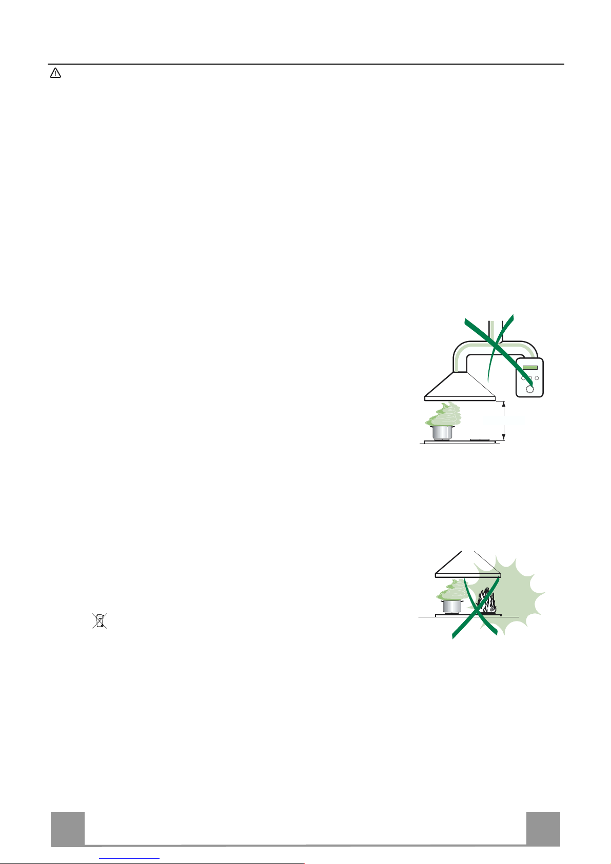
• The minimum safety distance between the cooker top and the extractor hood is 650
mm.
• Check that the mains voltage corresponds to that indicated on the rating plate fixed
to the inside of the hood.
• For Class I appliances, check that the domestic power supply guarantees adequate
earthing.
Connect the extractor to the exhaust flue through a pipe of minimum diameter 120
mm. The route of the flue must be as short as possible.
• Do not connect the extractor hood to exhaust ducts carrying combustion fumes
(boilers, fireplaces, etc.) .
• If the extractor is used in conjunction with non-electrical appliances (e.g. gas burning appliances), a sufficient degree of aeration must be guaranteed in the room in
order to prevent the backflow of exhaust gas. The kitchen must have an opening
communicating directly with the open air in order to guarant ee the entry of clean air.
USE
• The extractor hood has been designed exclusively for domestic use to eliminate
kitchen smells.
• Never use the hoo d for purposes ot her than for whic h i t has ben designed.
• Never leave high naked flames under the hood when it is in oper ation.
• Adjust the flame intensity to direct it onto the bottom of the pan only, making sure
that it does not engulf the sides.
• Deep fat fryers must be continuously moni tored during use: overheated oil can burst
into flames.
• Do not flambè und er the range hood; risk of fire
• This appliance is not intended for use by persons (including children) with reduced
physical, sensory or mental capabilities, or lack of experience and knowledge,
unless they have been given supervision or instruction concerning use of the appliance by a person responsible f or their safety.
• Children should be supervised to ensure that they do not play w ith the appliance.
MAINTENANCE
• Switch off or unplug the appliance from the mains supply before carrying out any
maintenance work.
• Clean and/or repl ace the Filter s after the specified time peri od.
• Clean the hood usi ng a damp cloth and a neutral l iquid detergent .
The symbol on the product or on its packaging indicates that this product may not be treated as
household waste. Instead it shall be handed over to the applicable collection point for the recycling
of electrical and electronic equipment. By ensuring this product is disposed of correctly, you will help
prevent potential negative consequences for the environment and human health, which could otherwise be caused by inappropriate waste handling of this product. For more detailed information about
recycling of this product, please contact your local city office, your household waste disposal service
or the shop where you purchas ed the product.
650 mm min.
Page 4
EN
4
4
CHARACTERISTICS
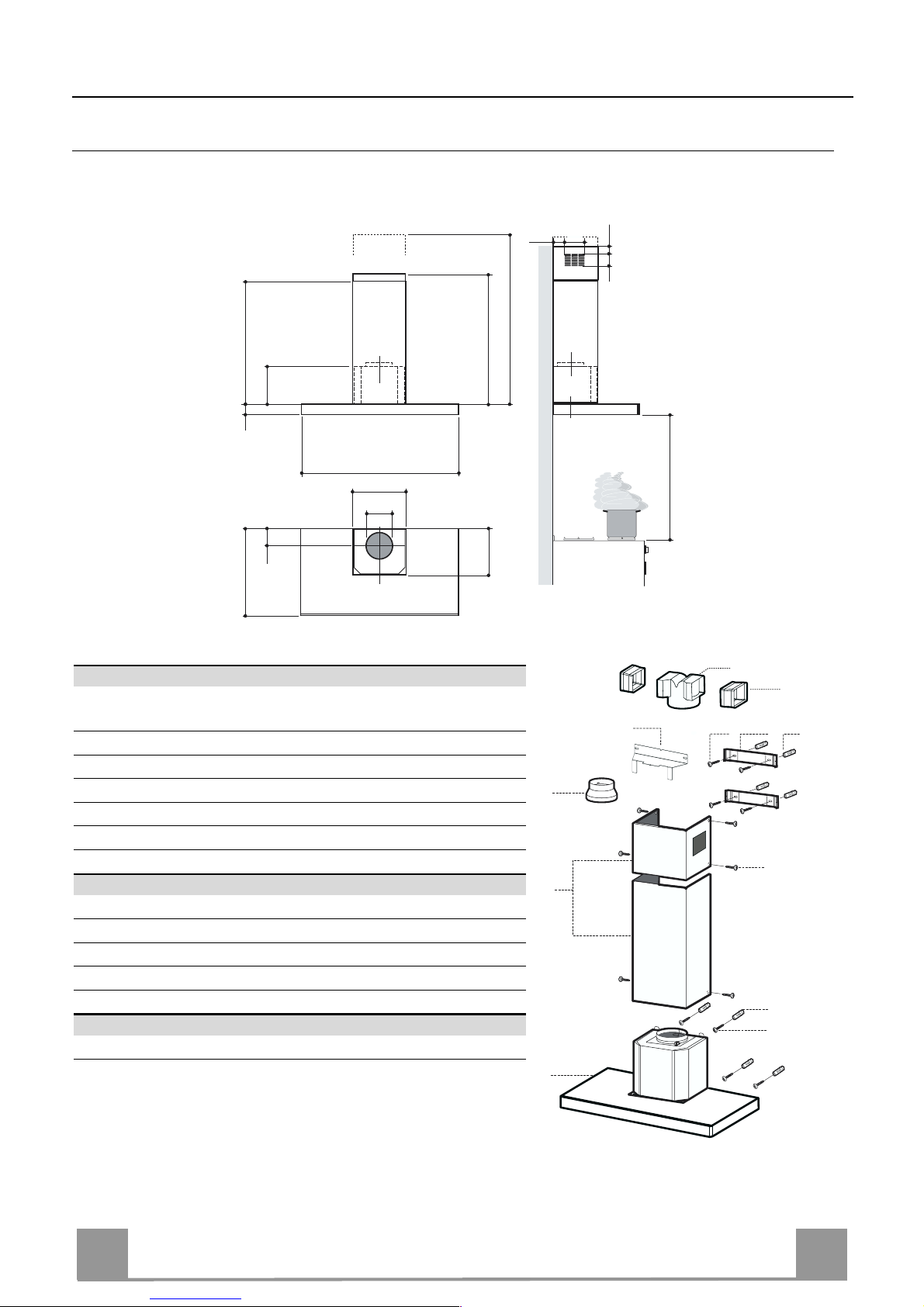
Dimensions
650 min.
485
60
108 259
150
min. 670
max. 1000
540
260
300
898
6341126
81
Components
Ref. Q.ty Product Components
1 1 Hood Body, complete with: Controls, Light, Blower,
Filters
2 1 Telescopic Chimney comprising:
2.1 1 Upper Section
2.2 1 Lower Section
9 1 Reducer Flange ø 15 0-120 mm
14.1 2 Air Outlet Connect ion Extension
15 1 Air Outlet Connect ion
Ref. Q.ty Installation Components
7.2.1 2 Upper Chimney Section Fixing Brackets
7.3 1 Air Outlet Connect ion Support
11 8 Wall Plugs
12a 8 Screws 4,2 x 44,4
12c 6 Screws 2,9 x 9,5
Q.ty Documentation
1 Instruction Manual
2.1
2.2
2
12c
12a
7.2.1 11
11
12a
1
9
7.3
14.1
15
Page 5
EN
5
5
7.3
11
12a
320
X
116
1÷2
116
650 min.
7.2.1
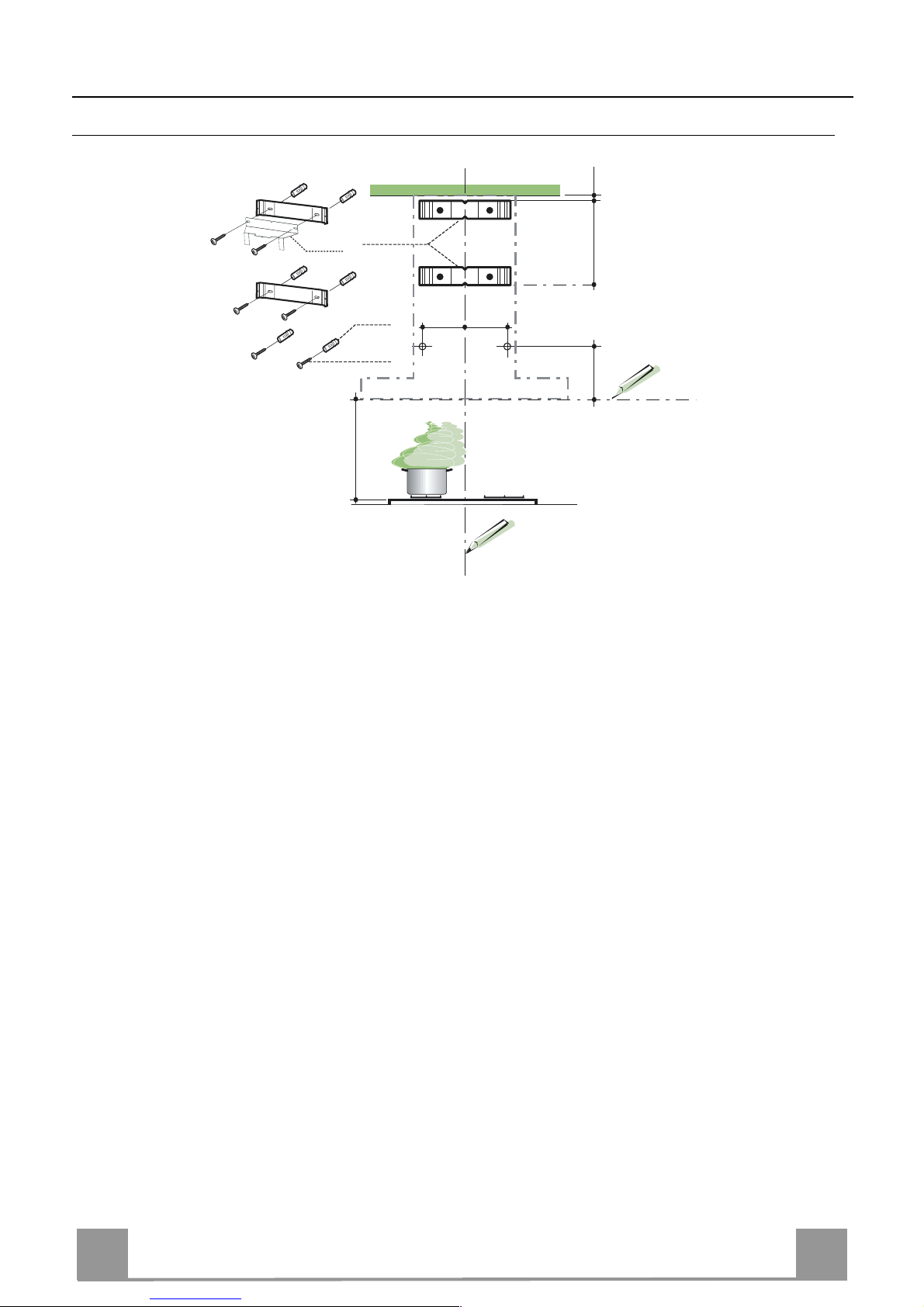
INSTALLATION
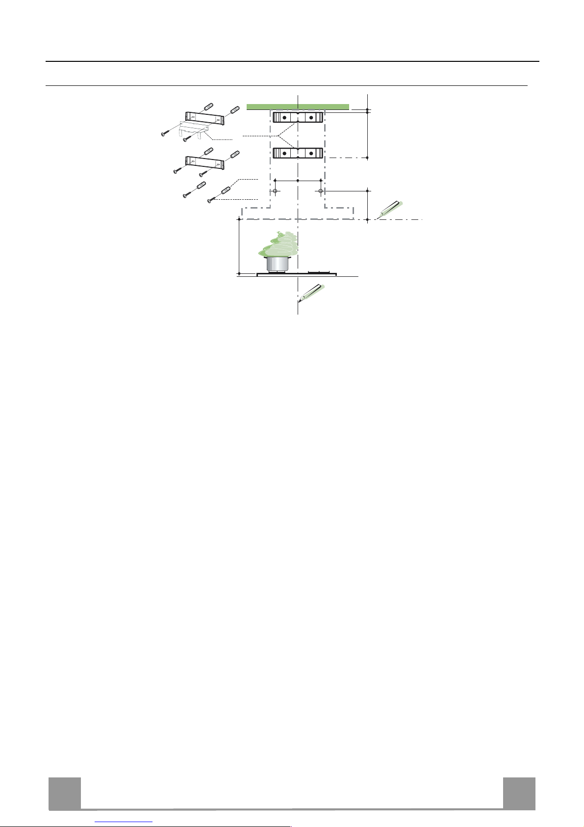
Wall drilling and bracket fixing
Wall marking:
• Draw a vertical line on the supporting wall up to the ceiling, or as high as practical, at the
centre of the area in which the hood will be installed.
• Draw a horizontal line at 650 mm above the hob.
• Place bracket 7.2.1 on the wall as shown about 1-2 mm from the ceiling or upper limit aligning the centr e (n otch) with the vertical reference line.
• Mark th e wall at the centres of the ho les in the bracket.
• Place bracket 7.2.1 on the wall as shown at X mm below the first bracket (X = height of the
upper chimney section supplied), aligning the centre (notch) with the vertical line.
• Mark th e wall at the centres of the ho les in the bracket.
• Mark a reference poi nt as indicated at 116 mm from the vertical reference line an d 320 mm
above the horizontal reference line.
• Repeat this operation on the other side.
• Drill ø 8 mm holes at all the centre points marked.
• Insert the wall plugs 11 in the holes.
• Fix the lower bracket 7.2.1 using the 12a screws (4,2 x 44,4) supplied.
• Fix the upper bracket 7.2.1 and the air outlet connection support 7.3 together using the 2
screws 12a (4,2 x 44,4) supplied.
• Insert th e two screws 12a (4,2 x 44,4) supplied in the hood body fixing holes, leaving a gap
of 5-6 mm between the wall and the head of the screw.
Page 6

EN
6
6
Mounting the hood body
• Before attaching the hood body, tighten the two screws Vr located on
the hood body mounti ng points.
• Hook the hood body on to the screws 12a.
• Fully tighten s upport screws 12a.
• Adjust screws Vr to level the hood body.
• If necessary, it is possible to fasten the hood to the wall using more
screws with wall plugs, which can be positioned from inside the hood
canopy.
12a
Vr
Connections
DUCTED VERSION AIR EXHAUST SYSTEM
When installing the ducted version, connect the hood to the
chimney using either a flexible or rigid pipe ø 150 or 120 mm,
the choice of which is left to the installer.
• To install a ø 120 mm air exhaust connection, insert the reducer flange 9 on the hood body outlet.
• Fix the pipe in position using sufficient pipe clamps (not supplied).
• Remove any activated charcoal filters.
9
ø 120ø 150
RECIRCULATION VERSION AIR OUTLET
• Insert the connection extensio n pieces laterall y 14.1 in conn ection 15.
• Insert the Co nnector 15 into t he Support bracket 7.3 and fix it
with a screw.
• Make sure that th e outlet of the extensi on pieces 14.1 is horizontally and vertically aligned with the chimney outlets.
• Connect the air outlet connection 15 to the hood body outlet
using either a flexible or rigid pipe ø 150 mm, the choice of
which is left to the installer.
• Ensure that the activated charcoal filters have been inserted.
ø 150
15
14.1
7.3
Page 7
EN
7
7
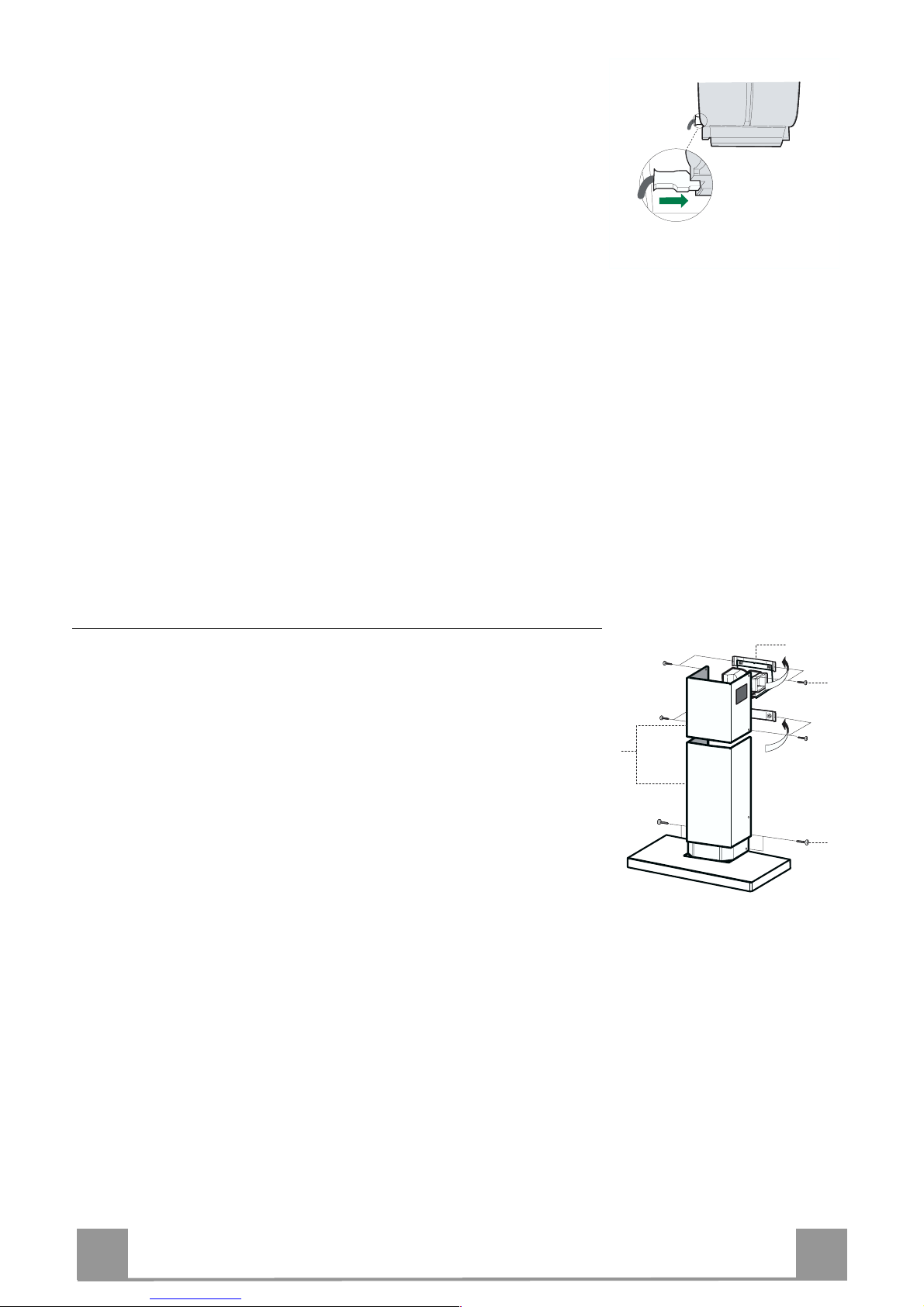
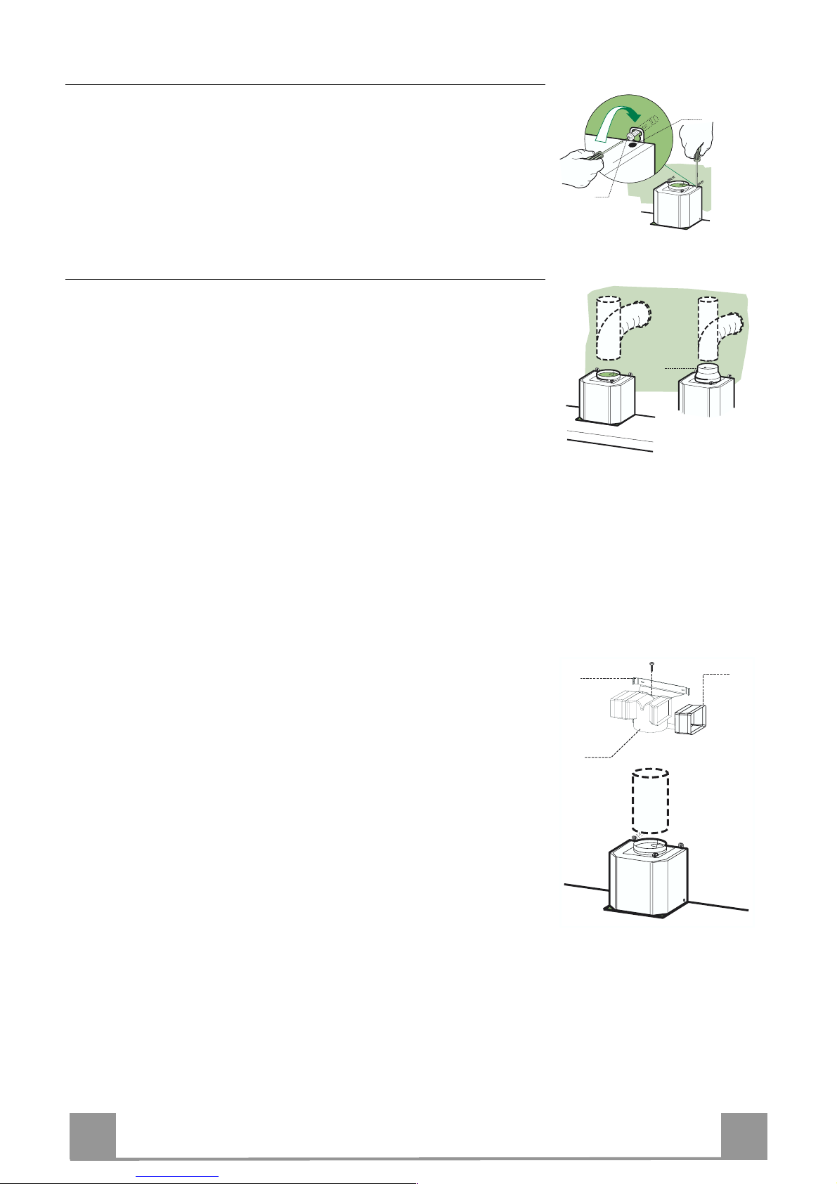
ELECTRICAL CONNECTION
• Connect the hood to the mains through a two-pole switch having a contact gap of at least 3 mm.
• Remove the grease filters (see paragraph Maintenance) being
sure that the connector of the feeding cable is correctly inserted
in the socket pl aced on the side of the fan.
Flue assembly
Upper exhaust fl ue
• Slightly widen the two sides of the upper flue and hook them
behind the b rackets 7.2.1, making sure that they are well
seated.
• Secure the sides to the brackets using the 4 screws 12c (2,9 x
9,5) supplied.
• Make sure t hat the outlet of the extensions pieces is aligned
with the chimney outlets.
Lower exhaust flue
• Slightly widen the two sides of the flue and hook them between the upp er flue and the wall, making sure that they are
well seated.
• Fix the lower part laterally to the hood body using the 2 screws
12c (2,9 x 9,5) supplied.
12c
2.1
2.2
2
7.2.1
12c
Page 8
EN
8
8
USE
B
A
D
C
E
G
F
I
H
L
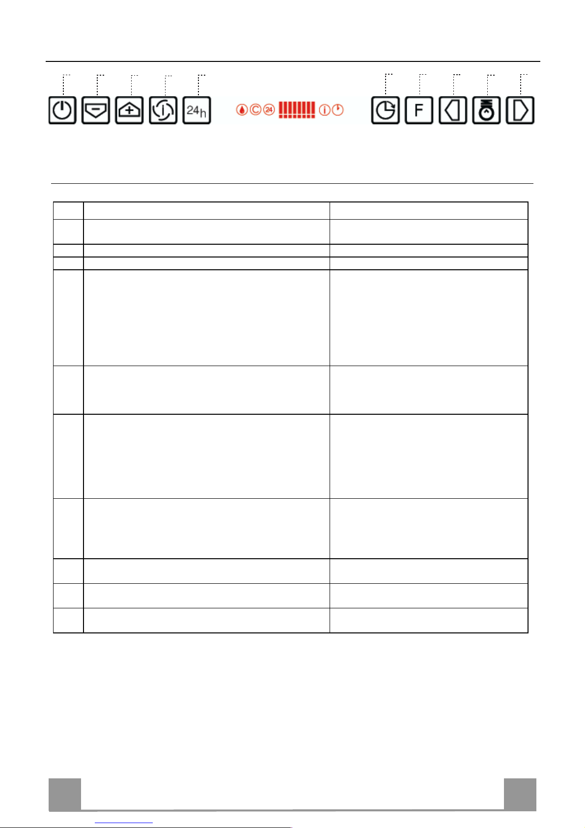
Control board
Key Function Display
A
Switches the extractor motor on and off at the latest
select ed speed
Indicates the selected speed .
B Decreases the suction speed. The number of lit LEDS d ecreases.
C Increases the suction speed. The number of lit LEDS increases.
D By pressing this key it is possible to start the inten-
sive speed from any previously selected speed except the Delay-function and 24H-function. This
speed has been timed at 10 minutes. After that time
the system activates automatically the latest selected
speed. This function is suitable for cooking conditions when vapours and smells are at the utmost emission.
I flashes and the LEDS are all lit.
By pressing the key the function is
stopped.
E By pressing this key it is possible to set up the motor
to a suction speed at 100 m
3
/h .
24 appears a nd the LEDS extinguis h one
by one.
By pressing the key the function is
stopped
F By pressing this key it is possible to set the delayed
shutdown of the motor and the lighting to 30 minutes. This function is suitable for a complete elimination of res idual cook ing odours. Functionin g only
when the mot or is on(n ot du rin g the 24H-fu nc ti on or
intensive function). By pressing the key the function
is stopped
A flashing clock-symbol appears.
By pressing the key the function is
stopped
G By pressing this key for about 2 seconds it is possi-
ble to reset the filter sa turation alarm
After 100 working hours a drop-symbol
appears. Metal grease filters have to be
washed.
After 200 working hours C appears.
Charcoal filters have to replaced.
H By pressing this key the intensity of the lighting
system can be decreased.
I Switches on/off th e lightin g system at th e maximu m
intensity.
L By pressing this key the intensity of the lighting
system can be increased.
Keyboard lock: i t is possible to jam the ke yboard when, for exa mple, cleaning th e glass. The
motor and lights are switched off.
By pressing the D-key (Intensive) for about 5 seconds the keyboard block can be activated or
deactivated. This function is confirmed by a Beep and by moving motor LEDS on display.
Page 9
EN
9
9
MAINTENANCE
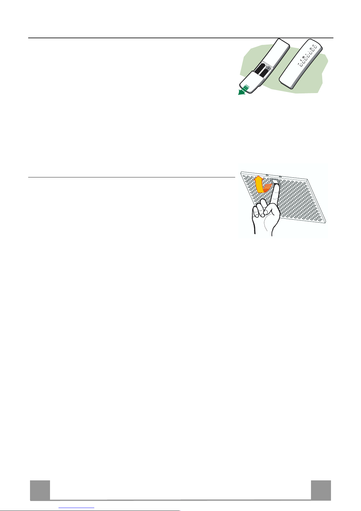
REMOTE CONTROL (OPTIONAL)
The appliance can be controlled using a remote control powered
by a 1.5 V carbon-zinc alkaline batteries of the standard LR03AAA type.
• Do not place the remote cont rol near to heat sources.
• Used batteries must be disposed of in the proper manner.
Metal grease filters
Metal filters can be washed also in a dish machine. They need to
be washed every time a drop-symbol appears in the display or at
least every two months. In case of very frequent use these have to
be washed even more often .
Alarm reset
• Press the G-key for at least 2 seconds.
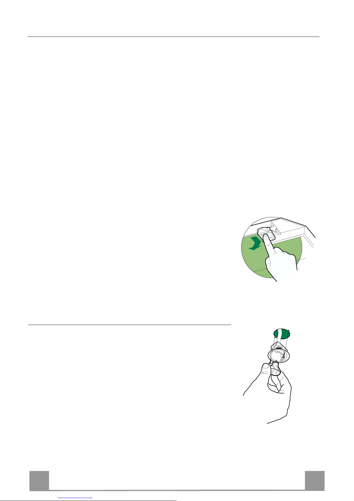
Cleaning
• Remove the filters one at a time holding them up with one
hand and pulling the handle downwards with the other hand at
the same time.
• Wash the filters. Pay attention not to bend them. Make sure
that filters are completely dry before putting them into their
seat. (a possible modification of the filter surface doesn’t influence its efficiency).
• Place the filters again into their seats and make sure that the
handle of the filter remains outside.
Page 10
EN
110
Charcoal filter (recycling version)
This filter cannot be washed or regenerated. It must be replaced when the C appears on the
display or at least once every 4 months. The filter saturation alarm has to be activated already
before.
Activation of the alarm signal
• In the recycling version hoods the filter saturation alarm must be activated during the installation or later.
• Switch off the hood and the lights.
• Press the E-key for about 5 seconds until the last two segments of the motor LEDS are lit on
the display.
• By releasing the E-key the clock icon starts to flash.
• Within 3 seconds press the D-key to activate/deactivate charco al filter saturation alarm.
• C-symbol lit - charcoal filter saturation alarm ACTIVATED.
• C-symbol unlit - charcoal filter saturation alarm DEACTIVATED.
SUBSTITUTION OF THE CHARCOAL FILTER
Alarm reset
• Switch off the motor and the lighting system.
• Press the G-key for at least 2 seconds.
Substitution of the filter
• Remove the metal grease filters.
• Remove the charcoal filter as indicated in the picture.
• Pl ace the filter again into its seat.
• Pl ace again the metal grease filters into their place.
Lighting
LIGHT REPLACEMENT
20 W halogen light.
• Remove the 2 screws fixing the Lighting support, and pull it
out of from the Hood.
• Extract the lamp from the Support.
• Replace with another of the same type, making sure that the
two pins are properly inserted in the lamp holder socket holes.
• Replace t he Support, fixing it in place with the two screws removed as above.
Page 11

IT 111
CONSIGLI E SUGGERIMENTI
Questo libretto di istruzioni per l'uso è previsto per più versioni dell'apparecchio.
Possibile che siano descritti singoli particolari della dotazione, che non riguardano il
Vostro apparecchio.
INSTALLAZIONE
• Il produ ttore declina qualsias i responsabilità per danni dovuti ad insta llazione non
corretta o non conforme alle regole dell’arte.
• La distanza minima di sicurezza tra il Piano di cottura e la Cappa deve essere di
650 mm.
• Verificare che la tensione di rete corrisponda a quella riportata nella targhetta posta
all’interno della Cappa.
• Per Apparecchi in Classe Ia accertarsi che l’impianto elettrico dome stico g arantis ca
un corretto sc arico a terra.
• Collegare la Cappa all’uscita dell’aria aspirata con tubazione di diametro pari o
superiore a 120 mm. Il percorso della tubazi one deve essere i l più breve possibi le.
• Non collegare la Cappa a condotti di scarico dei fumi prodotti da combustione (caldaie, caminett i , ecc.).
• Nel caso in cui nella stanza vengano utilizzati sia la Cappa che apparecchi non
azionati da energia elettrica (ad esempio apparecchi utilizzatori di gas), si deve
provvedere ad una aerazione sufficiente dell’ambiente. Se la cucina ne fosse
sprovvista, praticare un’apertura che comunichi con l’esterno, per garantire il richiamo d’aria pulita.
USO
• La Cappa è stata progettata esclusivamente per uso domestico, per abbattere gli
odori della cucina.
• Non fare mai uso i m pr oprio della Cappa.
• Non lasciare fiamme libere a forte intensità sotto la Cappa in funzione.
• Regolare sempre le fiamme in modo da evitare una evidente fuoriuscita laterale
delle stesse rispetto al fon do delle pentole.
• Controllare le friggitrici durante l’uso: l’olio surriscaldato potrebbe infiammarsi.
• Non preparare al imenti flambè sot to la cappa da cu cina; pericolo d'incendio.
• Questo apparecchio non deve essere utilizzato da persone (bambini inclusi) con
ridotte capacità psichiche, sensoriali o mentali, oppure da persone senza esperienza e conoscenza, a meno che non siano controllati o istruiti all’uso dell’apparecchio
da persone responsabili della loro sicurezza.
• I bambini devono essere supervisionati per assicurarsi che non giochino con
l’apparecc hio.
MANUTENZIONE
• Prima di procedere a qualsiasi operazione di manutenzione, disinserire la Cappa
togliendo la spina elettrica o spegnendo l’interruttore generale.
• Effettuare u na scrupolosa e tempestiva manu te nz io ne dei Filtri sec on do g li intervalli
consigliati.
• Per la pu lizia delle superfici d ella Cappa è sufficie nte utilizzare un pann o umido e
detersivo li quido neutro.
Il simbolo sul prodotto o sulla confezione indica che il prodotto non deve essere considerato
come un normale rifiuto domestico, ma deve essere portato nel punto di raccolta appropriato per il
riciclaggio di apparecchiature elettriche ed elettroniche. Provvedendo a smaltire questo prodotto in
modo appropriato, si contribuisce a evitare potenziali conseguenze negative per l’ambiente e per la
salute, che potrebbero derivare da uno smaltimento inadeguato del prodotto. Per informazioni più
dettagliate sul riciclaggio di questo prodotto, contattare l’ufficio comunale, il servizio locale di smaltimento rifiuti o il negozio in cui è st ato acquistato il prodotto.
650 mm min.
Page 12

IT 112
CARATTERISTICHE
Ingombro
650 min.
485
60
108 259
150
min. 670
max. 1000
540
260
300
898
6341126
81
Componenti
Rif. Q.tà Componenti di Prodotto
1 1 Corpo Cappa completo di: Comandi, Luce, Gruppo
Ventilatore, Filtri
2 1 Camino Telescopico formato da:
2.1 1 Camino Superiore
2.2 1 Camino Inferiore
9 1 Flangia di Riduzio ne ø 150-120 mm
14.1 2 Prolun ga Raccordo Uscita Aria
15 1 Raccordo Uscita Aria
Rif. Q.tà Componenti di Installazione
7.2.1 2 Staffe Fiss aggi o Cami no Su per i ore
7.3 1 Staffa Sostegno Raccordo
11 8 Tasselli
12a 8 Viti 4,2 x 44,4
12c 6 Viti 2,9 x 9,5
Q.tà Documentazione
1 Libretto Istruzioni
2.1
2.2
2
12c
12a
7.2.1 11
11
12a
1
9
7.3
14.1
15
Page 13
IT 113
INSTALLAZIONE
Foratura Parete e Fissaggio Staffe
7.3
11
12a
320
X
116
1÷2
116
650 min.
7.2.1
Tracciare sulla Parete:
• una linea Verticale fino al soffitto o al limite superiore, al centro della zona prevista per il
montaggio della Cappa;
• un a linea Orizzontale a: 65 0 mm min . sopra il Piano di Cottura.
• Appoggiare co me in di cato la Staffa 7.2.1 a 1-2 mm dal soffitto o dal limite superiore, allineando il suo centro (intagli) sulla linea Verticale di riferimento.
• Segnare i centri dei Fori della Staffa.
• Appoggiare co me indicat o la St affa 7.2.1 a X mm sotto la p rima staffa (X = altezza Ca mino
Superiore in dotazione), allineando il suo centro (intagli) sulla linea Verticale di riferimento.
• Segnare i centri dei Fori della Staffa.
• Segnare come indicato, un punto di riferimento a 116 mm dalla linea Verticale di riferimento, e 320 mm sopra la linea Orizzontale di riferimento.
• Ripetere questa operazione dalla parte opposta.
• Forare ø 8 mm i punti segnati.
• Inserire i tasselli 11 nei fori.
• Fissare la Staffa inferiore 7.2.1 utilizzando le Viti 12a (4,2 x 44,4 ) in dotazione.
• Fissare insieme la Staffa superiore 7.2.1 e la Staffa sostegno raccordo 7.3 utilizzando le 2
viti 12a (4,2 x 44,4) in dotazione.
• Avvitare 2 Viti 12a (4,2 x 44,4) in dotazione nei fori per il fissaggio del corpo Cappa, lasciando uno spazio di 5-6 mm fra la parete e la testa della vite.
Page 14
IT 114
Montaggio Corpo Cappa
• Prima di agganciare il Corpo Cappa, serrare le 2 Viti Vr situate sui
punti di aggancio del Corpo Cappa.
• Agganciare il Corpo Cappa alle Viti 12a.
• Serrare definitivamente le Viti 12a di supporto.
• Agire sulle Viti Vr per livellare il Corpo Cappa.
• Nel caso si ritenga opportuno è possibile assicurare la cappa al muro
per mezzo di altre viti con tassello, posizionabili dal
l’interno del corpo
cappa
.
12a
Vr
Connessioni
USCITA ARIA VERSIONE ASPIRANTE
Per installazione in Versione Aspirante collegare la Cappa alla
tubazione di uscita per mezzo di un tubo rigido o flessibile di
ø150 o 120 mm, la cui scelta è lasciata all'installatore.
• Per collegamento con tubo ø120 mm, inserire la Flangia di riduzione 9 sull’Uscita del Corpo Cappa.
• Fissare il tubo con adeguate fascette stringitubo. Il materiale
occorrente non è i n dotazione.
• Togliere eventuali Filtri Antiodore al Carbone attivo.
9
ø 120ø 150
USCITA ARIA VERSIONE FILTRANTE
• In serire lateralmente le P rolunghe Racco rdo 14.1 sul Raccordo
15.
• Inserire il Raccord o 15 nella Staffa di Sostegno 7.3 fissandolo
con una Vite.
• Assicurarsi che l’uscita delle Prolunghe Raccordo 14.1 risulti
in corrispondenza delle bocchette del Camino sia in orizzontale
che in verticale.
• Collegare i l Raccordo 15 all’Uscita del Corpo Cappa per mezzo di un tubo rigido o flessibile di ø150 mm, la cui scelta è lasciata all'installatore.
• Assicurarsi della presenza del Filtro Antiodore al Carbone attivo.
ø 150
15
14.1
7.3
Page 15

IT 115
CONNESSIONE ELETTRICA
• Collegare la Cappa all’Alimentazione di Rete interponendo un
Interruttore bipolare con apertura dei contatti di almeno 3 mm.
• Rimuovere i Filtri antigrasso (vedi par. “Manutenzione”) e assicurarsi che il connettore del Cavo di alimentazione sia correttamente inserito nella presa dell’Aspiratore
Montaggio Camino
Camino superiore
• Allargare leggermente le due falde laterali, agganciarle dietro
le Staffe 7.2.1 e richiuderle fino a battuta.
• Fissare lateralmente alle Staffe con 4 Viti 12c (2,9 x 9,5) in
dotazione.
• Assicurarsi che l’uscita delle Prolunghe Raccordo risulti in corrispondenza delle boc c he tte de l C amino.
Camino inferiore
• Allargare leggermente le due falde laterali del Camino, agganciarle tra il Camino superi ore e la parete e richiuderle fino a
battuta.
• Fissare lateralmente la parte inferiore al Corpo Cappa, con 2
Viti 12c (2,9 x 9,5) in dot azione.
12c
2.1
2.2
2
7.2.1
12c
Page 16

IT 116
USO
B
A
D
C
E
G
F
I
H
L
Quadro comandi
Tasto Funzione Display
A Accende e spegne il motore di aspirazione
all’ultima velocità utilizzata.
Visua l izza la velocità impostata.
B Dec r ementa la velocità di esercizio. Diminuiscono i segmenti accesi .
C Inc r ementa la velocità di esercizio. Aumenta no i segmenti accesi.
D Attiva la velocità intensiva da qualsiasi velo-
cità ad ecc ezione del Dela y e del 24H, ta le velocità è temporizzata a 10 minuti, al termine
del tempo il sistema ritorna alla velocità precedentemente impostata. Adatta a fronteggiare le
massime emissioni di fumi di cottura.
Lampeggia I e i segmenti sul Display sono tutti
accesi.
Si disattiva premendo il Tasto.
E Attiva il motore ad una velocità che consente
un’aspira zione di 100 m
3
/h per 10 minuti ogni
ora, terminati il motore si ferma.
Visualizza 24 e i segmenti sul Display da tutti
accesi si spengono uno al l a vo l ta cicl i cam e n te.
Si disattiva premendo il Tasto.
F Attiva lo spegnimento automatico ritardato di
30’. Adatto per completare l’eliminazione di
odori residui. Attivabile solo a motore acceso
ad una Velocità diversa da 24H e Intensiva, si
disattiva premendo il tasto o spegnendo il motore.
Visuali zza il simb olo di un Orologio che lampeggia.
Si disattiva premendo il Tasto.
G Effettua il Reset d ell’allarme sat urazion e Filtri
premendo il Tasto per circa 2 Secondi.
Dopo 100 ore di Funzionamento Visualizza il
simbolo Goccia per segnalare la saturazione
dei Filtri Metallici.
Dopo 200 ore di Funzionamento Visualizza C
per segnala re la s atur azion e dei Filtr i al Ca rbone Attivo.
H Decrementa l’intensità di Illuminazione ad
ogni pressione del Tasto in modo ciclico.
I Accende e spegne l’impianto di illuminazione
alla mas sima intensità.
L Inc rement a l’int ensit à di Illumi nazi one ad ogn i
pressione del Tasto in modo ciclico.
Comando Blocco Tastiera: è possibile bloccare la tastiera, ad esempio per effettuare l a pulizia
della superficie in Vetro, quando la Cappa ha il Motore e le Luci spente.
Premendo per circa 5 Secondi il tasto D (Intensiva) si può abilitare o disabilitare il Blocco Tastiera che è sempre confermato con un Beep e un’animazione sulla barra motore del display.
Page 17

IT 117
MANUTENZIONE
TELECOMANDO (OPZIONALE)
Questo apparecchi o può essere comandato per mezzo d i un telecomando, alimentato con pile alcaline zinco-carbone da 1,5 V del
tipo standard LR03-AAA.
• Non riporre il telecomando in prossimità di fonti di calore.
• Non disperdere le pile nell’ambiente, depositarle negli appositi
contenitori.
Filtri antigrasso metallici
Sono lavabili anche in lavastoviglie, e necessitano di essere lavati
quando sul display appare il simbolo Goccia o almeno ogni 2
mesi circa di utilizzo o più frequentemente, per un uso particolarmente intenso.
Reset del segnale di allarme
• P r emere il tast o G per almeno 2 Secondi.
Pulizia Filtri
• Togliere i Filtri uno alla volta,sostenendoli con una mano mentre con l’altra si tira la leva verso il basso.
• Lavare i Filtri evitando di piegarli, e lasciarli asciugare prima
di rimontarli. (Un ’eventuale cambiamento del colo re della superficie del filtro, che potrebbe verificarsi nel tempo, non pregiudica assolutamente l’efficienza dell o stesso.)
• Rimontarli facendo attenzione a mantenere la maniglia verso la
parte visibile estern a.
Page 18

IT 118
Filtri antiodore al Carbone attivo (Versione Filtrante)
Non è lavabile e non è rigenerabile, va sostituito quando sul display appare il simbolo C o almeno ogni 4 mesi. La segnalazione di Allarme va preventivamente attivata.
Attivazione del segnale di al larme
• Nelle Cappe in Versione Filtrante, la segnalazione di Allarme saturazione Filtri va attivata al
momento dell’installazione o su ccessivamente.
• Spegnere le Luci e il Motore di aspi razi one.
• Premere il tasto E per circa 5 Sec . fino all’accension e degli ultimi due segmenti e di tutta la
linea puntinata della barra Motore sul Display.
• Rilasciare il tasto E, l’icona “Orologio” inizia a lampeggiare.
• Entro 3 secondi premere il Tasto D per abilitazione / disabilitazione Filtri C.A.
• Accensione del simbolo C Allarme saturazione Filtro C.A. ATTIVATO
• Spegnimento del simbolo C Allarme saturazione Filtro C.A. DISATTIVATO
SOSTITUZIONE FILTRO ANTIODORE AL CARBONE ATTIVO
Reset del segnale di allarme
• Spegnere le Luci e il Motore di aspi razi one.
• P r emere il tast o G per almeno 2 Secondi.
Sostituzione Filtro
• Togliere i Filtri antigrasso metallici.
• Rimuovere il Filtro antiodore al Carbone attivo saturo, come
indicato i n figura.
• Montare il nuovo Filtro agganciandolo nella sua sede.
• Rimontare i Filtri antigrasso metallici.
Illuminazione
SOSTITUZIONE LAMPADE
Lampade alogene da 20 W.
• Togliere le due viti che fissano il Supporto illuminazione e sfilarlo dalla Cappa.
• Estrarre la Lampada dal Supporto.
• Sostituirla con una nuova di uguali caratteristiche, facendo attenzione di inserire correttamente i due spinotti nella sede del
Supporto.
• Rimontare il Supporto fissandola con le due Viti precedentemente tolte.
Page 19

FR
119
CONSEILS ET SUGGESTIONS
La présente notice d'emploi vaut pour plusieurs versions de l'appareil. Elle peut contenir des
descriptions d'accessoires ne figurant pas dans votre appareil.
INSTALLATION
• Le fabricant décline toute responsabilité en cas de dommage dû à une installation non correc te ou non conforme aux règ les de l’art.
• L a dis ta nc e mi nim al e d e séc uri té entr e l e pl an de c uis son et l a h ott e doi t être d e 650 mm au
moins.
• Vérifier que la tens io n du s ecteur correspond à la valeur qui figure sur la plaquette apposée à
l’intérieur de la hotte.
• Pour les Appareils appartenant à la Ière Classe, veiller à ce que la mise à la terre de
l’installation él ectr ique dome stique ai t été effe ctuée confo rmémen t aux nor mes en vigueur .
• Connecter la hotte à la sort ie d’air aspiré à l’aide d’une tu yauterie d’un diamè tre égal ou supérieur à 120 mm. Le parcours de la tuyauterie doit être le plus court possible.
• Eviter de connecter la hotte à des conduites d’évacuation de fumées issues d’une combustion tel q ue (Chaudière, ch eminée, etc…).
• Si vous utilisez des appareils qui ne fonctionnent pas à l’électricité dans la pièce ou est installée la hotte (par exemple: des appareils fonctionnant au gaz), vous devez prévoir une aération suffisante du milieu. Si la cuisine en est dépourvue, pratiquez une ouverture qui communique avec l’exté r ieur pour garantir l’infiltration de l’air pur.
UTILISATION
• La hotte a été conçue excl usivement pour l’usage domestique, dans le but d’éliminer les
odeurs de la cuisine.
• Ne jamais utiliser abusivement la hotte.
• Ne pas laisser les flammes libres à forte intensité quand la hotte est en service.
• Toujours r égler les fl ammes de mani ère à éviter toute sorti e latérale de c es dernières par
rapport au fond des marmites.
• Contrôler les friteuses lors de l’utilisation car l’huile surchauffée pou rrait s’enf lammer.
• Ne pas préparer d’aliments fla mbés sous la hotte de cuis ine : risque d’in cendie
• Cet appareil ne doit pas être utilisé par des personnes (y compris les enfants) ayant des
capaci tés psyc hiques, sensor ielles o u mental es rédui tes, ni p ar des p ersonne s n’ay ant pas
l’expérience et la connaissance de ce type d’appareils, à moins d'être sous le contrôle et la
formation de personnes responsables de leur sécurité.
• Les enfants doivent être surveillés pour s'assurer qu'ils ne jouen t pas avec l'appa reil.
ENTRETIEN
• Avant d e procé der à tout e opérati on d’e ntretie n, retirer la hotte en retira nt la fich e ou en actionnant l’interr upteu r généra l.
• Effectuer un entretien scrupuleux et en temps dû des Filtres, à la cadence conseillée.
• Pour le nettoyage des surfaces de la hotte, il suffit d’utiliser un chiffon humide et détersif
liquide neutre.
Le symbole sur le produit ou son emballage indique que ce produit ne peut être traité comme déchet
ménager. Il doit plutôt être remis au point de ramassage concerné, se chargeant du recyclage du matériel
électrique et électronique. En vous assurant que ce produit est éliminé correctement, vous favorisez la
prévention des conséquences négatives pour l’environnement et la santé humaine qui, sinon, seraient le
résultat d’un traitement inapproprié des déchets de ce produit. Pour obtenir plus de détails sur le recyclage
de ce produit, veuillez prendre contact avec le bureau municipal de votre région, votre service d’élimination
des déchets ménagers ou le magasin où vous a vez a ch e t é l e produi t .
650 mm min.
Page 20

FR
220
CARACTERISTIQUES
Encombrement
650 min.
485
60
108 259
150
min. 670
max. 1000
540
260
300
898
6341126
81
Composants
Réf. Q.té Composants de Produit
1 1 Co rps Hotte équip é de:Commande s, Lumière, Gr oupe
Ventilateur,Filtres
2 1 Cheminée Télescopique formée de :
2.1 1 Cheminée Supérieure
2.2 1 Cheminée Inférieure
9 1 Flasque de Réduction ø 150-1 2 0 mm
14.1 2 Rallonge Raccord Sortie Air
15 1 Raccord Sortie Air
Réf. Q.té Composants pour l ’installation
7.2.1 2 Brides Fixation Cheminée Supérieure
7.3 1 Bride Support Raccord
11 8 Chevilles
12a 8 Vis 4,2 x 44,4
12c 6 Vis 2,9 x 9,5
Q.té Documentation
1 Manuel d’instructions
2.1
2.2
2
12c
12a
7.2.1 11
11
12a
1
9
7.3
14.1
15
Page 21

FR
221
7.3
11
12a
320
X
116
1÷2
116
650 min.
7.2.1
INSTALLATION
Perçage Paroi et Fixation Brides
Tracer sur la paroi:
• une ligne verticale allant jusqu’au plafond ou à la limite supérieure, au centre de la zone
prévue pour le montage de la hotte;
• une ligne horizontale à 650 mm min. au-dessus du plan de cuisson.
• Poser comme indiqué une bride 7.2.1 sur la paroi à 1-2 mm du plafond ou de la limite supérieure, en alignant son centre (découpes) sur la ligne verticale de repère.
• Marquer les centres des trous rainurés de la bride.
• Poser comme indiqué la bride 7.2.1 à X mm sous la première bride (X = hauteur cheminée
supérieure fournie), en alignant son centre (déco upes) sur la ligne verticale de rep ère.
• Marquer les centres des trous rainurés de la bride.
• Marquer comme indiqué, un point de référence à 116 mm de la ligne verticale de repère, et
320 mm au-dessus de la ligne horizontale de repère.
• Répéter cette opération sur le cô té opposé.
• Percer de ø 8 mm tous les points marqués.
• Insérer les chevilles 11 dans les trous.
• Fixer la bride inférieure 7.2.1 en utilisant les vis 12a (4,2 x 44,4) fournies.
• Fixer ensemble la bride supérieure 7.2.1 et le support 7.3 en utilisant les vis 12a (4,2 x 44,4)
fournies.
• Visser les 2 vis 12a (4,2 x 44,4) fournies dans les trous de fixation du corps hotte, en laissant
un le espace de 5-6 mm entre le mur et la tête de la vis
Page 22

FR
222
Montage Corps Hotte
• Avant d’accrocher le corps hotte, serrer les deux vis Vr situées sur les
points d’accrochage du corps hotte.
• Accrocher le corps hotte aux vis 12a prévues à cet effet.
• Serrer définitivement les vis 12a de support.
• Agir sur les vis Vr pour niveler le corps hotte.
• Si cela est jugé nécessaire, il est possible de fixer la hotte au mur au
moyen de chevilles et vis supplémentaires qu’il faudra placer de
l’intérie ur du co r ps de la hotte.
12a
Vr
Branchements
SORTIE AIR VERSION ASPIRANTE
En cas d’installation en version aspirante, brancher la hotte à la
tuyauterie de sortie via un tube rigide ou flexible de ø 150 ou 120
mm, au choix de l’installateur.
• En cas de branchement avec un tube de ø120 mm, insérer le
flasque de réduction 9 sur la sortie du corps de la hotte.
• Fixer le tube par des colliers appropriés. Le matériau nécessaire n’est pas fourni.
• Retirer les éventuels filtres anti-odeur au charbon actif.
9
ø 120ø 150
SORTIE AIR VERSION FILTRANTE
• Insérer latéralement les rallonges raccord 14.1 sur le raccord
15.
• Placer le raccord 15 dans l’étrier de soutien 7.3 en le fixant
avec une vis.
• S’assurer que la sort ie des rallonges racco rd 14.1 se trouve au
niveau des bouches de la cheminée aussi bien en horizontal
qu’en vertical .
• Brancher l e raccord 15 à la sortie du corps de la hotte avec un
tube rigide ou flexible de ø 150 mm, selon le choix de
l’installateur.
• S’assurer de la présence des filtres anti-odeur au charbon actif.
ø 150
15
14.1
7.3
Page 23

FR
223
BRANCHEMENT ELECTRIQUE
• Branch er la hotte sur le secteur en interposant un interrupteur
bipolaire avec o uverture des contacts d’au moins 3 mm.
• Enlever les filtres à graisse (voir § "Entretien") et s'assurer que
le connecteu r du câb le d 'alimentat io n so it bi en bran ch é dans la
prise du diffu seur.
Montage Cheminée
Cheminée supérieure
• Elargir légèrement les deux bords latériaux, et les accrocher
derrières les brides 7.2.1 ; refermer
jusqu’à la butée.
• Fixer latéralement aux brides à l’aide des 4 vis
12c fournies.
• S’assurer q ue la sortie des rallonges raccord se trouve au niveau des bouches de la cheminée.
Cheminée inférieure
• Elargir légèrement les deux bords latériaux de la Cheminée et
les accrocher entre la Cheminée supérieure et la paroi; refermer
jusqu’à la butée.
• Fixer latéralement la partie inférieure au corps
hotte, à l’aide des deux 2 vis 12c fournies.
12c
2.1
2.2
2
7.2.1
12c
Page 24

FR
224
UTILISATION
B
A
D
C
E
G
F
I
H
L
Tableau des commandes
Touche Fonction Afficheur
A Allume et éteint le moteur d’aspiration à la der-
nière vitesse utilisée
La vitesse choisie s’affiche.
B La vitesse de service diminue. Les segments allumés diminuent.
C La vitesse de service augmente. Les segments allumés augmentent.
D Active la vitesse intensive à partir de n’importe
quelle vitesse, à l’exception des fonctions Retard
et 24H. Cette vitesse est programmée pour durer
10 minutes, après quoi le système retourne à la
vitesse ré glée au préala ble. Apte à fa ire fac e à un e
quantité maximale de fumées de cuisson.
I clignote et les segments affichés sont
tous allumés.
Appuyer sur la touche pour désactiver.
E Active le moteur à une vitesse permettant une aspi-
ration de 100 m
3
/h pendant 10 minutes chaque
heure, puis le moteur s’arrête.
24 s’affiche et les segments affichés qui
étaient tous allumés s’éteignent un à un
de manière cyclique.
Appuyer sur la touche pour désactiver.
F Active l’arrêt automatique retardé de 30 minutes.
Sert à éliminer complètement toute odeur résiduelle. S’active quand le moteur allumé à une
vitesse différente de 24H et Intensive ; appuyer sur
la touche ou éteindre le moteur pour désactiver
cette fonction.
Le symbole d’une horloge qui clignote
s’affiche.
Appuyer sur la touche pour désactiver.
G Rétablit l’alarme de saturation des filtres en ap-
puyant sur la touche pendant environ 2 secondes.
Le symbole Goutte s’affiche après 100
heures de service pour signaler la saturation des fi ltres métalliques.
C s’affiche après 200 heures de service
pour signaler la saturation des filtres au
charbon actif.
H L’intensité de l’éclairage diminue de façon cycli-
que chaque fois que l’on appuie sur la touche.
I Allume et ét eint l’éclairage à intensité maxima le.
L L’intensité de l’éclairage augmente de façon cycli-
que chaque fois que l’on appuie sur la touche.
Commande de blocage du Clavier : il est possible de bloquer le clavier, par exemple pour effectuer le nettoyage des surfaces en verre quand le moteur et l’éclairage de la hotte sont
éteints.
Appuyer sur la touche D (intensive) pendant env. 5 secondes pour activer ou désactiver le blocage du clavier ; cette fonction est toujours confirmée par un bip sonore et une animation qui
s’affiche sur la barre du moteur .
Page 25

FR
225
ENTRETIEN
TELECOMMANDE (FOURNIE SUR DEMANDE)
Il est possible de commander cet appareil au moyen d’une télécommande, alimentée avec des piles alcalines zinc-charbon 1,5 V
du type standard LR03-AAA.
• Ne pas ranger la télécommande à proximité de sources de chaleur.
• Ne pas jeter les piles; il faut les déposer dans les récipients de
récolte spéciale ment prévus à cet effet.
Filtres à graisse métalliques
Ils sont lavables même en lave-vaisselle et doivent être lavés
chaque fois qu e le symbo le Goutte s’affiche ou au moins tou s les
2 mois environ, voire plus souvent, en cas d’utilisation particulièrement intensive.
Rétablissement du signal d’alarme
• Appuyer sur la touche G pendant au moins 2 secondes.
Nettoyage des filtres
• Enlevez les filtres l’un après l’autre en les soutenant avec une
main et en tirant en même temps la poignée vers le bas avec
l’autre main.
• Laver les filtres en évitant de les plier, et les faire sécher avant
de les remonter. (Tout ch ange me nt de co ul eur su r la surface du
filtre, susceptible de se produire avec le temps, ne nuit en rien
à l’efficacité de ce dernier.)
• Remonter les filtres en faisant attention de tenir la poignée vers
la partie externe visible.
Page 26

FR
226
Filtres anti-odeur au charbon actif (version filtrante)
Il ne peut être ni lavé ni récupéré, il faut le changer quand le symbole C s’affiche ou au moins
tous les 4 mois. Il faut tout d’abord activer le signal d’alarme.
Activation du signal d’alarme
• Pour les hottes en version filtrante, l’alarme indiquant la saturation des filtres doit être activée au moment de l’installation ou ultérieurement.
• Éteindre les lumières et le moteur d’aspiration.
• Appuyer sur la touche E pendant 5 sec. environ, jusqu’à ce que les deux derniers segments
et toute la ligne en pointillés de la barre Moteur s’allument sur l’afficheur.
• Relâcher la touche E, l’icône “Horloge” commencera à clignoter.
• Appuyer sur la touche D dans les 3 sec ondes qui s uivent pour activer/désactiver les filtres
au C.A.
• Le symbole C s’allume : alarme de saturation du filtre au C.A. ACTIVÉE
• Le symbole C s'éteint : alarme de saturation du filtre au C.A. DÉSACTIVÉE
REMPLACEMENT DU FILTRE ANTI-ODEUR AU CHARBON ACTIF
Rétablissement du signal d’alarme
• Éteindre les lumières et le moteur d’aspiration.
• Appuyer sur la touche G pendant au moins 2 secondes.
Remplacement du Filtre
• Retirer les Filtres à graisse métalliques.
• Suivre les indications (A) pour retirer le filtre anti-odeur au
charbon actif saturé.
• Mettre le nouveau Filtre en l’accrochan t bien en place.
• Remonter les Filtres à graisse métalliques.
Eclairage
REMPLACEMENT LAMPES
Lampe halogène de 20 W.
• Retirer les 2 V is qui fixent le Support éclairage et ô ter ce dernier de la Hotte.
• Extraire la Lampe du Support.
• Re mplacer par u ne nouvelle lampe possédant les mêmes caractéristiques, en veillant à ce que les deux fiches soient correctement insérées dans le logement de la Douille.
• Remonter le Support en le fixant à l’aide des deux Vis précédemment retirées.
Page 27

DE
227
EMPFEHLUNGEN UND HINWEISE
Diese Gebrauchsanleitung gilt für mehrere Geräte-Ausführungen. Es ist möglich, dass
einzelne Ausstattungsmerkmale beschrieben sind, die nicht auf Ihr Gerät zutreffen.
MONTAGE
• Das Gerät darf nur vom Fachpersonal angeschlossen werden.
• Der Hers teller ha ftet nic ht für Sch äden, di e auf eine fehler hafte un d unsach gemäß e Montage zurückzuführen sind.
• Der minimal e Sicherh eitsabst and zwisch en Kochmul de und Hau be muss 650 m m betragen.
• Prüfen, ob die Netzspannung m it dem Wert auf dem im Haub eninneren ang ebrachten Schild übereinstimmt.
• B ei Ger ät en der Klass e I i s t si c her z ustellen, dass die elektrische Anla ge des Wohnhauses
über eine vorschriftsmäßige Erdung verfügt.
• Das Anschlussrohr der Haube zur Luftaustrittsöffnung sollte möglicherweise einen
Durchmesser von 150 mm aufweisen. Der Rohrverlauf muss so kurz wie möglich sein.
• Die Haube darf an keine Entlüftungsschächte angeschlossen werden, in die Verbrennungsgase (Heizkessel, Kamine usw.) geleitet werden.
• Werden im Raum außer der Dunstabzugshaube andere, nicht elektrisch betriebene (z.B.
gasbetri eb e ne) Geräte verwendet, m us s für eine ausreichende Belüftun g gesorgt werden.
Sollte di e Küc he di esbez üglic h nich t en tsprec hen, i st an einer A usse nwa nd ei ne Öff nung
anzubri ng en , di e Fri s c hluftzufuhr gewährlei s tet .
BEDIENUNG
• Die Dunstabz ugshau be ist aussc hließlic h zum Eins atz im priva ten Haush alt und zur B eseitigung v on Küchengerüch en vorgesehen.
• Bei unsachgemäßer Benutzung wird keine Haftung übernommen.
Achtung! Große Flammen bei eingeschalteter Haube niemals unbedeckt lassen.
• Die Intensivität der Flamme ist so zu regulieren, dass sie den Topfboden nicht überragt.
Achtung! Frittiergeräte müssen während des Gebrauchs stets beaufsichtigt werden: Überhitztes Öl kann sich entzünden.
• Keine flambierten Speisen unter der Abzugshaube zubereiten: Brandgefahr.
• Dieses Gerät darf nicht von Personen, auch Kindern, mit verminderten psychischen,
sensoris chen und gei stigern F ähigkei ten, oder von Person en ohne Erfa hrung un d Kenntnisse benutzt werden, sofern sie nicht von für ihre Sicherheit verantwortlichen Personen
beaufsichtigt und beim Gebrauch des Geräts angeleitet werden.
• Kinder d ürf en s ich nic ht unbe aufs ic hti gt i n der Nähe des Ger äts auf halt en un d au f k ein en
Fall mit dem Gerät spielen.
WARTUNG
• Bevor Wartungsarbeiten durc hgeführt werden, muss die Stromzufuhr zur Haube unterbrochen wer den, indem der Stecker gezoge n od er der Ha u pts c h al t er ab ges chaltet wird.
• Bei der Filterwartung müssen die vom Hersteller empfohlenen Zeiträume zum Austauschen der Filter genauestens eingehalten werden.
• Zur Rei nigu ng der Hau benfläc hen Wir em pfehl en ei n f eucht es Tuc h un d ein m ildes Flüssigreinigungsmittel.
• Bitte keine Reinigungsmittel mit Scheuermittel verwenden. Die Oberfläche wird damit
verkratzt.
Das Symbol auf dem Produkt oder seiner Verpackung weist darauf hin, dass dieses Produkt nicht als
normaler Haushaltsabfall zu behandeln ist, sondern an einem Sammelpunkt für das Recycling von elektrischen und elektronischen Geräten abgegeben werden muss. Durch Ihren Beitrag zum korrekten Entsorgen
dieses Produkts schützen Sie die Umwelt und die Gesundheit Ihrer Mitmenschen. Umwelt und Gesundheit
werden durch falsches Entsorgen gefährdet. Weitere Informationen über das Recycling dieses Produkts
erhalten Sie von Ihrem Rathaus, I hrer M ül l abfuhr oder dem Geschäft, in dem Sie das Produkt gekauft haben.
650 mm min.
Page 28

DE
228
CHARAKTERISTIKEN
Platzbedarf
650 min.
485
60
108 259
150
min. 670
max. 1000
540
260
300
898
6341126
81
Komponenten
Pos. St. Produktkomponenten
1 1 Haubenkörper mit Schaltern, Beleuchtung, Gebläse-
gruppe, Filter
2 1 Teleskopkamin bestehend aus:
2.1 1 oberer Kaminteil
2.2 1 unterer Kaminteil
9 1 Reduzierflans ch ø 150-120 mm
14.1 2 Verlängerung Luftaustritt-Anschlussstück
15 1 Luftaustritt-Anschlussstück
Pos. St. Montagekomponenten
7.2.1 2 Befestigungsbügel oberer Kaminteil
7.3 1 Bügel für Anschlusshalter
11 8 Dübel
12a 8 Schrauben 4,2 x 44,4
12c 6 Schrauben 2,9 x 9,5
St. Dokumentation
1 Bedienungsanleitung
2.1
2.2
2
12c
12a
7.2.1 11
11
12a
1
9
7.3
14.1
15
Page 29

DE
229
7.3
11
12a
320
X
116
1÷2
116
650 min.
7.2.1
MONTAGE
Bohren der Befestigungslöcher und Fixieren der Befestigungsbügel
Achtung: Bitte beachten Sie bei der Montage das Gewicht der kompletten Haube. Die Tragfä-
higkeit der Decke oder alternativ der Trägerplatte für diese Zugbelastung muss vor der Montage geprüft und gegebenenfalls durch die Anbringung von geeigneten Befestigungs- oder
Stabilisierungselementen hergestellt werden. Kann eine hinreichende Tragfähigkeit nicht sichergestellt werden, ist von einer Montage abzusehen.
Nachstehende Linien an die Wand zeichnen:
• Eine vertikale Linie bis zur Decke oder oberen Begrenzung, und zwar in der Mitte des Bereiches,in dem die Haube montiert werden soll;
• Eine horizontale Linie: mit einem minimalen Abstand von 650 mm zur Kochfläche.
• Einen Bügel 7.2.1 zirka 1-2 mm un ter der Decke oder oberen Begrenzun g an die Wand le-
gen und seinen Mittelpunkt (Einschnitte) auf die vertikale Bezugslinie ausrichten.
• Die Mitte der beiden Bügellöcher an der Wand markieren.
• Den zweiten Bügel 7.2.1 an die Wand legen, wobei ein Abstand X mm vom oberen Bügel
einzuhalten ist (X = Höhe des jeweiligen oberen Kaminteils); den Mittelpunkt (Einschnitte)
auf die vertikale Bezugslinie ausrichten .
• Die Mitte der Bügellöcher an der Wand markieren.
• Wie beschrieben einen Bezugspunkt 116 mm von der vertikalen Bezugslinie und 320 mm
oberhalb der horizontalen Bezugslinie kennzeichnen.
• Gleichermaßen an der gegenüberliegenden Seite vorgehen.
• Mit einem Bohrer ø 8 mm die markierten Punkte bohren.
• Die Dübel 11 in die Bohrungen einfügen.
• Den unteren Bügel mit den mitgelieferten Schrauben 12a (4,2 x 44,4) fixieren.
• Den Bügel für Anschlusshalter mit den 2 mitgelieferten Schrauben 12a (4,2 x 44,4) auf den
oberen Bügel 7.2.1 befestigen.
• 2 der mitgelieferten Schrauben 12a(4,2 x 44,4)bei den Befestigungslöchern des Haubenkörpers einschrauben, wobei zwischen Wand und Schraubenkopf ein Freiraum von 5-6 mm zu
belassen ist.
Page 30

DE
330
Montage des Haubenkörpers
• Bevor der Haubenkörper eingehakt wird, die 2 Schrauben Vr bei den
Haubenkörper-Anhakpunkten festziehen.
• Den Haube nkö r per bei den Sc hr aube n 12a einhäng e n.
• Die Halteschrauben 12a definitiv festziehen.
• Den Haubenkörper mit Hilfe der Schrauben Vr ausrichten.
• Die Haube kann bei Bedarf mit Hilfe weiterer Schrauben und Dübel
von innen an der Wand gesichert werden.
12a
Vr
Anschluss der Abluftversion
Bei Abluftbetrieb kann die Haube vom Installateur wahlweise
mittels Rohr oder Schlauch (ø 150 oder 120 mm) an die Außenrohrleitung angeschlossen werden.
• Bei Verwendung eines Anschlussrohres ø 120 den Reduzierflansch 9 am Haubenaustritt anbringen.
• Das Rohr mit geeigneten Rohrschellen fixieren. Das hierzu
erforderliche Material wird nicht mitgeliefert.
• Eventuell vorhandene Aktivkohlefilter entnehmen.
Achtung! Alle Q uerschnittänderungen oder Richt ungsän-
derung en des A bluftka nals r eduzier en die Leist ung der H aube.
9
ø 120ø 150
Anschluss der Umluftversion
• Di e Verlängeru n gen 14.1 beim Anschluss 15 seitlich einfügen.
• Den Anschluss 15 am Haltebügel 7.3 einsetzen und mit einer
Schraube fixieren.
• Überprü fen, ob die Verlän gerungen 14.1 mit den entsprechenden Kaminstutzen sowohl horizontal wie auch vertikal übereinstimmen.
• Vom Installateur wahlweise mittels Rohr oder Schlauch (ø 150
mm), den Anschluss 15 am Haubenaustritt anbringen.
• Kontrollieren, ob der Aktivkohle-Geruchsfilter montiert ist.
ø 150
15
14.1
7.3
Page 31

DE
331
Elektroanschluss
Vor der Installation die Netzspannung durch herausdrehen der
Sicherung oder ausschalten des Hauptschalters stromlos machen.
• Bei Anschluss der Haube an das Stromnetz muss ein
zweipoliger Schalter mit einem Öffnungsweg von
mindestens 3 mm zwischengeschaltet werden.
• Entfernen Sie die Fettfilter (s. Abschnitt „Wartung“) und
versichern Sie sich, daß die Kabelverbindung in die Steckdose des Gebläses einwandfrei eingesteckt wird.
Achtung: Das Gerät nur an die Netzspannung die im Typen-
schild angegeben ist ansc hließen.
Kaminmontage
Oberer Kaminteil
• Die beiden seitlichen Schenkel leicht auseinanderbiegen, hinter
den Bügeln 7.2.1 einhängen und bis zu m Anschl ag wieder
schließen.
• Bei den Bügeln 7.2.1 mit Hilfe der 4 mitgelieferten Schrauben
12c fixieren.
• Überprüfen, ob die Verlängerungen mit den entsprechenden
Kaminstutzen übereinstimmen.
Unterer Kaminteil
• Die beiden seitlichen Schenkel des Kaminteils leicht auseinander biegen, zwischen dem oberen Kaminteil und der Wand
einhängen und bis zum Anschlag wieder schließen.
• Den unteren Teil seitlich am Haubenkörper mit 2 der mitgelieferten Schrauben 12c fixieren.
12c
2.1
2.2
2
7.2.1
12c
Page 32

DE
332
BEDIENUNG
B
A
D
C
E
G
F
I
H
L
Bedienfeld
Taste Funktion Display
A Schaltet den Gebläsemotor in der zuletzt ver-
wendeten Gebläsestufe ein und aus.
Zeigt die eingestellte Gebläsestufe an.
B Verringert die laufende Gebläsestufe. Die leuchtenden Segmente nehmen ab.
C Steigert die laufende Gebläsestufe. Die leuchtenden Segmente nehmen zu.
D Aktiviert die Intensivstufe bei jeder Geschwin-
digkeit, mit Ausnahme der Funktionen Delay
und 24H. Die Intensivstufe ist auf 10 Minuten
begrenzt. Danach kehrt das System zur zuvor
eingest ellten Gebläs estufe zurüc k. Zum Beseitigen sehr starker Küchendünste geeign et.
I blinkt und alle Segmente auf dem Display
leuchten.
Lässt sich durch Drücken der Taste ausschalten.
E Schaltet den Motor auf einer Gebläsestufe ein,
die pro Stunde ein zehnminütiges Absaugen
von 100 m3/h erlaubt. Danach schaltet sich der
Motor aus.
Zeigt 24 an und alle auf dem Display angezeigten Segmente erlöschen allmählich nacheinander.
Lässt sich durch Drücken der Taste ausschalten.
F Aktiviert das automatische Abschalten nach 30
Minuten. Zum Beseitigen von verbliebenen
Küchendünsten geeignet. Lässt sich nur bei
eingeschaltetem Motor und nicht bei Intensivstufe oder 24-Stunden-Funktion aktivieren.
Lässt sich durch Drücken der Taste oder durch
Ausschalten des Motors deaktivieren.
Zeigt das Symbol einer blinkenden Uhr an.
Lässt sich durch Drücken der Taste ausschalten.
G Durch ca. 2 Sekunden langes Drücken der Tas-
te wird die Filtersättigungsanzeige rückge-
stellt.
Nach 100 Betriebsstunden zeigt das Symbol
Tropfen die Sättigung der Metallfilter an.
Nach 200 Betriebsstunden zeigt C die Sättigung der Aktivkohlefilter an.
H Verringert die Intensität der Beleuchtung zyk-
lisch mit jedem Drücken der Taste.
I Schaltet die Beleuchtungsanlage auf höchster
Intensitätsstufe ein und aus.
L Steigert die Intensität der Beleuchtung zyklisch
mit jedem Drücken der Taste.
Steuerbefehl Tastatur sperre: Die Tastatur lässt sich, z. B. zur Reinigun g der Scheiben , sperren,
wenn Motor und Beleuchtung der Haube ausgeschaltet sind.
Zum Aktivieren oder Deaktivieren der Tastatursperre die Taste D (Intensivstufe) ca. 5 Sekunden lang drücken. Der Vorgang wird immer durch einen Piepton und die Motorbalkenanzeige
auf dem Display bestätigt.
Page 33

DE
333
WARTUNG
FERNBEDIENUNG (OPTIO N)
Dieses Gerät kann mit einer Fernbedienung gesteuert werden,
welche mit alkalischen Zink-Kohle-Batterien 1,5 V des Standardtyps LR03-AAA versorgt wird.
• Die Fernbedienung nicht in die Nähe von Hitzequellen legen.
• Batterien müssen vorschriftsmäßig en t s orgt werden.
Metallfettfilter
Die Filter können im Geschirrspüler gereinigt werden und sollten
gereinigt werden, wenn das Symbol Tropfen auf dem Display
erscheint bzw. mindestens ca. alle 2 Monate oder bei sehr intensivem Einsatz auch häufiger.
Rückstellen der Sättigungsanzeige
• Die Taste G mindestens 2 Sekunden lang drücken.
Filterreinigung
• Einen Filter nach dem anderen entfernen. Halten Sie den Filter
mit einer Hand fest und ziehen Sie den Griff mit der anderen
Hand gleichzeitig nach unten.
• Die Filter waschen, darauf achten, sie nicht zu verbiegen und
vor der Remontage trocknen lassen. (Eine eventuell im Lauf
der Zeit auftretende Verfärbung der Filteroberfläche hat
keinerlei Einfluss auf die Wirksamkeit des Filters.)
• Bei der Remontage darauf achten, dass sich der Griff an der
sichtbaren Außenseite befindet.
Page 34

DE
334
Aktivkohle-Geruchsfilter (Umluftversion)
Nicht waschbar und nicht regenerierbar. Ersetzen, wenn das Symbol C auf dem Display erscheint bzw. mindestens alle 4 Monate. Das Alarmsignal ist vorher zu aktivieren.
Aktivierung des Alarmsig nals
• Bei Hauben in Umluftversion muss die Aktivierung der Filtersättigungsanzeige bei der Installation oder dana c h erf olg e n.
• Die Beleuchtung und den Gebläsemotor abschalten.
• Die Taste E ca. 5 Se kunden lang gedrückt halten, bis die beiden letzten Segmente und die
ganze gepunktete Linie der Motoranzeige auf dem Display aufleuchten.
• Die Taste E loslassen. Das Symbol “Uhr” beginnt zu blinken.
• In nerhal b von 3 Se kunde n die Taste D zur Aktivierung / Deaktivierung der Aktivkohlefilter drücken.
• Bei Aufleuchten von Symbol C ist die Aktivkohlefilter-Sättigungsanzeige AKTIVIERT.
• Bei Erlöschen von Symbol C ist die Aktivkohlefilter-Sättigungsanzeige DEAKTIVIERT.
ERSETZEN DES AKTIVKOHLE-GERUCHSFILTERS
Rückstellen der Sättigungsanzeige
• Die Beleuchtung und den Gebläsemotor abschalten.
• Die Taste G mindestens 2 Sekunden lang drücken.
Ersetzen des Filters
• Die Metallfettfilter ausbauen.
• Den gesättigten Aktivkohle-Geruchsfilter wie in der Zeichnung
dargestellt entfernen.
• Den neuen Filter an seinem Platz montieren.
• Die Metallfettfilter wieder montieren.
Beleuchtung
AUSWECHSELN DER LAMPEN
Halogenlampe 20 W
• Vor dem Auswechseln der Lampen, die beiden Schrauben der
Lampenhalterung loesen und die Lampenhalterung aus der
Dunstabzugshaube ziehen.
• Die Lampe aus d er Halterung nehmen.
• Die Lampe durch eine gleichwertige ersetzen und bei der Remontage darauf achten, daß die beiden Steckerstifte vorschriftsmäßig in die Lampenfassung eingeführt werden.
• Die Lampenhalterung wieder montieren, indem die beiden zuvor entfernten Schrauben wieder angezogen werden.
Page 35

TR
335
TAVSIYELER VE ÖNERILER
Bu kullanma tal imat ι birden fazla c ihaz model i içi n geç erl idi r.
Cihazιnιza uymayan bazι donanιm özellikleri tarif edilmiş olabilir.
MONTAJ
• Yalnιş veya e ksik mo nta jda n doğan he rha ngi b ir zara rιn sorumluluğu üreticiye ait
değildir.
• Davlu mbaz ile pi şirici cihazιn ocak kιsmι arasιndaki minimum güvenlik mesafesi
650 mm.dir.
• Besleme voltajιnιn, davlumbaz içerisine yerleştirilen bilgi etiketinde belirtilenle
aynι olup olmadιğιnι kont rol edin.
• Sιnιf I elektrikli aletleri için, güç kaynağιnιn yeterli topraklamayι sağlayιp
sağlamadιğιnι kontrol edin. Minimum 120 mm çapιnda bir boru yoluyla
davlumbazι çιkιş bacasιna bağlayιn. Baca bağlantιsι mümkün oldu- ğunca kιsa
olmalιdιr.
• Davlumbaz borusunu yanιcι duman taşιyan baca de l iğine (buhar kazanι, şömine,
vb.) bağlamayιn.
• Davlumbazιn elektrikle çalιşmayan aletlerle (örneğin; gazlι cihazlar) bağιntιlι ola-
rak kullanιlmamasι halinde çιkιş gazιnιn geri tepmesini önlemek amacιyla odada
yeterli bir havalandιrma sağlanmalιdιr. Temiz hava girişin i temin e tmek için mut-
fakta doğruda n dιşar ιya açιlan bir açιklιk bulunmal ιdιr.
KULLANIM
• Davlumbaz mutfaktaki kokularιn emilmesi amacιyla evlerde kullanιm için
tasarlanmιştιr.Ticari v e endüs t riy el amaç lar içi n kull anmay ιnιz.
• Davlumbazι tasarlandιğι amaçlarιn dιşιnda kesinlik le k ullanmay ιnιz.
• Davlumbaz çalιşιrken altιnda kesinlikl e yüksek çιplak ateş bιrakmayιn.
• Alev yoğunluğunu doğrudan tencerenin altιnda kalacak şekilde ayarlayιn,
kenarlarιnι sarmadιğιndan emin olun.
• Yağda kιzartma tavalarιnι kullanιrken sürekli olarak takip edin: fazla ιsιnan yağ
tutuşabilir.
• Kapağın altında kıvı lcı mdan k açı nı n, y angın r i ski
• Bu alet, güvenliklerinden sorumlu kişiler tarafından kontrol edilmedikleri veya
eğitilmedikleri sürece; fiziksel, duyumsal ve zihinsel kapasitesinde kısıtlama olan
(çocuklar dahil) veya aleti kullanma tecrübesi ve bilgisi olmayan kişiler tarafından
kullanılamaz.
• Bebeklerin, al etl e oy namadık l arı ndan em in ol mak i ç in kont rol edil meli ger eki r.
BAKIM
• Herhangi bir bakιm işlemini gerçekleştirmeden önce davlumbazι kapatιn veya
fişini çιkarιn.
• Filtreleri bel irt ilen zamanl ar da t emiz ley i n ve / v ey a değiştirin.
• Cihazι neml i bi r bez v e nötr bir sιvι deterjan k ull anarak t emiz leyi n.
Ürün vey a pak eti üz erin deki sem bolü , bu ür ünü n norm al bi r evs el a tık olar ak görülm em esi
ve bu tip elektr ikli v eya elektr onik ci hazlar ın atıl dığı dönüşümlü toplam a nokt aları na t erk edil mesi
gerektiğine işaret ede r. Bu ür ü nü ger ekt i ği gibi el i mi ne et m e kural l arı na uy ar s anız çev re v e ins an
sağlığı üzerinde ki olumsuz etk ilerini ber taraf etmey e katkı sağlamış olursunuz. Bu ürünün geri
dönüşüm koşulları hakkında daha ayrıntılı bilgi için hudutları içinde bulunduğunuz belediyenin
ilgili diaresine, atık yoket me servisine veya ürünün sat ıcısına danışınız.
650 mm min.
Page 36

TR
336
ÖZELLIKLER
Boyutlar
650 min.
485
60
108 259
150
min. 670
max. 1000
540
260
300
898
6341126
81
Parçalar
Ref. Adet Ürünün parçaları
1 1 Şunlardan oluşan davlumbaz gövdesi: Kumandalar,
Lamba, Fan grubu, Filt reler
2 1 Şunlardan oluşan teleskopik baca:
2.1 1 Üst baca
2.2 1 Alt baca
9 1 Redüksiyon Flanşı ø 150-120 mm
14.1 2 Hava Çıkışı Uzatma Rakoru
15 1 Hava Çıkışı Rakoru
Ref. Adet Montaj Parçaları
7.2.1 2 Üst Baca Tesbit Braketleri
7.3 1 Rakor Destek Braketi
11 8 Dübeller
12a 8 Vidalar 4,2 x 44,4
12c 6 Vidalar 2,9 x 9,5
Adet Belgeler
1 Talimat Kılavuzu
2.1
2.2
2
12c
12a
7.2.1 11
11
12a
1
9
7.3
14.1
15
Page 37

TR
337
7.3
11
12a
320
X
116
1÷2
116
650 min.
7.2.1
MONTAJ
Duvarın Delinmesi ve Braketlerin Sabitlenmesi
Duvara şunları çiziniz:
• Tavana yada üst sınıra kadar uzunan Dikey bir çizgi: Davlumbazın monte edileceği yerin
tam merkezinden geçmelidir;
• Tezgâh (setüstü ocak) yüzeyinden 650 mm mesafeden geçen bir Yatay çizgi.
• Gösterildiği gibi Braketi 7.2.1 tavandan 1-2 mesafeye dayayınız ve bunun merkezini (çen-
tik) Dikey referans çizgisine hizalayınız.
• Braketin deliklerinin ortasından işaret koyunuz.
• Gösterildiği gibi Braketi 7.2.1 ilk braketin altına ve bundan X mesafeye dayayınız (X = Üst
Bacanın boyu) ve b unun merkezini (çentik) Dikey refer ans çizgisine hizalayınız.
• Braketin deliklerinin ortasından işaret koyunuz.
• Gösterildiği gibi Dikey referans çizgisinden 116 mm mesafeye, Yatay referans çizgisinin de
320 mm üzerine gelecek şekilde bir referans deliği işaretleyiniz.
• Bu işlemi diğer taraftan da tekrar ediniz.
• İşaretlenen yerlere ø 8 mm çapında delikler açınız.
• Dübelleri (11) deliklere yerleştiriniz.
• Cihaz donanımında verilen vidaları 12a (4,2 x 44,4 ) kullanarak alt Braketi 7.2.1
sabitleyiniz.
• Üs Braket 7.2.1 ile rakor destek Braketini 7.3 cihaz donanımında verilen 2 adet vidayı 12a
(4,2 x 44,4 ) kullanarak birlikte sabitleyiniz.
• Davlumbaz gövdesinin sabitlenmesi için, açılan deliklere donanımdaki 2 adet vidayı 12a
(4,2 x 44,4) takıp, sıkınız ve vidanın kafası ile duvar arasında 5-6 mm’lik bir mesajfe bırakınız.
Page 38

TR
338
Davlumbaz Gövdesi Montajı
• Davlumbaz Gövdesini kancalara takmadadan önce gövde üzerindeki
kancalama nokt alarında bulunan 2 adet v idayı Vr sıkınız.
• Davlumbaz Gövdesini vidalara 12a takınız .
• Destek vidalarını 12a nihai olarak sıkın ız.
• Vr vidalarına müdahale ederek Davlumbaz Gövdesi seviyesini hizalayınız.
• Gerekli görülmesi halinde, gövdesinin iç kısmına yerleştirilebilecek iki
adet dübel l i v ida il e, bacanın duvara te spit edilmesi mümk ün dür .
12a
Vr
Bağlantılar
ASPİRATÖRLÜ MODEL HAVA ÇIKIŞI
Aspiratörlü modelin montajı için, davl umbaz, montörü n seçeceği
150 yada 120 mm çapında sert veya esnek bir boru ile çıkış kanalına bağlanmalıdır.
• ø120 mm çapında boru ile bağlantı için, redüksiyon flanşını (9)
davlumbaz gövdesi çıkışına yerleştiriniz.
• Boruyu uygun kelepçelerle sıkarak sabitleyiniz. Bu malzeme
davlumbaz donanımıyla birlikte verilmemiştir.
• Varsa aktif karbonlu koku alma filtrelerini çıkarınız.
9
ø 120ø 150
FİLTRE VERSİ YONUNDA BAĞLANTILAR
• Rakor Uzantılarını 14.1 diğer rakora takınız 15.
• Soketi 15 destek mesnedine 7.3 yerleştirin ve bir vida ile
sabitleyin.
• Rakor uzantıları çıkışının 14.1 hem dikey hem yatay planda
baca ağızlarına denk gelmesine dikkat ediniz.
• Rakoru 15 montörün seçeceği sert yada esnek 150 mm çapında
bir boru ile davlumbaz gövd esi Çıkışına bağlayınız.
• Aktif karbonlu koku filtresinin mevcut olduğundan emin olu-
nuz.
ø 150
15
14.1
7.3
Page 39

TR
339
ELEKTRİK BAĞLANTISI
• Davlumbazı şebeke cere yanına bağlarken aray temas aralığı en
az 3 mm olan çift kutuplu bir elektrik anahtarı koyunuz.
• Yağ tutucu filtreleri çıkarınız (bakınız "Bakım" paragrafı) ve
besleme kablosu soketinin aspiratör prizine iyice takılmış olduğundan emin olunuz.
Bacanın montajı
Üst baca
• İki yan kenarı hafifçe açınız, bunları braketlerin 7.2.1 arkasına
geçiriniz ve tam dayanana kadar tekrar kapatınız.
• Cihaz donanımında verilen 4 adet vidayla 12c (2,9 x 9,5) yan
taraflarından brake tle re sabitley iniz .
• Rakor uzantılarının çıkışının baca ağızlarına denk gelmesine
dikkat ediniz.
Alt baca
• Bacanın iki yan kenarını hafifçe açınız, Üst baca ile duvar arasına geçirip tam dayanana kadar kapatınız.
• Cihaz donanımında verilen 2 adet vidayla 12c (2,9 x 9,5) alt
tarafını davlumbaz gövdesine sabitleyiniz.
12c
2.1
2.2
2
7.2.1
12c
Page 40

TR
440
KULLANIM
B
A
D
C
E
G
F
I
H
L
Kumanda Tablosu
Tuş İşlev Ekran
A Emme motorunu son kullanılan hızda açar ve
kapatır.
Ayarlanan hızı görüntüler.
B Çalışma hızını düşürür. Açık segmanları azaltırlar.
C Çalışma hızını yükseltir. Açık segmanları arttırırlar.
D Delay ve 24H haricinde, herhangi bir hızdan
yoğun hıza geçer, bu hız 10 dakika zaman ayarlıdır , bu süre sonunda sistem daha önced en
ayarlanan hıza geri döner. Pişirme anındaki
dumanın fazla yayılmasını engellemeye uygundur.
I yanar ve Ekranda tüm segmanlar açılır.
Tuşa basılarak devreden çıkartılır.
E Motoru, her saa tte bir 10 dakik a 100 m3/h emiş
hızında aktive eder, bitiminde motor durur.
24 görüntülenir ve Ekranda açık olan tüm
segmanlar belirli aralıklarla birer birer sönerler.
Tuşa basılarak devreden çıkartılır.
F
30’ geciktirmeli otomatik kapanışı akti ve eder.
Kalan yemek kokularının yok edilme işleminin
tamamlanmasına uygundur. Sadece motorun
24H veya Yoğun hızdan farklı bir hızda çalış-
masında aktive edilebilir, tuşa basılarak veya
motor durdurularak devreden çıkartılır.
Yanar bir Saa t sembolü görüntü lenir.
Tuşa basılarak devreden çıkartılır.
G Tuşa yaklaşık 2 saniye basılarak Filtre doy-
gunluk alar m ı Resetlenir.
100 Çalışma saati sonunda, Metal Filtrelerin
doygunluğunu belirten Damla sembolü görüntülenir.
200 Çalışma saati sonunda, Aktif Karbonlu
Filtrelerin doygunluğunu belirten C görüntülenir.
H Devir modunda her Tuş basımında aydınlatma
yoğunluğunu d üşürür.
I Aydınlatma tesisatını maksimum yoğunlukta
açar ve kapatır.
L Devir modunda her Tuş basımında aydınlatma
yoğunluğunu yükseltir.
Klavye Bloke Etme Kumandası: Klavyeyi bloke etmek mümkündür, örneğin Davlumbazın
Motoru ve Işıkları kapalıyken, Cam yüzeylerin temizliğinde.
Klavye Bloke Etme ö zell iği, D tuşuna yaklaşık 5 saniye basarak, her zaman bir Bip sesiyle ve
ekranın motor çubuğunda bir animasyonla teyitle geçerli veya geçersiz kılınabilir.
Page 41

TR
441
BAKIM
TELEKUMANDA (OPSİYONEL)
Bu cihaza bir telekumanda ile de komut verilebilir; bu kumanda
1,5 Voltluk çinko-karbonlu LR03-AAA tipi standart alkalin pillerle çalışır.
• Telekumandayı ısı kaynakları yakınında bırakmaynız.
• Pilleri çevreye atmayınız, bunlara ayrılmış çöp toplama kaplarına atınız.
Yağlanmaya karşı metal filtreler
Bulaşık makinasında yıkanabilirler ve yaklaşık her 2 aylık kullanım sonrasında veya özellikle yoğun kullanım durumunda daha
sıklıkla yıkanmaları gerekir.
Alarm sinyalinin resetlenmesi (sıfırlanması)
• G tuşuna en az 2 saniye basınız.
Filtrelerin Temizle nmesi
• Filtreleri teker teker çıkarınız ve bunu yaparken kolu aşağı
doğru çektiğiniz sırada diğer elinizle filtreleri tutunuz.
• Filtreleri kıvrılmamalarına dikkat ederek sökünüz ve yıkayınız,
tekrar takmadan önce kurumaya bırakınız. (Filtre yüzeyinde
zamanla görülebi lecek olası renk değişikliği, kesinlikle etkinliğine zarar vermez)
• Tutamağın dış görünür tarafta olduğuna dikkat ederek filtreleri
tekrar monte ediniz.
Page 42

TR
442
Aktif Karbonlu Kokuya Karşı Filtreler (Filtre Edici Versiyon)
Yıkanamaz, yeniden kullanılamaz, ekranda C sembolü görüntülendiğinde veya en az 4 ayda
bir değiştirilir. Alarm sinyali önceden aktive olur.
Alarm sinyali nin aktive edilmesi
• Filtre edici versiyon Davlumbazlarda, Filtreler doygunluk Alarm sinyali, kurulum anında
veya devamında aktive olur.
• Işıkları ve emme Motorunu kapatınız.
• E tuşuna, son i ki segman ın ve Ekran ü zerind e Mo tor çub uğun un tüm iğneli hattının açılışına
kadar yaklaşık 5 saniye basınız.
• E tuşundan parmağınızı çekiniz, “Saat” simgesi yanmaya başlar.
• 3 saniye içinde, C A filtrelerini geçerli / geçersiz kılmak için D tuşuna bas ı nız .
• C sembolünün yanması, CA Filtre doygunluk Alarmı AKTİVE EDİLMİŞ.
• C sembolünün sönmesi, CA Filtre doygunluk Alarmı AKTİVE EDİLMEMİŞ.
AKTİF KARBONLU KOKUYA KARŞI FİLTRENİN DEĞİŞTİRİLMESİ
Alarm sinyalinin resetlenmesi (sıfırlanması)
• Işıkları ve emme Motorunu kapatınız.
• G tuşuna en az 2 saniye basınız.
Filtrenin Değiştirilmesi
• Yağlanmaya karşı metal filtreler
• Aktif Karbonlu kokuya karşı doymuş filtreyi resimde gösterildiği şekilde çıkartınız.
• Yeni Filtreyi yuvasına takarak monte ediniz.
• Yağlanmaya karşı metal filtreler
Aydınlatma
AMPUL DEĞİŞTİRME
20 W halojen ampuller
• Lamba Destek parçasını sabitleyen iki vidayı söküp, parçayı
Davlumbazdan çı karınız.
• Ampulü Destek parçasından çıkarınız.
• Aynı özelliklere sahip bir yenisi ile değiştiriniz ve iki küçük
(iğne) fişinin Destek parçası içindeki yuvalarına iyi oturduğun-
dan emin olunuz.
• Destek parçasını tekrar yerine takıp daha önce sökülen vidaları
ile sabitleyiniz.
Page 43

Page 44

436004365_ver3
Franke S.p.a.
Via Pignolini,2
37019 Peschi era del Garda (VR)
www.franke.it
 Loading...