

Page 1

Istruzioni per l’uso e l’installazione
Cappa
Instructions for use and installation
Cooker Hood
Mode d’emploi et installation
Hotte de Cuisine
Bedienungsanleitung und Einrichtung
Dunstabzugshaube
Kullan
ım ve montaj talimatları
Davlumbaz
FCL 602
FCL 902
IT
GB
FR
DE
TR
Page 2

IT
2
2
Libretto di Istruzioni
INDICE
CONSIGLI E SUGGERIMENTI ..............................................................................................................................................7
CARATTERISTICHE..............................................................................................................................................................8
INSTALLAZIONE....................................................................................................................................................................9
USO......................................................................................................................................................................................12
MANUTENZIONE.................................................................................................................................................................13
Page 3

EN
3
3
Instructions Manual
INDEX
RECOMMENDATIONS AND SUGGESTIONS....................................................................................................................14
CHARACTERISTICS............................................................................................................................................................15
INSTALLATION ....................................................................................................................................................................16
USE.......................................................................................................................................................................................19
MAINTENANCE....................................................................................................................................................................20
Page 4

FR
4
4
Manuel d’Instructions
SOMMAIRE
CONSEILS ET SUGGESTIONS ..........................................................................................................................................21
CARACTERISTIQUES.........................................................................................................................................................22
INSTALLATION ....................................................................................................................................................................23
UTILISATION........................................................................................................................................................................26
ENTRETIEN..........................................................................................................................................................................27
Page 5

DE
5
5
Bedienungsanleitung
INHALTSVERZEICHNIS
EMPFEHLUNGEN UND HINWEISE....................................................................................................................................28
CHARAKTERISTIKEN..........................................................................................................................................................29
MONTAGE............................................................................................................................................................................30
BEDIENUNG.........................................................................................................................................................................33
WARTUNG............................................................................................................................................................................34
Page 6

TR
6
6
Kullanim Kilavuku
IÇERIKLER
TAVSIYELER VE ÖNERILER ..............................................................................................................................................35
ÖZELLIKLER........................................................................................................................................................................36
MONTAJ...............................................................................................................................................................................37
KULLANIM............................................................................................................................................................................40
BAKIM...................................................................................................................................................................................41
Page 7

IT
7
7
CONSIGLI E SUGGERIMENTI
INSTALLAZIONE
• Il produttore declina qualsiasi responsabilità per danni dovuti
ad installazione non corretta o non conforme alle regole
dell’arte.
• La distanza minima di sicurezza tra il Piano di cottura e la
Cappa deve essere di 650 mm.
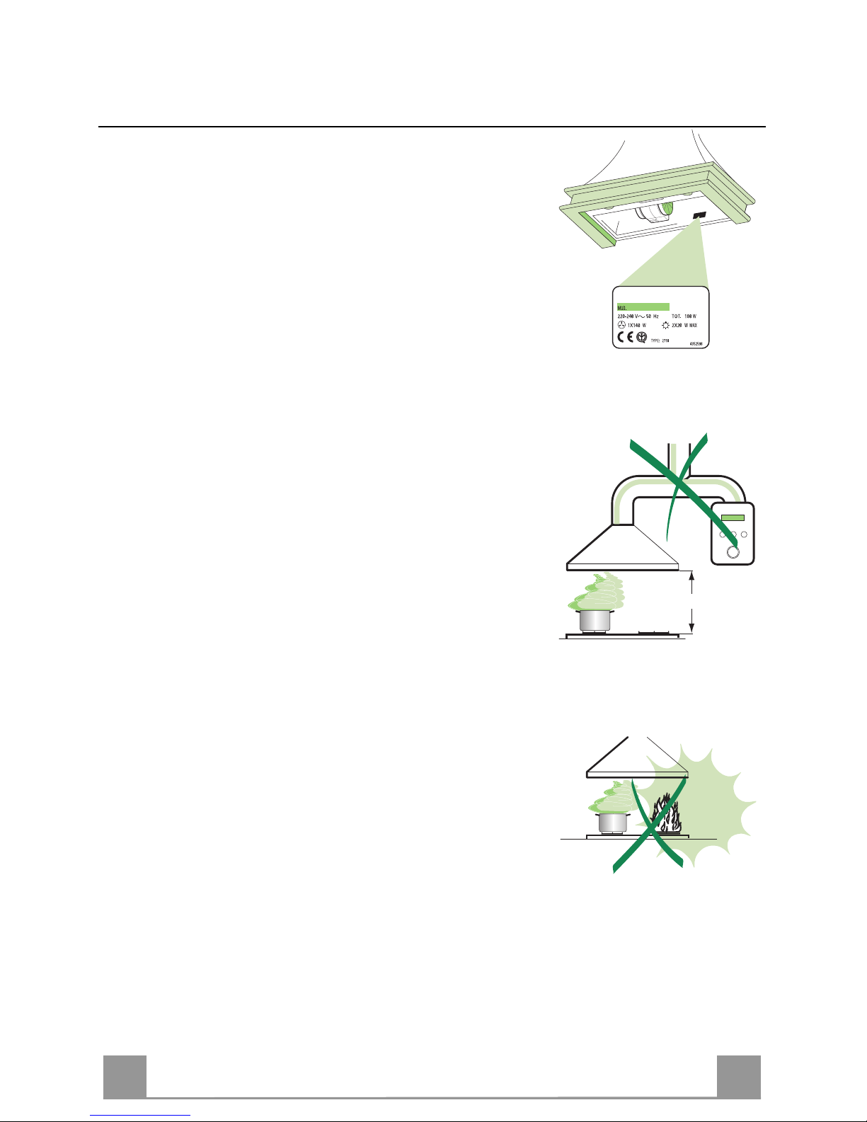
• Verificare che la tensione di rete corrisponda a quella riportata
nella targhetta posta all’interno della Cappa.
• Per Apparecchi in Classe Ia accertarsi che l’impianto elettrico
domestico garantisca un corretto scarico a terra.
• Collegare la Cappa all’uscita dell’aria aspirata con tubazione di
diametro pari o superiore a 120 mm. Il percorso della tubazione deve essere il più breve possibile.
• Non collegare la Cappa a condotti di scarico dei fumi prodotti
da combustione (caldaie, caminetti, ecc.).
• Nel caso in cui nella stanza vengano utilizzati sia la Cappa che
apparecchi non azionati da energia elettrica (ad esempio apparecchi utilizzatori di gas), si deve provvedere ad una aerazione
sufficiente dell’ambiente. Se la cucina ne fosse sprovvista, praticare un’apertura che comunichi con l’esterno, per garantire il
richiamo d’aria pulita.
USO
• La Cappa è stata progettata esclusivamente per uso domestico,
per abbattere gli odori della cucina.
• Non fare mai uso improprio della Cappa.
• Non lasciare fiamme libere a forte intensità sotto la Cappa in
funzione.
• Regolare sempre le fiamme in modo da evitare una evidente
fuoriuscita laterale delle stesse rispetto al fondo delle pentole.
• Controllare le friggitrici durante l’uso: l’olio surriscaldato potrebbe infiammarsi.
• La Cappa non deve essere utilizzata da bambini o persone non
abilitate all’uso corretto.
MANUTENZIONE
• Prima di procedere a qualsiasi operazione di manutenzione,
disinserire la Cappa togliendo la spina elettrica o spegnendo
l’interruttore generale.
• Effettuare una scrupolosa e tempestiva manutenzione dei Filtri
secondo gli intervalli consigliati.
• Per la pulizia delle superfici della Cappa è sufficiente utilizzare
un panno umido e detersivo liquido neutro.
650 mm min.
Page 8
IT
8
8
CARATTERISTICHE
Ingombro
110145
598 / 898 /1198
500
145145
500
260
212
275
200
100
Componenti
Rif. Q.tà Component i di Prodotto
1 1 Corpo Cappa completo di: Comandi, Luce, Gruppo
Ventilatore, Filtri
2 1 Camino
8 1 Griglia direzionata ø125 mm
9 1 Flangia di riduzione ø 150-120 mm
10 1 Cornice Mensola (opzionale)
20 1 Profilo in legno (opzionale)
Rif. Q.tà Componenti di Installazione
7.2 1 Staffa fissaggio camino
11 2 Tasselli
11a 2 Tasselli SB 12/10
12a 2 Viti 4,2 x 44,4
12e 2 Viti 2,9 x 12,7
12m 6 Viti 2,9 x 18
12n 7 Vit i 3,5 x 16
Q.tà Documentazione
1 Libretto Istruzioni
1
2
12m
20
7.2
12n
10
11
12a
12e
8
9
11a
Page 9

IT
9
9
INSTALLAZIONE
Foratura Parete e Fissaggio Staffe
Dimensione ca pp a Quota X
60 cm 128 mm
90 cm 150 mm
120 cm 175 mm
Tracciare sulla Parete:
• una linea Verticale fino al soffitto o al limite superiore, al centro della zona prevista per il
montaggio della Cappa;
• una linea Orizzontale a: 650 mm min. sopra il Piano di Cottura;
• Segnare come indicato, un punto di riferimento a 395 mm sopra la linea orizzontale di riferimento, e a X mm (dove X = vedi tabella sul disegno) sulla destra della linea verticale di riferimento.
• Ripetere questa operazione dalla parte opposta, verificandone il livellamento.
• Forare ø 12 mm i punti segnati.
• Inserire i tasselli con vite e staffa 11a nei fori, avvitare.
• Appoggiare come indicato la staffa 7.2 a 750 mm sopra la linea orizzontale, allinneando il
suo centro (intagli) sulla linea verticale di riferimento.
• Segnare i centri dei fori della staffa.
• Forare ø 8 mm i punti segnati.
• Inserire i tasselli 11 nei fori.
• Fissare la staffa, utilizzando le viti 12a (4,2 x 44,4) in dotazione.
11a
650 min.
750
7.2
XX
395
Page 10
IT 110
Montaggio Camino
• Allargare leggermente le due falde laterali del camino, agganciarle dietro la Staffa 7.2 e richiuderle fino
a battuta.
• Inserire il Profilo in legno 20 fra il Corpo Cappa e il
Camino.
• Fissare dal sopra la parte inferiore del Camino e il
Profilo al Corpo Cappa con 6 Viti 12m (2,9 x 18) in
dotazione.
7.212m
20
Montaggio Corpo Cappa
• Regolare le due viti Vr, delle staffe 11a, ad inizio
corsa.
• Agganciare il corpo cappa alle 2 staffe 11a.
• Togliere i Filtri uno alla volta, spingendoli verso la
parte posteriore del gruppo e tirando contemporaneamente verso il basso.
• Dall’interno del corpo cappa agire sulle Viti Vr per
livellare il Corpo Cappa.
Vr
Connessioni
USCITA ARIA VERSIONE ASPIRANTE
Per installazione in Versione Aspirante collegare la
Cappa alla tubazione di uscita per mezzo di un tubo
rigido o flessibile di ø150 o 120 mm, la cui scelta è lasciata all'installatore.
• Per collegamento con tubo ø120 mm, inserire la
Flangia di riduzione 9 sull’Uscita del Corpo Cappa.
• Fissare il tubo con adeguate fascette stringitubo. Il
materiale occorrente non è in dotazione.
• Togliere eventuali Filtri Antiodore al Carbone attivo.
9
ø 120ø 150
Page 11
IT 111
USCITA ARIA VERSIONE FILTRANTE
• Praticare un foro ø 125 mm sull’eventuale Mensola soprastante
la Cappa.
• Inserire la Flangia di riduzione 9 sull’uscita del Corpo Cappa.
• Collegare la Flangia al foro di uscita sulla Mensola soprastante
la Cappa con un tubo rigido o flessibile di ø120 mm.
• Fissare il tubo con adeguate fascette stringitubo. Il materiale
occorrente non è in dotazione.
• Fissare la Griglia direzionata 8 sull’uscita con 2 Viti 12e (2,9 x
9,5) in dotazione.
• Assicurarsi della presenza dei Filtri antiodore al Carbone attivo.
9
ø 125
8
12e
CONNESSIONE ELETTRICA
• Collegare la Cappa all’Alimentazione di Rete interponendo un
Interruttore bipolare con apertura dei contatti di almeno 3 mm.
• Rimuovere i Filtri antigrasso (vedi par. “Manutenzione”) e assicurarsi che il connettore del Cavo di alimentazione sia correttamente inserito nella presa dell’Aspiratore
Montaggio Cornice mensola
• Appoggiare la Cornice mensola 10 (opzionale) sopra il bordo
inferiore del Corpo Cappa, allineando i fori di fissaggio.
• Fissare dal sotto con 4 viti 12n (3,5 x 16) in dotazione.
12n
10
Page 12
IT 112
USO
1
1
0
1
0
2
3
L
M
V
L Luci Accende e spegne l’Impianto di Illuminazione.
M Motore Accende e spegne il motore Aspirazione.
V Velocità Determina la velocità di esercizio:
1. Velocità minima, adatta ad un ricambio d’aria continuo particolarmente
silenzioso,in presenza di pochi vapori di cottura.
2. Velocità media, adatta alla maggior parte delle condizioni d’uso, dato
l’ottimo rapporto tra portata d’aria trattata e livello sonoro.
3. Velocità massima, adatta a fronteggiare le massime emissioni di vapore
di cottura,anche per tempi prolungati.
Page 13
IT 113
MANUTENZIONE
Filtri antigrasso
PULIZIA FILTRI AN TIGR A SSO ME TAL L ICI AUTO PO RTAN TI
• Sono lavabili anche in lavastoviglie, e necessitano di essere
lavati ogni 2 mesi circa di utilizzo o più frequentemente, per
un uso particolarmente intenso.
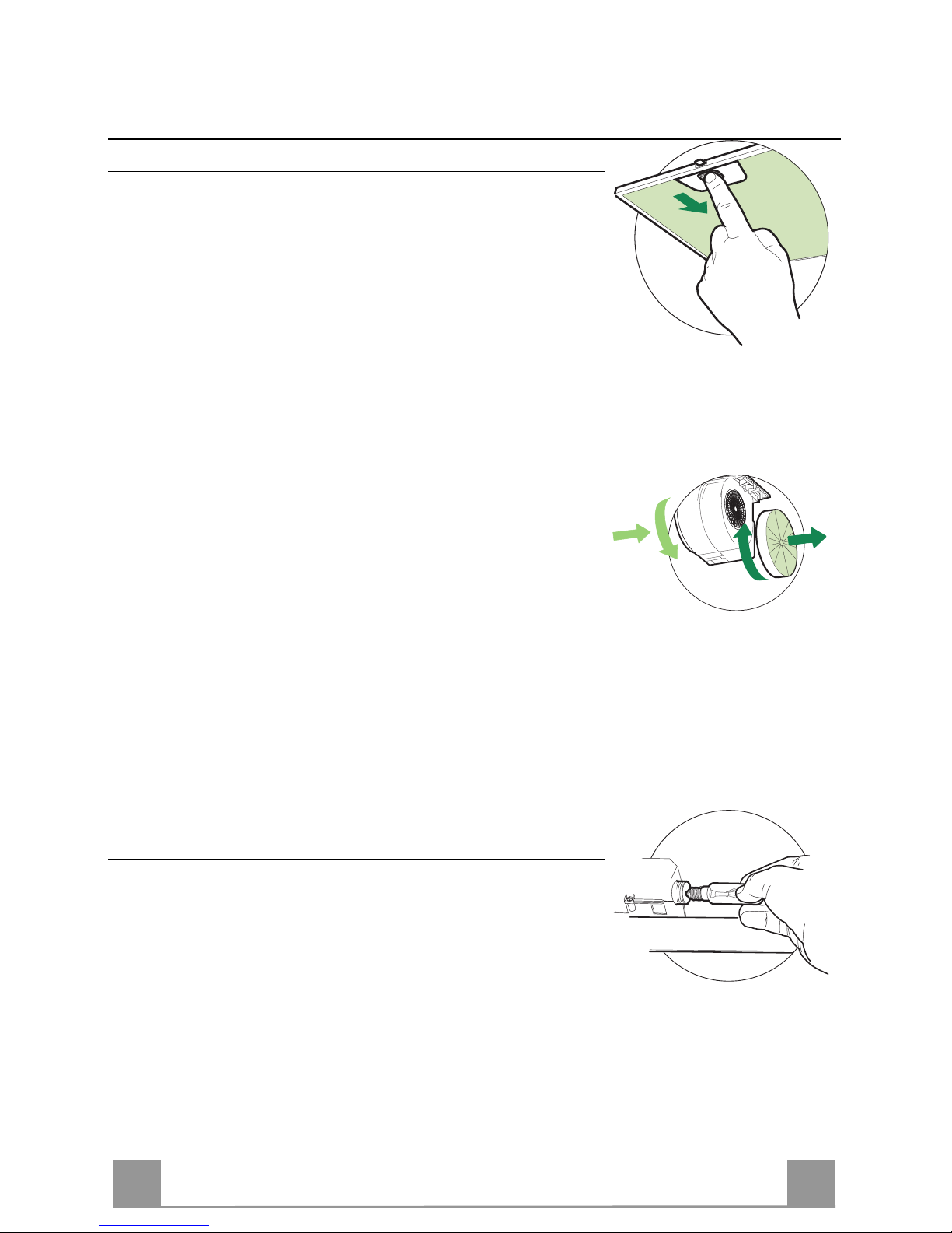
• Togliere i Filtri uno alla volta, spingendoli verso la parte posteriore del gruppo e tirando contemporaneamente verso il
basso.
• Lavare i Filtri evitando di piegarli, e lasciarli asciugare prima di rimontarli.
• Rimontarli facendo attenzione a mantenere la maniglia verso
la parte visibile esterna
Filtri antiodore al Carbone attivo (Versione Filtrante)
Il Filtro antiodore al Carbone attivo non è lavabile e non è rigenerabile, va sostituito ogni 4 mesi circa di utilizzo o più frequentemente, per un uso particolarmente intenso.
SOSTITUZIONE
• Togliere i Filtri antigrasso.
• Rimuovere i Filtri antiodore al Carbone attivo saturi, come indicato (A).
• Montare i nuovi Filtri, come indicato (B).
• Rimontare i Filtri antigrasso.
A
B
Illuminazione
SOSTITUZIONE LAMPADE
Lampade a incandescenza da 40 W
• Togliere i Filtri antigrasso metallici.
• Svitare le Lampade e sostituirle con nuove di uguali caratteristiche.
• Rimontare i Filtri antigrasso metallici.
Page 14
EN
114
RECOMMENDATIONS AND SUGGESTIONS
INSTALLATION
• The manufacturer will not be held liable for any damages resulting
from incorrect or improper installation.
• T he minimum safety di stance between the cooker top and the extrac tor hood is 650 mm.
• Check that the mains voltage corresponds to that indicated on the
rating plate fixed to the inside of the hood.
• For Class I appli ances , c heck t hat th e domesti c po wer s uppl y gua ran tees adequate earthing.
Connect the extractor t o the exhaust flue through a pipe of minimum
diameter 120 mm. The route of the flue must be as short as possible.
• Do not c onnect the extr actor hood to ex haust ducts carryi ng combustion fumes (boilers, fireplaces, etc.).
• If the extractor is used in conjunction with non-electrical appliances
(e.g. gas burning appliances), a suffi cient degree of aeration must be
guaranteed in the room in order to prevent the backflow of exhaust
gas. The kitchen must h ave an opening communicati ng directly with
the open air in order to guarantee the entry of clean air.
USE
• The extractor hood has been desi gne d exc l usi vely for domes tic us e to
eliminate kitchen smells.
• Never use the hood for purposes other than for which i t has ben designed.
• Never leave high naked flames under the hood when it is in operation.
• Adjust the flame i ntensity to direct it onto the bottom of the pan only,
making sure that it does not engulf the sides.
• Deep fat fryers must be continuously monitored during use: overheated oil can burst into flames.
• The hood should not be used by chil dren or pers ons not inst ructed in
its correct use.
MAINTENANCE
• Switch off or unplug the appliance from the mains supply before carrying out any maintenance work.
• Clean and/or replace the Filters after the specified time period.
• Clean the hood using a damp cloth and a neutral liquid detergent.
650 mm min.
Page 15

EN
115
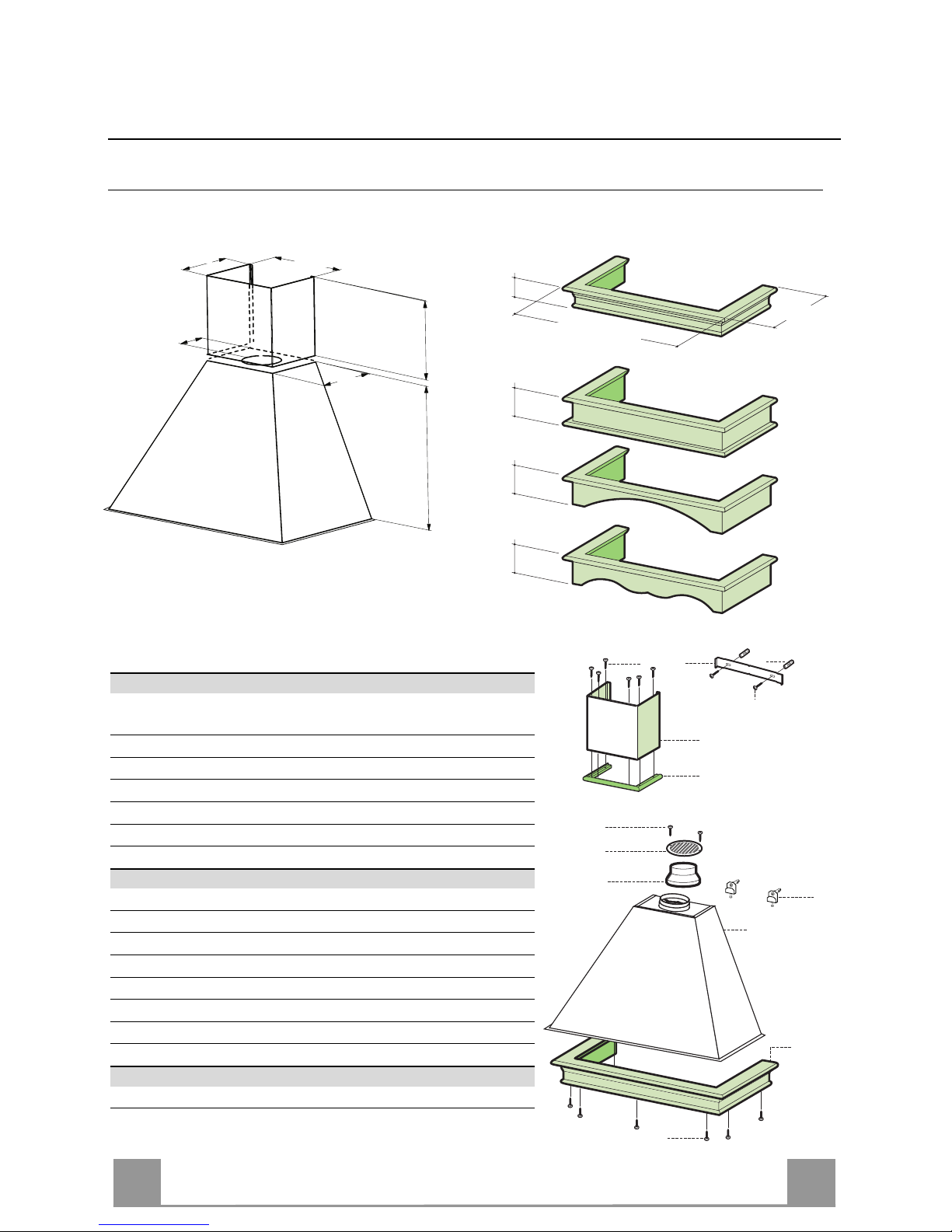
CHARACTERISTICS
Dimensions
110145
598 / 898 /1198
500
145145
500
260
212
275
200
100
Components
Ref. Q.ty Product Components
1 1 Hood Body, complete with: Controls, Light, Blower,
Filters
2 1 Chimney
8 1 Air Outlet Grill
9 1 Reducer Flange ø 150-120 mm
10 1 Shelf Frame (optio nal)
20 1 Wooden Profile (optional)
Ref. Q.ty Installation Components
7.2 1 Chimney Fixing Brackets
11 2 Wall Plugs
11a 2 Wall Plugs SB 12/10
12a 2 Screws 4,2 x 44,4
12e 2 Screws 2,9 x 12,7
12m 6 Screws 2,9 x 18
12n 7 Screws 3,5 x 16
Q.ty Documentation
1 Instruction Manual
1
2
12m
20
7.2
12n
10
11
12a
12e
8
9
11a
Page 16

EN
116
INSTALLATION
Wall drilling and bracket fixing
Hood dimension share X
60 cm 128 mm
90 cm 150 mm
120 cm 175 mm
Wall marking:
• Draw a vertical line on the supporting wall up to the ceiling, or as high as practical, at the
centre of the area in which the hood will be installed.
• Draw a horizontal line at 650 mm above the hob.
• Mark a reference point as indicated at X mm (see X on picture) from the vertical reference
line and 395 mm above the horizontal reference line.
• Repeat this operation on the other side.
• Drill at the points marked, using a ø 12 mm drill bit.
• Insert the bracket plugs 11a into the holes and screw into place.
• Place bracket 7.2 on the wall as shown, 750 mm above the horizontal reference line, align-
ing the centre (notch) with the vertical reference line.
• Mark the wall at the centres of the holes in the bracket.
• Drill ø 8 mm holes at all the centre points marked.
• Insert the wall plugs 11 in the holes.
• Fix the brackets using the 12a screws (4,2 x 44,4) supplied.
11a
650 min.
750
7.2
XX
395
Page 17

EN
117
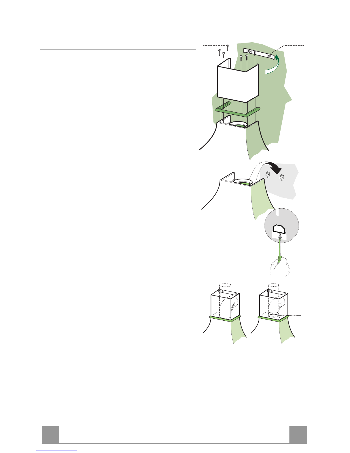
Flue assembly
• Slightly widen the two sides of the flue and hook
them behind the bracket 7.2 , making sure that they
are well seated.
• Insert the wooden profile 20 between the hood body
and the flue.
• Fix the lower section of the flue and the cable raceway to the hood body from above, using the 6 screws
12m (2.9 x 18) provided.
7.212m
20
Mounting the hood body
• Adjust the two screws Vr, on brackets 11a, to a
minimum.
• Hook the hood canopy onto the two brackets 11a.
• Remove the metal grease filters by turning the handles provided.
• From inside the hood canopy, adjust the screws Vr to
set the Hood Canopy level.
Vr
Connections
DUCTED VERSION AIR EXHAUST SYSTEM
When installing the ducted version, connect the hood to
the chimney using either a flexible or rigid pipe ø 150
or 120 mm, the choice of which is left to the installer.
• To install a ø 120 mm air exhaust connection, insert
the reducer flange 9 on the hood body outlet.
• Fix the pipe in position using sufficient pipe clamps
(not supplied).
• Remove any activated charcoal filters.
9
ø 120ø 150
Page 18

EN
118
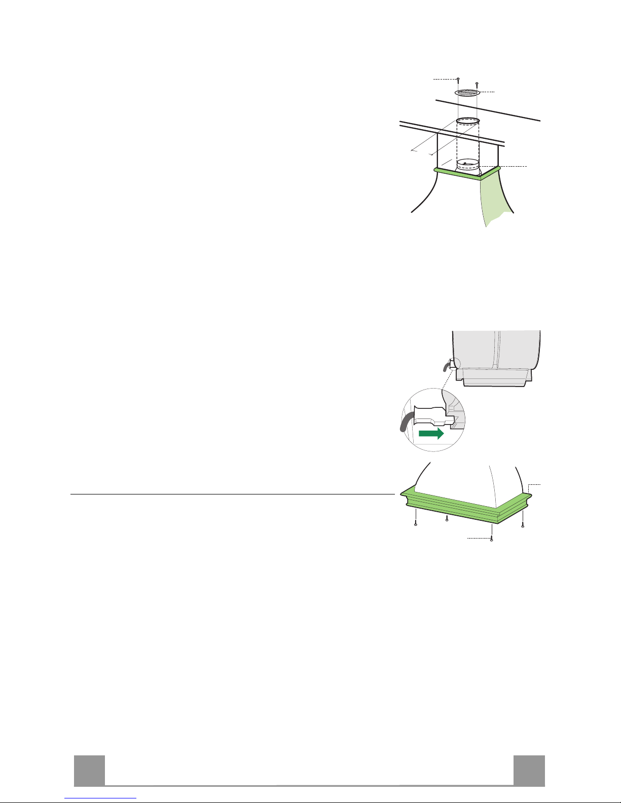
RECIRCULATION VERSION AIR OUTLET
• Cut a hole ø 125 mm in any shelf that may be positioned over
the hood.
• Insert the reducer flange 9 on the hood body outlet.
• Connect the flange to the outlet on the shelf over the hood using a flexible or rigid pipe ø120 mm.
• Fix the pipe in position using sufficient pipe clamps (not supplied).
• Fix the directional grille 8 on the recirculation air outlet using
the 2 screws 12e (2,9 x 9,5) provided.
• Ensure that the activated charcoal filters have been inserted.
9
ø 125
8
12e
ELECTRICAL CONNECTION
• Connect the hood to the mains through a two-pole switch having a contact gap of at least 3 mm.
• Remove the grease filters (see paragraph Maintenance) being
sure that the connector of the feeding cable is correctly inserted
in the socket placed on the side of the fan.
Fitting Shelf frame
• Rest the shelf frame 10 (optional) over the bottom edge of the
hood body, aligning the fixing holes.
• Fix from below using the 4 screws 12n (3.5 x 16) provided..
12n
10
Page 19

EN
119
USE
1
1
0
1
0
2
3
L
M
V
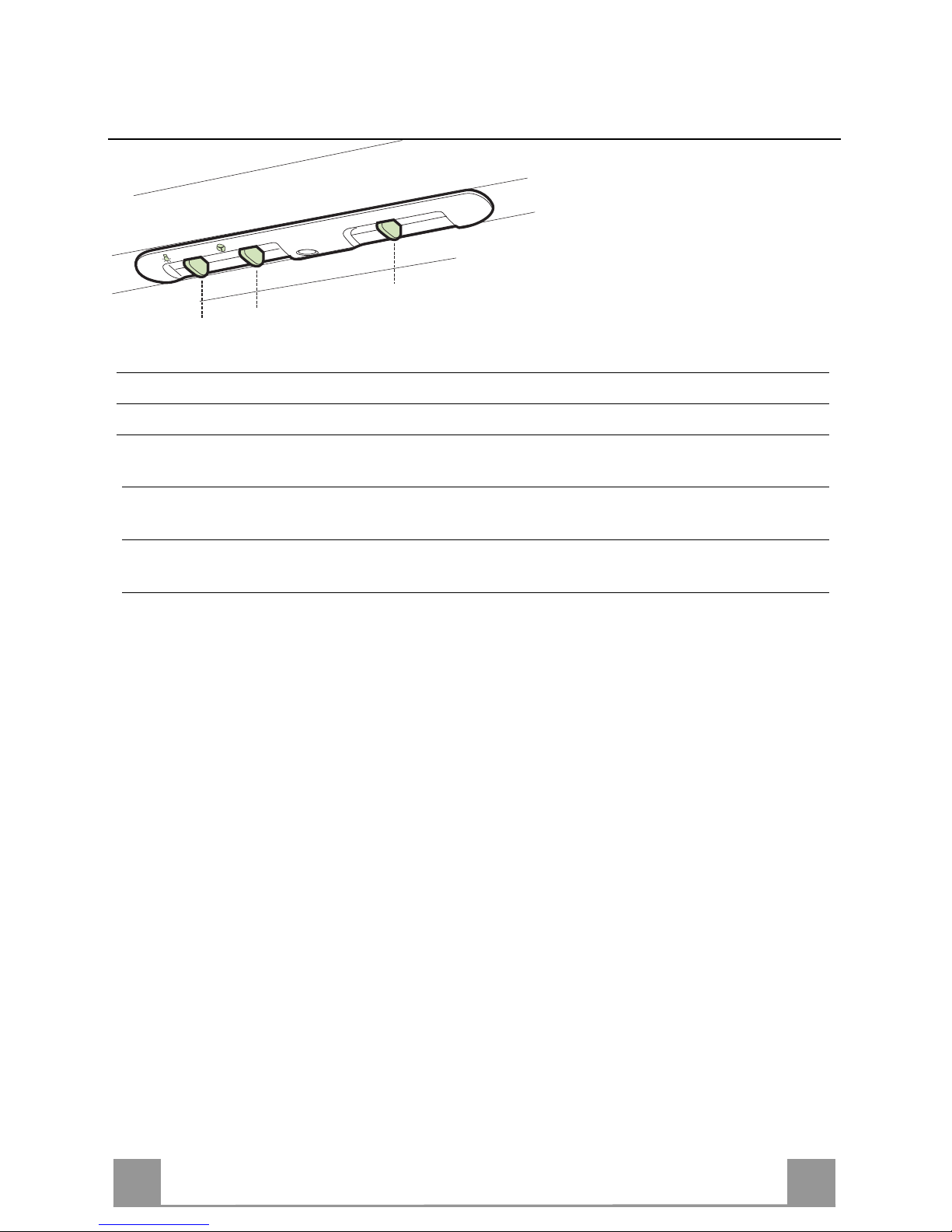
L Light Switches the lighting system on and off
M Motor Switches the extractor motor on and off
V Speed Sets the operating speed of the extractor:
1. Low speed, used for a continuous and silent air change in the presence of
light cooking vapour.
2. Medium speed, suitable for most operating conditions given the optimum
treated air flow/noise level ratio.
3. Maximum speed, used for eliminating the highest cooking vapour emission, including long periods.
Page 20

EN
220
MAINTENANCE
Grease filters
CLEANING METAL SELF- SUPPORTING GREASE FILTERS
• The filters must be cleaned every 2 months of operation, or
more frequently for particularly heavy usage, and can be washed in a dishwasher.
• Remove the filters one at a time by pushing them towards
the back of the group and pulling down at the same time.
• Wash the filters, taking care not to bend them. Allow them
to dry before refitting.
• When refitting the filters, make sure that the handle is visible
on the outside.
Activated charcoal filter (Recirculation version)
These filters are not washable and cannot be regenerated, and
must be replaced approximately every 4 months of operation, or
more frequently with heavy usage.
REPLACING THE ACTIVATED CHARCOAL FIL T ER
• Remove the metal grease filters
• Remove the saturated activated charcoal filter as shown (A).
• Fit the new filters (B).
• Replace the metal grease filters.
A
B
Lighting
LIGHT REPLACEMENT
40 W incandescent light.
• Remove the metal grease filters.
• Unscrew the bulbs and replace them with new ones having the
same characteristics.
• Replace the metal grease filters.
Page 21

FR
221
CONSEILS ET SUGGESTIONS
INSTALLATION
• Le fabricant décline toute responsabilité en cas de dommage dû à
une installation non correcte ou non conforme aux règles de l’art.
• La distance mi nimale de sécurité entre l e plan de cuisson et la hotte
doit être de 650 mm au moins.
• Vérifier que la tens i on du sec teu r co rres pond à la v al eur qui fi gu re s ur
la plaquette apposée à l’intérieur de la hotte.
• Pour les Appareils appartenant à la Ière Classe, veiller à ce que la
mise à la terre de l’installation électrique domestique ait été effectuée
conformément aux normes en vigueur.
• Connecter la hotte à la sortie d’air aspiré à l’aide d’une tuyauterie
d’un diamètre égal ou supérieur à 120 mm. Le parcours de la
tuyauterie doit être le plus court possible.
• Eviter de connecter la hotte à des conduites d’évacuation de fumées
issues d’une combustion tel que (Chaudière, cheminée, etc…).
• Si vous utilisez des appareils qui ne fonctionnent pas à l’électricité
dans la pièce ou est installée la hotte (par exemple: des appareils
fonctionnant au gaz), vous devez prévoir une aération suffisante du
milieu. Si la cuisine en est dépourvue, pratiquez une ouverture qui
communique avec l’extérieur pour garantir l’infiltration de l’air pur.
UTILISATION
• La hotte a été conç ue exclusivement pour l’us age domestique, dans
le but d’éliminer les odeurs de la cuisine.
• Ne jamais utiliser abusivement la hotte.
• Ne pas laisser l es flammes libres à forte intensité quand la hotte est
en service.
• Toujours régler les flammes de manière à éviter toute sortie latérale
de ces dernières par rapport au fond des marmites.
• Contrôler les friteuses lors de l’utilisation car l’huile surchauffée
pourrait s’enflammer.
• La hotte ne doit pas être utilisée par des enfants ou des personnes ne
pouvant pas assurer une utilisation correcte.
ENTRETIEN
• Avant de procéder à toute opération d’entretien, retirer la hotte en
retirant la fiche ou en actionnant l’interrupteur général.
• Effectuer un entretien scrupuleux et en temps dû des Filtres, à la
cadence conseillée.
• Pour le nettoyage des surfaces de la hotte, il suffit d’utiliser un
650 mm min.
Page 22

FR
222
CARACTERISTIQUES
Encombrement
110145
598 / 898 /1198
500
145145
500
260
212
275
200
100
Composants
Réf. Q.té Composants de Produit
1 1 Corps Hotte équipé de:Comandes,
Lumière,Groupe Ventilateur,Filtres
2 1 Cheminée
8 1 Grille orientée Sortie de l’Air
9 1 Flasque de Réduction ø 150-1 20 mm
10 1 Cadre de la Tablette (si fournie)
20 1 Profilé e n bois (si fournie)
Réf. Q.té Composants pour l ’installation
7.2 1 Brides Fixation Cheminé e
11 2 Chevilles
11a 2 Chevilles SB 12/10
12a 2 Vis 4,2 x 44,4
12e 2 Vis 2,9 x 12,7
12m 6 Vis 2,9 x 18
12n 7 Vis 3,5 x 16
Q.té Documentation
1 Manuel d’instructions
1
2
12m
20
7.2
12n
10
11
12a
12e
8
9
11a
Page 23

FR
223
INSTALLATION
Perçage Paroi et Fixation Brides
Hotte dimension Quota X
60 cm 128 mm
90 cm 150 mm
120 cm 175 mm
Tracer sur la paroi:
• une ligne verticale allant jusqu’au plafond ou à la limite supérieure, au centre de la zone
prévue pour le montage de la hotte;
• une ligne horizontale à 650 mm min. au-dessus du plan de cuisson.
• Marquer comme indiqué, un point de référence à X mm (voir X sur dessin en annexe) de la
ligne verticale de repère, et 395 mm au-dessus de la ligne horizontale de repère.
• Répéter cette opération sur le côté opposé.
• Percer des trous de ø 12 mm. en correspondance des points marqués.
• Insérer les chevilles avec bride 11a dans les trous puis visser.
• Poser comme indiqué la bride 7.2 à 750 mm. au-dessus de la ligne horizontale, en alignant
son centre (découpes) sur la ligne verticale de repère.
• Marquer les centres des trous rainurés de la bride.
• Percer de ø 8 mm tous les points marqués.
• Insérer les chevilles 11 dans les trous.
• Fixer les brides en utilisant les vis 12a (4,2 x 44,4) fournies.
11a
650 min.
750
7.2
XX
395
Page 24

FR
224
Montage Cheminée
• Elargir légèrement les deux bords latériaux, et les
accrocher derrières la bride 7.2; refermer jusqu’à la
butée.
• Insérer le Profilé en bois 20 entre le Corps de la
Hotte et la Cheminée.
• Fixer depuis le haut la partie inférieure de la Cheminée et la Baguette au Corps de la Hotte, au moyen de
6 Vis 12m (2,9 x 18) fournies avec l’appareil.
7.212m
20
Montage Corps Hotte
• Régler les deux vis Vr, des brides 11a, en début de
course.
• Accrocher le corps de la hotte aux 2 brides 11a.
• Enlever les filtres Anti-graisse, en intervenant sur les
poignées spécialement prévues.
• Depuis l’intérieur du corps de la hotte, intervenir sur
les Vis Vr pour niveler le Corps de la Hotte.
Vr
Branchements
SORTIE AIR VERSION ASPIRANTE
En cas d’installation en version aspirante, brancher la
hotte à la tuyauterie de sortie via un tube ri-gide ou
flexible de ø 150 ou 120 mm, au choix de l’installateur.
• En cas de branchement avec un tube de ø120 mm,
insérer le flasque de réduction 9 sur la sortie du corps
de la hotte.
• Fixer le tube par des colliers appropriés. Le matériau
nécessaire n’est pas fourni.
• Retirer les éventuels filtres anti-odeur au charbon
actif.
9
ø 120ø 150
Page 25

FR
225
SORTIE AIR VERSION FILTRANTE
• Percer un trou de ø 125 mm. sur l’éventuelle Tablette qui se
trouve au-dessus de la Hotte.
• Insérer le flasque de réduction 9 sur la sortie du corps de la
hotte.
• Connecter la Flasque au trou de sortie sur la Tablette qui se
trouve au-dessus de la Hotte, au moyen d’un tuyau rigide ou
flexible de ø120 mm.
• Fixer le tube par des colliers appropriés. Le matériau nécessaire n’est pas fourni.
• Fixer la Grille orientée 8 sur la sortie de l’air recyclé à l’aide
de 2 Vis 12e (2,9 x 9,5) fournies avec l’appareil.
• S’assurer de la présence des filtres anti-odeur au charbon actif.
9
ø 125
8
12e
BRANCHEMENT ELECTRIQUE
• Brancher la hotte sur le secteur en interposant un interrupteur
bipolaire avec ouverture des contacts d’au moins 3 mm.
• Enlever les filtres à graisse (voir § "Entretien") et s'assurer que
le connecteur du câble d'alimentation soit bien branché dans la
prise du diffuseur.
Montage du Cadre de la tablette
• Poser le Cadre de la tablette 10 (si fournie) sur le rebord inférieur du Corps de la Hotte, en alignant les trous de fixation.
• Fixer depuis le bas à l’aide de 4 vis 12n (3,5 x 16) fournies
avec l’appareil.
12n
10
Page 26

FR
226
UTILISATION
1
1
0
1
0
2
3
L
M
V
L Lumières Allume et éteint l’éclairage.
M Moteur Allume et éteint le moteur aspiration
V Vitesses Détermine les vitesses d’exploitation ainsi subdivisées:
1.Vitesse minimale, pour un rechange d’air permanent particulièrement
silencieux en cas de faibles vapeurs de cuisson.
2.Vitesse moyenne pour la plupart des conditions d’utilisation, étant donné
lerapport optimal entre débit d’air traité et niveau sonore.
3.Vitesse maximum, pour faire face aux émissions maximum de vapeur de
cuisson, même pendant des temps prolongés.e
Page 27

FR
227
ENTRETIEN
Filtres anti-graisse
NETTOYAGE FILTRES ANTI-GRAISSE METALLIQUES AUTOPORTEURS
• Lavables au lave-vaisselle, ils doivent être lavés environ tous
les 2 mois d’emploi ou plus fréquemment en cas d’emploi particulièrement intense.
• Retirer les filtres l’un aprés l’autre, en les poussant vers la partie arrière du groupe et en tirant simultanément vers le bas.
• Laver les filtres en évitant de les plier et les laisser sécher avant
de les remonter.
• Remonter les filtres en veillant à ce que la poignée reste vers la
partie visible externe
Filtre anti-odeur (Version filtrante)
Il ne sont pas lavables ni régénérables, il faut les remplacer au
moins tous les 4 mois d’emploi ou plus fréquemment en cas
d’emploi particulièrement intense.
REMPLACEMENT FILTRE AU CHARBON ACTIF
• Retirer les filtres anti-graisse métalliques.
• Retirer les filtres anti-odeur au charbon actif saturés, comme
indiqué (A).
• Monter les nouveaux filtres (B).
• Remonter le filtres anti-graisse métalliques.
A
B
Eclairage
REMPLACEMENT LAMPES
Lampes à incandescence de 40 W
• Retirer les filtres anti-graisse métalliques.
• Dévisser les lampes et les remplacer par de nouvelles avec les
mêmes caractéristiques.
• Remonter les filtres anti-graisse métalliques.
Page 28

DE
228
EMPFEHLUNGEN UND HINWEISE
MONTAGE
• Der Hersteller haftet nicht für Schäden, die auf eine fehle rhafte und
unsachgemäße Montage zurückzuführen sind.
• Der minimale Sicherheitsabstand zwischen Kochmulde und Haube
muss 650 mm betragen.
• Prüfen, ob di e Netzspannung mi t dem Wert auf dem im Haubeninn eren angebrachten Schild übereinstimmt.
• Bei Geräten der Kl asse I ist sicherzustell en, dass die elektrische Anlage des Wohnhauses über eine vorschriftsmäßige Erdung verfügt.
• Das Anschlussrohr der Haube zur Luftaustrittsöffnung muss einen
Durchmesser von 120 mm oder darüber aufweisen. Der Roh rverlauf
muss so kurz wie möglich sein.
• Die Haube darf an keine Entlüftungs schäc hte angeschlos sen werden,
in die Verbrennungsgase (Heizkessel, Kamine usw.) geleitet werden.
• Werden im Raum außer der Dunstabzugshaube and ere, nicht elektrisch betriebene (z.B. gasbe triebene) Geräte verwend et, muss für eine ausreichende Belüftung ges orgt werden. Sollte die Küche di esbezüglich nicht entsprechen, i st an einer Aussenwa nd eine Öffnung anzubringen, die Frischluftzufuhr gewährleistet.
BEDIENUNG
• Die Dunstabzugshaube ist ausschließlich zum Einsatz im privaten
Haushalt und zur Beseitigung von Küchengerüchen vorgesehen.
• Unsachgemäßer Einsatz der Haube ist zu unterlassen.
• Große Flammen bei eingeschalteter Haube niemals unbedeckt lassen.
• Die Intensivität der Fl amme ist so z u regulieren, das s sie den T opfboden nicht überragt.
• Frittiergeräte müssen während des Gebrauchs stets beaufsichtigt
werden: überhitztes Öl kann sich entzünden.
• Die Dunstabzugshaub e darf vo n Kin dern ode r Pers onen, di e hinsic htlich der Bedienung nicht unterwiesen wurden, keinesfalls verwendet
werden.
WARTUNG
• Bevor Wartun gsarbeiten durchgef ührt werden, muss di e Stromzufuhr
zur Haube unterbrochen werden, indem der Stecker gezogen oder
der Hauptschalter abgeschaltet wird.
• Bei der Filterwartung müssen die vom Hersteller empfohlenen Zeiträume zum Austauschen der Filter genauestens eingehalten werden.
• Zur Reinigung der Haubenflächen Wir empfehlen ein feuchtes Tuch
und ein mildes Flüssigreinigungsmittel.
650 mm min.
Page 29

DE
229
CHARAKTERISTIKEN
Platzbedarf
110145
598 / 898 /1198
500
145145
500
260
212
275
200
100
Komponenten
Pos. St. Produktkomponenten
1 1 Ha ubenkörper mit Schaltern,Beleuchtung,
Gebläsegruppe,Filter
2 1 Kamin
8 1 Luftleitgitter Luftaustritt
9 1 Reduzierfl ansch ø 150-120 mm
10 1 Bordleiste (option)
20 1 Holzprofil (option)
Pos. St. Montagekomponenten
7.2 1 Befestigungsbü gel Kami n
11 2 Bügel
11a 2 Bügel SB 12/1 0
12a 2 Schrauben 4,2 x 44,4
12e 2 Schrauben 2,9 x 12,7
12m 6 Schrauben 2,9 x 18
12n 7 Schrauben 3,5 x 16
St. Dokumentation
1 Bedienungsanleitung
1
2
12m
20
7.2
12n
10
11
12a
12e
8
9
11a
Page 30

DE
330
MONTAGE
Bohren der Befestigungslöcher und Fixieren der Befestigungsbügel
Maß der Haube Breite X
60 cm 128 mm
90 cm 150 mm
120 cm 175 mm
Nachstehende Linien an die Wand zeichnen:
• eine vertikale Linie bis zur Decke oder oberen Begrenzung, und zwar in der Mitte des Bereiches, in dem die Haube montiert werden soll;
• eine horizontale Linie: mit einem minimalen Abstand von 650 mm zur Kochfläche.
• Wie beschrieben einen Bezugspunkt X mm (X=s. Zeichnung mit tafel) von der vertikalen
Bezugslinie und 395 mm oberhalb der horizontalen Bezugslinie kennzeichnen.
• Gleichermaßen an der gegenüberliegenden Seite vorgehen.
• Die gekennzeichneten Punkte mit einem Bohrer ø 12 mm bohren.
• Die Dübel mit dem Bügel 11a in die Bohrungen einfügen und festschrauben.
• Den Bügel 7.2 750 mm oberhalb der horizontalen Bezugsliniekennzeichnen positionieren,
wobei die Mitte (Einschnitte) auf die vertikale Bezugslinie auszurichten ist.
• Die Mitte der beiden Bügellöcher an der Wand markieren.
• Mit einem Bohrer ø 8 mm die markierten Punkte bohren.
• Die Dübel 11 in die Bohrungen einfügen.
• Die Bügel mit den mitgelieferten Schrauben 12a (4,2 x 44,4) fixieren.
11a
650 min.
750
7.2
XX
395
Page 31

DE
331
Kaminmontage
• Die beiden seitlichen Schenkel leicht auseinanderbiegen, hinter dem Bügel 7.2 einhängen und bis zum
Anschlag wieder schließen.
• Das Holzprofil 20 zwischen Haubenkörper und Ka-
min einfügen.
• Von der Oberseite her den Unterteil des Kamins und
die Kabelabdeckung zum Haubenkörper mit den 6
mitgelieferten Schrauben 12m (2,9 x 18) fixieren.
7.212m
20
Montage des Haubenkörpers
• Die beiden Schrauben Vr der Bügel 11a so regulieren, dass sie nur bis zum Gewindebeginn eingeschraubt sind.
• Den Haubenkörper bei den 2 Bügeln 11a einhaken.
• Die Fettfilter mit den entsprechenden Griffen demontieren.
• Vom Haubeninneren her den Haubenkörper mit Hilfe
der Schrauben Vr ausrichten.
Vr
Anschlüss in abluftversion
Bei Abluftbetrieb kann die Haube vom Installateur
wahlweise mittels Rohr oder Schlauch (ø 150 oder 120
mm) an die Außenrohrleitung angeschlossen werden.
• Bei Verwendung eines Anschlussrohres ø 120 den
Reduzierflansch 9 am Haubenaustritt anbringen.
• Das Rohr mit geeigneten Rohrschellen fixieren. Das
hierzu erforderliche Material wird nicht mitgeliefert.
• Eventuell vorhandene Aktivkohlefilter entnehmen.
9
ø 120ø 150
Page 32

DE
332
ANSCHLUSS IN UMLUFTVERSION
• In das eventuell über der Haube vorhandene Bord ein Loch ø
125 mm bohren.
• Den Reduzierflansch 9 am Haubenaustritt anbringen.
• Den Flansch beim Luftaustritt am Bord oberhalb der Haube
mittels Rohr oder Schlauch ø120 mm anschließen.
• Das Rohr mit geeigneten Rohrschellen fixieren. Das hierzu
erforderliche Material wird nicht mitgeliefert.
• Das Luftleitgitter 8 mit Hilfe von 2 der mitgelieferten Schrau-
ben 12e (2,9 x 9,5) beim Austritt der rückzuführenden Luft fixieren.
• Sicherstellen, dass der Aktivkohle-Geruchsfilter vorhanden ist.
9
ø 125
8
12e
ELEKTROANSCHLUSS
• Bei Anschluss der Haube an das Stromnetz muss ein zweipoliger Schalter mit einem Öffnungsweg von mindestens 3 mm
zwischengeschaltet werden.
• Entfernen Sie die Fettfilter (s. Abschnitt „Wartung“) und versichern Sie sich, daß die Kabelverbindung in die Steckdose des
Gebläses einwandfrei eingesteckt wird.
Montage der Bordleiste
• Die Bordleiste 10 (option) an die Unterkante des Haubenkör-
pers legen und auf die Befestigungs– löcher ausrichten.
• Von der Unterseite her mit den 4 mitgelieferten Schrauben 12n
(3,5 x 16) fixieren.
12n
10
Page 33

DE
333
BEDIENUNG
1
1
0
1
0
2
3
L
M
V
L Beleucht Schaltet die Beleuchtung ein und aus
M Motor schaltet den Gebläsemotor ein und aus
V Geschw. steuert folgende Geschwindigkeitsstufen:
1.geringste Gebläsestufe, diese Stufe ist für einen ständigen und besonders
leisen Luftaustausch bei geringer Kochdunstentwicklung geeignet;
2.mittlere Gebläsestufe, eignet sichaufgrund des guten Verhältnisses zwischen Fördervolumen und Geräuschentwicklung für die meisten Anwendungssituationen;
3.höchste Gebläsestufe, eignet sich für starke Kochdunstentwicklung, auch
über längere Zeit hin.
Page 34

DE
334
WARTUNG
Fettfilter
SELBSTTRAGENDER METALLFET TFILTER REINIGUNG
• Sie müssen nach 2-monatigem Betrieb bzw. bei starkem
Einsatz auch häufiger gereinigt werden, was im Geschirrspüler möglich ist.
• Die Filter nacheinander aushaken, indem sie auf die Rückseite der Gruppe geschoben und gleichzeitig nach unten
gezogen werden.
• Die Filter reinigen (darauf achten, sie nicht zu verbiegen)
und vor der Remontage trocknen lassen.
• Bei der Remontage ist darauf zu achten, dass sich der Griff
auf der sichtbaren Außenseite befindet.
Geruchsfilter (Umluftversion)
Sie können weder gewaschen noch wiederverwendet werden und
sind alle 4 Betriebsmonate bzw. bei starkem Einsatz auch häufiger auszutauschen.
AUSTAUSCHEN DER AKTIVKOHL E FIL T ER
• Die Metallfettfilter entnehmen.
• Den gesättigten Aktivkohle-Geruchsfilter wie gezeigt entfernen (A).
• Die neuen Filter wie gezeigt montieren (B).
• Die Metallfettfilter wieder montieren.
A
B
Beleuchtung
AUSWECHSELN DER LAMPEN
Glühlampen zu 40W
• Die Metallfettfilter entfernen.
• Die Lampen ausschrauben und durch gleichwertige ersetzen.
• Die Metallfettfilter wieder montieren.
Page 35

TR
335
TAVSIYELER VE ÖNERILER
MONTAJ
• Yalnιş veya eksik montajdan doğan herhangi bir zararιn
sorumluluğu üreticiye ait değildir.
• Davlumbaz ile pişirici cihazιn ocak kιsmι arasιndaki minimum
güvenlik mesafesi 650 mm.dir.
• Besleme voltajιnιn, davlumbaz içerisine yerleştirilen bilgi
etiketinde belirtilenle aynι olup olmadιğιnι kontrol edin.
• Sιnιf I elektrikli aletleri için, güç kaynağιnιn yeterli topraklamayι
sağlayιp sağlamadιğιnι kontrol edin. Minimum 120 mm çapιnda
bir boru yoluyla davlumbazι çιkιş bacasιna bağlayιn. Baca
bağlantιsι mümkün oldu- ğunca kιsa olmal ιdιr.
• Davlumbaz borus unu yanιcι duman taşιyan baca deliğine (buhar
kazanι, şömine, vb .) bağlamayιn.
• Davlumbazιn elektrikle çalιşmayan aletlerle (örneğin; gazlι
cihazlar) bağιntιlι olarak kullanιlmamasι halinde çιkιş gazιnιn geri
tepmesini önlemek amacιyla odada yeterli bir havalandιrma
sağlanmalιdιr.Temiz hava girişini temin etmek için mutfakta
doğrudan dιşarιya açιlan b ir açιklιk bulunmalιdιr.
KULLANIM
• Davlumbaz mutfaktaki kokularιn emilmesi amacιyla evlerde
kullanιm için tasarlanmιştιr.Ticari ve endüstriyel amaçlar için
kullanmayιnιz.
• Davlumbazι tasarlandιğι amaçlarιn dιşιnda kesinlikle
kullanmayιnιz.
• Davlumbaz çalιşιrken altιnda kesinlikle yüksek çιplak ateş
bιrakmayιn.
• Alev yoğunluğunu doğrudan tencerenin altιnda kalacak şekilde
ayarlayιn, kenarlarιnι sarmadιğιndan emin olun.
• Yağda kιzartma tavalarιnι kullanιrken sürekli olarak takip edin:
fazla ιsιnan yağ tutuşabilir.
• Davlumbaz çocuklar veya doğru kullanιm konusunda bilgisi
olmayan kişiler tarafιndan kullanιlmamalιdιr.
BAKIM
• Herhangi bir bakιm işlemini gerçekleştirmeden önce davlumbazι
kapatιn veya fişini çιkarιn.
• Fil treleri belirtilen zamanlarda temizleyin ve / veya değiştirin.
• Cihazι nemli bir bez ve nötr bir sιvι deterjan kullanarak
temizleyin.
650 mm min.
Page 36

TR
336
ÖZELLIKLER
Boyutlar
110145
598 / 898 /1198
500
145145
500
260
212
275
200
100
Parçaları
Ref. Adet Ürün Parçaları
1 1 Aşağıdakilerden oluşan Davlumbaz Gövdesi:
Kumandalar, Lamba, Fan Grubu, Fi ltreler
2 1 Baca
8 1 Yönlendirmeli Izgara, çapı ø125 mm
9 1 Redüksiyon Flanşı , çapı ø 150-120 mm
10 1 Konsol Çer çevesi (isteğe bağlı)
20 1 Ahşap Profil (isteğe bağlı)
Rif. Adet Montaj Parçaları
7.2 1 Baca tesbit braketi
11 2 Dübel
11a 2 Dübel SB 12/10
12a 2 Vida 4,2 x 44,4
12e 2 Vida 2,9 x 12,7
12m 6 Viti 2,9 x 18
12n 7 Vida 3,5 x 16
Adet Belgeler
1 Talimat El Ki tapçığı
1
2
12m
20
7.2
12n
10
11
12a
12e
8
9
11a
Page 37

TR
337
MONTAJ
Duvarın Delinmesi ve Braketlerin Sabitlenmesi
Davlumbaz ebatları Kot X
90 cm 128 mm
90 cm 150 mm
120 cm 175 mm
Duvara şunları çiziniz:
• Tavana ya da üst sınıra uzanan ve davlumbazın monte edileceği yerin merkezinden geçen
dikey bir çizgi;
• Setüstü ocağın üzerinden 650 mm mesafeden geçen yatay bir çizgi;
• Şekilde gösterildiği gibi, yatay referans çizgisi üzerinden 395 mm mesafede, dikey referans
çizgisinin sağ tarafından ise X mm mesafede bulunan bir referans noktası işaretleyiniz (X =
resimdeki çizelgeye bakınız).
• Hizalamaya dikkat ederek aynı işlemi diğer taraftan da tekrar ediniz.
• İşaretlenen noktalara ø 12 mm çapında delikler açınız.
• Vida ve braketleriyle komple durumdaki dübelleri 11a deliklere yerleştirip vidaları sıkınız.
• Şekilde gösterildiği gibi braketi 7.2 yatay çizginin 750 mm üzerinden, tam orta kısmı
(çentik) dikey referans çizgisine hizalanacak şekilde duvara dayayınız.
• Braket deliklerinin ortasından duvara işaret koyunuz.
• İşaretlenen noktalara ø 8 mm çapında delikler açınız.
• Dübelleri 11 deliklere yerleştiriniz.
• Donanımdaki vidaları 12a (4,2 x 44,4) kullanarak braketi sabitleyiniz.
11a
650 min.
750
7.2
XX
395
Page 38

TR
338
Baca Montajı
• Bacanın iki adet yan eteğini hafifçe yanlara doğru
açınız, braketi 7.2 arkalarına takıp etekleri tekrar
sonuna dayanana kadar kapatınız.
• Ahşap profili 20 davlumbaz gövdesi ile baca arasına
yerleştiriniz.
• Bacanın alt kısmını ve profili üst taraftan davlumbaz
gövdesine donanımdaki 6 adet vidayı 12m (2,9 x 18)
kullanarak sabitleyiniz.
7.212m
20
Davlumbaz Gövdesi Montajı
• Braketlerin 11a iki adet vidasını Vr vidalanma
derinliklerinin başlangıç noktasında kalacak şekilde
yerleştiriniz.
• Davlumbaz gövdesini 2 adet brakete 11a geçiriniz.
• Filtreleri, grubun arkasına doğru bastırıp aynı anda
aşağı doğru çekerek teker teker çıkarınız.
• Davlumbaz gövdesinin iç tarafından vidalara Vr
müdahale ederek davlumbaz gövdesinin seviyesini
dengeleyiniz.
Vr
Bağlantılar
ASPİRATÖRLÜ MODEL HAVA ÇIKIŞI
Aspiratörlü modelin montajı için, davlumbaz, montörün
seçeceği 150 yada 120 mm çapında sert veya esnek bir
boru ile çıkış kanalına bağlanmalıdır.
• ø120 mm çapında boru ile bağlantı için, redüksiyon
flanşını (9) davlumbaz gövdesi çıkışına yerleştiriniz.
• Boruyu uygun kelepçelerle sıkarak sabitleyiniz. Bu
malzeme davlumbaz donanımıyla birlikte verilmemiştir.
• Varsa aktif karbonlu koku alma filtrelerini çıkarınız.
9
ø 120ø 150
Page 39

TR
339
FİLTRELİ MODEL HAVA ÇIKIŞI
• Davlumbazın üzerinde, eğer mevcut ise, yerleşik bulunan
konsola ø 125 mm çapında bir delik açınız.
• Redüksiyon flanşını 9 davlumbaz gövdesi çıkışına takınız.
• Flanşı ø 120 mm çapında esnek ya da sert bir boru ile
davlumbaz üzerindeki konsolda bulunan çıkış deliğine
bağlayınız.
• Boruyu uygun özellikte kelepçelerle sıkınız. Gereken malzeme
cihaz donanımıyla birlikte verilmemiştir.
• Yönlendirmeli ızgarayı 8 donanımdaki 2 adet vida ile 12e (2,9
x 9,5) çıkış noktasına sabitleyiniz.
• Aktif karbonlu koku filtrelerinin mevcut olduklarından emin
olunuz.
9
ø 125
8
12e
ELEKTRİK BAĞLANTISI
• Davlumbazı şebeke cereyanına bağlarken aray temas aralığı en
az 3 mm olan çift kutuplu bir elektrik anahtarı koyunuz.
• Yağ tutucu filtreleri çıkarınız (bakınız "Bakım" paragrafı) ve
besleme kablosu soketinin aspiratör prizine iyice takılmış olduğundan emin olunuz.
Konsol Çerçevesi Montajı
• Konsol çerçevesini 10 tesbit deliklerini hizalayarak davlumbaz
gövdesinin alt kenarı üzerinden duvara dayayınız.
• Donanımdaki 4 adet vidayı 12n (3,5 x 30) kullanarak alt
kısmından duvara sabitleyiniz.
12n
10
Page 40

TR
440
KULLANIM
1
1
0
1
0
2
3
L
M
V
L Lambalar Aydınlatmayı açar - kapatır
M Motor Aspiratör motorunu açar - kapatır.
V Hız Davlumbazın çalışma hızını belirler:
1. Minimum hız, az duman mevcut olduğunda gayet sessiz şekilde hava
dolaşımı sağlar.
2. Orta hız, genel kullanımın büyük kısmını kapsar, ses düzeyi ile hava
dolaşımı oranı mükemmeldir.
3. Maksimum hız, Hem çok yoğun duman, hem de uzun süreli pişirmelerde
kullanıma uygundur.
Page 41

TR
441
BAKIM
Yağ tutucu filtreler
METALİK YAĞ TUTU C U FİLTRELERİN TEMİZLENMESİ
• Bu filtreler bulaşık makinasında da yıkanabilir ve normal
kullanıldıklarında iki ayda bir, yoğun kullanım halinde ise
daha sıkça yıkanmalarıı gereklidir.
• Filtrleri, grubun arka tarafından ittirerek ve aynı anda aşağı
doğru çekerek tek tek çıkarınız.
• Filtreleri yıkarken eğip katlamayınız, tekrar monte etmeden
önce de kurutunuz.
• Monte ederken kulpun görünen dış tarafa doğru gelmesine
dikkat ediniz.
Aktif karbonlu koku giderici filtreler (Filtreli Model)
Aktif karbonlu koku giderici filtre yıkanmaz ve rejenere edilmez,
normal kullanımda yaklaşık 4 ayda bir, yoğun kullanımda daha
sıkça değiştirilmesi gerekir.
DEĞİŞTİRİLMESİ
• Yağ tutucu filtreleri çıkarınız.
• Doyum noktasına ulaşmış aktif karbonlu koku giderici filtreleri
(A) şeklinde gösterildiği gibi çıkarınız
• Yeni filtreleri (B) şeklinde gösterildiği gibi takınız.
• Yağ tutucu filtreleri tekrar monte ediniz.
A
B
Aydınlatma
AMPULLERİN DEĞİŞTİRİLMESİ
40 W akkor lambalar
• Metalik yağ tutucu filtreleri çıkarınız.
• Ampulleri gevşetip çıkarınız ve aynı özelliklere sahip yenileriyle değiştiriniz.
• Metalik yağ tutucu filtreleri tekrar takınız.
Page 42

Page 43

Page 44

436002916_ver1
Il simbolo sul prodotto o sulla c onfez i one i ndica che i l pr odott o non d eve es s ere c onsi dera to c om e un norm al e ri fiuto d omes ti co,
ma deve ess ere port ato n el p unt o di rac c olta appr opri at o per i l r ic iclaggi o di appar ec chi atur e el ettri ch e ed el ettr oni ch e. Prov v ede ndo a
smaltire q ues to pro d otto i n m odo a ppro pri ato, s i contri bui sc e a evi t are p ote nzial i c onse gu enze nega tiv e per l’ ambi en te e p er la s alute,
che potrebbero deri v ar e da un o s m al ti m ento ina de guato del prodotto. P er i nformazio ni pi ù dettagli ate sul riciclaggio di questo prodotto,
contattare l’uff icio comunale, il servizio locale di smaltimento rifiuti o il negozio in cui è stato acquistato il prodotto.
The symbol on the product or on its pac kaging indi c a tes t ha t thi s pr o duct may not b e tr e ated as household wast e. Instead i t s hal l
be handed ov er to the applicable c ollectio n point for the recyc ling of elec trical and electroni c equipm ent. By ensur ing this product is
disposed of correctly, you will help prevent potential negative cons equences for the environment and human health, which could otherwise be caus ed by in appr opr iat e wast e han dli ng of this produc t. F or mor e detai led infor mati o n about recyc li ng of this produc t , ple ase
contact your local city office, your household waste disposal service or the shop where you purchased the product.
Le symbole sur le produit ou so n em ball age i ndi que q ue c e prod uit ne pe ut êtr e trai té com m e déc het m éna ger. Il d oit pl ut ôt êtr e
remis au point de ramassage concerné, se chargeant du recyclage du matériel électrique et électronique. En vous assurant que ce
produit est él imi né correc temen t, vous favori sez l a préve ntion des conséq uenc es nég atives p our l’ envir onnem ent et la sa nté hum aine
qui, sinon, s er ai e nt l e r ésultat d’un traiteme nt inappropr i é d es d éc h ets d e c e produit. P our o bt enir plus de dé tai l s s ur l e rec yclage de ce
produit, veuillez prendre contact avec le bureau municipal de votre région, votre service d’élimination des déchets ménagers ou le
magasin où vo us av ez acheté le pro dui t.
Das Symbol auf dem Prod ukt oder seiner Verp acku ng weis t darauf hin, das s di eses Pro dukt n icht al s norm aler Haus halts abfal l
zu behand eln ist, s on der n an ein em S am mel pu nkt f ür das Recy cl ing v on elek tri sche n und elek troni sc he n Ger äte n ab geg ebe n w erde n
muss. Durc h Ihren Beitr a g zum korr ek te n Entsorge n dieses Pr odukts sc hützen Sie die Umwelt und die Ges u ndheit Ihr er M itmensch e n.
Umwelt und Gesundheit werden durch falsches Entsorgen gefährdet. Weitere Informationen über das Recycling dieses Produkts
erhalten Sie von Ihrem Rathaus, Ihrer Müllabfuhr oder dem Geschäft, in dem Sie das Produkt gekauft haben.
Ürün veya pak eti üzerindeki sembolü, bu ürünün norm al bir evsel atık olar ak görülmemesi v e bu tip elektrikli veya el ektronik
cihazları n atıldı ğı dönüşüm lü topl ama n oktal arına t erke dilm esi ger ektiğine işaret e der. B u ürünü g erekti ği gibi elim ine etm e kural ların a
uyarsanız çevre ve insan sağlığı üzerindeki olum suz etkilerini b ertaraf etmeye katk ı sağlamış olursunuz. B u ürünün geri d önüşüm
koşulları hakkında daha ayrıntılı bilgi için hudutları içinde bulunduğunuz belediyenin ilgili diaresine, atık yoketme servisine veya ürünün
satıcısına da nışınız.
Franke S.p.a.
Via Pignolini,2
37019 Peschiera del Garda (VR)
www.franke.it
73/23/CEE
Dir. 89/336/CEE
93/68/CEE
 Loading...