

Page 1

Instructions for use and installation
Cooker Hood
Istruzioni per l’uso e l’installazione
Cappa
Mode d’emploi et installation
Hotte de Cuisine
Bedienungsanleitung und Einrichtung
Dunstabzugshaube
Kullan
ım ve montaj talimatları
Davlumbaz
Instrukcja obsługi i instalacji
Okap kuchenny
FCH 906
GB
IT
FR
DE
TR
PL
Page 2

EN
2
2
Instructions Manual
INDEX
RECOMMENDATIONS AND SUGGESTIONS......................................................................................................................8
CHARACTERISTICS..............................................................................................................................................................9
INSTALLATION ....................................................................................................................................................................10
USE.......................................................................................................................................................................................13
MAINTENANCE....................................................................................................................................................................14
Page 3

IT
3
3
Libretto di Istruzioni
INDICE
CONSIGLI E SUGGERIMENTI ............................................................................................................................................16
CARATTERISTICHE............................................................................................................................................................17
INSTALLAZIONE..................................................................................................................................................................18
USO......................................................................................................................................................................................21
MANUTENZIONE.................................................................................................................................................................22
Page 4

FR
4
4
Manuel d’Instructions
SOMMAIRE
CONSEILS ET SUGGESTIONS ..........................................................................................................................................24
CARACTERISTIQUES.........................................................................................................................................................25
INSTALLATION ....................................................................................................................................................................26
UTILISATION........................................................................................................................................................................29
ENTRETIEN..........................................................................................................................................................................30
Page 5

DE
5
5
Bedienungsanleitung
INHALTSVERZEICHNIS
EMPFEHLUNGEN UND HINWEISE....................................................................................................................................32
CHARAKTERISTIKEN..........................................................................................................................................................33
MONTAGE............................................................................................................................................................................34
BEDIENUNG.........................................................................................................................................................................37
WARTUNG............................................................................................................................................................................38
Page 6

TR
6
6
Kullanim Kilavuku
IÇERIKLER
TAVSIYELER VE ÖNERILER ..............................................................................................................................................40
ÖZELLIKLER........................................................................................................................................................................41
MONTAJ...............................................................................................................................................................................42
KULLANIM............................................................................................................................................................................45
BAKIM...................................................................................................................................................................................46
Page 7

PL
7
7
Instrukcja Obslugi
SPIS TREŚCI
UWAGI I SUGESTIE.............................................................................................................................................................48
WŁAŚCIWOŚCI TECHNICZNE............................................................................................................................................49
INSTALACJA........................................................................................................................................................................50
UŻYTKOWANIE....................................................................................................................................................................53
KONSERWACJA..................................................................................................................................................................54
Page 8
EN
8
8
RECOMMENDATIONS AND SUGGESTIONS
The Instructions for Use apply to several versions of this appliance. Accordingly,
you may find descriptions of individual features that do not apply to your specific
appliance.
INSTALLATION
• The manufacturer will n ot b e he ld lia ble fo r any da mages res ulting from inc orrec t or
improper inst allation.
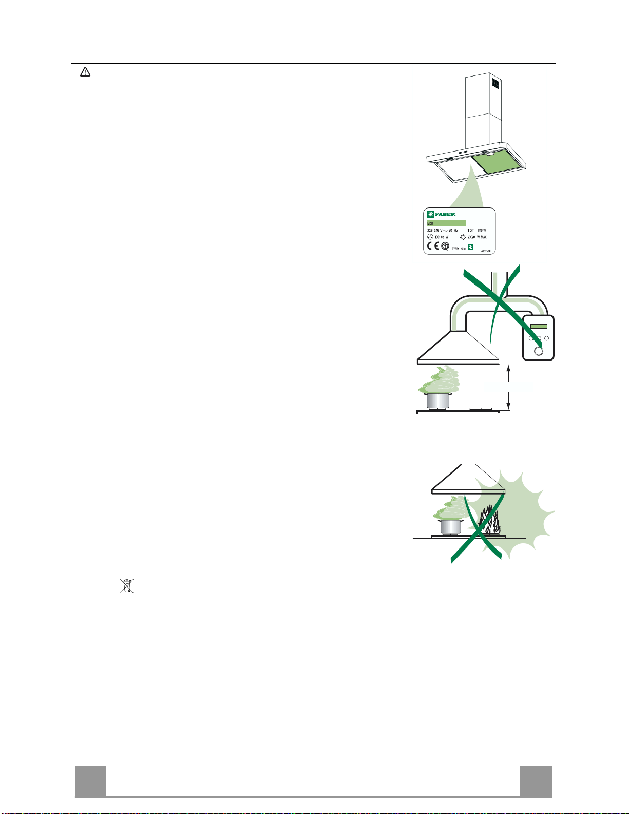
• The minimum safety distance between the cooker top and the extractor hood is 650
mm.
• Check that the mains voltage corresponds to that indicated on the rating plate fixed
to the inside of the hood.
• For Class I appliances, check that the domestic power supply guarantees adequate
earthing.
Connect the extractor to the exhaust flue through a pipe of minimum diameter 120
mm. The route of t he flue must be as s hor t as possible.
• Do not connect the extractor hood to exhaust ducts carrying combustion fumes
(boilers, fi r eplaces, etc.).
• If the extractor is used in conjunction with non-electrical appliances (e.g. gas burning appliances), a sufficient degree of aeration must be guaranteed in the room in
order to prevent the backflow of exhaust gas. The kitchen must have an opening
communicati ng directly wit h the open air in order to guarantee the entry of clean air.
USE
• The extractor hood has been designed exclusively for domestic use to eliminate
kitchen smells.
• Never use the hoo d f or purposes other t han for which it has ben design ed.
• Never leave high naked flames under the hood wh en it is in operation.
• Adjust the flame intensity to direct it onto the bottom of the pan only, making sure
that it does not engulf the sides.
• Deep fat fryers must be cont inuously monitored during use: ov er heated oil can burst
into flames.
• Do not flambè under the range hood; risk of fire
• This appliance is not intended for use by persons (including children) with reduced
physical, sensory or mental capabilities, or lack of experience and knowledge,
unless they have been given supervision or instruction concerning use of the appliance by a perso n responsible for their safety.
• Children should be supervised to ensure that t hey do not play wit h the appliance.
MAINTENANCE
• Switch off or unplug the appliance from the mains supply before carrying out any
maintenance work.
• Clean and/or repl ace the Filters after the spe cified time period.
• Clean the hood usi ng a damp cloth an d a neutral liquid detergent.
The symbol on the product or on its packaging indicates that this product may not be treated as
household waste. Instead it shall be handed over to the applicable collection point for the recycling
of electrical and electronic equipment. By ensuring this product is disposed of correctly, you will help
prevent potential negative consequences for the environment and human health, which could otherwise be caused by inappropriate waste handling of this product. For more detailed information about
recycling of this product, please contact your local city office, your household waste disposal service
or the shop where you purchased the product.
650 mm min.
Page 9
EN
9
9
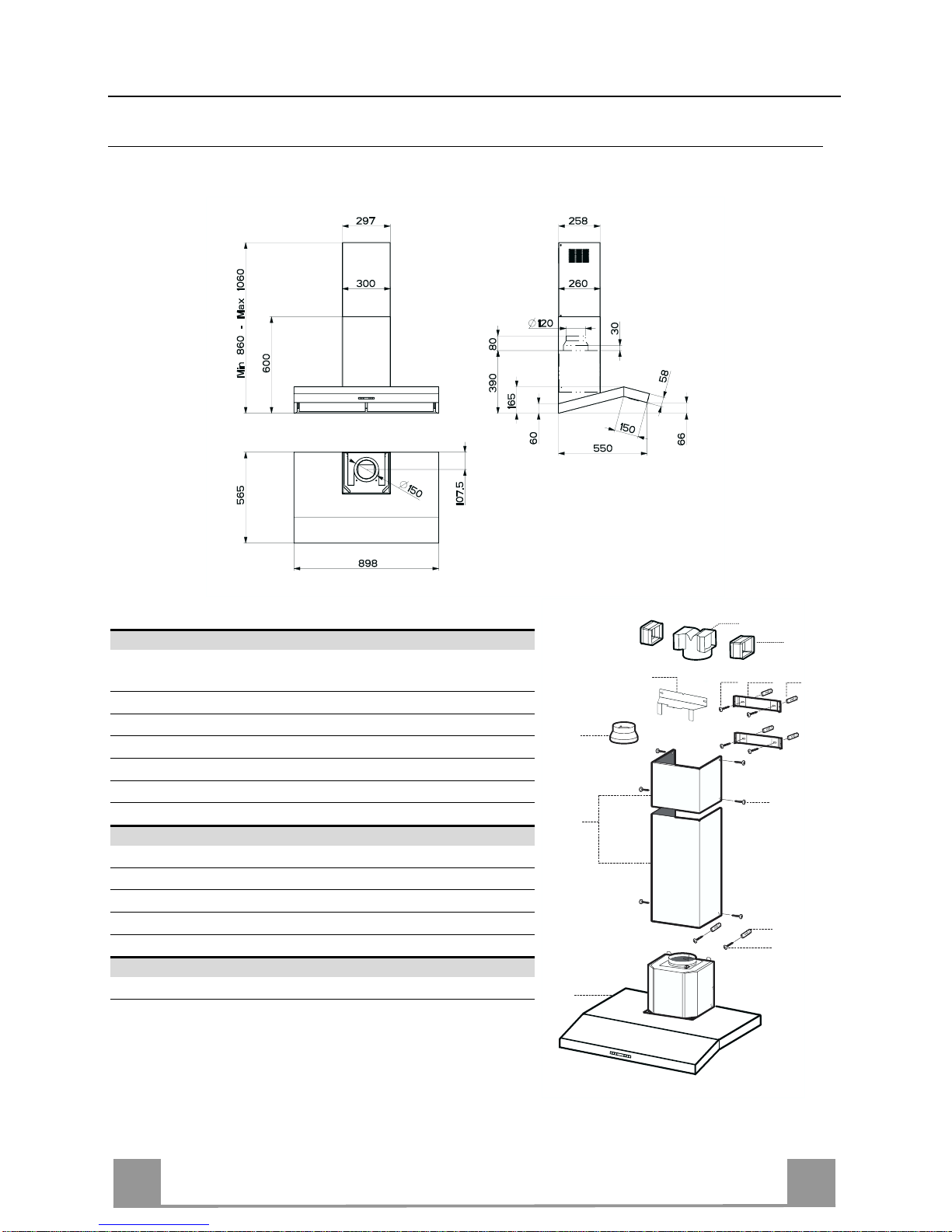
CHARACTERISTICS
Dimensions
Components
Ref. Q.ty Product Components
1 1 Hood Body, complete with: Controls, Light, Blower,
Filters
2 1 Telescopic Chimney comprising:
2.1 1 Upper Section
2.2 1 Lower Section
9 1 Reducer Flange ø 150-120 mm
14.1 2 Air Outlet Connecti on Extension
15 1 Air Outlet Connecti on
Ref. Q.ty Installation Components
7.2.1 2 Upper Chimney Section Fixing Brackets
7.3 1 Air Outlet Connecti on Support
11 6 Wall Plugs
12a 6 Screws 4,2 x 44,4
12c 6 Screws 2,9 x 9,5
Q.ty Documentation
1 Instruction Manual
14.1
15
2.1
2.2
2
12c
12a
7.2.1 11
11
12a
9
7.3
1
Page 10
EN
110
11
12a
400
X
116
1÷2
116
650 min.
7.2.1
7.3
INSTALLATION
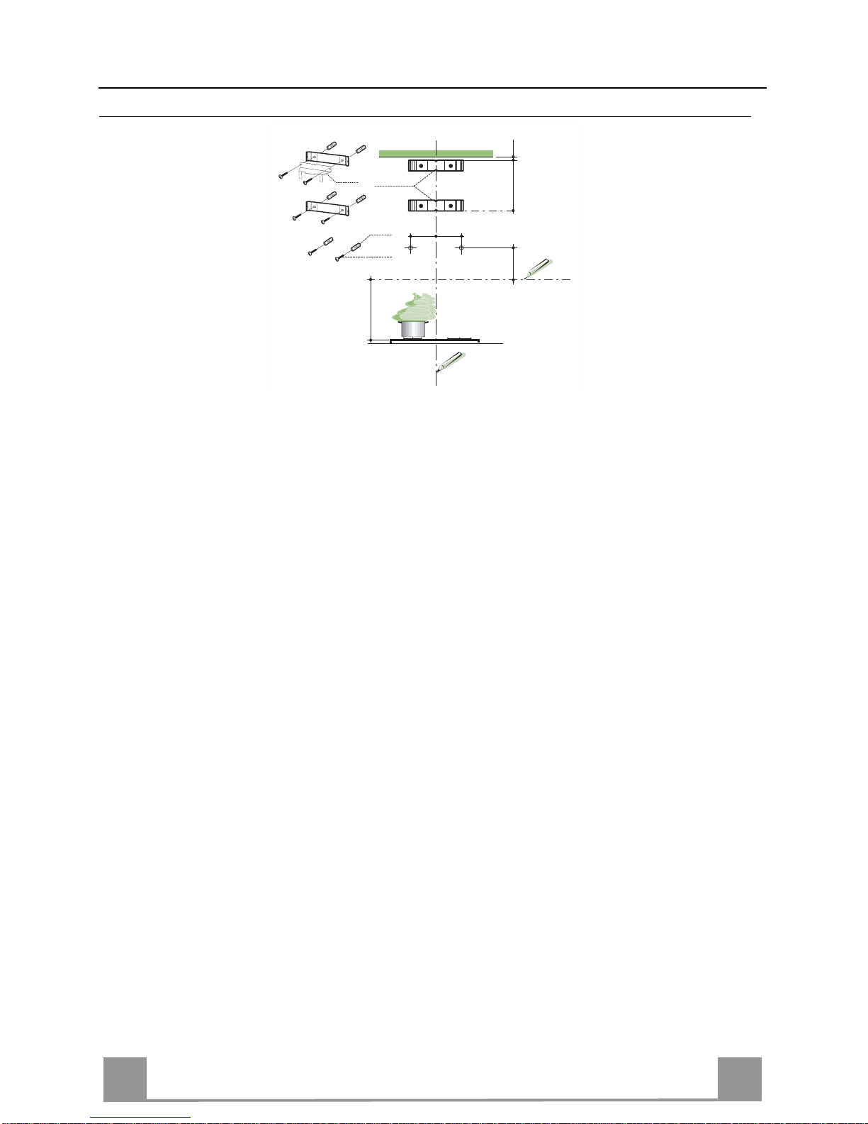
Wall drilling and bracket fixing
Wall marking:
• Draw a vertical line on the supporting wall up to the ceiling, or as high as practical, at the
centre of the area in which the hood will be installed.
• Draw a horizontal line at 650 mm above the hob.
• Place bracket 7.2.1 on the wall as shown about 1-2 mm from the ceiling or upper limit align-
ing the centre (n otch) with the vertical reference line.
• Mark the wall at the centres o f the h oles in the bracket.
• Place bracket 7.2.1 on the wall as shown at X mm below the first bracket (X = height of the
upper chimney section supplied), aligning the centre (notch) with the vertical line.
• Mark the wall at the centres of the ho les in the bracket.
• Mark a reference poi nt as indicated at 116 mm from the vertical referen ce line and 400 mm
above the horizontal reference line.
• Repeat this operation on the other side.
• Drill ø 8 mm holes at all the centre points marked.
• Insert the wall plugs 11 in the hole s.
• Fix the lower bracket 7.2.1 using the 12a screws (4,2 x 44,4) supplied.
• Fix the upper bracket 7.2.1 and the air outlet connection support 7.3 together using the 2
screws 12a (4,2 x 44,4) supplied.
• Insert the two screws 12a (4,2 x 44,4) supplied in the hood body fixing holes, leaving a gap
of 5-6 mm between the wall and the head of the screw.
Page 11
EN
111
Mounting the hood body
• Before attaching the hood body, tighten the two screws Vr located on the hood body mounting points.
• Hook the hood body onto the screws 12a.
• Fully tighten support screws 12a.
• Adjust screws Vr to level the hood body.
12a
Vr
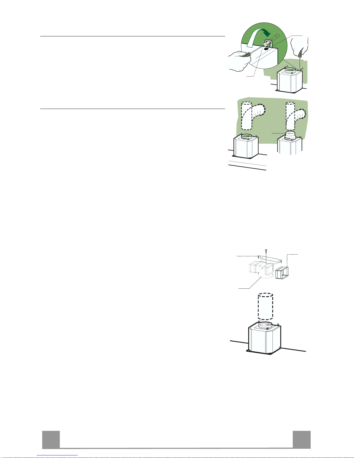
Connections
DUCTED VERSION AIR EXHAUST SYSTEM
When installing the ducted version, connect the hood to the
chimney using either a flexible or rigid pipe ø 150 or 120 mm,
the choice of which is left to the installer.
• To install a ø 120 mm air exhaust connection, insert the reducer flange 9 on the hood body outlet.
• Fix the pipe in position using sufficient pipe clamps (not supplied).
• Remove any activated charcoal filters.
9
ø 120ø 150
RECIRCULATION VERSION AIR OUTLET
• Insert the Co nnector 15 into th e Support bracket 7.3 and fix it
with a screw.
• Insert the connection extension pieces laterall y 14.1 in connection 15.
• M ake sure that the outlet of the extensio n pieces 14.1 is horizontally and vertically aligned with the chimney outlets.
• Connect the air outlet connection 15 to the hood body outlet
using either a flexible or rigid pipe ø 150 mm, the choice of
which is left to the installer.
• Ensure that the activated charcoal filters have been inserted.
ø 150
15
14.1
7.3
Page 12
EN
112
ELECTRICAL CONNECTION
• Connect the hood to the mains through a two-pole switch having a contact gap of at least 3 mm.
• Remove the grease filters (see paragraph Maintenance) being
sure that the co nnector of the feeding cable is correctly inserted
in the socket placed on the side of the fan.
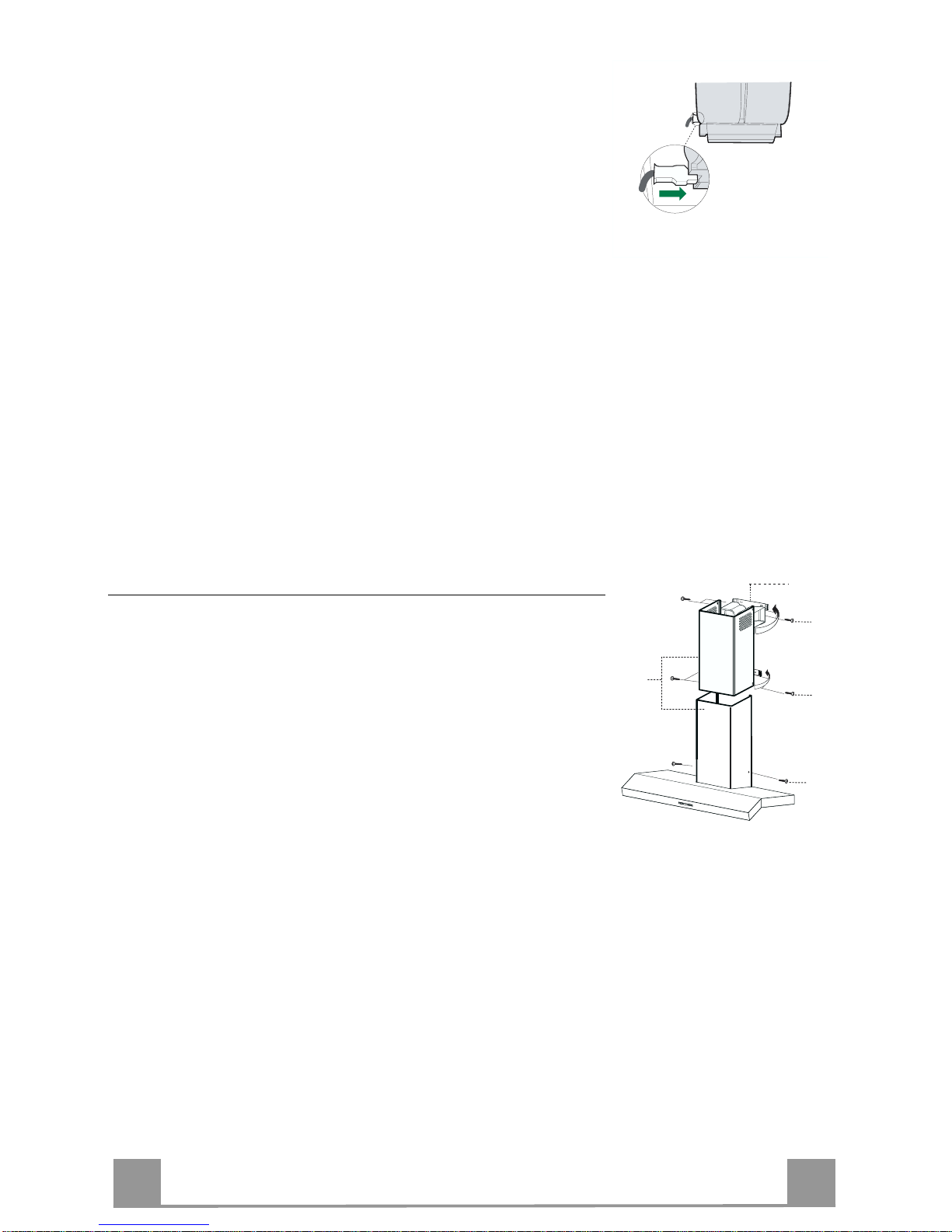
Flue assembly
Upper exhaust flue
• Slightly widen the two sides of the upper flue and hook them
behind the brackets 7.2.1, making sure that they are well
seated.
• Secure the sides to the brackets using the 4 screws 12c (2,9 x
9,5) supplied.
• Make sure that the outlet of the extensions pieces is aligned
with the chimney outlets.
Lower exhaust flue
• Slightly widen the two sides of the flue and hook them between the upper flue and the wall, making sure that they are
well seated.
• Fix the lower part laterally to the hood body using the 2 screws
12c (2,9 x 9,5) supplied.
12c
12c
12c
2.1
2.2
2
7.2.1
Page 13
EN
113
USE
T
1
T
2
T
3
T
4
T
5
L
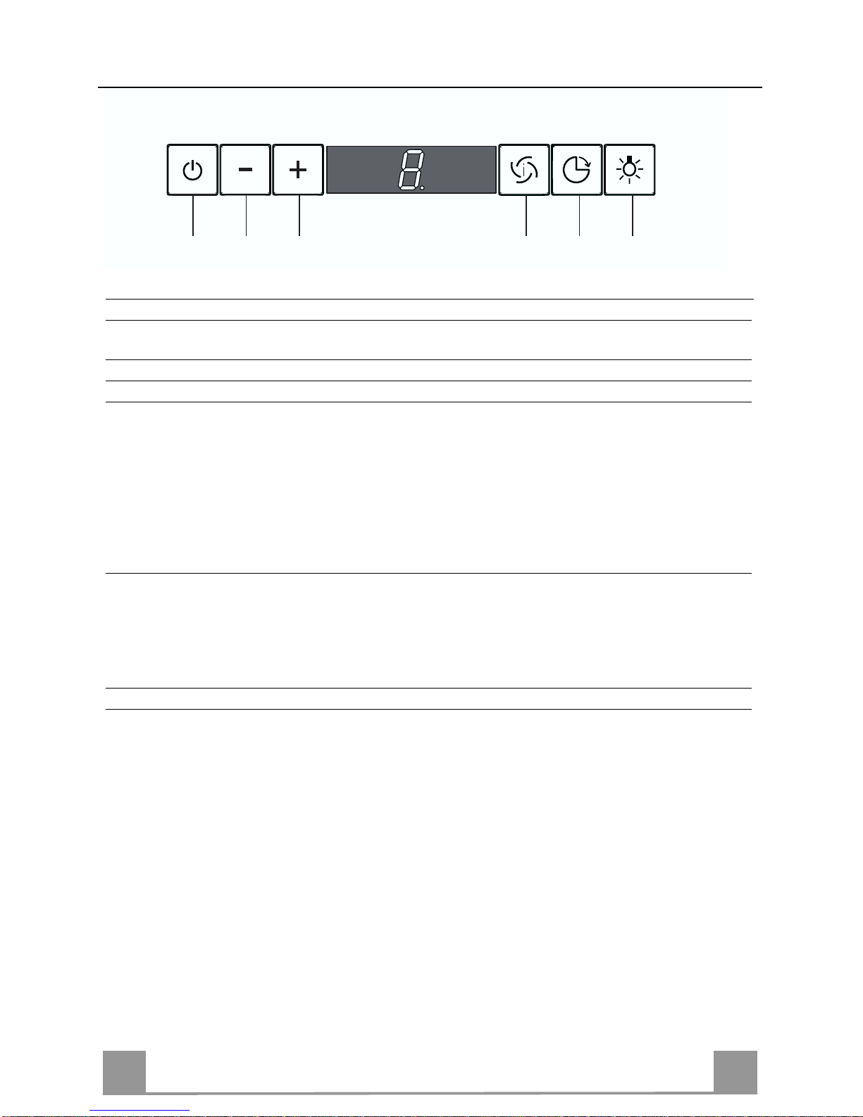
Control panel
TOUCH CONTROL FUNCTION
T1 ON/OFF Motor Switches the hood motor on and off. The latest selected
speed appears on the display.
T2 Speed - Decreases the suction speed: V3 → V2 → V1
T3 Speed + In creases the suction speed: V1 → V2 → V3
T4 Intensive speed Activates the inten sive speed from any previously select ed
speed. The intensive speed can be activated even when the
motor is OFF. By pressing the same touch control once again
or by switching off the motor this function can be deactivated. Intensive speed cannot be activated when the delay
function is on. Intensive speed has been timed at 10 minutes:
H appears on the display and a spot down on the right side
flashes once a second. After 10 minutes the system activates
automatically the lat est selected speed.
T5 Delay Activates and deactivates the delayed shutdown of the hood
(motor + lighting) at 30 minutes: the selected speed of the
hood appears on the display and a spot down on the right
side flashes once a second. By pressing the same touch control once again or by switching off the motor delay function
can be deactivated .
L Lighting Turns light on and off.
Page 14
EN
114
MAINTENANCE
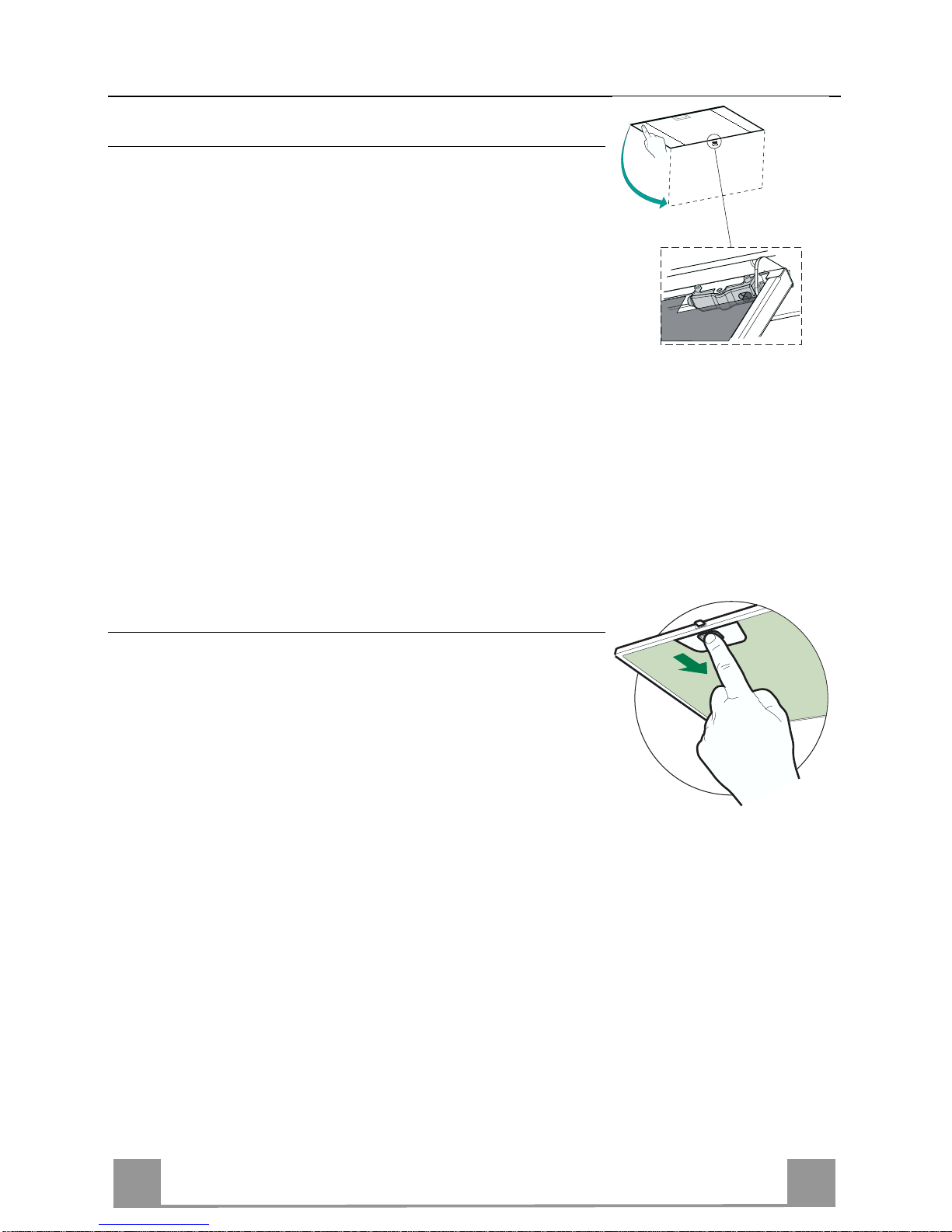
Cleaning the Comfort Panels
• Pull the Comfort Panel to open it.
• Disconnect the panel from the hood canopy by sliding the fixing pin lever.
• The comfort panel must never be washed in a dishwasher.
• Clean the outside using a damp cloth and neutral liquid detergent.
• Clean the inside as well using a damp cloth and neutral detergent; do not use wet cloths or sponges, or jets of water; do not
use abrasive substances.
• When the above operation has been completed, hook the panel
back to the hood canopy and close it by turning the knob in the
opposite direction .
Grease filters
CLEANING METAL SELF- SUPPORTIN G GREASE FILTERS
• The filters must be cleaned every 2 months of operation, or
more frequently for particularly heavy usage, and can be
washed in a dishwasher.
• Remove the filters one at a time by pushing them towards the
back of the group and pulling down at the same time.
• Wash the filters, taking care not to bend them. Allo w them to
dry before refitting.
• When refitting the filters, make sure that the handle is visible
on the outside.
Page 15
EN
115
Activated charcoal filter (Recirculation version)
REPLACING THE ACTIVATED CHARCOAL FIL T ER
• The filter is not washable and cannot be regenerated, and must
be replaced approximately every 4 months of operation, or
more frequently for particularly heavy usage.
• Remove the metal grease filters
• Remove the saturated activated carbon filter by releasing the
fixing hooks
• Fit the new filter by hooking it into its seating
• Replace the metal grease filters.
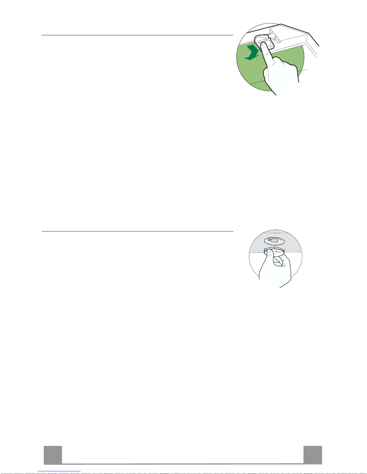
Lighting
LIGHT REPLACEMENT
20 W halogen light.
• Remove the snap-on lamp cover by levering it from under the
metal ring, supporting it with one hand.
• Remove the halogen lamp from the lamp holder by pulling
gently.
• Replace the lamp with a new one of the same type, making
sure that you insert the two pins properly into the housings on
the lamp holder.
• Replace the snap-on lamp cover.
Page 16

IT 116
CONSIGLI E SUGGERIMENTI
Questo libretto di istruzioni per l'uso è previsto per più versioni dell'apparecchio.
Possibile che siano descritti singoli particolari della dotazione, che non riguardano il
Vostro apparecchio.
INSTALLAZIONE
• Il produtto re declina qualsiasi re sponsabilità per dann i dovuti ad installa zione non
corretta o non conforme alle regole dell’arte.
• La distanza minima di sicurezza tra il Piano di cottura e la Cappa deve essere di
650 mm.
• Verificare che la tensione di rete corrisponda a quella riportata nella targhetta posta
all’interno della Cappa.
• Per Apparecchi in Classe Ia accertarsi che l’impianto elettrico domestico g arantis ca
un corretto sc ar ico a terra.
• Collegare la Cappa all’uscita dell’aria aspirata con tubazione di diametro pari o
superiore a 12 0 mm. Il percorso della tubazione deve essere il più breve possibile.
• Non collegare la Cappa a condotti di scarico dei fumi prodotti da combustione (caldaie, caminetti, ecc.).
• Nel caso in cui nella stanza vengano utilizzati sia la Cappa che apparecchi non
azionati da energia elettrica (ad esempio apparecchi utilizzatori di gas), si deve
provvedere ad una aerazione sufficiente dell’ambiente. Se la cucina ne fosse
sprovvista, praticare un’apertura che comunichi con l’esterno, per garantire il richiamo d’aria pulita.
USO
• La Cappa è stata progettata esclusivamente per uso domestico, per abbattere gli
odori della cucina.
• Non fare mai uso i mproprio dell a C appa.
• Non lasciare fiamme libere a fort e intensità sot to la Cappa in funz i one.
• Regolare sempre le fiamme in modo da evitare una evidente fuoriuscita laterale
delle stesse ri spetto al fondo delle pentole.
• Controllare le friggitrici durante l’uso: l’olio surriscaldato potrebbe infiammarsi.
• Non preparare alimenti flambè sot to la cappa da cucina; pericolo d'i ncendio.
• Questo apparecchio non deve essere utilizzato da persone (bambini inclusi) con
ridotte capacità psichiche, sensoriali o mentali, oppure da persone senza esperienza e conoscenza, a meno che non siano controllati o istruiti all’uso dell’apparecchio
da persone responsabili della loro sicurezza.
• I bambini devono essere supervisionati per assicurarsi che non giochino con
l’apparecchio.
MANUTENZIONE
• Prima di procedere a qualsiasi operazione di manutenzione, disinserire la Cappa
togliendo la spina elettrica o spegnendo l’interruttore generale.
• Effettuare u na sc rup o los a e tempestiva m anu te nz io ne dei Filtri secondo gli intervalli
consigliati.
• Per la pulizia delle superfici de lla Cappa è sufficien te utilizzare un panno u mido e
detersivo li quido neutro.
Il simbolo sul prodotto o sulla confezione indica che il prodotto non deve essere considerato
come un normale rifiuto domestico, ma deve essere portato nel punto di raccolta appropriato per il
riciclaggio di apparecchiature elettriche ed elettroniche. Provvedendo a smaltire questo prodotto in
modo appropriato, si contribuisce a evitare potenziali conseguenze negative per l’ambiente e per la
salute, che potrebbero derivare da uno smaltimento inadeguato del prodotto. Per informazioni più
dettagliate sul riciclaggio di questo prodotto, contattare l’ufficio comunale, il servizio locale di smaltimento rifiuti o il negozio in cui è stato acquistato il prodotto.
650 mm min.
Page 17

IT 117
CARATTERISTICHE
Ingombro
Componenti
Rif. Q.tà Componenti di Prodotto
1 1 Corpo Cappa completo di: Comandi, Luce, Gruppo
Ventilatore, Filtri
2 1 Camino T elescopico f ormato da:
2.1 1 Camino Superiore
2.2 1 Camino Inferiore
9 1 Flangi a di Riduzione ø 150-120 mm
14.1 2 Prolunga Raccordo Us cita Aria
15 1 Raccordo Uscita Aria
Rif. Q.tà Componenti di Installazione
7.2.1 2 Staffe Fissaggio Camino Superiore
7.3 1 Staffa Sostegno Raccordo
11 6 Tasselli
12a 6 Viti 4,2 x 44,4
12c 6 Viti 2,9 x 9,5
Q.tà Documentazione
1 Libretto Istruzioni
14.1
15
2.1
2.2
2
12c
12a
7.2.1 11
11
12a
9
7.3
1
Page 18

IT 118
11
12a
400
X
116
1÷2
116
650 min.
7.2.1
7.3
INSTALLAZIONE
Foratura Parete e Fissaggio Staffe
Tracciare sulla Parete:
• una linea Verticale fino al soffitto o al limite superiore, al centro della zona prevista per il
montaggio della Cappa;
• una linea Orizzontale a: 650 mm min. sopra il Piano di Cottura.
• Appoggiare come indicato la St affa 7.2.1 a 1-2 mm dal soffitto o dal limite superiore, allineando il suo centro (intagli) sulla linea Verticale di riferimento.
• Segnare i centri dei Fori della Staffa.
• Appoggiare co me indi cato la S taffa 7.2.1 a X mm sotto la pri ma staffa (X = altezza Camino
Superiore in dotazione), allineando il suo centro (intagli) sulla linea Verticale di riferimento.
• Segnare i centri dei Fori della Staffa.
• Segnare come indicato, un punto di riferimento a 116 mm dalla linea Verticale di riferimento, e 400 mm sopra la linea Orizzontale di riferimento.
• Ripetere questa operazione dalla parte opposta.
• Forare ø 8 mm i punti segnati.
• Inserire i tasselli 11 nei fori.
• Fissare la Staffa inferiore 7.2.1 ut iliz z ando le Vi ti 12a (4,2 x 44,4 ) in dotazione.
• Fissare insieme la Staffa superiore 7.2.1 e la Staffa sostegno rac cordo 7.3 utilizzando le 2
viti 12a (4,2 x 44,4) in dotazione.
• Avvitare 2 Viti 12a (4,2 x 44,4) in dotazione nei fori per il fissaggio del corpo Cappa, lasciando uno spazio di 5-6 mm fra la parete e la testa della vite.
Page 19

IT 119
Montaggio Corpo Cappa
• Prima di agganciare il Corpo Cappa, serrare le 2 Viti Vr situate
sui punti di aggancio del Corpo Cappa.
• Agganciare il Corpo Cappa alle Viti 12a.
• Serrare definitivamente le Viti 12a di supporto.
• Agire sulle Viti Vr per livellare il Corpo Cappa.
12a
Vr
Connessioni
USCITA ARIA VERSIONE ASPIRANTE
Per installazione in Versione Aspirante collegare la Cappa alla
tubazione di uscita per mezzo di un tubo rigido o flessibile di
ø150 o 120 mm, la cui scelta è lasciata all'installatore.
• Per collegamento con tubo ø120 mm, inserire la Flangia di riduzione 9 sull’Uscita del Corpo Cappa.
• Fissare il tubo con adeguate fascette stringitubo. Il materiale
occorrente non è in dotazione.
• Togliere eventuali Filtri Antiodore al Carbone attivo.
9
ø 120ø 150
USCITA ARIA VERSIONE FILTRANTE
• Inserire il Raccord o 15 nella Staffa di Sostegno 7.3 fissandolo
con una Vite.
• In serire lateralmente le P rolunghe Racco rdo 14.1 sul Raccordo
15.
• Assicurarsi che l’uscita delle Prolunghe Raccordo 14.1 risulti
in corrispondenza delle bocchette del Camino sia in orizzontale
che in verticale.
• Collegare il Raccordo 15 all’Uscita del Corpo Cappa per mezzo di un tubo rigido o flessibile di ø150 mm, la cui scelta è lasciata all'installatore.
• Assicurarsi della presenza del Filtro Antiodore al Carbone attivo.
ø 150
15
14.1
7.3
Page 20

IT 220
CONNESSIONE ELETTRICA
• Collegare la Cappa all’Alimentazione di Rete interponendo un
Interruttore bipolare con apertura dei contatti di almeno 3 mm.
• Rimuovere i Filtri antigrasso (vedi par. “Manutenzione”) e assicurarsi che il connettore del Cavo di alimentazione sia correttamente inserito nella presa dell’Aspiratore
Montaggio Camino
Camino superiore
• Allargare leggermente le due falde laterali, agganciarle dietro
le Staffe 7.2.1 e richiuderle fino a battuta.
• Fissare lateralmente alle Staffe con 4 Viti 12c (2,9 x 9,5) in
dotazione.
• Assicurarsi che l’uscita delle Prolunghe Raccordo risulti in corrispondenza delle boc che tte de l Camino.
Camino inferiore
• Allargare leggermente le due falde laterali del Camino, agganciarle tra il Camino superiore e la parete e richiuderle fino a
battuta.
• Fissare lateralmente la parte inferiore al Corpo Cappa, con 2
Viti 12c (2,9 x 9, 5) in dotazi one.
12c
12c
12c
2.1
2.2
2
7.2.1
Page 21

IT 221
USO
T
1
T
2
T
3
T
4
T
5
L
Quadro Comandi
TASTO FUNZIONI
T
1 ON/OFF Motore Attiva e arresta il motore d’aspirazione. Sul display viene
visualizzato lo step di velocità precedentemente impostat a.
T
2 Velocità - Decrementa la velocità del motore: V3 →V2 → V1
T3 Velocità + Incrementa la velocità del motore: V1→V2→ V3
T4 Velocità intensiva Attiva la velocità intensiva da qualsiasi velocità o da motore
spento.Per disin serirla basta premere d i nuovo lo stesso tasto
o spegnere il motore. L’intensiva non è attivabile se è attiva
la funzione Delay. La velocità intensiva è te mporizzata a 10
minuti: sul display viene visualizzato H e il punto in basso a
destra lampeggia una volta al secondo. Al termine dei 10 minuti il sistema torna au tomaticamen te alla veloci tà precedentemente impostata.
T
5 Delay Attiva e disattiva la modalità di arresto totale della cappa
(motore+luci) dopo 30 minuti: il display visualizza la
velocità del motore e il punto in basso a destra lampeggia
una volta al secondo. Per disabilitare il Delay si può
ripremere lo stesso tasto o ppure spegnere il motore
L Luci Accende e spegne le luci della cappa.
Page 22

IT 222
MANUTENZIONE
Pulizia dei Confort Panel
• Aprire il Confort Panel tirandolo.
• Sganciare il pannello dal corpo cappa facendo scorrere
l’apposita leva del perno di fissaggio.
• Il confort panel non va assolutamente lavato in lavastoviglie.
• Pulirlo esternamente con un panno umido e detersivo liquido
neutro.
• Pulirlo anche internamente utilizzando un panno umido e detergente neutro; non utilizzare panni o spugne bagnate, n é getti
d’acqua; non utilizzare sostanze abrasive.
• Ad operazione ultimata riagganciare il pannello al corpo cappa
e richiuderlo.
.
Filtri antigrasso
PULIZIA FILTRI ANTIGRASSO METALLICI AUTOPORTAN TI
• Sono lavabili anche in lavastoviglie, e necessitano di essere
lavati ogni 2 mesi circa di utilizzo o più frequentemente, per un
uso particolarmente intenso.
• Togliere i Filtri uno alla volta, spingendoli verso la parte posteriore del gruppo e tirando contempo raneamente verso il basso.
• Lavare i Filtri evitando di piegarli, e lasciarli asciugare prima
di rimontarli.
• Rimontarli facendo attenzione a mantenere la maniglia verso la
parte visibile esterna.
Page 23

IT 223
Filtro antiodore (Versione Filtrante)
SOSTITUZIONE FILTRO ANTIODORE AL CARBONE ATTIVO
• Non è lavabile e non è rigenerabile, va sostituito almeno ogni 4
mesi o più frequentemente, per un uso particolarmente intenso.
• Togliere i Filtri antigrasso metallici.
• Rimuovere il Filtro antiodore al Carbone attivo saturo, agendo
sugli appositi agganci.
• Montare il nuovo Filtro agganciandolo nella sua sede.
• Rimontare i Filtri antigrasso metallici.
Illuminazione
SOSTITUZIONE LAMPADE
Lampade alogene d a 20 W
• Togliere il bloccavetro metallico a pressione facendo leva sotto
la ghiera, sostenendolo con una man o.
• Estrarre la lampadina alogena d al portalampada.
• Sostituirla con una nuova lampadina di uguali caratteristiche,
facendo attenzione ad inserire correttamente i due spinotti nella
sede del portalampade.
• Rimontare il bloccavetro a pressione.
Page 24

FR
224
CONSEILS ET SUGGESTIONS
La présente notice d'emploi vaut pour plusieurs versions de l'appareil. Elle peut contenir des
descriptions d 'accessoires ne figurant pas dans votre appareil.
INSTALLATION
• Le fabricant dé c line toute responsabilité en cas de dommage dû à une in stallation non correcte ou non conforme aux règles de l’a rt.
• L a dist a nc e mini m ale de s éc urit é entr e l e pl an de c uiss on et la hot t e doi t êtr e d e 6 50 mm au
moins.
• Vérifier que la tensio n du s ecteur correspond à la valeur qui figure sur la plaquette apposée à
l’intérieur de la hotte.
• Pour les Appareils appartenant à la Ière Classe, veiller à ce que la mise à la terre de
l’installation élect rique do mestique ait été effe ctuée confo rmément aux nor mes en vigueur.
• Connecter la hotte à la sort ie d’air aspiré à l’aide d’une tuyau terie d’un diamèt re égal ou supérieur à 120 mm. Le parcours de la tuyauterie doit être le plus court possible.
• Eviter de connecter la hotte à des conduites d’évacuation de fumées issues d’une combustion tel que (Chaudière, cheminée, etc…).
• Si vous utilisez des appareils qui ne fonctionnent pas à l’électricité dans la pièce ou est installée la hotte (par exemple: des appareils fonctionnant au gaz), vous devez prévoir une aération suffisante du milieu. Si la cuisine en est dépourvue, pratiquez une ouverture qui communique avec l’extér ieur pour garantir l’infiltrat ion de l’air pur.
UTILISATION
• La hotte a été conç ue exclusivement pour l’ usage domestiq ue, dans le but d’ éliminer les
odeurs de la cuisine.
• Ne jamais utiliser abusivement la hotte.
• Ne pas laisser les flammes libres à forte intensité quand la hotte est en service.
• To ujours régl er les flammes de manière à éviter tout e sortie latér ale de ces d ernières par
rapport au f ond des marmites.
• Contrôler les friteuses lors de l’utilisation car l’huile surchauffée pou rrait s’enf lammer.
• Ne pas préparer d’aliments flambé s sous la hotte de cuisine : risque d’in cendie
• Cet appareil ne doit pas être utilisé par des personnes (y compris les enfants) ayant des
capacit és psychi ques, s ensori elles o u mental es rédui tes, ni p ar des p ersonne s n’ayan t pas
l’expérience et la connaissance de ce type d’appareils, à moins d'être sous le contrôle et la
formation de personnes responsables de leur sécurité.
• Les enfants doivent être surveillés pour s'assurer qu'ils ne jouen t pas avec l'appa reil.
ENTRETIEN
• Avant d e procé der à tout e opérati on d’e ntretie n, retirer la hotte en retiran t la fich e ou en actionnant l’interrupt eu r général.
• Effectuer un entretien scrupuleux et en temps dû des Filtres, à la cadence conseillée.
• Pour le nettoyage des surfaces de la hotte, il suffit d’utiliser un chiffon humide et détersif
liquide neutre.
Le symbole sur le produit ou son emballage indique que ce produit ne peut être traité comme déchet
ménager. Il doit plutôt être remis au point de ramassage concerné, se chargeant du recyclage du matériel
électrique et électronique. En vous assurant que ce produit est éliminé correctement, vous favorisez la
prévention des conséquences négatives pour l’environnement et la santé humaine qui, sinon, seraient le
résultat d’un traitement inapproprié des déchets de ce produit. Pour obtenir plus de détails sur le recyclage
de ce produit, veuillez prendre contact avec le bureau municipal de votre région, votre service d’élimination
des déchets ménagers ou le magasin où vous avez a cheté le produit.
650 mm min.
Page 25

FR
225
CARACTERISTIQUES
Encombrement
Composants
Réf. Q.té Composants de Produit
1 1 Corps Hotte équipé de:Comma ndes, Lumièr e, Groupe
Ventilateur,Filtres
2 1 Cheminée Télescopique formée de :
2.1 1 Cheminée Supérieure
2.2 1 Cheminée Inférieure
9 1 Flasque de Réduction ø 150-1 20 mm
14.1 2 Rallonge Raccord Sortie Air
15 1 Raccord Sortie Air
Réf. Q.té Composants pour l ’installation
7.2.1 2 Brides Fixation Cheminée Supérieure
7.3 1 Bride Support Raccord
11 6 Chevilles
12a 6 Vis 4,2 x 44,4
12c 6 Vis 2,9 x 9,5
Q.té Documentation
1 Manuel d’instructions
14.1
15
2.1
2.2
2
12c
12a
7.2.1 11
11
12a
9
7.3
1
Page 26

FR
226
11
12a
400
X
116
1÷2
116
650 min.
7.2.1
7.3
INSTALLATION
Perçage Paroi et Fixation Brides
Tracer sur la paroi:
• une ligne verticale allant jusqu’au plafond ou à la limite supérieure, au centre de la zone
prévue pour le montage de la hotte;
• une ligne horizontale à 650 mm min. au-dessus du plan de cuisson.
• Poser comme indiqué une bride 7.2.1 sur la paroi à 1-2 mm du plafond ou de la limite supérieure, en alignant son centre (découpes) sur la ligne verticale de repère.
• Marquer les centres des trous rainurés de la bride.
• Poser comme indiqué la bride 7.2.1 à X mm sous la première bri de (X = hauteu r cheminée
supérieure fournie), en alignant son centr e (découpes) sur la ligne verticale d e repère.
• Marquer les centres des trous rainurés de la bride.
• Marquer comme indiqué, un point de référence à 116 mm de la ligne verticale de repère, et
400 mm au-dessus de la ligne horizontale de repère.
• Répéter cette opération sur le côté opposé.
• Percer de ø 8 mm tous les points marqués.
• Insérer les chevilles 11 dans les trous.
• Fixer la bride inférieure 7.2.1 en utilisant les vis 12a (4,2 x 44,4) fournies.
• Fixer ensemble la bride supérieure 7.2.1 et le support 7.3 en utilisant les vis 12a (4,2 x 44,4)
fournies.
• Visser les 2 vis 12a (4,2 x 44,4) fournies dans les trous de fixation du corps hotte, en laissant
un espace de 5-6 mm entre le mur et la tête de la vis.
Page 27

FR
227
Montage Corps Hotte
• Avant d’accrocher le corps hotte, serrer les deux vis Vr situées
sur les points d’accro chage du corps hotte.
• Accrocher le corps hotte aux vis 12a prévues à cet effet.
• Serrer définitivement les vis 12a de support.
• Agir sur les vis Vr pour niveler le corps hotte.
12a
Vr
Branchements
SORTIE AIR VERSION ASPIRANTE
En cas d’install ation en version aspirante, brancher la ho tte à la
tuyauterie de sortie via un tube rigide ou flexible de ø 150 ou 120
mm, au choix de l’installateur.
• En cas de branchement avec un tube de ø120 mm, insérer le
flasque de réduction 9 sur la sortie du corps de la hotte.
• Fixer le tube par des colliers appropriés. Le matériau nécessaire n’est pas fourni.
• Retirer les éventuels filtres anti-odeur au charbon actif.
9
ø 120ø 150
SORTIE AIR VERSION FILTRANTE
• Placer le raccord 15 dans l’étrier de soutien 7.3 en le fixant
avec une vis.
• Insérer latéralement les rallonges raccord 14.1 sur le raccord
15.
• S’assurer qu e la sortie des rallonges r accord 14.1 se trouve au
niveau des bouches de la cheminée aussi bien en horizontal
qu’en vertical.
• Brancher le racco rd 15 à la sortie du corps de la hotte avec un
tube rigide ou flexible de ø 150 mm, selon le choix de
l’installateur.
• S’assurer de la présence des filtres anti-odeur au charbon actif.
ø 150
15
14.1
7.3
Page 28

FR
228
BRANCHEMENT ELECTRIQUE
• Branch er la hotte sur le secteur en interposant un interrupteur
bipolaire avec ouverture des contacts d’au moins 3 mm.
• Enlever les filtres à graisse (voir § "Entretien") et s'assurer que
le connecteur du câb le d 'alimentati on so it bi en bran ché dan s la
prise du diffuseur.
Montage Cheminée
Cheminée supérieure
• Elargir légèrement les deux bo rds latériaux, et les accrocher
derrières les brides 7.2.1 ; refermer
jusqu’à la butée.
• Fixer latéralement aux brides à l’aide des 4 vis
12c fournies.
• S’assurer que la sortie des rallonges raccord se trouve au niveau des bouches de la cheminée.
Cheminée inférieure
• Elargir légèrement les deux bords latériaux de la Cheminée et
les accrocher entre la Cheminée s upérieure et la paroi; refermer
jusqu’à la butée.
• Fixer latéralement la partie inférieure au corps
hotte, à l’aide des deux 2 vis 12c fournies.
12c
12c
12c
2.1
2.2
2
7.2.1
Page 29

FR
229
UTILISATION
T
1
T
2
T
3
T
4
T
5
L
Tableau des commandes
TOUCHE FONCTIONS
T1 ON/OFF Moteur Actionne et arrête le moteur d’aspiration. Sur l’afficheur est
visualisé le pas de la vitesse précédemment sélectionnée.
T2 Vitesse - Réduit la vitesse du moteur: V3 → V2 → V1
T3 Vitesse + Augmente la vitesse du moteur: V1 → V2 → V3
T4 Vitesse intensive Actionne la vitesse intensive en partant d’une vitesse quel-
conque ou lorsque le moteur est éteint. Pour la désactiver, il
suffit d’appuyer à nouveau sur la même touche qui a été utilisée ou d’éteindre le moteur. La vitesse intensive ne peut pas
être actionnée si la fonction Delay est active. La vitesse intensive est tempori sée sur 10 minut es: sur l’afficheur est visualisée l’inscription H et le point en bas à droite clignote
une fois par seconde. Lorsque 10 minutes se sont écoulées, le
système retourne automatiquement à la vitesse précédemment sélectionnée.
T5 Delay Actionne et désactive la modalité d’arrêt total de la hotte
(moteur+éclairage) ap rès 30 minutes: l’afficheu r visualise la
vitesse du moteur et le point en bas à droite clignote une fois
par seconde. Pour invalider la fonction Delay on peut appuyer à nouveau sur la même touche ou éteindre le moteur.
L Éclairage Allume et éteint l’éclairage de la hotte.
Page 30

FR
330
ENTRETIEN
Nettoyage des Confort Panel
• Ouvrir le Confort Panel, en tirant ce dernier.
• Décrocher le panneau du corps de la hotte, en faisant coulisser
le levier du goujon de fixation spécialement prévu.
• En aucun cas, le confort panel ne doit être lavé au lavevaisselle.
• Le nettoyer à l’extérieur à l’aide d’un chiffon humide et d’un
détergent liquide neutre.
• Le nettoyer également à l’intérieur, en utilisant un chiffon humide et un détergent neutre; ne pas utiliser des chiffons ou des
éponges mouillées, ni des jets d’eau; ne pas utiliser des substances abrasives.
• Lorsque l‘opération est achevée, accrocher à nouveau le panneau sur le corps de la hotte, puis le refermer, en tournant le
bouton dans le sens inverse par rapport à l’ouverture.
Filtres anti-graisse
NETTOYA GE FILTRES AN TI-GR AISSE M ETALLIQ UES AU TOPORTE URS
• Lavables au lave-vaisselle, ils doivent être lavés environ tous
les 2 mois d’emploi ou plus fréquemment en cas d’emploi particulièrement intense.
• Retirer les filtres l’un aprés l’autre, en les poussant vers la partie arrière du groupe et en tirant simultanément vers le bas.
• Laver les filtres en évitant de les plier et les laisser sécher avant
de les remonter.
• Remonter les filtres en veillant à ce que la poignée reste vers la
partie visible externe
Page 31

FR
331
Filtre anti-odeur (Version filtrante)
REMPLACEMENT FILTRE AU CHARBON ACTIF
• Ni lavable, ni régénérable, le remplacer au moins tous les 4
mois d’emploi ou plus fréquemment en cas d’emploi particulièrement intense.
• Retirer les filtres anti-graisse métalliques.
• Retirer le filtre anti-odeur au charbon actif colmaté, en agissant
sur les crochets prévu s à cet effet.
• Monter le nouveau filtre anti-odeur au charbon actif.
• Remonter les filtres anti-graisse métalliques.
Eclairage
REMPLACEMENT LAMPES
Lampe halogène de 20 W.
• Enlever le dispositif métallique de blocage du verre par encliquetage en exerçant une pression sous l’embout en le soutenant
d’une main.
• Extraire la lampe du support
• Remplacer la l ampe par une nouvelle a yant le mêmes car actéristiques, en pren ant soi n d'in sérer correct ement les d eux fiches
dans le support.
• Remonter le dispositif de blocage du verre par encliquetage.
Page 32

DE
332
EMPFEHLUNGEN UND HINWEISE
Diese Gebrauchsanleitung gilt für mehrere Geräte-Aus führungen. Es ist möglich, dass
einzelne Ausstattungsmerkmale beschrieben sind, die nicht auf Ihr Gerät zutreffen.
MONTAGE
• Das Gerät darf nur vom Fachpersonal angeschlossen werden.
• Der Herstel ler ha ftet nic ht für Sch äden, di e auf eine fehlerh afte un d unsach gemäß e Montage zurückzuführen sind.
• Der minimal e Sicherh eitsabstan d zwischen K ochmuld e und Hau be muss 650 m m betragen.
• Prüfen, ob die Netz spannung mit d em Wert auf d em im Haub eninneren ang ebrachten Schild übereinstimmt.
• Bei G er ät e n d er K l as s e I i st s i c her z ustellen, dass die elektri s c h e A nl a ge des Wohnhauses
über eine vorschriftsmäßige Erdung verfügt.
• Das Anschlussrohr der Haube zur Luftaustrittsöffnung sollte möglicherweise einen
Durchmesser von 150 mm aufweisen. Der Rohrverlauf muss so kurz wie möglich sein.
• Die Haube darf an keine Entlüftungsschächte angeschlossen werden, in die Verbrennungsgase (Heizkessel, Kamine usw.) geleitet werden.
• Werden im Raum außer der Dunstabzugshaube andere, nicht elektrisch betriebene (z.B.
gasbetrieb ene) Gerät e verwend et, m us s für eine ausreichende B el ü ftung gesorgt werden.
Sollte di e Küch e dies bez üglich nich t ents prech en, i st an ei ner A usse nwand eine Öffn ung
anzubringen, die Frischluftzufuhr g ew ähr leistet.
BEDIENUNG
• Die Dunstabz ugshau be ist aussc hließlic h zum Eins atz im priva ten Haush alt und zur B eseitigung v on Küchengerüchen vorgesehen.
• Bei unsachgemäßer Benutzung wird keine Haftung übernommen.
Achtung! Große Flammen bei eingeschalteter Haube niemals unbedeckt lassen.
• Die Intensivität der Flamme ist so zu regulieren, dass sie den Topfboden nicht überragt.
Achtung! Frittiergeräte müssen während des Gebrauchs stets beaufsichtigt werden: Überhitztes Öl kann sich entzünden.
• Keine flambierten Speisen unter der Abzugshaube zubereiten: Brandgefahr.
• Dieses Gerät darf nicht von Personen, auch Kindern, mit verminderten psychischen,
sensoris chen und gei stigern Fä higkei ten, oder von Person en ohne Erfa hrung un d Kenntnisse benutzt werden, sofern sie nicht von für ihre Sicherheit verantwortlichen Personen
beaufsichtigt und beim Gebrauch des Geräts angeleitet werden.
• Kinder d ürf en s ich nic ht unbe aufs ichti gt i n der Nä he d es Ger äts auf halt en u nd au f kei nen
Fall mit dem Gerät sp ielen.
WARTUNG
• Bevor Wartungsarbei ten durchgeführt werden, muss die Stromzufuhr z ur Haube unterbrochen wer de n, indem der Stecker gezoge n od er der Hauptschalter abgeschal tet wird.
• Bei der Fi lterwartung müss en die vom Herstel ler empfohlenen Z eiträume zum Aust auschen der Filter genauestens eingehalten werden.
• Zur Rei nigu ng der Hau benfläc hen Wir em pfehl en ei n feuc htes Tuch und ein mi ldes Flüssigreinigungsmittel.
• Bitte keine Reinigungsmittel mit Scheuermittel verwenden. Die Oberfläche wird damit
verkratzt.
Das Symbol auf dem Produkt oder seiner Verpackung weist darauf hin, dass dieses Produkt nicht als
normaler Haushaltsabfall zu behandeln ist, sondern an einem Sammelpunkt für das Recycling von elektrischen und elektronischen Geräten abgegeben werden muss. Durch Ihren Beitrag zum korrekten Entsorgen
dieses Produkts schützen Sie die Umwelt und die Gesundheit Ihrer Mitmenschen. Umwelt und Gesundheit
werden durch falsches Entsorgen gefährdet. Weitere Informationen über das Recycling dieses Produkts
erhalten Sie von Ihrem Rathaus, I hrer M ül labfuhr oder dem Geschäft, in dem Sie das Produkt gekauft haben.
650 mm min.
Page 33

DE
333
CHARAKTERISTIKEN
Platzbedarf
Komponenten
Pos. St. Produktkomponenten
1 1 Haubenkörper mit Schaltern, Beleuchtung, Gebläse-
gruppe, Filter
2 1 Teleskopkamin bestehend aus:
2.1 1 oberer Kaminteil
2.2 1 unterer Kaminteil
9 1 Reduzierflansch ø 150-12 0 mm
14.1 2 Verlängerung Luftaustritt-Anschlussstück
15 1 Luftaustritt-Anschlussstück
Pos. St. Montagekomponenten
7.2.1 2 Befestigungsbügel oberer Kaminteil
7.3 1 Bügel für Anschlusshalter
11 6 Dübel
12a 6 Schrauben 4,2 x 44,4
12c 6 Schrauben 2,9 x 9,5
St. Dokumentation
1 Bedienungsanleitung
14.1
15
2.1
2.2
2
12c
12a
7.2.1 11
11
12a
9
7.3
1
Page 34

DE
334
11
12a
400
X
116
1÷2
116
650 min.
7.2.1
7.3
MONTAGE
Bohren der Befestigungslöcher und Fixieren der Befestigungsbügel
Achtung: Bitte beachten Sie bei der Montage das Gewicht der kompletten Haube. Die Tragfä-
higkeit der Decke oder alternativ der Trägerplatte für diese Zugbelastung muss vor der Montage geprüft und gegebenenfalls durch die Anbringung von geeigneten Befestigungs- oder
Stabilisierungselementen hergestellt werden. Kann eine hinreichende Tragfähigkeit nicht sichergestellt werden, ist von einer Montage abzusehen.
Nachstehende Lin ien an die Wand zeichnen:
• eine vertikale Linie bis zur Decke oder oberen Begrenzung, und zwar in der Mitte des Bereiches, in dem die Haube montiert werden soll;
• eine horizontale Linie mit einem minimalen Abstand von 650 mm zur Kochfläche.
• Einen Bügel 7.2.1 zirka 1-2 mm unter der Decke od er oberen Begrenzung an die Wan d legen und seinen Mittelpunkt (Einschnitte) auf die vertikale Bezugslinie ausrichten.
• Die Mitte der beiden Bügellöcher an der Wand markieren.
• Den zweiten Bügel 7.2.1 an die Wand legen, wobei ein Abstand X mm vom oberen Bügel
einzuhalten ist (X = Höhe des jeweiligen oberen Kaminteils); den Mittelpunkt (Einschnitte)
auf die vertikale Bezugsl inie ausrichten.
• Die Mitte der Bügellöcher an der Wand markieren.
• Wie beschrieben einen Bezugspunkt 116 mm von der vertikalen Bezugslinie und 400 mm
oberhalb der horizontalen Bezugslinie kennzeichnen.
• Gleichermaßen an der gegenüberliegenden Seite vorgehen.
• Mit einem Bohrer ø 8 mm die markierten Punkte bohren.
• Die Dübel 11 in die Bohrungen einfügen.
• Den unteren Bügel mit den mitgelieferten Schrauben 12a (4,2 x 44,4) fixier en.
• Den Bügel für Anschlusshalter mit den 2 mitgelieferten Schrauben 12a (4,2 x 44,4) auf den
oberen Bügel 7.2.1 befestigen.
• 2 der mitgelieferten Schrauben 12a (4,2 x 44,4) bei den Befestigungslöchern des Haubenkörpers einschrauben, wobei zwischen Wand und Schraubenkopf ein Freiraum von 5-6 mm
zu belassen ist.
Page 35

DE
335
Montage des Haubenkörpers
• Bevor der Haubenkörper eingehakt wird, die 2 Schrauben Vr
bei den Haubenkörper-Anhakpunkten festziehen.
• Den Haubenk ör pe r be i de n Sc hraube n 12a e i nhä ng e n.
• Die Halteschrauben 12a definitiv festziehen.
• Den Haubenkörper mit Hilfe der Schrauben Vr ausrichten.
12a
Vr
Anschluss der Abluftversion
Bei Abluftbetrieb kann die Haube vom Installateur wahlweise
mittels Rohr oder Schlauch (ø 150 oder 120 mm) an die Außenrohrleitung angeschlossen werden.
• Bei Verwendung eines Anschlussrohres ø 120 den Reduzierflansch 9 am Haubenaustritt anbringen.
• Das Rohr mit geeigneten Rohrschellen fixieren. Das hierzu
erforderliche Material wird nicht mitgeliefert.
• Eventuell vorhandene Aktivkohlefilter entnehmen.
Achtung! Alle Q uerschnittänderungen oder Richt ungsän-
derunge n des A bluftka nals r eduzier en die L eistu ng der H aube.
9
ø 120ø 150
Anschluss der Umluftversion
• Den Anschluss 15 am Haltebügel 7.3 einset zen und mit einer
Schraube fixieren.
• Die Verl ängeru ngen 14.1 beim Anschluss 15 seitlich einfügen.
• Überprüfen, ob die Verlän gerungen 14.1 mit den entsprechenden Kaminstutzen sowohl horizontal wie auch vertikal übereinstimmen.
• V om Installateur wahlweise mittels Rohr oder Schlauch (ø 150
mm), den Anschluss 15 am Haubenaustritt anbringen.
• Kontrollieren, ob der Aktivkohle-Geruchsfilter montiert ist.
ø 150
15
14.1
7.3
Page 36

DE
336
Elektroanschluss
Vor der Installation die Netzspannung durch herausdrehen der
Sicherung oder ausschalten d es Hauptschalters stromlos machen.
• Bei Anschluss der Haube an das Stromnetz muss ein
zweipoliger Schalter mit einem Öffnungsweg von
mindestens 3 mm zwischengeschaltet werden.
• Entfernen Sie die Fettfilter (s. Abschnitt „Wartung“) und
versichern Sie sich, daß die Kabelverbindung in die Steckdose des Gebläses einwan dfrei eingesteckt wird.
Achtung: Das Gerät nur an die Netzspannung die im Typen-
schild angege ben ist anschl ießen.
Kaminmontage
Oberer Kaminteil
• Die beiden seitlichen Schenkel leicht auseinanderbiegen, hinter
den Bügeln 7.2.1 einhängen und bis zum Anschlag wieder
schließen.
• Bei den Bügeln 7.2.1 mit Hilfe der 4 mitgelieferten Schrauben
12c fixieren.
• Überprüfen, ob die Verlängerungen mit den entsprechenden
Kaminstutzen üb ereinstimmen.
Unterer Kaminteil
• Die beiden seitlichen Schenkel des Kaminteils leicht auseinander biegen, zwischen dem oberen Kaminteil und der Wand
einhängen und bis zum Anschlag wieder schließen.
• Den unteren Teil seitlich am Haubenkörper mit 2 der mitgelieferten Schrauben 12c fixieren.
12c
12c
12c
2.1
2.2
2
7.2.1
Page 37

DE
337
BEDIENUNG
T
1
T
2
T
3
T
4
T
5
L
Bedienfeld
TASTE FUNKTIONEN
T1 Motor ON/OFF Schaltet den Gebläsemotor ein und aus. Auf dem Display wird die
zuvor eingestellte Geschwindigkeitsstufe angezeigt.
T2 Geschwindigkeit - Erhöht die Geschwindigkeit des Motors: V3 → V2 → V1
T3 Geschwindigkeit + Verringert die Geschwindigkeit des Motors: V1 → V2 → V3
T4 Intensivstufe Aktiviert die Intensivstufe von jeder Geschwindigkeitsstufe aus
oder bei ausgeschaltetem Motor. Zum Ausschalten einfach die selbe Taste erneut drücken oder den Motor ausschalten. Bei aktivierter Delay-Funktion lässt sich die Intensivstufe nicht aktivieren. Die
Intensivstufe dauert 10 Minuten: Auf dem Display wird H angezeigt und der Punkt unten rechts blinkt einmal pro Sekunde. Nach
10 Minuten kehrt das System automatisch in die zuvor eingestellte
Geschwindigkeitsstufe zurück.
T5 Delay Aktiviert und deaktiviert den Modus Komplettes Ausschalten der
Haube (Motor + Beleuchtung) nach 30 Minuten: Auf dem Display
wird die Geschwindigkeitsstufe des Motors angezeigt und der
Punkt unten rechts blinkt einmal pro Sekunde. Zum Deaktivieren
der Delay-Funktion die selbe Taste erneut drücken oder den Motor
ausschalten.
L Beleuchtung Schaltet die Beleuchtung der Haube ein und aus.
Page 38

DE
338
WARTUNG
Reinigung der Comfort Panel
• Den Comfort Pane l durc h Zie hen öffnen.
• Die Platte vom Haubenkörper aushaken, indem der Hebel des
Befestigungsstiftes verschoben wird.
• Die Comfort Panel darf keinesfalls im Geschirrspüler gewaschen werden.
• Außen mit einem feuchten Lappen und neutralem Flüssigreiniger säubern.
• Innen mit einem feuchten Lappen und neutralem Reinigungsmittel säubern; keine nassen Lappen oder Schwämme oder
Wasserstrahl verwenden; kein Scheuermittel verwenden.
• Am Ende die Platte wieder am Haubenkörper einhaken und
schließen, indem der Drehknopf in die dem Öffnen entgegengesetzte Richtung gedreht wird.
Fettfilter
SELBSTTRAGENDER ME TALLFETTFILTER REINIGUNG
• Sie müssen nach 2-monatigem Betrieb bzw. bei starkem Einsatz auch häufiger gereinigt werden, was im Geschirrspüler
möglich ist.
• Die Filter nacheinander aushaken, indem sie auf die Rückseite
der Gruppe geschoben und gleichzeitig nach unten gezogen
werden.
• Die Filter reinigen (darauf achten, sie nicht zu verbiegen) und
vor der Remontage trocknen lassen.
• Bei der Remontage ist darauf zu achten, dass sich der Griff auf
der sichtbaren Außenseite befindet.
Page 39

DE
339
Geruchsfilter (Umluftversion)
AUSTAUSCHEN DER AKTIVKOHLE FIL TER
• Dieser Filter kann weder gewaschen noch wiederverwendet
werden und ist alle 4 Betriebsmonate bzw. bei starkem Einsatz
auch häufiger auszutauschen.
• Die Metallfettfilter entfernen.
• Den gesättigten Aktivkohle-Geruchsfilter aushaken.
• Den neuen Filter in seinem Sitz einhaken.
• Die Metallfettfilter wieder montieren.
• Die Kohlefilter können mit dem Hausmüll entsorgt werden.
Beleuchtung
AUSWECHSELN DER LAMPEN
Halogenlampe 20 W
• Vor dem Auswechseln der Lampen, die mittels Eindrücken
befestigte Glashalterung aus Metall durch Anheben der Zwinge
entfernen und die Halterung dabei mit einer Hand stützen.
• Die Lampe aus der Halterung nehmen.
• Die Lampe durch eine gleichwertige ersetzen und bei der Remontage darauf achten, daß die beiden Steckerstifte vorschriftsmäßig in die Lampenfassung eingeführt werden.
• Die Glashalterung wieder eindrücken.
Page 40

TR
440
TAVSIYELER VE ÖNERILER
Bu kullanma talimatι birden fazla c ihaz modeli i
çin geçerlidi r.
Cihazιnιza uymayan bazι donanιm özellikleri tarif edilmiş olabilir.
MONTAJ
• Yalnιş veya e ksik mo nta jda n doğan he rhang i b ir zara rιn sorumluluğu üreticiye ait
değildir.
• Davlum baz ile pişirici cihazιn ocak kιsmι arasιndaki minimum güvenlik mesafesi
650 mm.dir.
• Besleme voltajιnιn, davlumbaz içerisine yerleştirilen bilgi etiketinde belirtilenle
aynι olup olmadιğιnι kont rol edin.
• Sιnιf I elektrikli aletleri için, güç kaynağιnιn yeterli topraklamayι sağlayιp
sağlamadιğιnι kontrol edin. Minimum 120 mm çapιnda bir boru yoluyla
davlumbazι çιkιş bacasιna bağlayιn. Baca bağl ant ιsι mümkün oldu- ğunca kιsa
olmalιdιr.
• Davlumbaz borusunu yanιcι duman taşιyan baca de l iğine (buhar kazanι, şömine,
vb.) bağlamayιn.
• Davlumbazιn elektrikle çalιşmayan aletlerle (örneğin; gazlι cihazlar) bağιntιlι ola-
rak kullanιlmamasι halinde çιkιş gazιnιn geri tepmesini önlemek amacιyla odada
yeterli bir havalandιrma sağlanmalιdιr. Temiz hava girişini temin e tmek için mut-
fakta doğruda n dιşar ιya açιlan bir açιklιk bulunmal ιdιr.
KULLANIM
• Davlumbaz mutfaktaki kokularιn emilmesi amacιyla evlerde kullanιm için
tasarlanmιştιr.Ticari v e endüs tr iyel amaç lar içi n kull anmay ιnιz.
• Davlumbazι tasarlandιğι amaçlarιn dιşιnda kesinlikl e kull anmayιnιz.
• Davlumbaz çalιşιrken altιnda kesinlikl e yüksek çιplak ateş bιrakmayιn.
• Alev yoğunluğunu doğrudan tencerenin altιnda kalacak şekilde ayarlayιn,
kenarlarιnι sarmadιğιndan emin olun.
• Yağda kιzartma tavalarιnι kullanιrken sürekli olarak takip edin: fazla ιsιnan yağ
tutuşabilir.
• Kapağın altında kıvı lcı mdan ka çı nın, y angın r isk i
• Bu alet, güvenliklerinden sorumlu kişiler tarafından kontrol edilmedikleri veya
eğitilmedikleri sürece; fiziksel, duyumsal ve zihinsel kapasitesinde kısıtlama olan
(çocuklar dahil) veya aleti kullanma tecrübesi ve bilgisi olmayan kişiler tarafından
kullanılamaz.
• Bebeklerin, al etl e oynamadı k lar ından e mi n olmak i çi n kontr ol edil meli gerek i r.
BAKIM
• Herhangi bir bakιm işlemini gerçekleştirmeden önce davlumbazι kapatιn veya
fişini çιkarιn.
• Filtreleri bel irtil en zamanl ard a t emiz ley in v e / v eya de ğiştirin.
• Cihazι nemli bir bez ve nöt r bir sιvι deterjan k ullanar ak temi zl eyin.
Ürün vey a pak eti üz erin deki sembolü , bu ür ünü n norm al bir evs el atık olar ak g örülm em esi
ve bu tip elektr ikli v eya elektr onik ci hazlar ın atıl dığı dönüşümlü toplam a n oktal arı na t erke dilm esi
gerektiğine işaret eder. Bu ürünü ger ek ti ği gibi el i mi ne e tm e kural l arı n a uy ars anı z çev r e ve ins an
sağlığı üzerindek i olumsuz etk ilerini bert araf etmey e katkı sağlamış olursunuz. Bu ürünün geri
dönüşüm koşulları hakkında daha ayrıntılı bilgi için hudutları içinde bulunduğunuz belediyenin
ilgili diaresine, atık yoketme servisine veya ürünün sat ıcısına danışınız.
650 mm min.
Page 41

TR
441
ÖZELLIKLER
Boyutlar
Parçalar
Ref. Adet Ürünün parçaları
1 1 Şunlardan oluşan davlumbaz gövdesi: Kumandalar,
Lamba, Fan grubu, Filtreler
2 1 Şunlardan oluşan teleskopik baca:
2.1 1 Üst baca
2.2 1 Alt baca
9 1 Redüksiyon Flanşı ø 150-120 mm
14.1 2 Hava Çıkışı Uzatma Rakoru
15 1 Hava Çıkışı Rakoru
Ref. Adet Montaj Parçaları
7.2.1 2 Üst Baca Tesbit Braketleri
7.3 1 Rakor Destek Braketi
11 6 Dübeller
12a 6 Vidalar 4,2 x 44,4
12c 6 Vidalar 2,9 x 9,5
Adet Belgeler
1 Talimat Kılavuzu
14.1
15
2.1
2.2
2
12c
12a
7.2.1 11
11
12a
9
7.3
1
Page 42

TR
442
11
12a
400
X
116
1÷2
116
650 min.
7.2.1
7.3
MONTAJ
Duvarın Delinmesi ve Braketlerin Sabitlenmesi
Duvara şunları çiziniz:
• Tavana yada üst sınıra kadar uzunan Dikey bir çizgi: Davlumbazın monte edileceği yerin
tam merkezinden geçmelidir;
• Tezgâh (setüstü ocak) yüzeyin den 650 mm mesafeden geçen bir Yatay çizgi.
• Gösterildiği gibi Braketi 7.2.1 tavandan 1-2 mesafeye dayayınız ve bunun merkezini (çen-
tik) Dikey referans çizgisine hizalayınız.
• Braketin deliklerinin ortasından işaret koyunuz.
• Gösterildiği gibi Braketi 7.2.1 ilk braketin altına ve bundan X mesafeye dayayınız (X = Üst
Bacanın boyu) ve bun un merkezini (çentik) Dikey referans çizgisine hizalayınız.
• Braketin deliklerinin ortasından işaret koyunuz.
• Gösterildiği gibi Dikey referans çizgisinden 116 mm mesafeye, Yatay referans çizgisinin de
400 mm üzerine gelec ek şekilde bir referans deliği işaretleyiniz.
• Bu işlemi diğer taraftan da tekrar ediniz.
• İşaretlenen yerlere ø 8 mm çapında delikler açınız.
• Dübelleri (11) deliklere yerle ştiriniz.
• Cihaz donanımında verilen vidaları 12a (4,2 x 44,4 ) kullanarak alt Braketi 7.2.1
sabitleyiniz.
• Üs Braket 7.2.1 ile rakor destek Braketini 7.3 cihaz donanımında verilen 2 adet vidayı 12a
(4,2 x 44,4 ) kullanarak birlikte sabitleyiniz.
• Davlumbaz gövdesinin sabitlenmesi için, açılan deliklere donanımdaki 2 adet vidayı 12a
(4,2 x 44,4) takıp, sıkınız ve vidanın kafası ile duvar arasında 5-6 mm’lik bir mesajfe bırakınız.
Page 43

TR
443
Davlumbaz Gövdesi Montajı
• Davlumbaz Gövd esini kancalara t akmadadan önce gövde ü zerindeki kancalama noktalarında bulunan 2 adet vidayı Vr sıkınız.
• Davlumbaz Gövdesini vidalara 12a takınız.
• Destek vidalarını 12a nihai olarak sıkınız.
• Vr vidalarına müdahale ederek Davlumbaz Gövdesi seviyesini
hizalayınız.
12a
Vr
Bağlantılar
ASPİRATÖRLÜ MODEL HAVA ÇIKIŞI
Aspiratörlü modelin montajı için, davlu mbaz, montörü n seçeceği
150 yada 120 mm çapında sert veya esnek bir boru ile çıkış kanalına bağlanmalıdır.
• ø120 mm çapında boru ile bağlantı için, redüksiyon flanşını (9)
davlumbaz gövd esi çıkışına yerleştiriniz.
• Boruyu uygun kelepçelerle sıkarak sabitleyiniz. Bu malzeme
davlumbaz donanımıyla birlikte verilmemiştir.
• Varsa aktif karbonlu koku alma filtrelerini çıkarınız.
9
ø 120ø 150
FİLTRELİ MODELİN HAVA ÇIKIŞI
• Soketi 15 Destek mesnedine 7.3 yerleştirin ve bir vida ile
sabitleyin.
• Rakor Uzantılarını 14.1 diğer Rakora takı nız 15.
• Rakor Uzantıları çıkışının 14.1 hem dikey hem yatay planda
Baca ağızlarına denk gelmesine dikkat ediniz.
• Rakoru 15 montö rün seçec eği sert yada esnek 150 mm çapında
bir boru ile Davlumbaz Gövdesi Çıkışına bağlayınız.
• Aktif Karbonlu Koku Filtresinin mevcut olduğundan emin olunuz.
ø 150
15
14.1
7.3
Page 44

TR
444
ELEKTRİK BAĞLANTISI
• Davlumbazı şebeke cere yanına bağlarken aray temas aralığı en
az 3 mm olan çift kutuplu bir elektrik anahtarı koyunuz.
• Yağ tutucu filtreleri çıkarınız (bakınız "Bakım" paragrafı) ve
besleme kablosu soketinin aspiratör prizine iyice takılmış olduğundan emin olunuz.
Bacanın Montajı
Üst Baca
• İki yan kenarı hafifçe açınız, bunları braketlerin 7.2.1 arkasına
geçiriniz ve tam dayanana kadar tekrar kapatınız.
• Cihaz donanımında verilen 4 adet vidayla 12c (2,9 x 9,5) yan
taraflarından brake tlere sabitley iniz .
• Rakor uzantılarının çıkışının baca ağızlarına denk gelmesine
dikkat ediniz.
Alt Baca
• Bacanın iki yan kenarını hafifçe a çı nız, Üst baca ile duvar arasına geçirip tam dayanana kadar kapatınız.
• Cihaz donanımında verilen 2 adet vidayla 12c (2,9 x 9,5) alt
tarafını davlumbaz gövdesine sabitleyiniz.
12c
12c
12c
2.1
2.2
2
7.2.1
Page 45

TR
445
KULLANIM
T
1
T
2
T
3
T
4
T
5
L
Kumanda Tablosu
TUŞ FONKSİYONLARI
T1 Motor ON/OFF Aspiratör motorunu açar-kapatır. Ekranda daha önce ayar-
lanmış olan hız kademesi görüntüye gelir.
T2 Hız - Motorun hızını kademeli olarak azaltır: V3 → V2 → V1
T3 Hız + Motorun hızını kademeli olarak arttırır: V1 → V2 → V3
T4 Yoğun Hız Herhangi bir hızdayken, ya da motor kapalı iken yoğun hızı
devreye alır. Devr eden çıkarmak için aynı tuşa yeniden basmak ve motoru kapatmak gerekir. Delay fonksiyonu devredeyken yo ğun hızı çalıştırmak mümkün olmaz. Yoğun hız 10
dakikaya ayarlıdır: Ekranda H görüntüye gelir ve sağ alttaki
nokta saniyede bir kez yanıp söner. 10 dakika sonunda sistem otomatik olarak daha önce ayarlanmış olan hıza geri döner.
T5 Delay Davlumbazın 30 dakika sonra topyekûn (motor + lambalar)
durdurulmasını ve çalıştırılmasını sağlar: Ekranda motorun
hızı görüntülenir ve sağ alttaki düğme saniyede bir kez yanar
söner. Delay fonksiyonunu devreden çıkarmak için aynı tuşa
yeniden basmak veya moto ru kapatmak gere kir .
L Lambalar Davlumbazın lambalarını açar, söndürür.
Page 46

TR
446
BAKIM
Konfor Panelleri’nin Temizlenmesi
• Çekerek Konfor Paneli’ni açınız.
• Sabitleme piminin kolunu kaydırarak paneli davlumbaz gövdesinden kurtarınız.
• Konfor paneli, asla bulaşık makinasında yıkanmaz.
• Dış tarafını nemli bir bez ve nötr sıvı deterjan ile temizleyiniz.
• İç kısmını da nemli bez ve nötr sıvı deterjan kullanarak temizleyebilirsiniz. Islak bez ya da sünger kullanmayınız, su püskürtmeyiniz ve aşındırıcı-yıpratıcı maddeler kullanmaktan kaçınınız.
• İşlem sona erdiğinde, paneli davlumbaz gövdesine takıp tekrar
kapatınız.
Yağ tutucu filtreler
METALİK YAĞ TUTU C U FİLTRELERİN TEMİZLENMESİ
• Bu filtreler bulaşık makinasında da yıkanabilir ve normal kullanıldıklarında iki ayda bir, yoğun kullanım halinde ise daha
sıkça yıkanmalarıı gereklidir.
• Filtrleri, grubun arka tarafından ittirerek ve aynı anda aşağı
doğru çekerek tek tek çıkarını z.
• Filtreleri yıkarken eğip katlamayınız, tekrar monte etmeden
önce de kurutunuz.
• Monte ederken kulpun görünen dış tarafa doğru gelmesin e d i kkat ediniz.
Page 47

TR
447
Koku Filtresi (Filtreli Model)
AKTİF KARBONLU KOKU FİLTRESİNİN DEĞİŞTİRİLMESİ
• Yıkanabilir ya da rejenere edilebilir nitelikte değildir, normalde
en az 4 ayda bir, yoğun kullanımda ise daha sıkça değiştirilir.
• Metalik Yağ Filtrelerini çıkarınız.
• Doymuş durumdaki Aktif Karbonlu Koku Filtresini kancalarını
serbest bırakarak çıkarınız.
• Yeni filtreyi yuvasına takınız.
• Metalik Yağ Filtrelerini tekrar monte ediniz.
Aydınlatma
AMPULLERİN DEĞİŞTİRİLMESİ
20 W haojen ampull er
• Metal cam klipsini halkanın altından destekleyerek ve bir elinizle de tutarak sökünüz.
• Halojen ampulü duyundan çıkarınız.
• Aynı özelliğe sahip yenisiyle değiştiriniz ve iki adet fişinin yuvasına iyi oturmasına dikkat ediniz.
• Cam tutucu klipsi bastırarak takınız.
Page 48

PL
448
UWAGI I SUGESTIE
Niniejsza instrukcja obsługi została p rzygotowana dla różnych wersji urządzenia.
Możliwe jest, że niektóre ilustracje nie odzwierciedlają dok ł a d ni e was zego urządzenia.
MONTAŻ
• Producent nie ponosi odpowiedzialności za szkody wynikające z niepoprawnego lub
niezgodne go z instrukcją monta żu.
• Minimalna odległość pomiędzy płytą kuchenną a okapem powinna wynosić 650 mm.
• Należy sprawdzić, czy napięcie sieci elektrycznej jest takie samo, jak wskazane na tabliczce znamionowej, znajdującej się wewnątrz okapu.
• Urządzenia o iz olacji el ektrycznej klasy I, należy po dłączać do gniazd sieciowych wyposażonych w sprawny obwód uziemiający.
• Okap należy podłączyć do prz ewodu komin owego rurą o minimal nej średnicy 120 mm.
Droga prze wodu powinna b yć jak najkrótsza.
• Nie należy podłączać okapu do przewodów kominowych odprowadzających produkty
spalania (pie ców, kominków itp.),
• Jeśli okap używany jest w sąsiedztwie urządzeń nieelektrycznych (np. gazowych), należy
zapewnić odpowiedni poziom wentylacji danego pomieszczenia, aby zapobiec cofaniu się
spalin gazowych. Kuchnia musi posiadać otwory wentylacyjne uchodzące na zewnątrz
budynku, g warantujące stały napływ świeżego powietrza.
UŻYTKOWANIE
• Okap został zaproj ektowany wyłącz nie dla potr zeb domowych w celu eliminac ji oparów
kuchennych.
• Nie należy używać okapu do cel ów niezgo dnych z ty mi, dla któr ych zost ał zaproj ektowany.
• Nie należy zostawiać źródeł otwartego ognia pod ok a pem , gdy jest uruchomiony.
• Wielkość płomienia n ależy wyregulować tak, aby skierować go wyłącznie na spód naczynia, unikaj ąc w ten sposób ogrzewania jego boków.
• Smażenie w głębokim tłuszczu musi być stale kontrolowane, ponieważ nadmiernie roz-
grzany olej może się zapalić.
• Niniejsze urządze nie ni e może być używane prz ez osoby (w tym dz i ec i ) ni epełnospr aw ni e
fizycznie lub umysłowo oraz przez bez doświadczenia lu b wiedzy na t em at jego działania,
operatorzy powinni zostać poins truowani i skontrolow ani we kwestii obsługi urządzenia
przez osoby od powiedzial n e z a je g o bezpieczeństwo.
• Dzieci powinny być nadzorowane, aby upewnić się że nie bawi ą się urządzeniem.
KONSERWACJA
• Przed rozpoczęciem czyszczenia lub prac konserwacyjnych urządzenie należy odł ączyć
od sieci elektrycznej.
• Filtry należy czyścić lub wymieniać po określonym czasie.
• Okap należy czyścić wilgotną ściereczką oraz delikatnym d etergentem.
Symbol „przekreślonego śmietnika”, znajdujący się na urządzeniu zgodnie z Dyrektywą
2002/96/EC Unii Europejski ej , wdrożonej do polskiego prawa Ustawą z dnia 29 lipca 2005
„O zużytym sprzęcie elektrycznym i elektroniczn ym ” (D z.U. z 2005r. Nr 180, poz. 1495)
oznacza, że urządzenie po zakończeniu j ego eksploatacji nie może być usuwane wraz z
odpadami domowymi. Należy przewieźć je do specjalistycznego punktu prz et warzania urzą-
dzeń elektrycznych oraz elektronic zny ch lub zwrócić sprzedawcy w chwili zakupu nowego
urządzenia.
Odpowiedzialność za dostarczenie urządzenia do specjalistycznego mi ej s ca przetwarzania spoczywa na
konsumencie. Dostarczenie urządzenia do miejsca przetwarzania odpadów pozwala na jego recykli ng,
obróbkę oraz składowanie zgodnie z wymogami ochrony środowi ska. Umożliwia to uniknięcie negatywnych
skutków wywie ranych przez zu żyte urządzenia na środowisko naturalne oraz zdrowie człowieka, poz wal a
również na odzyskanie części użytych materiałów.
W celu zasięgnięcia dodat kowych informacji prosimy kontaktować się z lokalnymi centrami przetwarzania
odpadów lub ze sprzedawcami sprzętu gospodarstwa domowego.
650 mm min.
Masa okapu FCH 906 XS:24 kg
Page 49

PL
449
WŁAŚCIWOŚCI TECHNICZNE
Wymiary
Części
L.p. Ilość Części oka pu
1 1 Korpus okapu razem z: Włącznikami, Oświetleniem,
Dmuchawą, Filtrami
2 1 Telesk opowa osłon a przewodu ko minowego:
2.1 1 Część górna
2.2 1 Część dolna
9 1 Kołnierz redukujący o średnicy 150-120 mm
14.1 2 Przedłużenie łącznika od pł ywu po wi etr z a
15 1 Łącznik odpły wu powietrza
L.p. Ilość Części montażowe
7.2.1 2 Wsporniki mocujące górnej części osłony przewodu
kominowego
7.3 1 Podpora łącznika odpływu powietrza
11 6 Kołki rozporowe
12a 6 Wkręty 4,2 x 44,4
12c 6 Wkręty 2,9 x 9,5
Ilość Dokumentacja
1 Instrukcja obsługi
14.1
15
2.1
2.2
2
12c
12a
7.2.1 11
11
12a
9
7.3
1
Page 50

PL
550
11
12a
400
X
116
1÷2
116
650 min.
7.2.1
7.3
INSTALACJA
Wiercenie w ścianie i montowanie wsporników
Oznaczanie ściany:
• Na ścianie, na któ rej okap ma zostać zamontowany, w jego osi, należy nar yso wać pionową
linię aż do sufitu lub do wyma ganej wysokości.
• Następnie narysować linię poziomą na wysokości 650 mm ponad płytą kuchenną.
• Umieścić wspornik 7.2.1 na ścianie tak, jak na rysunku, w odległości 1-2 mm od sufitu lub
innego ograniczen i a od góry, wyrównując środek (nacięcie) z pionową linią.
• Zaznaczyć na ścianie miejsca wie rcenia otworów.
• Umieścić wspornik 7.2.1 na ścianie tak jak na rysunku w odległości X mm poniżej pierw-
szego wspornika (X= wysokość górnej części osłony przewodu kominowego), wyrównując
środek (nacięcie) z pionową linią.
• Zaznaczyć na ścianie miejsca wie rcenia otworów.
• Zaznaczyć punkt odniesienia tak, jak na rysunku, w odległości 116 mm od pionowej linii i
400mm od linii poziomej.
• Powtórzyć ten krok z drugiej strony.
• Wywiercić otwory o średnicy 8 mm we wszystkich zaznaczonych punktach.
• Umieścić kołki rozporowe 11 w wywierconych otworach.
• Zamontować dolny wspornik 7.2.1 przy użyciu załączon ych wkrętów 12a (4,2 x 44,4).
• Zamontować razem górny wspornik 7.2.1 oraz podporę łącznika odpływu powietrza 7.3
przy użyciu dwóch załączonych wkrętów 12a (4,2 x 44,4).
• Włożyć dwa załączone wkręty 12a (4,2 x 44,4) do otworów montażowych korpusu okapu,
zostawiając przerwę wi el k o ści 5-6 mm pomiędzy ścianą a łebkiem wkrętu.
Page 51

PL
551
Montaż korpusu okapu
• Przed przystąpieniem do montażu korpusu, należy dokręcić
dwa wkręty Vr znajdujące się w jego punktach montażowych.
• Zawiesić korpus okapu na wkrętach 12a.
• Dokręcić wkręt y wspomagaj ące 12a.
• Wyregulować wkręty Vr w celu wypoziomowania korpusu
okapu.
12a
Vr
Podłączenia
SYSTEM WENTYLACJI W TRY BIE CYRKULA CJI ZEWNĘTRZNEJ
W przypadku montażu w wersji z odprowadzeniem powietrza na
zewnątrz należy podłączyć okap do komina za pomocą giętkiej
lub sztywnej rury o średnicy 150 lub 120 mm. Wybór opcji należy do montażysty.
• W celu zamontowania wylotu o średnicy 120 mm należy założyć kołnierz redukujący 9 na wylot powiet rza znajdu jący się w
korpusie okapu.
• Zamocować rurę za pomocą odpowiednich klamer zaciskowych do rur (nie znajdują się w zestawie).
• Usunąć filtry węglowe (jeżeli są zamontowane).
9
ø 120ø 150
PRACA W TRYBIE RECYRKULACJI
• Włożyć złączkę 15 do elementu podtrzymującego 7.3 i przykręcić ją przy pomocy śruby.
• Następnie włożyć części przedłużenia łącznika 14.1 po bokach
łącznika 15.
• Upewnić się, że odpływ części przedłużenia 14.1 jest pionowo
i poziomo wyrównany z otworami wentylacyjnymi osłony komina.
• Podłączyć łącznik odpływu powietrza 15 do odpływu korpusu
okapu za pomocą giętkiej bądź sztywnej rury o średnicy 150
mm. Wybór opcji należy do montażysty.
• Upewnić się, że filtry węglowe zostały zamontowane.
ø 150
15
14.1
7.3
Page 52

PL
552
PODŁĄCZENIE DO SIECI ELEKTRYCZNEJ
• Podłączyć okap do sieci elektrycznej za pośrednictwem dwubiegunowego włącznika o minimalnej rozwartości styków wynoszącej 3mm.
• Wymontować filtry tłuszczowe i upewnić się, czy wtyk przewodu zasilającego jest właściwie osadzony w gnieździe znaj-
dującym się w obudowie wentylatora.
Montaż osłony przewodu kominowego
Część górna
• Należy delikatnie odgiąć boki części osłony i zaczepić je o
wsporniki 7.2.1, upewniając się, że zostały dobrze osadzone.
• Przymocować boki do wsporników używając 4 załączonych
wkrętów 12c (2,9 x 9,5).
• Upewnić się, że otwory osłony są wyrównane z odpływami
powietrza.
Część dolna
• Delikatnie odgiąć boki osłony i zaczepić je pomiędzy jej górną
częścią, a ścianą, upewniając się, że zostały dobrze osadzone.
• Zamontować dolną część do korpusu okapu, używ ając 2 załą-
czonych wkrętów 12c (2,9 x 9,5).
12c
12c
12c
2.1
2.2
2
7.2.1
Page 53

PL
553
UŻYTKOWANIE
T
1
T
2
T
3
T
4
T
5
L
Panel sterowania
TOUCH CONTROL Funkcja
T1 Włączanie/Wyłączanie Włącza i wyłącza si l nik wentylatora. Na wyświetlaczu
wentylatora pojawia się ostatnio wybrana prędkość.
T2 Prędkość – Zmniejsza prędkość pracy wentylatora: V3 → V2 → V1.
T3 Prędkość + Zwiększa prędkość pracy wentylatora: V1 → V2 → V3.
T4 Tryb intensywny Włącza tryb pracy in tensywnej, z d owolnej, wybran ej wcze-
śniej prędkości. Włączenie trybu inten sywnego możliwe jest
również gdy urządzenie jest wyłączone. Funkcję wyłącza się
poprzez ponowne naci śnięcie przycisku T4 lub T1. Tryb intensywny posiada 10-cio minutowe ograniczenie czasowe.
Na wyświetlaczu poja wia się symbol H, kropka po prawej u
dołu miga raz na sekundę. Po upływie 10-ciu minut, urzą-
dzenie powraca do poprzednio wybranej prędkości. Jeżeli
aktywowano funkcję opóźnienia wyłączenia, nie jest możli-
we włączeni e trybu intensywnego.
T5 Opóźnienie wyłączenia Włącza i wyłącza funkcję automatycznego wyłączenia okapu
(wentylatora oraz oświetlenia) po 30 minutach. Na wyświe-
tlaczu widnieje symbol wybranej prędkości, kropka po prawej, u dołu miga raz na sekundę. Funkcja opóźnienia wyłą-
czenia może zostać dezakt ywowana przy użyciu p rzycisków
T5 lub T1.
L Oświetlenie Włącza i wyłącza oświetlenie.
Page 54

PL
554
KONSERWACJA
Czyszczenie Paneli Comfort.
• Otworzyć Panele Comfort poprzez pociągnięcie.
• Odłączyć panel od obudowy okapu poprzez przesunięcie
dźwigni kołka mocującego.
• Paneli Comfort nie wolno myć w zmywarce.
• Wyczyścić część zewnętrzną wilgo tną ściereczką i delikatnym
roztworem detergentu.
• Część wewn ętrzną także wyczyścić wilgotną ściereczką i delikatnym roztworem detergentu. Nie należy używać mokrych
ścierek, gąbek ani myjek ciśnieniowych; nie używać także substancji rysujących powierzchnie.
• Po zakończeniu powyższych kroków, zamontować panel z powrotem do obudowy okapu i zamknąć go, obracając dźwignię
w przeciwnym kieru nku.
Filtry tłuszczowe
CZYSZCZENIE METALOWYCH, SAMONOŚNYCH FILTRÓW TŁUSZ-
CZOWYCH
• Filtry należy czyścić co 2 miesiące użytkowania, bądź częściej w przy-
padku intensywnego używania. M ożliwe jest czyszczenie ich w zmywarce.
• Należy zdejmo wać filtry po kolei, przesuwając ich uchwyty w kierunku tyłu, jednocześnie pociągając ku doł owi.
• Unikać zaginania filtrów podczas mycia. Przed ponownym montażem
wewnątrz okap u, upewnić się, czy są całkowicie suche.
• Wkładając filtry z powrotem do okapu należy zwrócić uwagę, aby zo-
stały poprawnie zamontowane uchwytem do zewnątrz.
Page 55

PL
555
Filtr węglowy (tryb recyrkulacji)
WYMIANA FI LTRA WĘGLOWEGO
• Tego filtra nie można myć ani regenerować. Należy go wymieniać mniej więcej co 4 miesi ące użytkowania lub częściej
w przypadku intensywnego używania.
• Wyjąć metalowe filtry tłuszczowe.
• Wyjąć nasycony filtr węglowy poprzez zwolnieni e bl okad.
• Włożyć nowy filtr i zamontować w odpowiednim położeniu.
• Zamontować ponownie metalowe filtry tłuszczowe.
Oświetlenie
WYMIANA ŻARÓWEK
Żarówki halogenowe 20 W
• Zdjąć zatrzaskow ą osłonę podważając ją od strony metalowego
krążka, przytrzymując ją jedną ręką.
• Wyjąć żarówkę halogenową z oprawki, delikat nie ją pociąga-
jąc.
• Wymienić na żarówkę tego samego typu, upewniając się, że
oba wtyki są poprawnie umiejscowione w otworach oprawki.
• Włożyć zatrzaskową osłonę lampki.
Page 56

436002973_ver4
Franke S.p.a.
Via Pignolini,2
37019 Peschiera del Garda (VR)
www.franke.it
 Loading...