

Franke ARTH101 Installation And Operating Instructions Manual
Installation and operating instructions Montaż i instrukcja obsługi
Franke Aquarotter GmbH, Germany
EA-Nr.: 76 12982 001451
FAR-Best.-Nr.: 8003 99 99
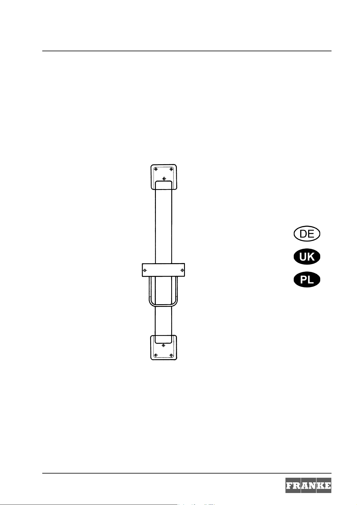
ARTH101
18-05.633b-Exp.fm/13.11.29
...............................................................3
Please refer to the graphics in the German Installation and Operating Instructions.
...............................................................11
Prosimy przyjąć grafikę z niemieckiej instrukcji
montażu i obsługi.
Inhaltsverzeichnis11.fm
2
0English
76 12982 001451 ....... Type 5001 for PROGRESS
Please refer to the graphics in the German Installation and Operating Instructions.
0 Table of Contents
1. Abbreviations and Units. . . . . . . . . . . . . . . . . . . . . . . . . . . . . . . . . . . . 4
2. Key . . . . . . . . . . . . . . . . . . . . . . . . . . . . . . . . . . . . . . . . . . . . . . . . . . . . . 4
3. Warranty . . . . . . . . . . . . . . . . . . . . . . . . . . . . . . . . . . . . . . . . . . . . . . . . 4
4. Important Notes . . . . . . . . . . . . . . . . . . . . . . . . . . . . . . . . . . . . . . . . . . 4
Description of Product
5. Application . . . . . . . . . . . . . . . . . . . . . . . . . . . . . . . . . . . . . . . . . . . . . . 5
6. Technical Specifications. . . . . . . . . . . . . . . . . . . . . . . . . . . . . . . . . . . . 5
7. Scope of Delivery . . . . . . . . . . . . . . . . . . . . . . . . . . . . . . . . . . . . . . . . . 5
8. Dimensions . . . . . . . . . . . . . . . . . . . . . . . . . . . . . . . . . . . . . . . . . . . . . . 5
Installation, Function and Commissioning
9. Installing the Height Adjuster . . . . . . . . . . . . . . . . . . . . . . . . . . . . . . . 5
10. Mounting the Hair Dryers . . . . . . . . . . . . . . . . . . . . . . . . . . . . . . . . . . . 7
11. Function. . . . . . . . . . . . . . . . . . . . . . . . . . . . . . . . . . . . . . . . . . . . . . . . . 7
Maintenance
12. Maintenance and Servicing . . . . . . . . . . . . . . . . . . . . . . . . . . . . . . . . . 7
13. Replacing the Coiled-strip Spring . . . . . . . . . . . . . . . . . . . . . . . . . . . . 8
14. Fault Correction. . . . . . . . . . . . . . . . . . . . . . . . . . . . . . . . . . . . . . . . . . . 9
15. Replacement Parts . . . . . . . . . . . . . . . . . . . . . . . . . . . . . . . . . . . . . . . . 10
18-05.633b-GB.fm
3
1. Abbreviations and Units
RCD Residual Current Protective Device,
EA No. European Article Number
FAR Order No. Franke-AQUAROTTER Order No.
Conversion 1 mm = 0.03937 inches
All length specifications in the graphics are in mm.
2. Key
Leakage current-protective circuit breaker
1inch = 25.4mm
Warning!
Failure to observe can result in injury or even death.
Caution!
Failure to observe can result in material damage.
☞ Important!
Failure to observe can cause the product to malfunction.
☞ Useful information for optimally handling the product.
3. Warranty
Liability is accepted according to the General Terms and Conditions of Business and
Supply.
Use original replacement parts only!
4. Important Notes
• Children and persons with limited capabilities or inadequate knowledge are
permitted to use the equipment only under adult supervision.
• Installation, commissioning and maintenance are to be performed only by a qualified
electrical technician according to the instructions provided and in accordance with
legal requirements and acknowledged rules of technology.
• All technical connection regulations specified by the local electric utility companies
must be complied with.
• All rights reserved to make technical alterations.
4
18-05.633b-GB.fm
5. Application
Height adjuster for hair dryer for application in semi-public as well as public commercial
facilities.
Continuously variable with constant-tension coiled-strip spring, guide rail made of
anodized special aluminium, with 4 mm full-surface glued crystal mirror and concealed
vandal-proof cable routing.
6. Technical Specifications
Operating voltage: 230 V ~ / 50 Hz
Protection class: I
Height adjustment
capability:
600 mm continuous
7. Scope of Delivery
Quantity Description
1Height adjuster
1 Attachment set
1 Installation and Operating Instructions
8. Dimensions
9. Installing the Height Adjuster
Warning!
• The height adjuster for hair dryers must be fastened outside of the range of persons
using a bath or shower.
• Connect the height adjuster to the protective earth conductor system.
• The electrical connection is to be customer-provided with a suitable earth leakage
circuit breaker (RCD) for a maximum nominal fault current of 30 mA.
• The cross section of the electric line must be dimensioned by an electrical specialist
on site.
Failure to observe can mean risk of death or material damage, e.g. from electric shock or
fire.
18-05.633b-GB.fm
5

☞ Important!
• Install the height adjuster vertically on a flat wall surface. Use spacers to compensate
for any uneven wall surfaces (see Accessories, Chapter 15).
• Protect the height adjuster against drill dust.
Failure to observe can cause the height adjuster to work improperly, for example the
guide block may jam.
☞ The recommended distance from the floor to the lower edge of the height adjuster is
1,200 mm.
☞ For on-wall installations, the wall mounts have cable openings in the frontal side.
☞ The recommended distance from the floor to the exit-point of the connecting lines in the
upper wall mount(a) is 2,350mm.
9.1
Mark the holes (b) for the wall mounts (a, e).
9.2
Drill according to the markings. Insert the dowels.
9.3
Use a 3-core-electric cable to provide a permanent electric connection.
9.4
Connect the connecting line to the terminal in the upper wall mount (a).
Option:
Guide the connecting line out from the lower wall mount.
☞ If the existing building situation requires, the electric line can also be guided out from
the wall in the lower wall mount (e).
☞ The recommended distance from the floor to the exit-point of the connecting lines in the
lower wall mount(e) is 1,250mm.
9.5
Install a connecting line from the terminal in the upper wall mount (a) through the
duct (d) to the lower wall mount (e).
9.6
Use a terminal (not included) to connect the connecting line to the electric line in the
lower wall mount (e).
9.7
Use the screws and washers to fasten the height adjuster to the fastening points (b) on
the wall mount.
Caution!
To avoid scratches, use a rubber hammer when driving the covers into the fastening
points.
9.8
Drive the covers into the fastening points so that they are flush with the surface.
18-05.633b-GB.fm
6
 Loading...