

Page 1
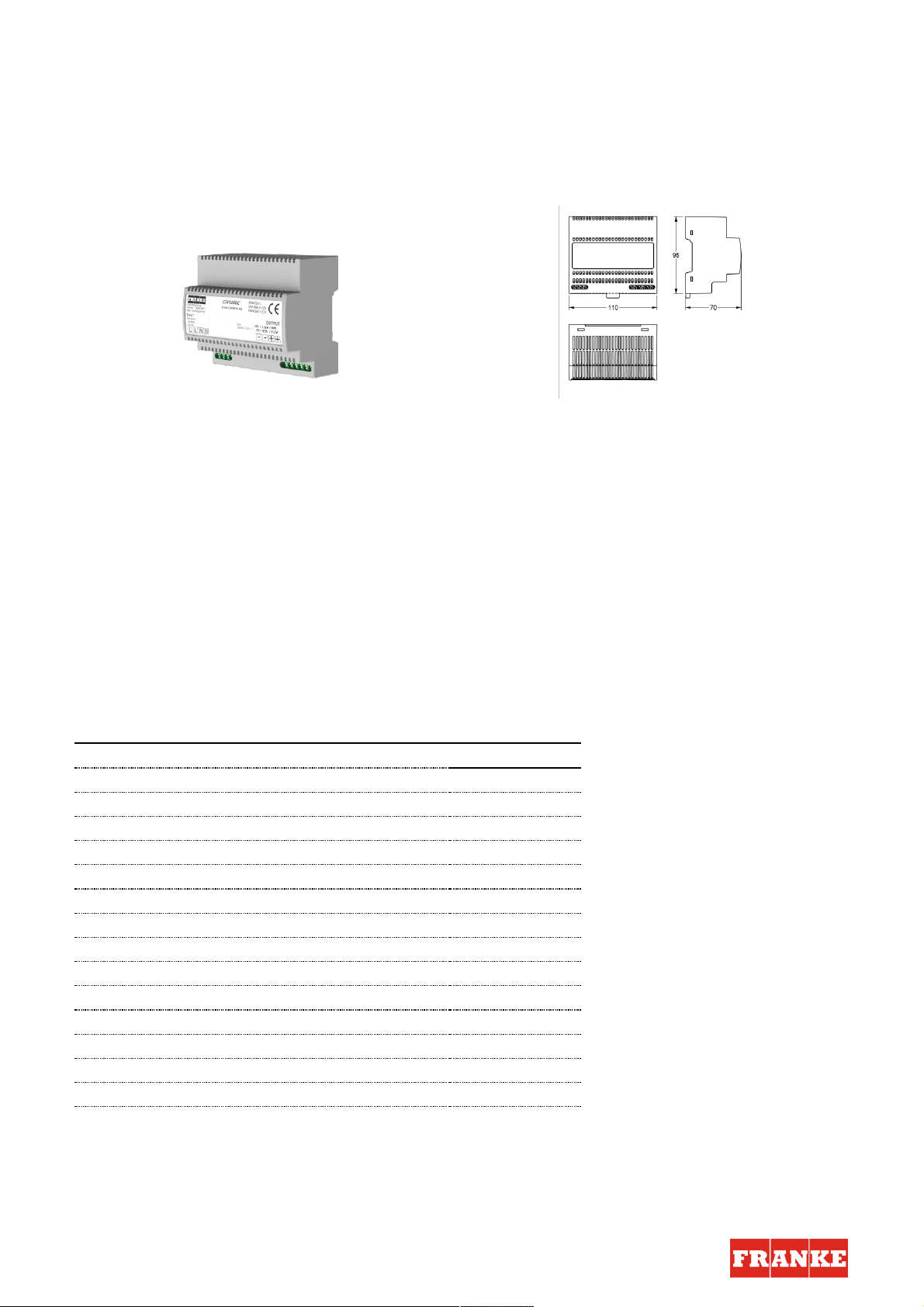
NETZTEIL
ACEX9001 | 2030039477
PRODUKTGRUPPE : Wassermanage ment | ARTIKELFAMILIE : Zubehör
Netzteil für zentrale stabilisierte Gleichstrom-Versorgung. Im Kunststoffgehäuse für Hutschienenmontage. Kurzschlussfeste
Ausführung, mit Sicherheitsabschaltung für angeschlossene bistabile Magnetventile.
Eingangsspannung: 100-240 V AC
Ausgangsspannung: 7 V DC oder 12 V DC (umschaltbar)
Schutzart: IP 20
Leistung: 31,5 W oder 50 W
Wichtiger Hinweis:
Das Netzteil ist zur zentralen Spannungsversorgung von bis zu insgesamt 16 Armaturen der Produktlinien AQUACONTACT
(Betriebsspannung 7 V DC), F3E und F5E (Betriebsspannung jeweils 12 V DC) geeignet. Die Anzahl der Armaturen und die
maximale Kabellänge ist von der Installationsart und dem Kabelquerschnitt abhängig.
TECHNISCHE DATEN
Bruttogewicht 0,51 kg
Nettogewicht 0,49 kg
Kommunikation nein
A3000 kompatibel nein
Eingangsspannung V 230,00 v
Maximale Kabellänge 10 m
Maximaler Ausgangsstrom 50.00 w
Ausgangsspannung 12,00 v
Netzschalter nein
Schutzart IP IP20
Ausgangsspannung (Messeinheit) DC
Gesamttiefe 69,00 mm
Gesamthöhe 95,00 mm
Gesamtbreite 109.00 mm
Franke Water Systems | ws-info.de@franke.com | www.franke.de | 2018-05-17
Page 2
Montage- und Betriebsanleitung
DE
EN
FR
ES
IT
NL
PL
SV
CS
FI
RU
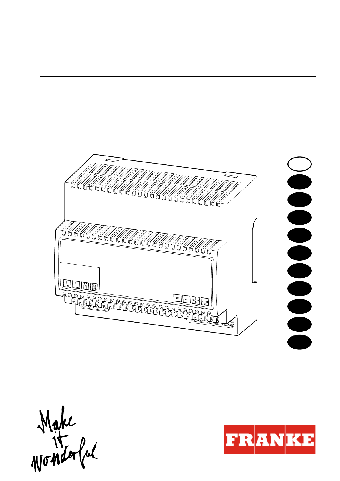
Netzteil
EA-Nr.: 7612982244193
FAR-Best.-Nr.: 2030039477
ACEX9001
ZMI_001_2030039477-ACEX9001_#SDE_#AQU_#V1.fm / 26.07.17
Page 3

Inhaltsverzeichnis
1. Abkürzungen und Einheiten . . . . . . . . . . . . . . . . . . . . . . . . . . . . . 2
2. Zeichenerklärung . . . . . . . . . . . . . . . . . . . . . . . . . . . . . . . . . . . . . 3
3. Gewährleistung. . . . . . . . . . . . . . . . . . . . . . . . . . . . . . . . . . . . . . . 3
4. Wichtige Hinweise . . . . . . . . . . . . . . . . . . . . . . . . . . . . . . . . . . . . 3
Produktbeschreibung
4. Wichtige Hinweise . . . . . . . . . . . . . . . . . . . . . . . . . . . . . . . . . . . . 3
5. Anwendung. . . . . . . . . . . . . . . . . . . . . . . . . . . . . . . . . . . . . . . . . . 3
6. Technische Angaben . . . . . . . . . . . . . . . . . . . . . . . . . . . . . . . . . . 4
7. Maße . . . . . . . . . . . . . . . . . . . . . . . . . . . . . . . . . . . . . . . . . . . . . . 5
8. Lagerung . . . . . . . . . . . . . . . . . . . . . . . . . . . . . . . . . . . . . . . . . . . 5
9. Wichtige Merkmale. . . . . . . . . . . . . . . . . . . . . . . . . . . . . . . . . . . . 5
10. Normen. . . . . . . . . . . . . . . . . . . . . . . . . . . . . . . . . . . . . . . . . . . . . 6
Montage, Funktion und Inbetriebnahme
11. Betriebshinweise . . . . . . . . . . . . . . . . . . . . . . . . . . . . . . . . . . . . . 6
12. Montage/Demontage . . . . . . . . . . . . . . . . . . . . . . . . . . . . . . . . . . 6
13. Anschluss. . . . . . . . . . . . . . . . . . . . . . . . . . . . . . . . . . . . . . . . . . . 7
14. Kurzschluss- und Überlastverhalten. . . . . . . . . . . . . . . . . . . . . . . 8
13. Anschluss. . . . . . . . . . . . . . . . . . . . . . . . . . . . . . . . . . . . . . . . . . . 7
1. Abkürzungen und Einheiten
U
out
L Außenleiter
N Nullleiter
RCD Residual Current Protective Device,
SELV Safety Extra Low Voltage, Schutzkleinspannung
EA-Nr. Europäische Artikelnummer
FAR-Best.-Nr. Franke Aquarotter-Bestellnummer
Ausgangsspannung
Fehlerstromschutzschalter
Umrechnung 1 mm = 0,03937 Zoll
1 Zoll = 25,4 mm
Alle Längenangaben in Grafiken sind in mm angegeben.
- 2 -
ZMI_001_2030039477-ACEX9001_#SDE_#AQU_#V1.fm
Page 4
2. Zeichenerklärung
Warnung!
Nichtbeachtung kann Lebensgefahr oder Körperverletzung bewirken.
Achtung!
Nichtbeachtung kann Sachschäden bewirken.
☞ Wichtig!
Nichtbeachtung kann Funktionsstörungen des Produkts bewirken.
☞ Nützliche Information für den optimalen Umgang mit dem Produkt.
3. Gewährleistung
Haftung wird gemäß den allgemeinen Liefer- und Geschäftsbedingungen
übernommen.
Nur Original-Ersatzteile verwenden!
4. Wichtige Hinweise
• Montage, Inbetriebnahme und Wartung nur durch den Fachmann nach mitgelieferter Anleitung entsprechend den gesetzlichen Vorschrif ten und den anerkannten
Regeln der Technik.
• Die technischen Anschlussbedingungen der örtlichen Wasser- und Energieversorgungsunternehmen einhalten.
• Alle Arbeiten im spannungsfreien Zustand durchführen.
• Änderungen sind vorbehalten.
5. Anwendung
Netzteil nach EMV-Produktnorm und Sicherheit sowie EN60950 (SELV). S tabilisierte
Gleichstrom-Versorgung. Kunststoffgehäuse für Hutschienenmontage. Kurzschlussfeste Ausführung, mit Federklemmen. Mit Sicherheitsabschaltung für
angeschlossene bistabile Magnetventile.
Maximale Kabellänge 10 m bei Kabelquerschnitt 0,32 qmm.
ZMI_001_2030039477-ACEX9001_#SDE_#AQU_#V1.fm
- 3 -
Page 5

6. Technische Angaben
Normen/Zulassungen:
Sicherheit EN 60335-1
EMV EN 55022
Eingang: 100-240 V ac / 50-60 Hz
Spannungsfreien: 85-264 V ac
EN 60950-1
EN 61558-2-16
EN 55024
EN 61000-3-2
EN 61000-3-3
EN 61000-6-2
EN 61000-6-3
EN 61204-3
RoHS
Frequenz: 44 bis 66 Hz
Eingangsstrom: typ 1,05 A bei 230 V ac
Ausgang:
Anschlussspannung: 6,75-7,5 V / 12-14 V
Ausgangsseitig: 4 A
Argillite: < 150 mVpp (bei 20 MHz Bandbreite)
Schutzart: IP 20
Umgebungstemperatur: -25°C bis +55°C
Lagertemperatur: -40°C bis +85°C
Signalisierung LED: LED grün
Besonderheiten: Kurzschluss- und leerlauffest
- 4 -
ZMI_001_2030039477-ACEX9001_#SDE_#AQU_#V1.fm
Page 6
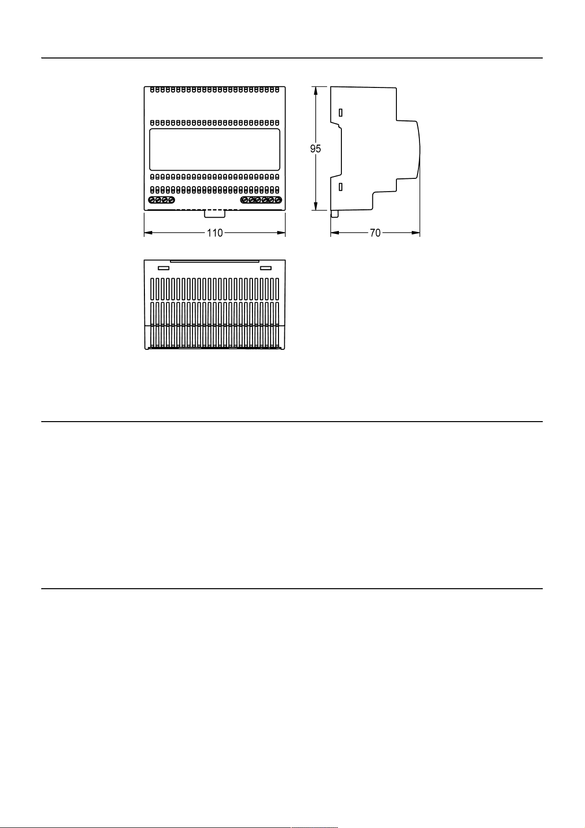
7. Maße
8. Lagerung
zulässige Lagerungstemperatur: -40 °C ... + 85 °C
zulässige Luftfeuchtigkeit: 30 ... 95 % relative Feuchte; bei Inbetrieb-
nahme darf keine Betauung vorliegen.
bei Langzeitlagerung: Betriebsmittel mit eingebauten Kondensatoren
sind mindestens alle 2 Jahre für mindestens
5 min an Netzspannung anzulegen
9. Wichtige Merkmale
• Weitbereichs AC-Eingang ohne Umschaltung
• Schutzklasse 2
• primärseitig durch interne Sicherung geschützt
• Umschaltung zwischen 7 V und 12 V möglich.
• Montage für Hutschiene nach EN 50022
ZMI_001_2030039477-ACEX9001_#SDE_#AQU_#V1.fm
- 5 -
Page 7
10. Normen
a
b
Die elektrische Sicherheit ist durch einen Geräteaufbau nach EN 60950 (VDE 0805)
gegeben. Es entspricht den Anforderungen und Normen zur CE-Konformität und
trägt das CE-Zeichen.
11. Betriebshinweise
Die Kühlung des Betriebsmittels darf nicht beeinträchtigt werden. Eine ungehinderte
Luftzufuhr und ein Mindestabstand von 15 mm zu benachbarten Teilen sind sicherzustellen.
Die Verdrahtung der Anschlussklemmen darf nur im spannungslosen Zustand
erfolgen. Aufgrund der Schutzart IP 20 ist der Betrieb des Gerätes nur in trockenen
Räumen zulässig.
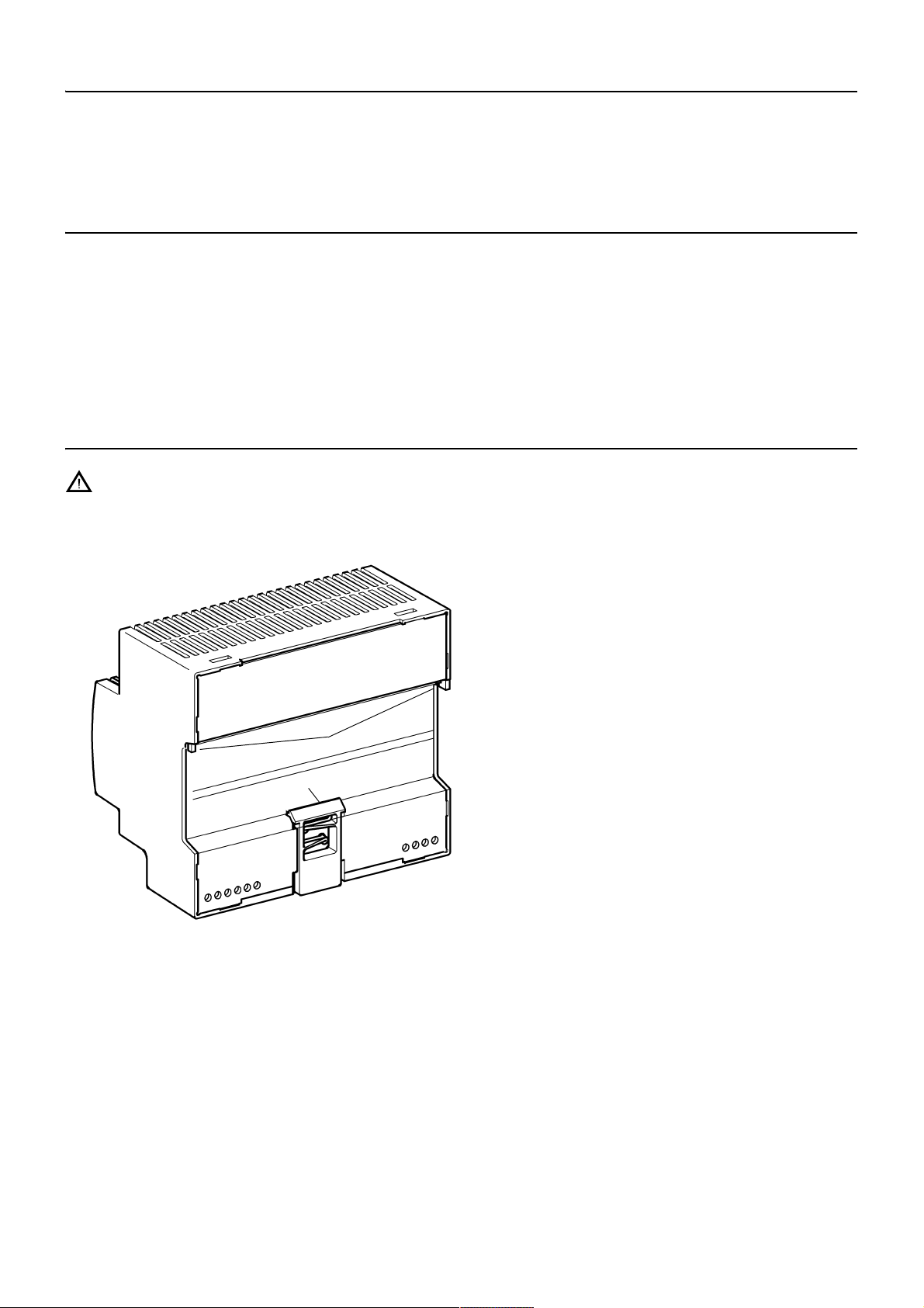
12. Montage/Demontage
Achtung!
Das Systemnetzteil darf nur als SELV-Stromkreis betrieben werden. Das heißt, die
Systemleitung darf an keinem Punkt geerdet werden.
Montage auf Hutschienen
12.1
Das Netzteil oben (a) auf eine
Hutschiene 35 mm nach EN 50022
einhaken.
12.2
Das Netzteil unten gegen die
Hutschiene drücken, bis die Lasche
(b) einrastet.
☞ Beim Anreihen von Modulen ist ein
Mindestabstand von 15 mm einzuhalten.
Demontage von Hutschienen
12.3
Die Lasche (b) nach unten ziehen
und das Netzteil unten aushängen.
12.4
Das Netzteil nach oben abziehen
ZMI_001_2030039477-ACEX9001_#SDE_#AQU_#V1.fm
- 6 -
Page 8
13. Anschluss
a
b
benötigte Materialien
Bauseits stellen:
• Feuchtraum-Verteilerdose (Ø 68 mm)
• Fehlerstromschutzschalter (RCD)
• Leerrohr für Anschlusskabel (Ø 10 mm)
• Leerrohr für Kabel
• 2-adriges Kabel
☞ Die Stromversorgung außerhalb des Nassbereichs in einem extra Raum platzieren
und mit einem Fehlerstromschutzschalter (RCD) absichern.
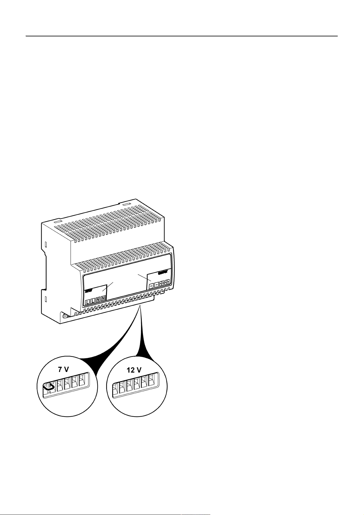
13.1
Vorm Anschluss des Netzteiles die
zugehörige Betriebsspannung (siehe
Typenschild) prüfen.
13.2
Die Stromversorgung an die
Klemmen Input L und N (a)
anschließen.
13.3
Die Armaturen an die Klemmen
Output + und - (b) anschließen.
+ … rot
– … schwarz
Folgende Anschlusskabel verwenden:
Primärseitig (230 VAC):
Ausschließlich geeignete Installationskabel nach VDE (z. B. NYM 3×1,5 mm²)
verwenden.
Sekundärseitig (7 VDC/ 12 VDC):
Ausschließlich Original-Anschlusskabel
(FAR-Best.-Nr. 2030010982) verwenden.
Nur für 7 V:
Der Widerstand über die Gesamtlänge
des Kabels (vom Netzteil zur Armatur)
muss kleiner als 3,4 Ohm sein.
Der Querschnitt ist entsprechend der
Kabellänge zu wählen.
ZMI_001_2030039477-ACEX9001_#SDE_#AQU_#V1.fm
- 7 -
Page 9
13.4
c
d
e
f
f
g
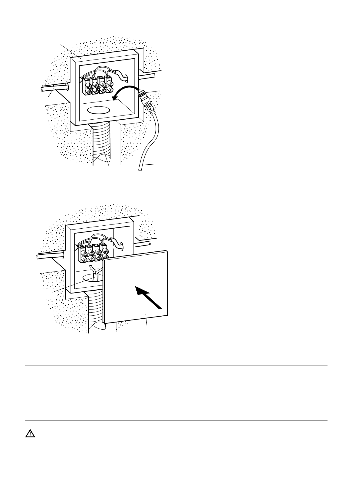
Je Armatur eine Feuchtraum-Verteilerdose (c) installieren.
13.5
Ein Leerrohr (e; Ø 16 mm) von der
Feuchtraum-Verteilerdose zum
Wandeinbaukasten verlegen.
13.6
Ein flexibles 2-adriges Kabel (d) im
Leerrohr verlegen und von
Feuchtraum-Verteilerdose zu
Feuchtraum-Verteilerdose schieben.
13.7
Das Anschlusskabel (f) für den
Sensor durch das Leerrohr (e)
schieben.
☞ Der Stecker muss im Wandeinbau-
kasten gut zugänglich sein.
13.8
Das Anschlusskabel (f) für den
Sensor in der Feuchtraum-Verteilerdose anschließen.
14. Kurzschluss- und Überlastverhalten
Bei Kurzschluss im Netzbetrieb bleibt der Ausgang freigeschaltet. Die genannten
Spannungsschwellen für das Zu- und Abschalten gelten nach einem Kurzschluss
erst nach Spannungsfreischaltung auf der Primärseite oder Wiedererreichen der
Spannungsschwelle von 7 V.
15. Sicherungen
13.9
Die Feuchtraum-V erteilerdose mit der
Schutzkappe (g) verschließen.
Achtung!
Das Netzteil ist intern primärseitig mit einer Sicherung 1,6 AT/250 V abgesichert.
Wenn diese Sicherung auslöst, liegt mit hoher Wahrscheinlichkeit ein Gerätedefekt
vor.
- 8 -
ZMI_001_2030039477-ACEX9001_#SDE_#AQU_#V1.fm
Page 10
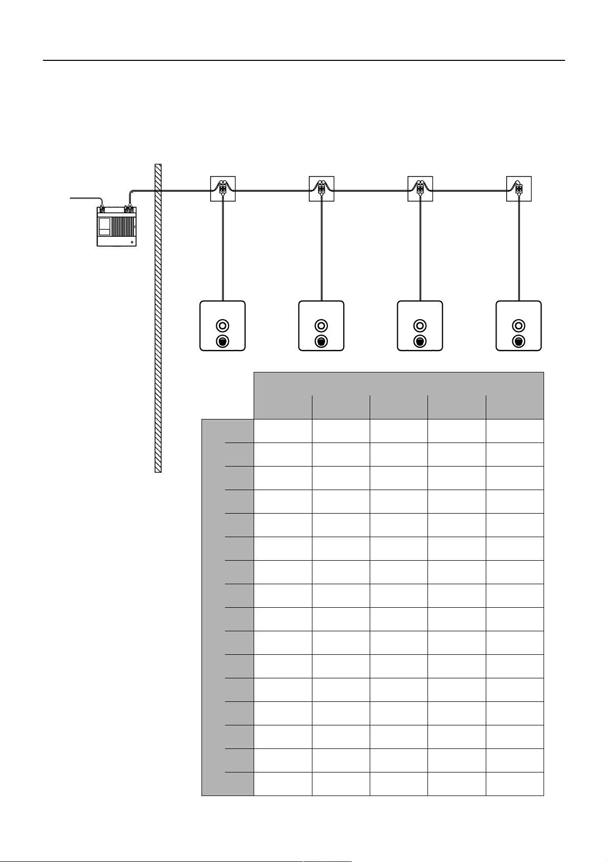
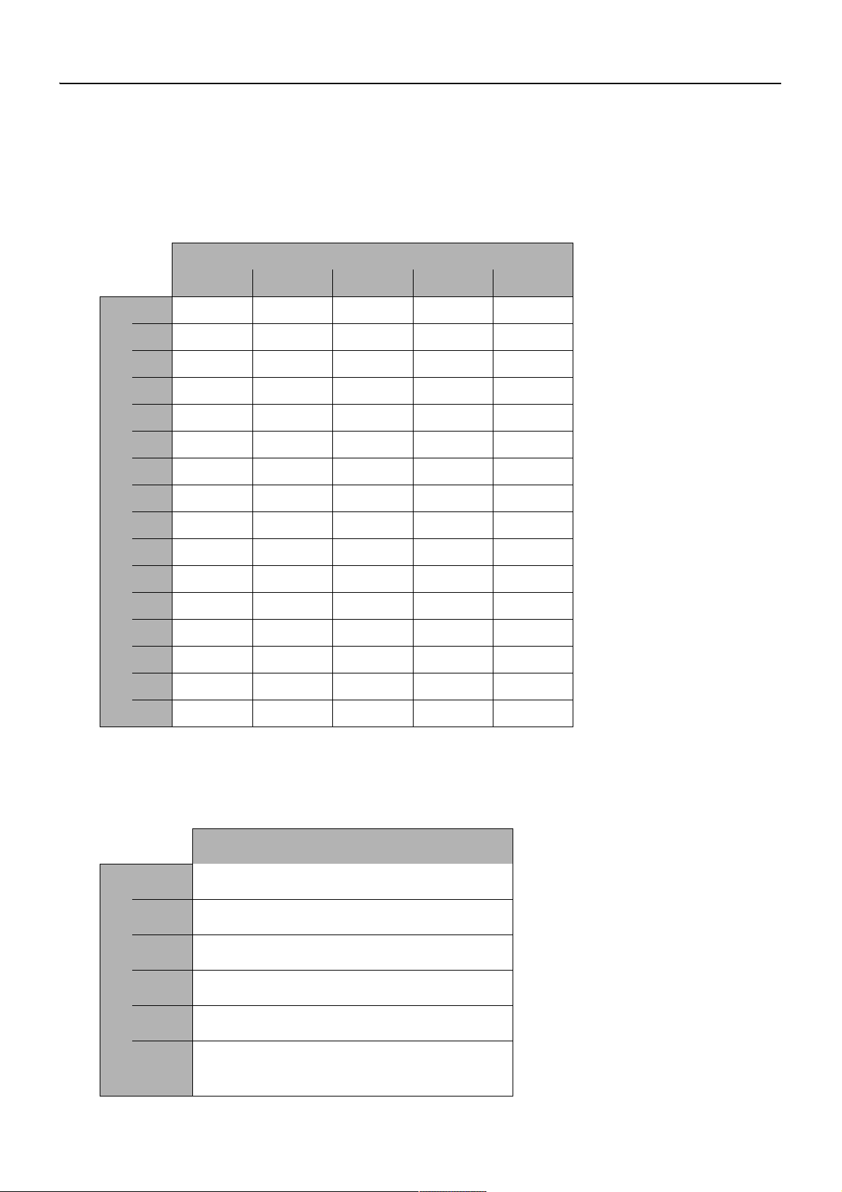
16. Anschlussbeispiel (nur für 7 V)
A: max. Kabellänge siehe Tabelle
B: Netzteil
230 V AC
Q: Querschnitt in mm
2
0,5 0,75 1 1,5 2,5
N: Anzahl der Armaturen
1 40 m 60 m 80 m 120 m 200 m
2 20 m 30 m 40 m 60 m 100 m
3 14 m 20 m 25 m 40 m 70 m
4 10 m 15 m 20 m 30 m 50 m
5 8 m 12 m 15 m 25 m 40 m
6 7 m 10 m 14 m 22 m 35 m
7 5 m 8 m 12 m 19 m 31 m
8 5 m 8 m 11 m 16 m 27 m
9 5 m 7 m 10 m 12 m 20 m
10 4 m 6 m 8 m 12 m 20 m
11 4 m 6 m 8 m 12 m 20 m
12 4 m 5 m 7 m 11 m 18 m
13 3 m 5 m 7 m 10 m 17 m
14 3 m5 m6 m9 m16 m
15 3 m4 m6 m9 m15 m
16 2 m4 m5 m8 m14 m
☞ Die maximale Kabellänge und Armaturenanzahl hängt von der Installationsart und
des Kabelquerschnitts ab.
16.1 Installationsbeispiel Linien-Struktur
ZMI_001_2030039477-ACEX9001_#SDE_#AQU_#V1.fm
- 9 -
Page 11
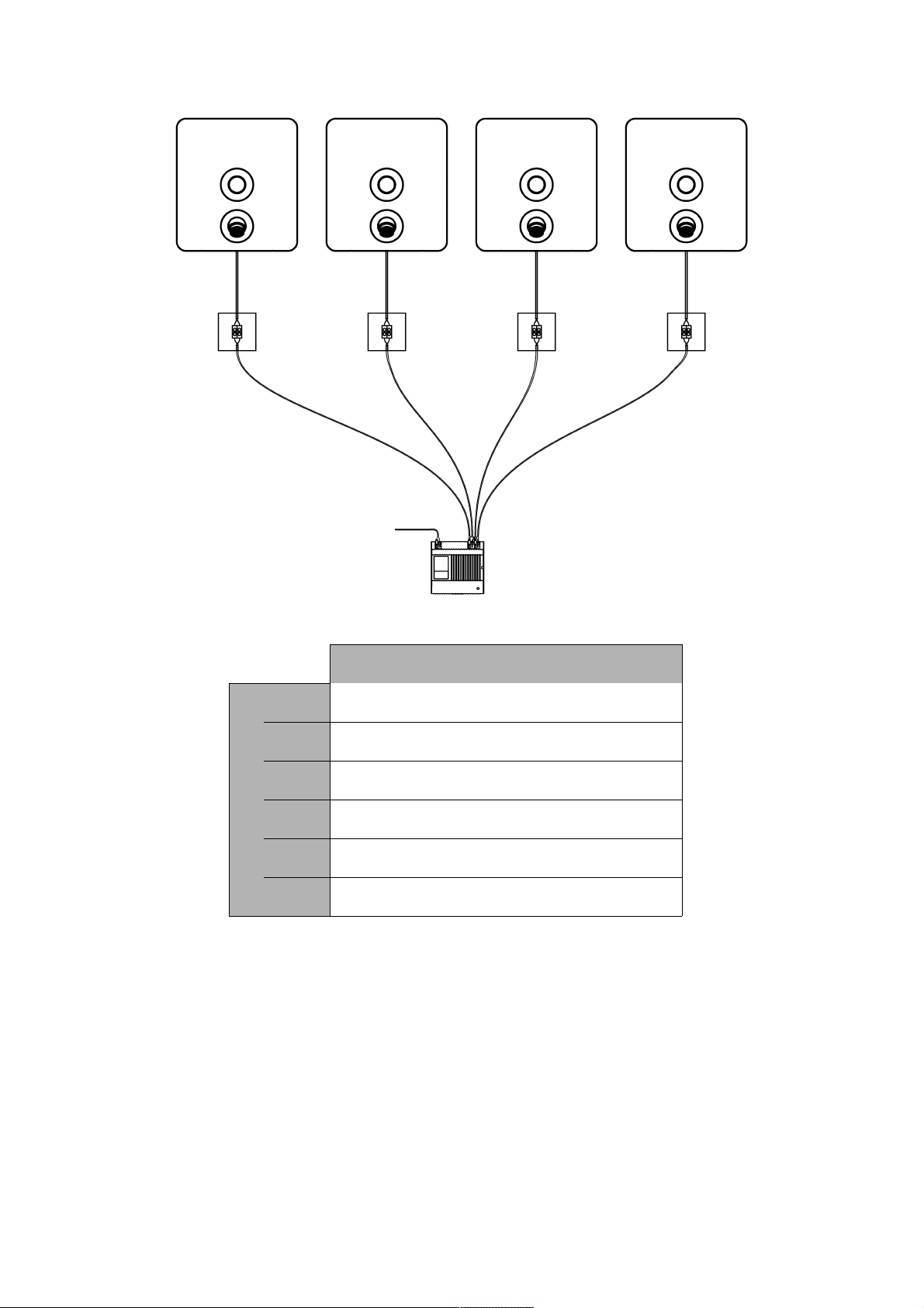
16.2 Installationsbeispiel Sternform
B: Netzteil
max. 12 Armaturen
230 V AC
A: max. Kabellänge
siehe Tabelle
L: maximale Kabellänge in m
Q: Querschnitt in mm
2
0,25 20
0,5 40
0,75 60
1 80
1,5 120
2,5 200
ZMI_001_2030039477-ACEX9001_#SDE_#AQU_#V1.fm
- 10 -
Page 12

Notizen
ZMI_001_2030039477-ACEX9001_#SDE_#AQU_#V1.fm
- 11 -
Page 13

Australia
PR Kitchen and Water Systems Pty Ltd
Dandenong South VIC 3175
Phone +61 3 9700 9100
Austria
Franke GmbH
6971 Hard
Phone +43 5574 6735 0
Belgium & Luxembourg
Franke N.V.
9400 Ninove, Belgium
Phone +32 54 310 130
Czech Republic
Franke Aquarotter GmbH
14974 Ludwigsfelde, Germany
Phone +420 281 090 429
France
Franke GmbH
6971 Hard, Austria
Phone +33 800 909 216
Germany
Franke Aquarotter GmbH
14974 Ludwigsfelde
Phone +49 3378 818 530
Italy
Franke Water Systems AG
4663 Aarburg, Switzerland
Numero Verde 800 789 233
Middle East
Franke LLC
Ras Al Khaimah, United Arab Emirates
Phone +971 7 2034 700
Morocco
Franke Kitchen System SARL
21 000 Casablanca
Phone +212 522 674 200
Netherlands
Franke N.V.
9400 Ninove, Belgium
Phone +31 492 72 82 24
Poland
Franke Aquarotter GmbH
14974 Ludwigsfelde, Germany
Phone +48 22 711 6717
Portugal
Franke Portugal S.A.
2735-531 Cacém
Phone +351 21 426 9670
South Africa & Sub Saharan Africa
Franke South Africa
Durban, 4052
Phone + 27 31 450 6300
Spain
Franke GmbH
6971 Hard, Austria
Phone +43 5574 6735 211
Switzerland & Liechtenstein
Franke Water Systems AG
4663 Aarburg
Phone +41 62 787 3131
Tur key
Franke Mutfak ve Banyo Sistemleri
Sanayi ve Ticaret A.S.
41400 Gebze Kocaeli
Phone +90 262 644 6595
United Kingdom
Franke Sissons Ltd.
Barlborough S43 4PZ
Phone +44 1246 450 255
Dart Valley Systems Ltd.
Paignton TQ4 7TW
Phone +44 1803 529 021
EAST EUROPE
Bosnia Herzegovina | Bulgaria |
Croatia | Hungary | Latvia | Lithuania |
Romania | Russia | Serbia | Slovakia |
Slovenia | Ukraine
Franke Aquarotter GmbH
14974 Ludwigsfelde, Germany
Phone +49 3378 818 530
NORTH AMERICA
United States | Canada
Franke Kindred Canada Limited
Midland, ON L4R 4K9, Canada
Phone +1 855 446 5663
SCANDINAVIA & ESTONIA
Finland | Sweden | Norway |
Denmark | Estonia
Franke Finland Oy
76850 Naarajärvi, Finland
Phone +358 15 34 111
OTHER COUNTRIES
Franke GmbH
6971 Hard, Austria
Phone +43 5574 6735 0
www.franke.com
© Franke Technology and Trademark Ltd., Switzerland / 26.07.17 / 2030039569
Page 14
Installation and operating instructions Montaż i instrukcja obsługi
DE
EN
FR
ES
IT
NL
PL
SV
CS
FI
RU
Notice de montage et de mise en service Monterings- og driftsvejledning
Instrucciones de montaje y uso Návod pro montáž a provoz
Istruzioni per il montaggio e l’uso Asennus- ja käyttöohje
Montage- en bedrijfsinstructies Инструкция по монтажу и вводу в
эксплуатацию
EA-Nr.: 7612982244193
FAR-Best.-Nr.: 2030039477
ACEX9001
ZMI_001_2030039477-ACEX9001_#SALL_#AQU_#V1.fm / 26.07.17
Page 15
...................................................................................3
Please refer to the graphics in the German Installation and
Operating Instructions.
...................................................................................10
Les graphiques sont disponibles dans la notice de montage et
de mise en service allemande.
...................................................................................17
Por favor, consulte los gráficos en las instrucciones alemanas
de montaje y uso.
...................................................................................24
Per le grafiche fare riferimento alle Istruzioni per il montaggio
e l’uso in tedesco.
...................................................................................31
De tekeningen kunt u in de Duitse montage- en bedrijfsinstructies vinden.
...................................................................................38
Prosimy przyjąć grafikę z niemieckiej instrukcji montażu i
obsługi.
...................................................................................45
Bilderna finns i den tyska monterings- och bruksanvisningen.
...................................................................................52
Obrázky najdete v nìmeckém návodu k montáži a obsluze.
...................................................................................59
Kuvat löydätte saksankielisestä asennus- ja käyttöohjeesta.
...................................................................................66
Рисунки приведены в инструкции по монтажу и
эксплуатации на немецком языке.
EN
FR
ES
IT
NL
PL
SV
CS
FI
RU
Inhaltsverzeichnis35.fm
2
Page 16

0English
EN
Power Supply
Please refer to the graphics in the German Installation and Operating Instructions.
0 Table of Contents
1. Abbreviations and Units . . . . . . . . . . . . . . . . . . . . . . . . . . . . . . . . 4
2. Key . . . . . . . . . . . . . . . . . . . . . . . . . . . . . . . . . . . . . . . . . . . . . . . . 4
3. Warranty . . . . . . . . . . . . . . . . . . . . . . . . . . . . . . . . . . . . . . . . . . . . 4
4. Important Notes . . . . . . . . . . . . . . . . . . . . . . . . . . . . . . . . . . . . . . 4
Description of Product
5. 5. Application . . . . . . . . . . . . . . . . . . . . . . . . . . . . . . . . . . . . . . . . 5
6. Technical Specifications . . . . . . . . . . . . . . . . . . . . . . . . . . . . . . . . 5
7. Dimensions. . . . . . . . . . . . . . . . . . . . . . . . . . . . . . . . . . . . . . . . . . 5
8. Storage. . . . . . . . . . . . . . . . . . . . . . . . . . . . . . . . . . . . . . . . . . . . . 6
9. Most Important Features . . . . . . . . . . . . . . . . . . . . . . . . . . . . . . . 6
10. Standards . . . . . . . . . . . . . . . . . . . . . . . . . . . . . . . . . . . . . . . . . . . 6
Installation, Function and Commissioning
11. Notes on Operation . . . . . . . . . . . . . . . . . . . . . . . . . . . . . . . . . . . 6
12. Installing/Removing . . . . . . . . . . . . . . . . . . . . . . . . . . . . . . . . . . . 7
13. Connection . . . . . . . . . . . . . . . . . . . . . . . . . . . . . . . . . . . . . . . . . . 7
14. Short Circuit and Overload Behaviour . . . . . . . . . . . . . . . . . . . . . 8
15. Fuses . . . . . . . . . . . . . . . . . . . . . . . . . . . . . . . . . . . . . . . . . . . . . . 8
16. Connection Example (only for 7 V). . . . . . . . . . . . . . . . . . . . . . . . 9
EN
ZMI_001_2030039477-ACEX9001_#SEN_#AQU_#V1.fm
- 3 -
Page 17
1. Abbreviations and Units
U
out
L Phase conductor
N Earth wire
RCD Residual Current Protective Device,
SELV Safety Extra Low Voltage
EA-Nr. European Article Number
FAR-Best.-Nr. Franke Aquarotter Order Number
Conversion 1 mm = 0.03937 inches
All length specifications in the graphics are in mm.
2. Key
Output voltage
Earth leakage circuit breaker
1 inches = 25,4 mm
Warning!
Failure to observe can result in injury or even death.
Caution!
Failure to observe can cause the product to malfunction.
☞ Important!
Failure to observe can cause the product to malfunction.
☞ Useful information for optimally handling the product.
3. Warranty
Liability is accepted according to the General Terms and Conditions of Business and
Supply.
Use original replacement parts only!
4. Important Notes
• Installation, commissioning and maintenance are to be performed only by a
qualified technician according to the instructions provided and in accordance with
legal requirements and acknowledged rules of technology.
• All technical connection regulations specified by the local water and electricity
supply utility companies must be complied with.
• All work must be carried out in a de-energised state.
• All rights reserved to make technical alterations.
- 4 -
ZMI_001_2030039477-ACEX9001_#SEN_#AQU_#V1.fm
Page 18

5. 5. Application
Power supply in compliance with EMC product standard and Safety. Stabilized DC
power supply. Plastic housing for DIN rail mounting. Short-circuit-proof design, with
spring terminals. With safety shut-down for connected bistable solenoid valves.
Maximum cable length 10 m with cable cross section 0.32 mm²
6. Technical Specifications
Standards / Approvals
Safety EN 60335-1
EN 60950-1
EN 61558-2-16
EMC EN 55022
EN 55024
EN 61000-3-2
EN 61000-3-3
EN 61000-6-2
EN 61000-6-3
EN 61204-3
RoHS
Input: 100-240 V ac / 50-60 Hz
Voltage range: 85-264 V ac
Frequency: 44 to 66 Hz
Input current: typ 1.05 A at 230 V AC
Output:
Output voltage: 6,75-7.5 V / 12-14 V
Output current: 4 A
Ripple: < 150 mVpp (at 20 MHz bandwidth)
Type of protection: IP 20
Ambient temperature: -25°C to +55°C
Storage temperature: -40°C to +85°C
LED signalling: Green LED
Special features: Short-circuit proof and open-circuit proof
7. Dimensions
ZMI_001_2030039477-ACEX9001_#SEN_#AQU_#V1.fm
- 5 -
Page 19

8. Storage
permissible storage temperature: -40 °C ... + 85 °C
Permissible humidity:
bei Langzeitlagerung:
30 ... 95 % relative humidity; there must be
no condensation present when the system is
started up.
With long-term storage: Appliances with
built-in capacitors must be connected to
mains voltage for at least 5 minutes every
2years.
9. Most Important Features
• Wide-range AC input without switching
• Protection class 2
• Primary side protected by internal circuit breaker
• 7 V and 12 V output voltage can be selected.
• Mounting for DIN rail according to EN 50022
10. Standards
Electrical safety is provided by means of a design in compliance with EN 60950
(VDE 0805). It meets the requirements and standards required for CE conformity
and carries the CE symbol.
11. Notes on Operation
Appliance cooling must not be impaired. In order to ensure an unimpeded flow of air,
a minimum distance of 15 mm to adjacent parts must be maintained.
Wiring connections to the connector terminals must only be made in an electrically
dead condition. Due to the type of protection used (IP 20), the device must be
operated in dry rooms only.
- 6 -
ZMI_001_2030039477-ACEX9001_#SEN_#AQU_#V1.fm
Page 20

12. Installing/Removing
Caution!
The system power supply must be operated only as a SELV circuit. This means that
the system line must not be earthed at any point.
Installation on DIN Mounting Rails
12.1
Hook the power supply into a (a) 35 mm DIN rail (top side) in compliance with
EN 50022.
12.2
Press the power supply (bottom side) into the DIN rail until the tab (b) snaps into
place.
☞ When lining up several modules on the rail, maintain a minimum spacing of 15 mm.
Removal from DIN Mounting Rails
12.3
Pull the tab (b) downwards and unhook the power supply (bottom side).
12.4
Pull off the power supply upwards.
13. Connection
Materials Required
To be provided by the customer:
• Moisture-proof junction box (Ø 68 mm)
• Earth leakage circuit breaker (RCD)
• Empty conduit for connecting cables (Ø 10 mm)
• Empty conduit for cables
• 2-wire cable
☞ Position the power supply outside of the wet area, in a separate room, and protect it
with an earth leakage circuit breaker (RCD).
13.1
Before connecting the power supply, check that the correct voltage is available (see
type plate).
13.2
Connect the power supply to input terminals L and N (a).
13.3
Connect the fittings to output terminals + and - (b).
+ … red
– … black
ZMI_001_2030039477-ACEX9001_#SEN_#AQU_#V1.fm
- 7 -
Page 21

Use the following connecting cables:
Primary side (230 VAC)
Use only suitable installation cables in compliance with VDE (e.g. NYM 3×1.5 mm²).
Secondary side (7 VDC/ 12 VDC)
Use only original connection cable (FAR Order No. 2030010982).
Only for 7 V:
The resistance over the entire length of the cable (from the power supply to the
fitting) must be less than 3.4 ohms.
The cross-section must be selected according to the cable length.
13.4
Install one moisture-proof junction box per fitting (a).
13.5
Run an empty conduit (c; Ø 10 mm) from the moisture-proof junction box to the
flush-mounting cabinet.
13.6
Lay a 2-wire cable (b) in the empty conduit and slide it from the moisture-proof
junction box to the moisture-proof junction box.
13.7
Slide the connecting cable (d) for the sensor through the empty conduit (c).
☞ The plug must be easily accessible for the fitting.
13.8
Connect the connecting cable (d) in the moisture-proof junction box.
13.9
Close the moisture-proof junction box with the protective cap (e).
13.10
Connect the extension cable to the fitting.
14. Short Circuit and Overload Behaviour
In the event of a short circuit during network operation, the output remains
disconnected. After a short circuit, the voltage thresholds specified for activation and
deactivation apply only after power has been deactivated on the primary side or after
the voltage threshold of 7 V has been reached.
15. Fuses
Caution!
The power supply is secured with a 1.6 AT/250 V fuse on the primary side. When
this fuse triggers, it is very probable that the device is defective.
- 8 -
ZMI_001_2030039477-ACEX9001_#SEN_#AQU_#V1.fm
Page 22
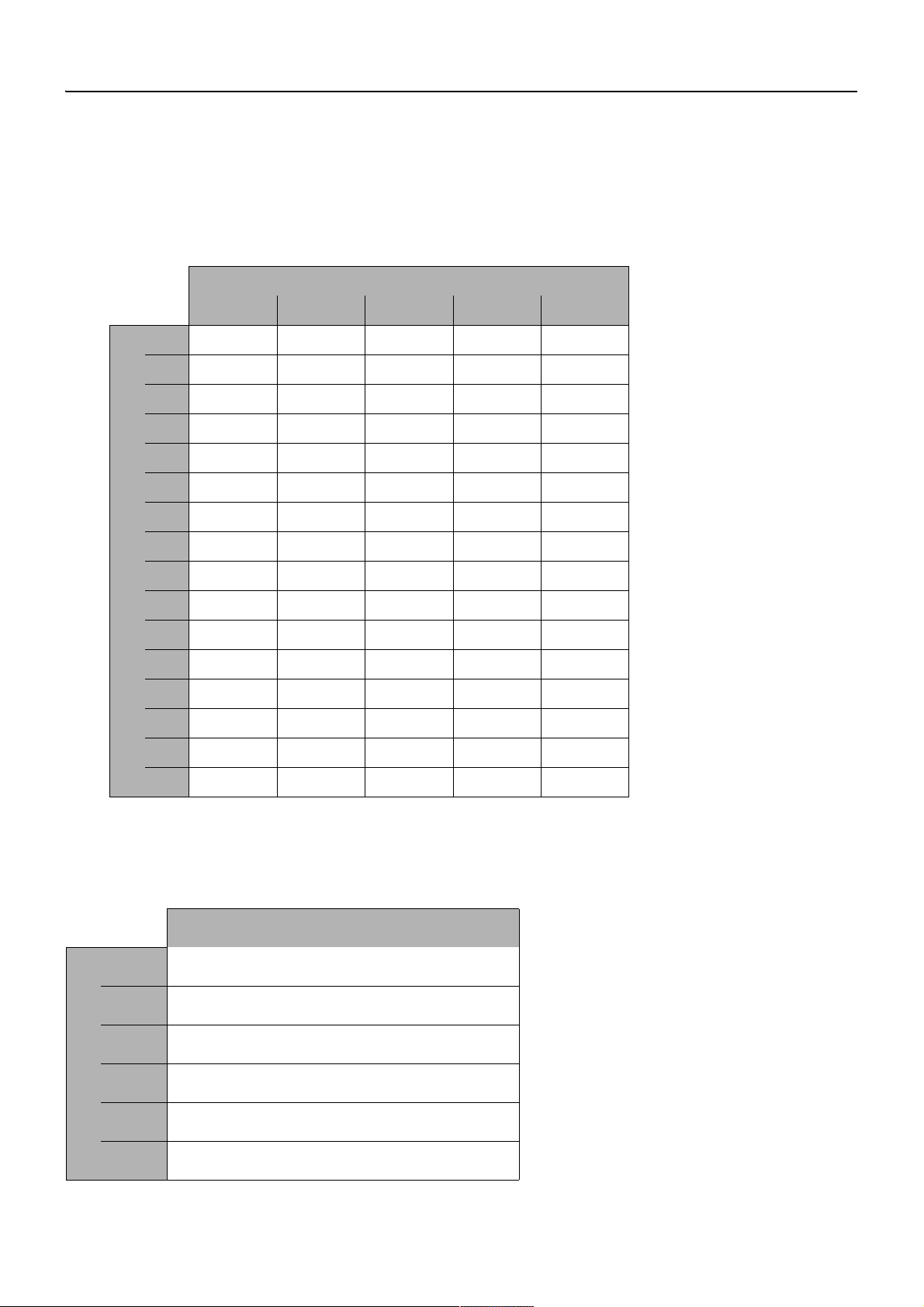
16. Connection Example (only for 7 V)
☞ The maximum cable length and number of fittings depends on the type of installation
and the cross section of the cable.
16.1 Installation example, in-line structure
A: Max. cable length see table
B: Power supply
Q: Cross-section in mm
2
0,5 0,75 1 1,5 2,5
1 40 m 60 m 80 m 120 m 200 m
2 20 m 30 m 40 m 60 m 100 m
3 14 m 20 m 25 m 40 m 70 m
4 10 m 15 m 20 m 30 m 50 m
5 8 m 12 m 15 m 25 m 40 m
6 7 m 10 m 14 m 22 m 35 m
7 5 m 8 m 12 m 19 m 31 m
8 5 m 8 m 11 m 16 m 27 m
9 5 m 7 m 10 m 12 m 20 m
10 4 m 6 m 8 m 12 m 20 m
11 4 m 6 m 8 m 12 m 20 m
N: Number of fittings
12 4 m 5 m 7 m 11 m 18 m
13 3 m 5 m 7 m 10 m 17 m
14 3 m5 m6 m9 m16 m
15 3 m4 m6 m9 m15 m
16 2 m4 m5 m8 m14 m
16.2 Installation example, star structure
A: Max. cable length, see table
B: Power supply, max. 12 fittings
L: Maximum cable length in m
2
0,25 20
0,5 40
0,75 60
1 80
1,5 120
2,5 200
Q: Cross-section in mm
ZMI_001_2030039477-ACEX9001_#SEN_#AQU_#V1.fm
- 9 -
Page 23

0Français
FR
Bloc secteur
Les graphiques sont disponibles dans la notice de montage et de mise en service
allemande.
0 Table des matières
1. Abréviations et unités . . . . . . . . . . . . . . . . . . . . . . . . . . . . . . . . . . 11
2. Explication des symboles . . . . . . . . . . . . . . . . . . . . . . . . . . . . . . . 11
3. Garantie . . . . . . . . . . . . . . . . . . . . . . . . . . . . . . . . . . . . . . . . . . . . 11
4. Remarques importantes . . . . . . . . . . . . . . . . . . . . . . . . . . . . . . . . 12
Description du produit
5. Application . . . . . . . . . . . . . . . . . . . . . . . . . . . . . . . . . . . . . . . . . . 12
6. Données techniques. . . . . . . . . . . . . . . . . . . . . . . . . . . . . . . . . . . 12
7. Dimensions. . . . . . . . . . . . . . . . . . . . . . . . . . . . . . . . . . . . . . . . . . 13
8. Stockage. . . . . . . . . . . . . . . . . . . . . . . . . . . . . . . . . . . . . . . . . . . . 13
9. Caractéristiques principales . . . . . . . . . . . . . . . . . . . . . . . . . . . . . 13
10. Normes . . . . . . . . . . . . . . . . . . . . . . . . . . . . . . . . . . . . . . . . . . . . . 13
Montage, fonctionnement et mise en service
11. Remarques relatives au fonctionnement . . . . . . . . . . . . . . . . . . . 13
12. Montage/Démontage . . . . . . . . . . . . . . . . . . . . . . . . . . . . . . . . . . 14
13. Raccordement . . . . . . . . . . . . . . . . . . . . . . . . . . . . . . . . . . . . . . . 14
14. Comportement au court-circuit et à la surcharge . . . . . . . . . . . . . 15
15. Fusibles . . . . . . . . . . . . . . . . . . . . . . . . . . . . . . . . . . . . . . . . . . . . 15
16. Exemple de raccordement (uniquement pour 7 V). . . . . . . . . . . . 16
ZMI_001_2030039477-ACEX9001_#SFR_#AQU_#V1.fm
- 10 -
Page 24

1. Abréviations et unités
U
out
L Conducteur extérieur
N Conducteur neutre
RCD Residual Current Protective Device,
SELV Safety Extra Low Voltage, basse tension de
EA-Nr. Numéro d’article européen
FAR-Best.-Nr. Numéro de commande Franke Aquarotter
Umrechnung 1 mm = 0,03937 pouce
Tension de sortie
interrupteur de protection contre les courants de
court-circuit
protection
1 pouce = 25,4 mm
Dans les graphiques, toutes les longueurs sont indiquées en mm.
2. Explication des symboles
Avertissement !
Le non-respect des consignes est susceptible d'induire un danger de mort ou de
provoquer des blessures corporelles.
Attention !
Le non-respect des consignes est susceptible de provoquer des dommages
matériels.
☞ Important !
Le non-respect des consignes est susceptible de provoquer des dysfonctionnements du produit..
☞ Informations utiles pour une utilisation optimale du produit.
3. Garantie
La responsabilité est assumée conformément aux conditions générales de vente et
de livraison.
Utiliser uniquement des pièces de rechange d’origine !
ZMI_001_2030039477-ACEX9001_#SFR_#AQU_#V1.fm
- 11 -
Page 25

4. Remarques importantes
• Seul un spécialiste est habilité à effectuer le montage, la mise en service et
l’entretien de l’installation, ces opérations étant effectuées selon les instructions
fournies, conformément aux prescriptions légales et aux règles techniques
reconnues.
• Il convient de respecter les conditions techniques de raccordement des entreprises locales de distribution d’eau et d’énergie.
• Effectuez tous les travaux quand le dispositif est hors tension.
• Sous réserve de modifications.
5. Application
Fiche secteur selon norme de produit et de sécurité. Alimentation en courant
continu stabilisé. Moulage avec boîtier en plastique pour montage sur rail en U.
Exécution avec protection contre le court-circuit avec des pinces à ressort.
Avec arrêt de sécurité pour électrovannes bistables raccordées. Longueur de câble
maximale 10 m pour un diamètre de 0,32 mm².
6. Données techniques
Normes/Autorisations:
Sécurité EN 60335-1
EN 60950-1
EN 61558-2-16
CEM EN 55022
EN 55024
EN 61000-3-2
EN 61000-3-3
EN 61000-6-2
EN 61000-6-3
EN 61204-3
RoHS
Entrée: 100-240 V ac / 50-60 Hz
Plage de tension: 85-264 V ac
Fréquence: 44 à 66 Hz
Courant d'entrée: typ 1,05 A à 230 V ac
Sortie:
Tension de sortie: 6,75-7,5 V / 12-14 V
Courant de sortie: 4 A
Ondulation: < 150 mVpp (à largeur de bande 20 MHz)
Type de protection: IP 20
Température ambiante: -25°C à +55°C
Température de stockage: -40°C à +85°C
Signalisation DEL: DEL verte s'allume
Particularités: Résistant au court-circuit et à la marche à vide
- 12 -
ZMI_001_2030039477-ACEX9001_#SFR_#AQU_#V1.fm
Page 26

7. Dimensions
8. Stockage
Température de stockage
autorisée:
Humidité de l'air autorisée:
Stockage prolongé:
-40 °C ... + 85 °C
30 ... 95 % d’humidité relative ; doit être exempt
de rosée lors de la mise en service.
Appliquer la tension réseau aux moyens
d'exploitation pendant au moins 5 minutes tous
les 2 ans, les condensateurs étant montés.
9. Caractéristiques principales
• Entrée CA à grande plage sans commutation
• Classe de protection :2
• Côté primaire protégé par un fusible interne
• Possibilité de commuter entre 7 V et 12 V.
• Montage sur rail en U selon EN 50022
10. Normes
La sécurité électrique est garantie par une construction de l'appareil selon EN 60950
(VDE 0805). L’appareil répond aux exigences et aux normes requises pour la
conformité CE et il porte le symbole CE.
11. Remarques relatives au fonctionnement
Ne pas entraver le refroidissement de l’appareil. Veiller à ce que l’amenée d’air ne
soit pas bouchée et maintenir un écart minimal de 15 mm avec les pièces jouxtant
l’appareil.
N’effectuer le câblage des bornes de raccordement que lorsque l’appareil est hors
tension. En raison du type de protection IP 20, le fonctionnement de l’appareil ne
doit avoir lieu que dans des lieux secs.
ZMI_001_2030039477-ACEX9001_#SFR_#AQU_#V1.fm
- 13 -
Page 27

12. Montage/Démontage
Attention !
Faire fonctionner le bloc d'alimentation électrique uniquement comme circuit
électrique SELV Ceci signifie que la ligne système ne doit être mise à la terre en
aucun point.
Montage sur profilés chapeaux
12.1
Enclencher le bloc d'alimentation en haut (a) électrique sur un rail en U 35 mm selon
EN 50022.
12.2
Pousser le bloc secteur contre le rail en U jusqu'à ce que la languette (b) s'engage.
☞ Maintenir un écart minimal de 15 mm si des modules sont installés à la suite.
Démontage des rails en U
12.3
Tirer la languette (b) en bas et décrocher la partie inférieure du bloc secteur.
12.4
Ôter le bloc secteur en le tirant vers le haut.
13. Raccordement
Matériel nécessaire
A fournir par le client :
• Boîte de jonction pour local sanitaire (Ø 68 mm)
• Interrupteur de protection contre les courants de court-circuit (RCD)
• Tuyau vide pour câble d raccordement (Ø 10 mm)
• Tube vide pour câble
• Câble à deux veines
☞ Installer l’alimentation électrique en dehors des locaux sanitaires, dans une
pièceséparée et avec un interrupteur de protection contre les courants de fuite
(RCD).
13.1
Contrôler la tension de service correspondante avant de raccorder le bloc secteur
(voir plaque signalétique).
13.2
Raccorder l'alimentation en courant aux bornes, entrées L et N (a).
13.3
Raccorder les robinets aux bornes, sorties + et - (b).
+ … rouge
– … noir
- 14 -
ZMI_001_2030039477-ACEX9001_#SFR_#AQU_#V1.fm
Page 28

Utiliser les câbles de connexion suivants :
Côté primaire (230 VCA) :
Utiliser uniquement les câbles d'installation appropriés selon VDE (p.ex. NYM
3×1,5 mm²).
Côté secondaire (7 VCC/ 12 VCC)
Utiliser uniquement les câbles de connexion d'origine (no. de commande
FAR 2030010982).
uniquement pour 7 V:
La résistance sur la longueur du câble (du bloc secteur au robinet) doit être
inférieure à 3,4 Ohm.
Le diamètre doit correspondre à la longueur du câble.
13.4
Installer une boîte de distribution pour locaux sanitaires (a) par robinetterie.
13.5
Installer un tuyau vide (c; Ø 10 mm) de la boîte de jonction du local sanitaire à
l'armoire d'installation murale.
13.6
Installer un câble à deux veines (b) dans un tuyau vide et glisser de la boîte de
jonction du local sanitaire à la boîte de jonction du local sanitaire.
13.7
Glisser le câble d'alimentation (d) pour le robinet à travers le tuyau vide (c).
☞ La fiche doit être facilement accessible pour le robinet.
13.8
Raccorder le câble d'alimentation (d) à la boîte de jonction du local sanitaire.
13.9
Fermer la boîte de distribution pour locaux sanitaires moyennant le cache de
protection (e).
13.10
Raccorder le câble de rallonge avec le robinet.
14. Comportement au court-circuit et à la surcharge
La sortie reste dégagée en cas d'un court-circuit du secteur. Les ondulations citées
pour activation et désactivation sont valides après un court-circuit seulement après
le dégagement de la tension côté primaire ou lorsque le le seuil de tension de 7 V ait
été atteint à nouveau.
15. Fusibles
Attention !
Le bloc secteur est protégé par un fusible 1,6 AT/250 V en interne côté primaire. Si
ce fusible saute, l’appareil présente très probablement un défaut.
ZMI_001_2030039477-ACEX9001_#SFR_#AQU_#V1.fm
- 15 -
Page 29

16. Exemple de raccordement (uniquement pour 7 V)
☞ La longueur maximale des câbles et le nombre de robinetteries dépend du type
d'installation et de la section des câbles.
16.1 Exemple d'installation, structure en lignes
A : longueur de câbles max., voir tableau
B : bloc d’alimentation
Q: section en in mm
2
0,5 0,75 1 1,5 2,5
1 40 m 60 m 80 m 120 m 200 m
2 20 m 30 m 40 m 60 m 100 m
3 14 m 20 m 25 m 40 m 70 m
4 10 m 15 m 20 m 30 m 50 m
5 8 m 12 m 15 m 25 m 40 m
6 7 m 10 m 14 m 22 m 35 m
7 5 m 8 m 12 m 19 m 31 m
8 5 m 8 m 11 m 16 m 27 m
9 5 m 7 m 10 m 12 m 20 m
10 4 m 6 m 8 m 12 m 20 m
11 4 m 6 m 8 m 12 m 20 m
12 4 m 5 m 7 m 11 m 18 m
N: nombre de robinetteries
13 3 m 5 m 7 m 10 m 17 m
14 3 m5 m6 m9 m16 m
15 3 m4 m6 m9 m15 m
16 2 m4 m5 m8 m14 m
16.2 Exemple d'installation, forme en étoile
A : longueur de câbles max. voir tableau
B : bloc d’alimentation, max. 12 robinets
L: longueur maximale des
câble en in m
0,25 20
2
0,5 40
0,75 60
1 80
1,5 120
Q: section en in mm
2,5 200
ZMI_001_2030039477-ACEX9001_#SFR_#AQU_#V1.fm
- 16 -
Page 30

0Español
ES
Bloque de alimentación
Puede consultar los gráficos en las instrucciones de montaje y servicio alemanas.
0 Índice de contenido
1. Abreviaturas y unidades . . . . . . . . . . . . . . . . . . . . . . . . . . . . . . . . 18
2. Explicación de los símbolos . . . . . . . . . . . . . . . . . . . . . . . . . . . . . 18
3. Garantía . . . . . . . . . . . . . . . . . . . . . . . . . . . . . . . . . . . . . . . . . . . . 18
4. Advertencias importantes . . . . . . . . . . . . . . . . . . . . . . . . . . . . . . . 19
Descripción del producto
5. Aplicación . . . . . . . . . . . . . . . . . . . . . . . . . . . . . . . . . . . . . . . . . . . 19
6. Especificaciones técnicas. . . . . . . . . . . . . . . . . . . . . . . . . . . . . . . 19
7. Dimensiones. . . . . . . . . . . . . . . . . . . . . . . . . . . . . . . . . . . . . . . . . 20
8. Almacenamiento. . . . . . . . . . . . . . . . . . . . . . . . . . . . . . . . . . . . . . 20
9. Características importantes . . . . . . . . . . . . . . . . . . . . . . . . . . . . . 20
10. Normas . . . . . . . . . . . . . . . . . . . . . . . . . . . . . . . . . . . . . . . . . . . . . 20
Montaje, funcionamiento y puesta en servicio
11. Instrucciones de servicio . . . . . . . . . . . . . . . . . . . . . . . . . . . . . . . 20
12. Montaje y desmontaje. . . . . . . . . . . . . . . . . . . . . . . . . . . . . . . . . . 21
13. Conexión . . . . . . . . . . . . . . . . . . . . . . . . . . . . . . . . . . . . . . . . . . . 21
14. Comportamiento de cortocircuito y sobrecarga . . . . . . . . . . . . . . 22
15. Fusibles . . . . . . . . . . . . . . . . . . . . . . . . . . . . . . . . . . . . . . . . . . . . 22
16. Ejemplo de conexión (solo para 7 V) . . . . . . . . . . . . . . . . . . . . . . 23
ZMI_001_2030039477-ACEX9001_#SES_#AQU_#V1.fm
- 17 -
Page 31

1. Abreviaturas y unidades
U
out
L Conductor externo
N Conductor neutro
RCD Residual Current Protective Device,
SELV Safety Extra Low Voltage, tensión baja de
EA-Nr. Número de referencia europeo
FAR-Best.-Nr. Número de pedido de Franke Aquarotter
Umrechnung 1 mm = 0,03937 pulgadas
Todas las indicaciones de longitud de los gráficos están expresadas en mm.
Tensión de salida
interruptor diferencial de corriente residual
seguridad
1 pulgada = 25,4 mm
2. Explicación de los símbolos
¡Advertencia!
La no observación puede entrañar un riesgo mortal u provocar lesiones personales.
¡Atención!
La no observación puede ocasionar daños materiales.
☞ ¡Importante!
La no observación puede producir errores de funcionamiento en el producto.
☞ Informacion util para el manejo optimo del producto.
3. Garantía
Asumimos responsabilidad conforme a las condiciones generales de entrega y
comerciales.
Utilice únicamente piezas de repuesto originales.
- 18 -
ZMI_001_2030039477-ACEX9001_#SES_#AQU_#V1.fm
Page 32

4. Advertencias importantes
• Las operaciones de montaje, puesta en servicio y mantenimiento deben correr a
cargo exclusivamente de un experto que actúe conforme a lo dispuesto en las
instrucciones adjuntas y según las normativas legales y las reglas reconocidas de
la técnica que se encuentren en vigor.
• Observe asimismo las condiciones de conexión de las empresas locales
abastecedoras de agua y energía.
• Todos los trabajos deben realizarse con la tensión de alimentación desconectada.
• Reservado el derecho de introducir modificaciones.
5. Aplicación
Bloque de alimentación según la norma sobre productos de seguridad. Con
carcasa de plástico para montaje sobre rieles de perfil de sombrero. Modelo
resistente a los cortocircuitos, con bornes de contacto elástico. Con desconexión de
seguridad para válvulas electromagnéticas biestables conectadas. Máxima longitud
del cable 10 mm con una sección del cable de 0,32 mm².
6. Especificaciones técnicas
Normas/Homologaciones:
Seguridad EN 60335-1
EN 60950-1
EN 61558-2-16
CEM EN 55022
EN 55024
EN 61000-3-2
EN 61000-3-3
EN 61000-6-2
EN 61000-6-3
EN 61204-3
RoHS
Entrada:: 100-240 V ac / 50-60 Hz
Intervalo de tensión: 85-264 V ac
Frecuencia: 44 a 66 Hz
Corriente de entrada: typ 1,05 A a 230 V AC
Salida::
Tensión de salida: 6,75-7,5 V / 12-14 V
Corriente de salida: 4 A
Ondulación: < 150 mVpp (a 20 MHz de ancho de banda)
Schutzart: IP 20
Umgebungstemperatur: -25°C a +55°C
Lagertemperatur: -40°C a +85°C
Signalisierung LED: LED verde
ZMI_001_2030039477-ACEX9001_#SES_#AQU_#V1.fm
Besonderheiten: Resistente al cortocircuito y a la marcha en vacío
- 19 -
Page 33

7. Dimensiones
8. Almacenamiento
Temperatura de
almacenamiento permitida:
Humedad del aire permitida:
en el almacenamiento a largo
plazo:
-40 °C ... + 85 °C
del 30% al 95% de humedad relativa; en la
puesta en marcha no puede haber
condensación.
Como muy tarde cada dos años, los medios
de servicio con condensadores incorporados
deben colocarse en la tensión de red
durante al menos 5 minutos.
9. Características importantes
• Entrada de CA de largo alcance sin conmutación
• Clase de protección 2
• protegida primariamente por un fusible interno
• Posibilidad de conmutación entre 7 V y 12 V.
• Montaje para riel de perfil de sombrero según EN 50022
10. Normas
La seguridad eléctrica se garantiza gracias a la construcción del dispositivo según
EN 60950 (VDE 0805), que cumple los requisitos y las normas de la conformidad de
la CE y lleva el marcado CE.
11. Instrucciones de servicio
La refrigeración del medio de servicio no puede verse afectada. Debe garantizarse
un paso de aire sin impedimento y una distancia mínima de 15 mm respecto a los
componentes vecinos.
El cableado de los bornes de conexión solo puede realizarse cuando la instalación
está sin tensión. Dado que tiene el grado de protección IP 20, el equipo solo puede
utilizarse en espacios secos
- 20 -
ZMI_001_2030039477-ACEX9001_#SES_#AQU_#V1.fm
Page 34

12. Montaje y desmontaje
¡Atención!
El bloque de alimentación del sistema solo puede utilizarse como circuito SELV. Es
decir, el conducto del sistema no puede conectarse a tierra en ningún punto.
Montaje en rieles de perfil de sombrero
12.1
Enganche el bloque de alimentación superior (a) en un riel de perfil de sombrero de
35 mm según EN 50022.
12.2
Empuje el bloque de alimentación inferior contra el riel de perfil de sombrero hasta
que la lengüeta (b) encaje.
☞ En el caso de módulos montados uno a lado del otro, es preciso mantener una
distancia mínima de 15 mm.
Desmontaje de los rieles de perfil de sombrero
12.3
Tire hacia abajo de la lengüeta (b) y desenganche el bloque de alimentación inferior.
12.4
Tire del bloque de alimentación hacia arriba para extraerlo.
13. Conexión
Materiales necesarios
En el emplazamiento del propietario:
• Caja de distribución para ambientes húmedos (Ø 68 mm)
• Dispositivo de corriente residual (RCD)
• Tubo vacío para cable de conexión (Ø 10 mm)
• Tubo vacío para cable
• Cable de dos hilos
☞ Coloque la alimentación de corriente fuera del área húmeda en un espacio extra y
protéjala con un dispositivo de corriente residual (RCD).
13.1
Antes de conectar el bloque de alimentación, compruebe la tensión de servicio
correspondiente (véase la placa indicadora de tipo).
13.2
Conecte la alimentación de corriente a los bornes Input L y N (a).
ZMI_001_2030039477-ACEX9001_#SES_#AQU_#V1.fm
13.3
Conecte las griferías a los bornes Output + y - (b).
+ … rojo
– … negro
- 21 -
Page 35

Utilice los siguientes cables de conexión:
Primario (230 V CA):
Utilice exclusivamente cables de instalación adecuados según VDE (por ejemplo,
NYM 3×1,5 mm²).
Secundario (7 VCC/ 12 VCC):
Utilice exclusivamente cables de conexión originales (núm. de pedido
FAR 2030010982).
Solo para 7 V:
La resistencia a lo largo de toda la longitud del cable (del bloque de alimentación a
la grifería) debe ser inferior a 3,4 ohmios.
La sección debe seleccionarse conforme a la longitud del conducto.
13.4
Instale una caja de distribución para ambientes húmedos por cada grifería (a).
13.5
Tienda un tubo vacío (c; Ø 10 mm) desde la caja de distribución para ambientes
húmedos hasta la caja empotrada en la pared.
13.6
Tienda un cable de dos hilos (b) en el tubo vacío y desplácelo desde una caja de
distribución para ambientes húmedos a otra.
13.7
Desplace el cable de conexión (d) para la grifería a través del tubo vacío (c).
☞ El conector debe estar accesible para la grifería.
13.8
Conecte el cable de conexión (d) en la caja de distribución para ambientes
húmedos.
13.9
Cierre la caja de distribución para ambientes húmedos con el tapón protector (e).
13.10
Conecte el cable alargador con la grifería.
14. Comportamiento de cortocircuito y sobrecarga
En el caso de producirse un cortocircuito en el servicio de la red la salida
permanece habilitada. Los umbrales de tensión citados para la conexión y la desconexión se aplican después de un cortocircuito solo después de la habilitación de la
tensión en el lado primario o después de alcanzar de nuevo el umbral de tensión de
7 V.
15. Fusibles
¡Atención!
El bloque de alimentación está protegido de forma primaria en su interior con un
fusible de 1,6 AT/250 V. Si este fusible se dispara, existen muchas probabilidades
de que el aparato esté defectuoso
- 22 -
ZMI_001_2030039477-ACEX9001_#SES_#AQU_#V1.fm
Page 36

16. Ejemplo de conexión (solo para 7 V)
☞ La longitud máxima del cable y el número de griferías dependen del tipo de
instalación y de la sección del cable.
16.1 Ejemplo de instalación con estructura lineal
A: máxima longitud del cable; véase tabla
B: Bloque de alimentación
Q: Sección en in mm
2
0,5 0,75 1 1,5 2,5
1 40 m 60 m 80 m 120 m 200 m
2 20 m 30 m 40 m 60 m 100 m
3 14 m 20 m 25 m 40 m 70 m
4 10 m 15 m 20 m 30 m 50 m
5 8 m 12 m 15 m 25 m 40 m
6 7 m 10 m 14 m 22 m 35 m
7 5 m 8 m 12 m 19 m 31 m
8 5 m 8 m 11 m 16 m 27 m
9 5 m 7 m 10 m 12 m 20 m
10 4 m 6 m 8 m 12 m 20 m
11 4 m 6 m 8 m 12 m 20 m
12 4 m 5 m 7 m 11 m 18 m
N: Número de griferías
13 3 m 5 m 7 m 10 m 17 m
14 3 m5 m6 m9 m16 m
15 3 m4 m6 m9 m15 m
16 2 m4 m5 m8 m14 m
16.2 Ejemplo de instalación con forma de estrella
A: máxima longitud del cable; véase tabla
B: Bloque de alimentación, máx. 12 griferías
L: longitud máxima del cable
en m
2
0,25 20
0,5 40
0,75 60
1 80
1,5 120
2,5 200
Q: Sección en in mm
ZMI_001_2030039477-ACEX9001_#SES_#AQU_#V1.fm
- 23 -
Page 37

0Italiano
IT
Alimentatore
Per le grafiche fare riferimento alle istruzioni per il montaggio e l’uso in tedesco.
0 Sommario
1. Abbreviazioni e unità . . . . . . . . . . . . . . . . . . . . . . . . . . . . . . . . . . 25
2. Spiegazione dei simboli . . . . . . . . . . . . . . . . . . . . . . . . . . . . . . . . 25
3. Garanzia. . . . . . . . . . . . . . . . . . . . . . . . . . . . . . . . . . . . . . . . . . . . 25
4. Avvertenze importanti. . . . . . . . . . . . . . . . . . . . . . . . . . . . . . . . . . 26
Descrizione del prodotto
5. Uso . . . . . . . . . . . . . . . . . . . . . . . . . . . . . . . . . . . . . . . . . . . . . . . . 26
6. Specifiche tecniche. . . . . . . . . . . . . . . . . . . . . . . . . . . . . . . . . . . . 26
7. Dimensioni . . . . . . . . . . . . . . . . . . . . . . . . . . . . . . . . . . . . . . . . . . 27
8. Stoccaggio . . . . . . . . . . . . . . . . . . . . . . . . . . . . . . . . . . . . . . . . . . 27
9. Caratteristiche fondamentali. . . . . . . . . . . . . . . . . . . . . . . . . . . . . 27
10. Norme. . . . . . . . . . . . . . . . . . . . . . . . . . . . . . . . . . . . . . . . . . . . . . 27
Montaggio, funzionamento e messa in esercizio
11. Avvertenze sull'uso. . . . . . . . . . . . . . . . . . . . . . . . . . . . . . . . . . . . 27
12. Montaggio/Smontaggio. . . . . . . . . . . . . . . . . . . . . . . . . . . . . . . . . 28
13. Allacciamento . . . . . . . . . . . . . . . . . . . . . . . . . . . . . . . . . . . . . . . . 28
14. Comportamento in caso di cortocircuito e sovraccarico . . . . . . . . 29
15. 15. Fusibili . . . . . . . . . . . . . . . . . . . . . . . . . . . . . . . . . . . . . . . . . . 29
16. Esempio di allacciamento (solo per 7 V) . . . . . . . . . . . . . . . . . . . 30
ZMI_001_2030039477-ACEX9001_#SIT_#AQU_#V1.fm
- 24 -
Page 38

1. Abbreviazioni e unità
U
out
L conduttore esterno
N conduttore neutro
RCD Residual Current Protective Device,
SELV Safety Extra Low Voltage, bassissima tensione di
EA-Nr. codice articolo europeo
FAR-Best.-Nr. Numero d'ordine Franke-Aquarotter
Fattore di conversione 1 mm = 0,03937 pollici
Tutte le quote nelle grafiche sono espresse in millimetri.
tensione di uscita
interruttore differenziale
sicurezza
1 pollice = 25,4 mm
2. Spiegazione dei simboli
Avvertenza!
La mancata osservanza può causare pericolo per la vita o lesioni corporee.
Attenzione!
La mancata osservanza può causare danni materiali.
☞ Importante!
La mancata osservanza può causare malfunzionamenti del prodotto.
☞ Informazioni utili per l’uso ottimale del prodotto.
3. Garanzia
La garanzia viene accordata conformemente alle nostre condizioni generali di
vendita e consegna.
Utilizzare esclusivamente pezzi di ricambio originali!
ZMI_001_2030039477-ACEX9001_#SIT_#AQU_#V1.fm
- 25 -
Page 39

4. Avvertenze importanti
• Montaggio, messa in esercizio e manutenzione solo da parte di un tecnico specializzato secondo le presenti istruzioni, nel rispetto delle prescrizioni di legge e
delle regole riconosciute della tecnica.
• Rispettare le condizioni tecniche di allacciamento delle società locali di erogazione di energia elettrica e di approvvigionamento idrico.
• Eseguire tutti i lavori fuori tensione.
• Con riserva di modifiche tecniche.
5. Uso
Alimentatore conforme alle norme, sicurezza. Alimentazione a corrente continua
stabilizzata. Forma di plastica per montaggio su guida DIN. Esecuzione protetta
contro i cortocircuiti, con sistema di bloccaggio a molla. Con interruzione di
sicurezza per valvole elettromagnetiche bistabili collegate. Lunghezza massima del
cavo 10 m con una sezione di 0,32 mm².
6. Specifiche tecniche
Norme/Omologazioni:
Sicurezza EN 60335-1
EN 60950-1
EN 61558-2-16
CEM EN 55022
EN 55024
EN 61000-3-2
EN 61000-3-3
EN 61000-6-2
EN 61000-6-3
EN 61204-3
RoHS
Ingresso:: 100-240 V ac / 50-60 Hz
Campo di tensione: 85-264 V ac
Frequenza: 44a 66 Hz
Corrente di ingresso: typ 1,05 A a 230 V ac
Uscita::
Tensione di uscita: 6,75-7,5 V / 12-14 V
Corrente di uscita: 4 A
Ondulazione: < 150 mVpp (a 20 MHz ampiezza di banda)
Tipo di protezione: IP 20
Temperatura ambiente: -25°C a +55°C
Temperatura di stoccaggio: -40°C a +85°C
Segnalazione LED: LED verde
Particolarità: protetto contro i cortocircuiti e la corrente a vuoto.
- 26 -
ZMI_001_2030039477-ACEX9001_#SIT_#AQU_#V1.fm
Page 40

7. Dimensioni
8. Stoccaggio
temperatura di stoccaggio
ammessa:
umidità dell'aria ammessa:
stoccaggio a lungo termine:
-40 °C ... + 85 °C
30 ... 95 % di umidità relativa, alla messa in
esercizio non deve essere presente conden-
sazione.
i mezzi di esercizio con condensatori
incorporati devono essere collegati alla
tensione di rete almeno ogni 2 anni per minimo
5 minuti.
9. Caratteristiche fondamentali
• Ingresso AV ad ampia gamma senza commutazione
• Classe di protezione 2
• Protetto sul lato primario da un fusibile interno
• È possibile commutare tra una tensione di uscita di 7 e 12 V.
• Montaggio per guida DIN in conformità con la norma EN 50022
10. Norme
La sicurezza elettrica è garantita da una struttura dell'apparecchio secondo
EN 60950 (VDE 0805). Corrisponde alle richieste e norme di conformità CE e porta
il marchio CE.
11. Avvertenze sull'uso
Il raffreddamento del mezzo d'esercizio non deve essere compromesso. Assicurare
un libero apporto d'aria e una distanza minima di 15 mm da componenti adiacenti. Il
cablaggio dei morsetti deve essere eseguito esclusivamente fuori tensione. A causa
del tipo di protezione IP 20, utilizzare l’apparecchio solo in locali asciutti.
ZMI_001_2030039477-ACEX9001_#SIT_#AQU_#V1.fm
- 27 -
Page 41

12. Montaggio/Smontaggio
Attenzione!
L'alimentatore di sistema deve funzionare solo come circuito SELV. Ciò significa che
il cavo di sistema non deve essere collegato a massa in nessun punto.
Montaggio su guide DIN
12.1
Agganciare l'alimentatore in alto (a) a una guida di 35 mm secondo la norma
EN 50022.
12.2
Premere l'alimentatore in basso contro la guida DN finché la ganascia (b) non si
innesta.
☞ In caso di una fila di moduli, rispettare una distanza minima di 15 mm.
Smontaggio da guide DIN
12.3
Tirare verso il basso la ganascia (b) e sganciare l'alimentatore in basso.
12.4
Rimuovere l'alimentare verso l'alto.
13. Allacciamento
Materiali necessari
Da predisporre dall’utente:
• Scatola di derivazione adatta per locali umidi (Ø 68 mm)
• Interruttore di sicurezza automatico (RCD)
• Tubo corrugato per cavo di allacciamento (Ø 10 mm)
• Tubo corrugato per cavi
• Cavo a 2 conduttori
☞ Installare l’alimentazione elettrica in un locale a parte, fuori dell’ambiente umido, e
proteggerla con un interruttore di sicurezza automatico (RCD).
13.1
Prima del collegamento con l'alimentatore verificare la tensione di esercizio
pertinente (vedi targhetta).
13.2
Collegare l'alimentazione elettrica ai morsetti Input L e N (a).
13.3
Collegare le rubinetterie ai morsetti Output + e - (b).
+ … rosso
– … nero
- 28 -
ZMI_001_2030039477-ACEX9001_#SIT_#AQU_#V1.fm
Page 42

Utilizzare i seguenti cavi di collegamento:
Lato primario (230 VAC):
Utilizzare esclusivamente cavi di installazione appropriati secondo VDE (ad es.
NYM 3×1,5 mm²).
Lato secondario (7 VDC/ 12 VDC:
Utilizzare solo cavi di collegamento originali (n. d'ordine FAR 2030010982).
solo per 7 V:
La resistenza su tutta la lunghezza del cavo (dall'alimentatore alla rubinetteria) deve
essere inferiore a 3,4 Ohm.
Scegliere la sezione in funzione della lunghezza del cavo.
13.4
Installare una scatola di derivazione adatta per locali umidi (a) per ogni rubinetteria.
13.5
Installare un tubo corrugato (c; Ø 10 mm) dalla scatola di derivazione adatta a locali
umidi alla scatola ad incasso.
13.6
Inserire un cavo a 2 conduttori (b) nel tubo corrugato e passarlo da una scatola di
derivazione, adatta a locali umidi, all'altra.
13.7
Inserire il cavo di allacciamento (d) per la rubinetteria nel tubo corrugato (c).
☞ La spina deve essere ben accessibile per la rubinetteria.
13.8
Connettere il cavo di collegamento (d) nella scatola di derivazione.
13.9
Chiudere la scatola di derivazione per locali umidi con il coperchio di protezione (e).
13.10
Collegare il cavo di prolunga con la rubinetteria.
14. Comportamento in caso di cortocircuito e sovraccarico
In caso di cortocircuito nel funzionamento alimentato a rete, l'uscita rimane attivata.
In caso di cortocircuito, le suddette soglie di tensione per l'attivazione e la disattivazione sono valide solo dopo messa fuori tensione sul lato primario o il raggiungimento della soglia di tensione di 7 V.
15. 15. Fusibili
Attenzione!
L'alimentatore è protetto sul lato primario da un fusibile interno di 1,6 AT/250 V.
Quando questo fusibile scatta, è molto probabile che sia presente un guasto
dell'apparecchio.
ZMI_001_2030039477-ACEX9001_#SIT_#AQU_#V1.fm
- 29 -
Page 43

16. Esempio di allacciamento (solo per 7 V)
☞ La lunghezza massima del cavo e il numero massimo di rubinetti dipendono dal tipo
di installazione e dalla sezione del cavo.
16.1 Esempio di installazione a struttura lineare
A: lunghezza max. del cavo, vedi tabella
B: alimentatore
Q: sezione in mm
2
0,5 0,75 1 1,5 2,5
1 40 m 60 m 80 m 120 m 200 m
2 20 m 30 m 40 m 60 m 100 m
3 14 m 20 m 25 m 40 m 70 m
4 10 m 15 m 20 m 30 m 50 m
5 8 m 12 m 15 m 25 m 40 m
6 7 m 10 m 14 m 22 m 35 m
7 5 m 8 m 12 m 19 m 31 m
8 5 m 8 m 11 m 16 m 27 m
9 5 m 7 m 10 m 12 m 20 m
10 4 m 6 m 8 m 12 m 20 m
11 4 m 6 m 8 m 12 m 20 m
N: numero di rubinetti
12 4 m 5 m 7 m 11 m 18 m
13 3 m 5 m 7 m 10 m 17 m
14 3 m5 m6 m9 m16 m
15 3 m4 m6 m9 m15 m
16 2 m4 m5 m8 m14 m
16.2 Esempio di installazione a struttura a stella
A: lunghezza max. del cavo, vedi tabella
B: alimentatore, max. 12 rubinetti
L: lunghezza max. del cavo in m
0,25 20
2
0,5 40
0,75 60
1 80
1,5 120
Q: sezione in mm
2,5 200
- 30 -
ZMI_001_2030039477-ACEX9001_#SIT_#AQU_#V1.fm
Page 44

0Netherlands
NL
Voedingseenheid
De tekeningen kunt u in de Duitse montage- en bedrijfsinstructies vinden.
0 Inhoudsopgave
1. Afkortingen en eenheden . . . . . . . . . . . . . . . . . . . . . . . . . . . . . . . 32
2. Tekenverklaring . . . . . . . . . . . . . . . . . . . . . . . . . . . . . . . . . . . . . . 32
3. Garantie . . . . . . . . . . . . . . . . . . . . . . . . . . . . . . . . . . . . . . . . . . . . 32
4. Belangrijke aanwijzing . . . . . . . . . . . . . . . . . . . . . . . . . . . . . . . . . 33
Productbeschrijving
5. Toepassing . . . . . . . . . . . . . . . . . . . . . . . . . . . . . . . . . . . . . . . . . . 33
6. Technische gegevens. . . . . . . . . . . . . . . . . . . . . . . . . . . . . . . . . . 33
7. Afmetingen . . . . . . . . . . . . . . . . . . . . . . . . . . . . . . . . . . . . . . . . . . 34
8. Opslag . . . . . . . . . . . . . . . . . . . . . . . . . . . . . . . . . . . . . . . . . . . . . 34
9. Belangrijke kenmerken . . . . . . . . . . . . . . . . . . . . . . . . . . . . . . . . . 34
10. Normen. . . . . . . . . . . . . . . . . . . . . . . . . . . . . . . . . . . . . . . . . . . . . 34
Montage, functie en ingebruikname
11. Bedrijfsaanwijzingen. . . . . . . . . . . . . . . . . . . . . . . . . . . . . . . . . . . 34
12. Montage/Demontage . . . . . . . . . . . . . . . . . . . . . . . . . . . . . . . . . . 35
13. Aansluiting . . . . . . . . . . . . . . . . . . . . . . . . . . . . . . . . . . . . . . . . . . 35
14. Gedrag bij kortsluiting en overbelasting . . . . . . . . . . . . . . . . . . . . 36
15. Zekeringen . . . . . . . . . . . . . . . . . . . . . . . . . . . . . . . . . . . . . . . . . . 36
10. Normen. . . . . . . . . . . . . . . . . . . . . . . . . . . . . . . . . . . . . . . . . . . . . 34
ZMI_001_2030039477-ACEX9001_#SNL_#AQU_#V1.fm
- 31 -
Page 45

1. Afkortingen en eenheden
U
out
L Buitenste geleider
N Nulleider
RCD Residual Current Protective Device,
SELV Safety Extra Low Voltage, zeer lage veiligheidss-
EA-Nr. Europees artikelnummer
FAR-Best.-Nr. Franke Aquarotter-bestelnummer
Omrekening 1 mm = 0,03937 inch
In de grafieken zijn alle lengtematen aangegeven in mm.
Uitgangsspanning
aardlekschakelaar
panning
1 Zoll = 25,4 inch
2. Tekenverklaring
Waarschuwing!
Het niet in acht nemen kan leiden tot levensgevaar of lichamelijk letsel.
Let op!
Nichtbeachtung kann Sachschäden bewirken.
☞ Belangrijk!
Het niet in acht nemen kan leiden tot functiestoringen van het product.
☞ . Handige informatie voor een optimale omgang met het product.
3. Garantie
Onderhoud moet worden uitgevoerd conform de algemene leverings- en handelsvoorwaarden.
Alleen originele reserveonderdelen gebruiken!
- 32 -
ZMI_001_2030039477-ACEX9001_#SNL_#AQU_#V1.fm
Page 46

4. Belangrijke aanwijzing
• Montage, ingebruikname en onderhoud mogen alleen door een vakman worden
uitgevoerd, conform de meegeleverde handleiding en overeenkomstig de
wettelijke voorschriften en de algemene technische voorschriften.
• De technische aansluitvoorwaarden van de plaatselijke water- en energiemaatschappijen moeten in acht worden genomen.
• Alle werkzaamheden in spanningsloze toestand uitvoeren.
• Wijzigingen voorbehouden.
5. Toepassing
Voedingseenheid conform EMC-productnorm en veiligheid.
Gestabiliseerde gelijkstroomvoorziening. Kunststofbehuizing voor montage op
DIN-rails. Kortsluitingbestendige uitvoering, met veerklemmen.
Met veiligheidsuitschakeling voor aangesloten bistabiele magneetkleppen.
Maximale kabellengte 10 m bij een kabeldoorsnede 0,32 mm².
6. Technische gegevens
Normen/toelatingen
Veiligheid EN 60335-1
EN 60950-1
EN 61558-2-16
EMC EN 55022
EN 55024
EN 61000-3-2
EN 61000-3-3
EN 61000-6-2
EN 61000-6-3
EN 61204-3
RoHS
Ingang: 100-240 V ac / 50-60 Hz
Spanningsgebied: 85-264 V ac
Frequentie: 44 tot 66 Hz
Ingangsstroom: typ 1,05 A bij 230 V ac
Uitgang:
Uitgangsspanning: 6,75-7,5 V / 12-14 V
Uitgangsstroom: 4 A
Rimpel: < 150 mVpp (bij 20 MHz bandbreedte)
Beschermingssoort: IP 20
Omgevingstemperatuur: -25°C tot +55°C
Opslagtemperatuur: -40°C tot +85°C
Signalisering LED: Groene LED
ZMI_001_2030039477-ACEX9001_#SNL_#AQU_#V1.fm
Bijzonderheden: Bestendig tegen kortsluiting en leeglopen.
- 33 -
Page 47

7. Afmetingen
8. Opslag
Toelaatbare opslagtemperatuur: -40 °C ... + 85 °C
Toelaatbare luchtvochtigheid:
Bij langdurige opslag:
30 ... 95 % relatieve vochtigheid; bij
inbedrijfstelling mag geen dauw neergeslagen
zijn
bedrijfsmiddelen met ingebouwde
condensatoren dienen minstens om de 2 jaar
gedurende ten minste 5 min onder netspanning
te worden gezet.
9. Belangrijke kenmerken
• Breed bereik AC-ingang zonder omschakeling
• Veiligheidsklasse 2
• Aan primaire zijde met interne zekering beschermd
• Schakelen tussen 7 V en 12 V mogelijk.
• Montage voor DIN-rail conform EN 50022
10. Normen
De elektrische veiligheid wordt door een apparaatopbouw conform EN 60950
(VDE 0805) geboden. Het voldoet aan de eisen en normen voor de CE-overeenstemming en draagt het CE-teken.
11. Bedrijfsaanwijzingen
De koeling van het bedrijfsmiddel mag niet worden belemmerd. Er dient te worden
gezorgd voor een onbelemmerde luchttoevoer en voor een minimumafstand van
15 mm tot de belendende delen.
De bedrading van de aansluitklemmen mag slechts in spanningsloze toestand
gebeuren. Op grond van de veiligheidsgraad IP 20 is het gebruik van het apparaat
alleen in droge vertrekken toegestaan.
- 34 -
ZMI_001_2030039477-ACEX9001_#SNL_#AQU_#V1.fm
Page 48

12. Montage/Demontage
Let op!
De systeemvoedingseenheid mag alleen als SELV-stroomcircuit werken. Dit
betekent, dat de systeemleiding aan geen enkel punt mag worden geaard.
Montage op DIN-rails
12.1
De voedingseenheid boven (a) in een DIN-rail van 35 mm conform EN 50022 haken.
12.2
De voedingseenheid onder tegen de DIN-rail drukken, totdat de lus (b) vastklikt.
☞ Bij het op een rij plaatsen van modulen is een minimumafstand aan te houden van
15 mm.
Demontage van DIN-rails
12.3
De lus (b) naar onderen trekken en de voedingseenheid naar onderen uithangen.
12.4
De voedingseenheid naar boven eraf trekken.
13. Aansluiting
Benodigd materiaal
Door klant te voorzien:
• Verdeeldoos voor vochtige ruimtes (Ø 68 mm)
• Aardlekschakelaar (RCD)
• Lege buis voor aansluitkabel (Ø 10 mm)
• Lege buis voor kabel
• 2-aderige kabel
☞ Voeding buiten het natte gedeelte in een extra ruimte plaatsen en met een aardlek-
schakelaar (RCD) beveiligen.
13.1
Voor het aansluiten van de voedingseenheid de bijbehorende bedrijfsspanning
controleren (zie typeplaatje).
13.2
De stroomvoorziening op de klemmen Input L en N (a) aansluiten.
13.3
De armaturen op de klemmen Output + en - (b) aansluiten.
+ … rood
– … zwart
ZMI_001_2030039477-ACEX9001_#SNL_#AQU_#V1.fm
- 35 -
Page 49

Volgende aansluitkabels gebruiken:
Aan primaire zijde (230 VAC):
Uitsluitend geschikte installatiekabels volgens VDE (bijv. NYM 3×1,5 mm²)
gebruiken.
Aan secundaire zijde (7 VDC/ 12 VDC):
Uitsluitend originele aansluitkabel (FAR-best.nr. 2030010982) gebruiken.
Alleen voor 7 V:
De weerstand over de totale lengte van de kabel (van voedingseenheid tot
armatuur) moet kleiner zijn dan 3,4 Ohm.
De dwarsdoorsnede kan overeenkomstige de leidingslengte worden geselecteerd.
13.4
Per armatuur een verdeeldoos voor vochtige ruimtes (a) installeren.
13.5
Een lege buis (c; Ø 10 mm) van de verdeeldoos voor vochtige ruimtes naar de
inbouwdoos leggen.
13.6
Een 2-aderige kabel (b) in de lege buis leggen en van de verdeeldoos voor vochtige
ruimtes naar de verdeeldoos voor vochtige ruimtes schuiven.
13.7
De aansluitkabel (d) voor de armatuur door de lege buis (c) schuiven.
☞ De stekker moet goed toegankelijk zijn voor de armatuur.
13.8
De aansluitkabel (d) aansluiten in de verdeeldoos voor vochtige ruimtes.
13.9
De verdeeldoos voor vochtige ruimtes met de beschermkap (e) afsluiten.
13.10
Het verlengsnoer verbinden met de armatuur.
14. Gedrag bij kortsluiting en overbelasting
Bij kortsluiting in de netaansluiting blijft de uitgang vrijgeschakeld. De genoemde
voltagedrempels voor het in- en uitschakelen gelden na een kortsluiting pas na
spanningsvrijschakeling aan de primaire zijde of herstel van de voltagedrempel van
7 V.
15. Zekeringen
Let op!
De voedingseenheid is intern aan primaire zijde beveiligd met een zekering van
1,6 AT/250 V. Als deze zekering schakelt, is de waarschijnlijkheid groot dat een
defect aan het apparaat is opgetreden.
- 36 -
ZMI_001_2030039477-ACEX9001_#SNL_#AQU_#V1.fm
Page 50
16. Aansluitvoorbeeld (alleen voor 7 V)
☞ De maximale kabellengte en het maximumaantal armaturen hangt af van het instal-
latietype en de kabeldoorsnede.
16.1 Installatievoorbeeld lijnstructuur
A: max. kabellengte zie tabel
B: Voedingseenheid
Q: Querschnitt in mm
2
0,5 0,75 1 1,5 2,5
1 40 m 60 m 80 m 120 m 200 m
2 20 m 30 m 40 m 60 m 100 m
3 14 m 20 m 25 m 40 m 70 m
4 10 m 15 m 20 m 30 m 50 m
5 8 m 12 m 15 m 25 m 40 m
6 7 m 10 m 14 m 22 m 35 m
7 5 m 8 m 12 m 19 m 31 m
8 5 m 8 m 11 m 16 m 27 m
9 5 m 7 m 10 m 12 m 20 m
10 4 m 6 m 8 m 12 m 20 m
11 4 m 6 m 8 m 12 m 20 m
12 4 m 5 m 7 m 11 m 18 m
N: Anzahl der Armaturen
13 3 m 5 m 7 m 10 m 17 m
14 3 m5 m6 m9 m16 m
15 3 m4 m6 m9 m15 m
16 2 m4 m5 m8 m14 m
16.2 Installatievoorbeeld stervorm
A: max. kabellengte zie tabel
B: Voedingseenheid,
max. 12 armaturen
L: maximale kabellengte in m
0,25 20
2
0,5 40
0,75 60
1 80
1,5 120
Q: Diameter in mm
2,5 200
ZMI_001_2030039477-ACEX9001_#SNL_#AQU_#V1.fm
- 37 -
Page 51

0Polski
PL
Zasilacz
Ilustracje znajdują się w niemieckiej wersji instrukcji montażu i eksploatacji.
0 Spis treści
1. Skróty i jednostki . . . . . . . . . . . . . . . . . . . . . . . . . . . . . . . . . . . . . 39
2. Wyjaśnienia dotyczące ilustracji . . . . . . . . . . . . . . . . . . . . . . . . . . 39
3. Gwarancja . . . . . . . . . . . . . . . . . . . . . . . . . . . . . . . . . . . . . . . . . . 39
4. Ważne uwagi . . . . . . . . . . . . . . . . . . . . . . . . . . . . . . . . . . . . . . . . 40
Opis produktu
5. Zastosowanie . . . . . . . . . . . . . . . . . . . . . . . . . . . . . . . . . . . . . . . . 40
6. Dane techniczne. . . . . . . . . . . . . . . . . . . . . . . . . . . . . . . . . . . . . . 40
7. Wymiary . . . . . . . . . . . . . . . . . . . . . . . . . . . . . . . . . . . . . . . . . . . . 41
8. Magazynowanie . . . . . . . . . . . . . . . . . . . . . . . . . . . . . . . . . . . . . . 41
9. Najważniejsze właściwości. . . . . . . . . . . . . . . . . . . . . . . . . . . . . . 41
10. Normy . . . . . . . . . . . . . . . . . . . . . . . . . . . . . . . . . . . . . . . . . . . . . . 41
Montaż, działanie i uruchomienie
11. Wskazówki dotyczące eksploatacji. . . . . . . . . . . . . . . . . . . . . . . . 41
12. Montaż/Demontaż. . . . . . . . . . . . . . . . . . . . . . . . . . . . . . . . . . . . . 42
13. Przyłączenie . . . . . . . . . . . . . . . . . . . . . . . . . . . . . . . . . . . . . . . . . 42
14. Zachowanie w przypadku zwarcia i przeciążenia. . . . . . . . . . . . . 43
15. Bezpieczniki . . . . . . . . . . . . . . . . . . . . . . . . . . . . . . . . . . . . . . . . . 43
16. Przykładowe przyłączenie (dotyczy 7 V) . . . . . . . . . . . . . . . . . . . 44
ZMI_001_2030039477-ACEX9001_#SPL_#AQU_#V1.fm
- 38 -
Page 52

1. Skróty i jednostki
U
out
LPrzewód zewnętrzny
N Przewód zerowy
RCD Residual Current Protective Device,
SELV Safety Extra Low Voltage, bardzo niskie napięcie
EA-Nr. Europejski Kod Towarowy
FAR-Best.-Nr. Numer katalogowy firmy Franke Aquarotter
Umrechnung 1 mm = 0,03937 cala
Wszystkie długości na ilustracjach są podane w mm.
Napięcie wyjściowe
wyłącznik ochronny różnicowo-prądowy
bezpieczne
1 cal = 25,4 mm
2. Wyjaśnienia dotyczące ilustracji
Ostrzeżenie!
Nieprzestrzeganie może spowodować śmierć lub obrażenia ciała.
Uwaga!
Nieprzestrzeganie może spowodować szkody materialne.
☞ Ważne!
Nieprzestrzeganie może spowodować usterki w działaniu urządzenia.
☞ Przydatne informacje dotyczące optymalnego postępowania z urządzeniem.
3. Gwarancja
Odpowiedzialność przyjmowana jest zgodnie z ogólnymi warunkami dostaw i
warunkami handlowymi.
Używać wyłącznie oryginalnych części zamiennych!
ZMI_001_2030039477-ACEX9001_#SPL_#AQU_#V1.fm
- 39 -
Page 53

4. Ważne uwagi
•Montaż, uruchamianie i konserwacja muszą być przeprowadzane przez specja-
listę zgodnie z dostarczoną instrukcją, regulacjami prawnymi i ogólnie przyjętymi
normami technicznymi.
•Należy przestrzegać technicznych warunków podłączenia lokalnych zakładów
wodociągowych i energetycznych.
• Wszystkie prace przeprowadzać po odłączeniu zasilania elektrycznego.
• Zastrzega się prawo do wprowadzania zmian.
5. Zastosowanie
Zasilacz zgodny z normą produktową i normą bezpieczeństwa. Ustabilizowane
zasilanie prądem stałym Zalewana z tworzywa sztucznego do montażu na szynie
nośnej. Wykonanie odporne na zwarcia z zaciskami sprężynowymi Z wyłącznikiem
bezpieczeństwa dla podłączonych bistabilnych zaworów elektromagnetycznych.
Maksymalna długość kabla 10 m przy średnicy kabla 0,32 mm².
6. Dane techniczne
Normy/zezwolenia
Bezpieczeństwo EN 60335-1
EN 60950-1
EN 61558-2-16
EMC EN 55022
EN 55024
EN 61000-3-2
EN 61000-3-3
EN 61000-6-2
EN 61000-6-3
EN 61204-3
RoHS
Wejście: 100-240 V ac / 50-60 Hz
Zakres napięcia: 85-264V ac
Częstotliwość: 44 do 66 Hz
Prąd wejścia: typ 1,05 A przy 230 V ac
Wyjście:
Napięcie wyjścia: 6,75-7,5 V / 12-14 V
Prąd wyjścia: 4 A
Falistość prądu: < 150 mVpp (w przypadku szerokości pasma
20 MHz)
Rodzaj ochrony: IP 20
Temperatura otoczenia: -25°C do +55°C
Temperatura przechowywania: -40°C do +85°C
Sygnalizacja diodą LED: Dioda LED zielono
Szczególne właściwości: odporne na zwarcia i bieg jałowy
- 40 -
ZMI_001_2030039477-ACEX9001_#SPL_#AQU_#V1.fm
Page 54

7. Wymiary
8. Magazynowanie
Dopuszczalna temperatura
składowania:
Dopuszczalna wilgotność
powietrza:
W przypadku długotrwałego
składowania:
-40 °C ... + 85 °C
30 ... 95 % wilgotności względnej; podczas
uruchomienia nie może występować
obroszenie.
Środki eksploatacyjne z wbudowanymi
kondensatorami należy podłączać do napięcia
sieciowego przynajmniej co 2 lata na minimum
5 min.
9. Najważniejsze właściwości
• Automatyczne wejście AC bez przełączania
• Klasa ochrony 2
• Po stronie pierwotnej zabezpieczone wewnętrznym bezpiecznikiem
•Możliwość zmiany napięcia z 7 V na 12 V.
•Montaż na szynie nośnej wg. EN 50022
10. Normy
Bezpieczeństwo elektryczne jest zapewnione poprzez budowę urządzenia zgodnie
z normą EN 60950 (VDE 0805). Jest zgodne z wymaganiami i normami odnośnie
deklaracji zgodności CE i oznaczone znakiem CE.
11. Wskazówki dotyczące eksploatacji
Nie wolno wpływać negatywnie na chłodzenie środka eksploatacyjnego. Należy
zapewnić niezakłócone doprowadzenie powietrza oraz minimalny odstęp 15 mm od
sąsiadujących elementów.
Okablowanie zacisków przyłączeniowych może być dokonywane wyłącznie w stanie
beznapięciowym. Ze względu na rodzaj ochrony IP 20 eksploatacja urządzenia jest
dopuszczalna wyłącznie w suchych pomieszczeniach.
ZMI_001_2030039477-ACEX9001_#SPL_#AQU_#V1.fm
- 41 -
Page 55

12. Montaż/Demontaż
Uwaga!
Zasilacz systemowy może być eksploatowany tylko w obwodzie SELV. To znaczy,
że przewód systemowy nie może być w żadnym miejscu uziemiony.
Montaż na szynach nośnych
12.1
Zamontować zasilacz (a) na 35 mm szynie nośnej zgodnie z EN 50022.
12.2
Wcisnąć zasilacz w szynę nośną, aż do zatrzaśnięcia wypustu (b).
☞ W przypadku szeregowego łączenia modułów należy zachować odstęp min. 15 mm.
Demontaż szyn nośnych
12.3
Pociągnąć wypust (b) do samego dołu i przekręcić zasilacz do dołu.
12.4
Wyciągnąć zasilacz do góry
13. Przyłączenie
Wymagane materiały
Należy przygotować następujące materiały:
• Skrzynka przyłączowa do pomieszczeń wilgotnych (Ø 68 mm)
•Wyłącznik różnicowoprądowy (RCD)
•Ciąg komunikacyjny do instalacji przyłączowej (Ø 10 mm)
•Ciąg komunikacyjny kabli
• Kabel 2-żyłowy
☞ Źródło zasilania elektrycznego do pomieszczeń wilgotnych należy umieścić w
suchym miejscu w osobnym pomieszczeniu i zabezpieczyć wyłącznikiem różnico-
woprądowym (RCD).
13.1
Przed przyłączeniem zasilacza sprawdzić napięcie robocze (patrz tabliczka znamionowa).
13.2
Podłączyć zasilacz prądowy do zacisków Input L i N (a).
13.3
Podłączyć armaturę do zacisków Output + i - (b).
+ … czerwony
– … czarny
- 42 -
ZMI_001_2030039477-ACEX9001_#SPL_#AQU_#V1.fm
Page 56

Używać następujących kabli przyłączeniowych:
Po stronie pierwotnej (230 VAC):
Stosować wyłącznie odpowiednie kable instalacyjne wg. VDE (np. NYM 3×1,5 mm²).
Po stronie wtórnej (7 VDC/ 12 VDC):
Stosować wyłącznie oryginalne kable przyłączeniowe (Numer zamów.
FAR 2030010982).
dotyczy 7 V:
Opór na całej długości kabla (od zasilacza do armatury) musi być mniejszy niż
3,4 Ohm.
Przekrój należy wybrać odpowiednio do długości kabla.
13.4
Dla każdej armatury należy zainstalować skrzynkę przyłączową do pomieszczeń
wilgotnych (a).
13.5
Zainstalować ciąg komunikacyjny (c; Ø 10 mm) pomiędzy skrzynką przyłączową do
pomieszczeń wilgotnych i skrzynką naścienną.
13.6
Wyłożyć 2-żyłowy kabel (b) w ciągu komunikacyjnym, przeciągając go pomiędzy
skrzynkami przyłączowymi dla pomieszczeń wilgotnych.
13.7
Przeciągnąć kabel przyłączeniowy (d) do armatury za pomocą ciągu komunikacyjnego (c).
☞ Wtyk musi być łatwo dostępny dla armatury.
13.8
Podłączyć kabel przyłączeniowy (d) do skrzynki przyłączowej do pomieszczeń
wilgotnych.
13.9
Skrzynkę przyłączową do pomieszczeń wilgotnych należy zamknąć pokrywą
ochronną (e).
13.10
Połączyć przedłużacz z armaturą.
14. Zachowanie w przypadku zwarcia i przeciążenia
W przypadku zwarcia podczas zasilania z sieci wyjście zostanie zwolnione. Tak
zwane progi napięciowe do przyłączania i odłączania obowiązują po zwarciu
dopiero po odłączeniu napięcia po stronie pierwotnej lub ponownym osiągnięciu
progu napięcia 7 V.
15. Bezpieczniki
Uwaga!
Po stronie pierwotnej zasilacz posiada wewnętrzny bezpiecznik 1,6 AT/250 V. W
przypadku wywołania tego bezpiecznika, istnieje duże prawdopodobieństwo uszkodzenia urządzenia.
ZMI_001_2030039477-ACEX9001_#SPL_#AQU_#V1.fm
- 43 -
Page 57

16. Przykładowe przyłączenie (dotyczy 7 V)
☞ Maksymalna długość kabla oraz ilość armatury zależy od rodzaju instalacji i
przekroju kabla.
16.1 Przykład instalacji struktury liniowej
A: maks długość kabla patrz tabela
B: Zasilacz
Q: Przekrój w mm
2
0,5 0,75 1 1,5 2,5
1 40 m 60 m 80 m 120 m 200 m
2 20 m 30 m 40 m 60 m 100 m
3 14 m 20 m 25 m 40 m 70 m
4 10 m 15 m 20 m 30 m 50 m
5 8 m 12 m 15 m 25 m 40 m
6 7 m 10 m 14 m 22 m 35 m
7 5 m 8 m 12 m 19 m 31 m
8 5 m 8 m 11 m 16 m 27 m
9 5 m 7 m 10 m 12 m 20 m
10 4 m 6 m 8 m 12 m 20 m
N: Ilość armatur
11 4 m 6 m 8 m 12 m 20 m
12 4 m 5 m 7 m 11 m 18 m
13 3 m 5 m 7 m 10 m 17 m
14 3 m5 m6 m9 m16 m
15 3 m4 m6 m9 m15 m
16 2 m4 m5 m8 m14 m
16.2 Przykład instalacji formy gwiazdy
A: maks długość kabla patrz tabela
B: Zasilacz, maks. 12 armatur
L: maksymalna długość kabla w m
0,25 20
2
0,5 40
0,75 60
1 80
1,5 120
Q: Przekrój w mm
2,5 200
ZMI_001_2030039477-ACEX9001_#SPL_#AQU_#V1.fm
- 44 -
Page 58

0Svenska
SV
Nätdel
Bilderna finns i den tyska monterings- och bruksanvisningen.
0 Innehållsförteckning
1. Förkortningar och enheter . . . . . . . . . . . . . . . . . . . . . . . . . . . . . . 46
2. Teckenförklaring . . . . . . . . . . . . . . . . . . . . . . . . . . . . . . . . . . . . . . 46
3. Garanti . . . . . . . . . . . . . . . . . . . . . . . . . . . . . . . . . . . . . . . . . . . . . 46
4. Viktig information . . . . . . . . . . . . . . . . . . . . . . . . . . . . . . . . . . . . . 47
Produktbeskrivning
5. Användning. . . . . . . . . . . . . . . . . . . . . . . . . . . . . . . . . . . . . . . . . . 47
6. Teknisk data . . . . . . . . . . . . . . . . . . . . . . . . . . . . . . . . . . . . . . . . . 47
7. Mått. . . . . . . . . . . . . . . . . . . . . . . . . . . . . . . . . . . . . . . . . . . . . . . . 48
8. Förvaring . . . . . . . . . . . . . . . . . . . . . . . . . . . . . . . . . . . . . . . . . . . 48
9. Viktiga egenskaper . . . . . . . . . . . . . . . . . . . . . . . . . . . . . . . . . . . . 48
10. Standarder . . . . . . . . . . . . . . . . . . . . . . . . . . . . . . . . . . . . . . . . . . 48
Montering, funktion och idrifttagning
11. Information om användningen . . . . . . . . . . . . . . . . . . . . . . . . . . . 48
12. Montering/demontering. . . . . . . . . . . . . . . . . . . . . . . . . . . . . . . . . 49
13. Anslutning. . . . . . . . . . . . . . . . . . . . . . . . . . . . . . . . . . . . . . . . . . . 49
14. Kortslutning och överbelastning . . . . . . . . . . . . . . . . . . . . . . . . . . 50
15. Säkringar . . . . . . . . . . . . . . . . . . . . . . . . . . . . . . . . . . . . . . . . . . . 50
16. Anslutningsexempel (endast till 7 V) . . . . . . . . . . . . . . . . . . . . . . 51
ZMI_001_2030039477-ACEX9001_#SSV_#AQU_#V1.fm
- 45 -
Page 59

1. Förkortningar och enheter
U
out
L Ytterledare
N Nolledare
RCD Residual Current Protective Device,
SELV Safety Extra Low Voltage, klenspänning
EA-Nr. Europeiskt artikelnummer
FAR-Best.-Nr. Franke Aquarotter-beställningsnummer
Umrechnung 1 mm = 0,03937 tum
På bilderna är alla längduppgifter i mm.
Utgångsspänning
Jordfelsbrytare
1 tum = 25,4 mm
2. Teckenförklaring
Varning!
Åsidosättande kan leda till livsfara eller kroppskada.
Observera!
Om varningarna inte beaktas kan det leda till sakskador.
☞ Viktigt!
Om anvisningarna inte beaktas kan det leda till att produkten inte fungerar som den
ska.
☞ Information om optimalt handhavande.
3. Garanti
Vi ansvarar enligt de allmänna leverans- och affärsvillkoren.
Använd endast originalreservdelar!
- 46 -
ZMI_001_2030039477-ACEX9001_#SSV_#AQU_#V1.fm
Page 60

4. Viktig information
• Montering, idrifttagning och underhåll får bara göras av yrkeskunning enligt den
medlevererade handledningen och i enlighet med gällande föreskrifter och kända
regler och känd teknik.
• Beakta anslutningsvillkoren från lokala vatten- och energiverk.
• Genomför alla arbeten i spänningslöst tillstånd.
• Rätten till ändringar förbehålls.
5. Användning
Nätdel enligt EMC-produktnorm och säkerhet . Stabiliserad likströmsförsörjning.
Plasthus för takskenmontage. Kortslutningsfast utförande med fjäderklämmor. Med
säkerhetskoppling för ansluten bistabil magnetventil. Maximal kabellängd 10 m vid
kabelgenomsnitt 0,32 mm².
6. Teknisk data
Normer/godkännande
Säkerhet EN 60335-1
EN 60950-1
EN 61558-2-16
EMC EN 55022
EN 55024
EN 61000-3-2
EN 61000-3-3
EN 61000-6-2
EN 61000-6-3
EN 61204-3
RoHS
Ingång: 100-240 V ac / 50-60 Hz
Spänningsområde: 85-264 V ac
Frekvens: 44 till 66 Hz
Ingångsström: typ 1,5 A vid 230 V ac
Utgång:
Utgångsspänning: 6,75-7,5 V /12-14 V
Utgångsström: 4 A
Rippel: < 150 mVpp (vid 20 MHz bandbredd)
Skyddsklass: IP 20
Omgivningstemperatur: -25°C till +55°C
Förvaringstemperatur: -40°C till +85°C
Signal LED: LED grön
ZMI_001_2030039477-ACEX9001_#SSV_#AQU_#V1.fm
Egenskaper: Kortslutnings- och tomkörningstest
- 47 -
Page 61

7. Mått
8. Förvaring
Tillåten förvaringstemperatur: -40 °C ... + 85 °C
Tillåten luftfuktighet:
Vid långtidsförvaring:
30 ... 95 % relativ fuktighet; vid start får ingen
nedsänkning i vatten föreligga.
Utrustning med inbyggda kondensatorer ska
anslutas till nätspänning minst en gång
vartannat år.
9. Viktiga egenskaper
• AC-ingång för brett område utan omkoppling
• Skyddsklass 2
• Skyddas av inbyggd säkring på primärsidan
• Omkoppling mellan 7 V och 12 V är möjligt.
• Montering för takskena enligt EN 50022
10. Standarder
Den elektriska säkerheten uppnås genom en apparatuppbyggnad enligt 60950
(VDE 0805). Den uppfyller kraven och standarderna för CE-konformitet och är
CE-märkt.
11. Information om användningen
Kylningen av utrustningen får inte hindras. Fri lufttillförsel och 15 mm min. avstånd
till andra komponenter måste säkerställas.
Anslutningsklämmornas ledare får endast anslutas i spänningslöst tillstånd.
Apparaten har skyddsklass IP 20, vilket betyder att den endast får användas i torra
utrymmen.
- 48 -
ZMI_001_2030039477-ACEX9001_#SSV_#AQU_#V1.fm
Page 62

12. Montering/demontering
Observera!
Systemnätdelen får endast av användas som SELV-strömkrets (klenspänning). Det
betyder att systemkabeln inte får jordas på någon punkt.
Montering på DIN-skena
12.1
Haka fast nätdelen uppe (a) på en 35 mm takskena enligt EN 50022.
12.2
Tryck i nätdelen i nederkant mot takskenan till dess att länken (b) klickar på plats.
☞ Om flera moduler monteras måste avståndet mellan dem vara minst 15 mm.
Demontering av takskenor
12.3
Dra länken (b) nedåt och hängt ut nätdelen.
12.4
Dra nätdelen uppåt.
13. Anslutning
Erforderligt material
Anskaffas separat:
• Våtrum fördelardosa (Ø 68 mm)
• Jordfelsbrytare (RCD)
• Tomt rör för anslutningskabel (Ø 10 mm)
• Tomt för kabel
• 2-trådars kabel
☞ Strömförsörjning utanför våtutrymme placeras i ett extra rum och säkras med
jordfelsbrytare (RCD).
13.1
Innan anslutning av nätdelen måste driftsspänningen (se typskylt) kontrolleras.
13.2
Anslut strömförsörjningen till uttag Input L och N (a) .
13.3
Anslut armaturen till uttag output + och - (b) .
+ … röd
– … svart
ZMI_001_2030039477-ACEX9001_#SSV_#AQU_#V1.fm
- 49 -
Page 63

Använd följande anslutningskablar:
Primärsidan (230 VAC):
Använd endast lämpliga installationskablar enligt VDE (t.ex. NYM 3 x 1,5 mm²).
Sekundärsidan (7 VDC/ 12 VDC):
Använd endast originalanslutningskabel (FAR-Best.-Nr. 2030010982).
endast till 7 V:
Motståndet över den totala kabellängden (från nätdel till armatur) måste vara mindre
än 3,4 Ohm.
Välj tvärsnitt som motsvarar längden.
13.4
Installera en våtrumsfördelardosa (a) per armatur.
13.5
Dra ett tomt rör (c; Ø 10 mm) från våtrumsfördelardosan till väggmonteringslådan.
13.6
Dra en 2 trådars kabel (b) i tomröret och skjut in från våtrumsfördelardosa till
våtrumsfördelardosa.
13.7
Skjut in anslutningskabel (d) för armatur genom det tomma röret (c).
☞ Kontakten måste vara lät åtkomlig för armaturen.
13.8
Anslut anslutningskabeln (d) i våtrumsfördelardoson.
13.9
Förslut våtrumsfördelardosan med skyddshuven (e).
13.10
Anslut förlängningskabeln till armaturen.
14. Kortslutning och överbelastning
Vid kortslutning i nätdriften förblir utgången frikopplad. Den nämnda spänningströskeln för till- och frånkoppling gäller efter en kortslutning först efter spänningsfrikoppling på primärsidan eller efter det att spänningströskeln på 7 V har uppnåtts på
nytt.
15. Säkringar
Observera!
Nätdelen är internt uppsäkrad på primärsidan med en säkring 1,6 AT/250 V. Om
denna säkring löser ut beror det troligtvis på ett fel i apparaten.
- 50 -
ZMI_001_2030039477-ACEX9001_#SSV_#AQU_#V1.fm
Page 64
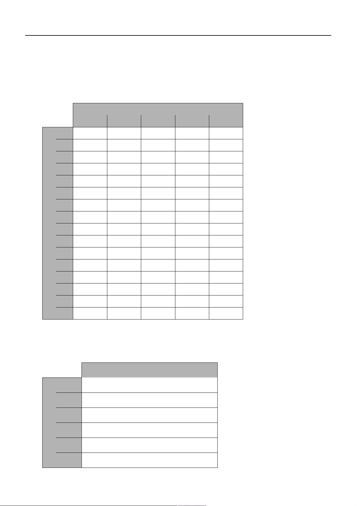
16. Anslutningsexempel (endast till 7 V)
☞ Den maximala kabellängden och armaturantalet beror på installationstypen och
kabelarean.
16.1 Installationsexempel linjestruktur
A: max. kabellängd se tabell
B: Nätdel
Q: Area in mm
2
0,5 0,75 1 1,5 2,5
1 40 m 60 m 80 m 120 m 200 m
2 20 m 30 m 40 m 60 m 100 m
3 14 m 20 m 25 m 40 m 70 m
4 10 m 15 m 20 m 30 m 50 m
5 8 m 12 m 15 m 25 m 40 m
6 7 m 10 m 14 m 22 m 35 m
7 5 m 8 m 12 m 19 m 31 m
8 5 m 8 m 11 m 16 m 27 m
9 5 m 7 m 10 m 12 m 20 m
10 4 m 6 m 8 m 12 m 20 m
11 4 m 6 m 8 m 12 m 20 m
N: Antalet armaturer
12 4 m 5 m 7 m 11 m 18 m
13 3 m 5 m 7 m 10 m 17 m
14 3 m5 m6 m9 m16 m
15 3 m4 m6 m9 m15 m
16 2 m4 m5 m8 m14 m
16.2 Installationsexempel stjärnform
A: max. kabellängd se tabell
B: Nätdel, max. 12 armaturer
L: maximal kabellängd i m
0,25 20
2
0,5 40
0,75 60
1 80
1,5 120
Q: Area in mm
2,5 200
ZMI_001_2030039477-ACEX9001_#SSV_#AQU_#V1.fm
- 51 -
Page 65

0Čeština
CS
síťový díl
Obrázky najdete v německém návodu k montáži a obsluze.
0 Seznam
1. Zkratky a jednotky . . . . . . . . . . . . . . . . . . . . . . . . . . . . . . . . . . . . 53
2. Vysvětlení značek. . . . . . . . . . . . . . . . . . . . . . . . . . . . . . . . . . . . . 53
3. Záruka . . . . . . . . . . . . . . . . . . . . . . . . . . . . . . . . . . . . . . . . . . . . . 53
4. Důležité informace . . . . . . . . . . . . . . . . . . . . . . . . . . . . . . . . . . . . 54
Popis produktu
5. Použití. . . . . . . . . . . . . . . . . . . . . . . . . . . . . . . . . . . . . . . . . . . . . . 54
6. Technické údaje . . . . . . . . . . . . . . . . . . . . . . . . . . . . . . . . . . . . . . 54
7. Rozměry . . . . . . . . . . . . . . . . . . . . . . . . . . . . . . . . . . . . . . . . . . . . 55
8. Skladování . . . . . . . . . . . . . . . . . . . . . . . . . . . . . . . . . . . . . . . . . . 55
9. Nejdůležitější charakteristické parametry . . . . . . . . . . . . . . . . . . . 55
10. Normy . . . . . . . . . . . . . . . . . . . . . . . . . . . . . . . . . . . . . . . . . . . . . . 55
Montáž, funkce a uvádìní do provozu
11. Provozní pokyny. . . . . . . . . . . . . . . . . . . . . . . . . . . . . . . . . . . . . . 55
12. Montáž/Demontáž . . . . . . . . . . . . . . . . . . . . . . . . . . . . . . . . . . . . 56
13. Napojení . . . . . . . . . . . . . . . . . . . . . . . . . . . . . . . . . . . . . . . . . . . . 56
14. Chování v případě zkratu a přetížení . . . . . . . . . . . . . . . . . . . . . . 57
15. Pojistky . . . . . . . . . . . . . . . . . . . . . . . . . . . . . . . . . . . . . . . . . . . . . 57
16. Příklad připojení . . . . . . . . . . . . . . . . . . . . . . . . . . . . . . . . . . . . . . 58
ZMI_001_2030039477-ACEX9001_#SCS_#AQU_#V1.fm
- 52 -
Page 66
1. Zkratky a jednotky
U
výstup
Lvnější vodič
N nulový vodič
RCD Residual Current Protective Device,
SELV Safety Extra Low Voltage, bezpečné nízké napětí
EA-Nr. Evropské číslo zboží
FAR-Best.-Nr. Objednací číslo Franke Aquarotter
Umrechnung 1 mm = 0,03937 palce
Všechny délkové údaje na obrázcích jsou uvedeny v mm.
výstupní napětí
proudový chránič
1 palec = 25,4 mm
2. Vysvětlení značek
Varování!
Zanedbání těchto pokynů může mít za následek ohrožení života nebo zranění osob.
Pozor!
Zanedbání těchto pokynů může mít za následek způsobení věcných škod.
☞ Důležité!
Zanedbání těchto pokynů může mít za následek způsobení funkčních poruch
daného produktu.
☞ Užitečné informace pro optimální zacházení s daným produktem.
3. Záruka
Ručení platí v rozsahu všeobecných dodacích a obchodních podmínek.
Používejte pouze originální náhradní díly!
ZMI_001_2030039477-ACEX9001_#SCS_#AQU_#V1.fm
- 53 -
Page 67

4. Důležité informace
• Montáž, uvádění do provozu a údržbu smí vykonávat výhradně jen patřičně kvalifikovaný odborník, podle společně dodaného návodu, a v souladu se zákonnými
předpisy a s uznávanými technickými pravidly.
• Dodržujte podmínky připojení stanovené místním dodavatelem vody a elektrické
energie.
• Veškeré práce vykonávejte ve stavu bez napětí.
•Změny jsou vyhrazeny.
5. Použití
Síťový díl podle výrobkové normy pro elektromagnetickou kompatibilitu a podle
normy pro bezpečnost . Napájení stabilizovaným stejnosměrným proudem.
Konstrukční provedení s pouzdrem z umělé hmoty, pro montáž na nosnou lištu.
Provedení odolné proti zkratu, s pružinovými svorkami. S bezpečnostním odpojením
pro napojené bistabilní magnetické ventily. Maximální délka kabelu je 10 metrů při
průřezu kabelu 0,32 mm².
6. Technické údaje
Normy/schválení
Bezpečnost EN 60335-1
EMV EN 55022
Vstup: 100-240 V st / 50-60 Hz
Rozsah napětí: 85-264 V st
Výstupní napětí: 44 až 66 Hz
EN 60950-1
EN 61558-2-16
EN 55024
EN 61000-3-2
EN 61000-3-3
EN 61000-6-2
EN 61000-6-3
EN 61204-3
RoHS
Vstupní proud: typ 1,05 A při 230 V st
Výstup:
Výstupní napětí: 6,75-7,5 V / 12-14 V
Výstupní proud: 4 A
Zvlnění: < 150 mVšš (při šířce pásma 20 MHz)
- 54 -
ZMI_001_2030039477-ACEX9001_#SCS_#AQU_#V1.fm
Page 68

Krytí: IP 20
Teplota prostředí: -25°C až +55°C
Skladovací teplota: -40°C až +85°C
Signalizace LED: Zelená kontrolka LED
Zvláštnosti: Odolné proti zkratu a proti chodu naprázdno
7. Rozměry
8. Skladování
přípustná skladovací teplota: -40 °C ... + 85 °C
přípustná vlhkost vzduchu při
skladování:
při dlouhodobém skladování:
30 ... 95 % relativní vlhkost, při uvádění do
provozu se nesmí vyskytovat žádná
kondenzace
Provozní prostředky se zabudovanými
kondenzátory se musejí přinejmenším vždy po
2 letech připojit po dobu min. 5 minut na síťové
napětí.
9. Nejdůležitější charakteristické parametry
• Širokorozsahový střídavý (AC) vstup bez přepínání
•Třída ochrany 2
• na primární straně je chráněné s použitím vnitřního jištění
• Je možné přepínat mezi 7 V a 12 V.
• Montáž pro nosnou lištu podle normy EN 50022
10. Normy
Elektrická bezpečnost je poskytnutá na základě konstrukce zařízení podle normy
EN 60950 (VDE 0805). Odpovídá požadavkům a normám ke shodě s evropskými
směrnicemi a nese značku CE.
11. Provozní pokyny
Nesmí se narušovat chlazení provozního prostředku. Je potřeba zajistit neomezený
přístup vzduchu a minimální odlehlost 15 mm od sousedních dílů.
Zapojování vodičů na připojovací svorky se smí uskutečňovat výhradně jen ve stavu
bez napětí. Na základě třídy krytí IP 20 je provoz tohoto zařízení přípustný výhradně
jen v suchých prostorech.
ZMI_001_2030039477-ACEX9001_#SCS_#AQU_#V1.fm
- 55 -
Page 69

12. Montáž/Demontáž
Pozor!
Systémový síťový díl se smí provozovat výhradně jen jako proudový okruh SELV. To
znamená, že systémové vedení nesmí být v žádném bodě uzemněné.
Montáž na nosnou lištu
12.1
Síťový díl na horní straně (a) zahákněte na nosnou lištu 35 mm podle normy
EN 50022.
12.2
Síťový díl na dolní straně přitiskněte proti nosné liště tak, až jazýček (b) zaskočí do
západky.
☞ Při řazení modulů v řadě vedle sebe je potřeba dodržovat minimální odlehlost
15 mm.
Demontáž z nosné lišty
12.3
Jazýček (b) zatáhněte směrem dolů, a síťový díl vyhákněte na spodní straně.
12.4
Síťový díl odtáhněte směrem nahoru.
13. Napojení
potřebné materiálové položky
K poskytnutí ze strany stavby:
• Rozvodná krabice pro vlhké prostředí (Ø 68 mm)
• Ochranný spínač chybového proudu (RCD / FI)
• Prázdná trubka pro připojovací kabel (Ø 10 mm)
• Prázdná trubka pro kabel
• dvoužilový kabel
☞ Proudové napájení umístěte vně vlhké oblasti do zvláštního prostoru, a zajistěte je
při použití ochranného spínače chybového proudu (RCD / FI).
13.1
Před připojením síťového dílu ověřte příslušné provozní napětí (viz typový štítek).
13.2
Proudové napájení připojte na svorky „vstup“ „L“ a „N“ (a).
13.3
Armatury připojte na svorky „výstup“ + a - (b).
+ … červený
– … černý
- 56 -
ZMI_001_2030039477-ACEX9001_#SCS_#AQU_#V1.fm
Page 70

Použijte následující připojovací kabel:
Na primární straně (230 VAC):
Používejte výhradně jen vhodný instalační kabel podle předpisů VDE (například typ
NYM 3×1,5 mm²).
Na sekundární straně (7 VDC/ 12 VDC):
Používejte výhradně jen originální připojovací kabel (objednací číslo FAR
2030010982).
jen pro 7 V:
Odpor přes celou délku kabelu (od síťového dílu k armatuře) musí být menší než
3,4 .
Průřez je potřeba volit podle délky vedení.
13.4
Pro každou armaturu nainstalujte jednu rozvodnou krabici pro vlhké prostředí (a).
13.5
Od rozvodné krabice pro vlhké prostředí až ke skřínce pro zabudování do stěny
položte prázdnou trubku (c; Ø 10 mm).
13.6
Dvoužilový kabel (b) položte do prázdné trubky, a prostrčte jej od rozvodné krabice
pro vlhké prostředí k rozvodné krabici pro vlhké prostředí.
13.7
Připojovací kabel (d) pro armaturu prostrčte přes prázdnou trubku (c).
☞ Zástrčka musí být pro armaturu dobře přístupná.
13.8
Připojovací kabel (d) napojte do rozvodné krabice pro vlhké prostředí.
13.9
Rozvodnou krabici pro vlhké prostředí uzavřete ochrannou krytkou (e).
13.10
Prodlužovací kabel spojte s armaturou.
14. Chování v případě zkratu a přetížení
V případě zkratu při síťovém provozu zůstane výstup odpojený. Uváděné prahové
hodnoty napětí pro připojení a pro odpojení platí po zkratu teprve až po odpojení napětí
na primární straně, nebo až po opětovném dosažení prahové hodnoty napětí o velikosti
7V.
15. Pojistky
Pozor!
Síťový díl je vnitřně na primární straně jištěný s použitím pojistky 1,6 AT/250 V.
Pokud dojde k rozpojení této pojistky, tak s největší pravděpodobností došlo k
poruše zařízení.
ZMI_001_2030039477-ACEX9001_#SCS_#AQU_#V1.fm
- 57 -
Page 71

16. Příklad připojení (jen pro 7 V)
☞ Maximální délka kabelu a počet armatur se odvíjí od způsobu instalace a průměru
kabelu.
16.1 Příklad instalace – zapojení do řady
A: max. délka kabelu, viz tabulka
B: síťový dí
Q: Průměr v mm
2
0,5 0,75 1 1,5 2,5
1 40 m 60 m 80 m 120 m 200 m
2 20 m 30 m 40 m 60 m 100 m
3 14 m 20 m 25 m 40 m 70 m
4 10 m 15 m 20 m 30 m 50 m
5 8 m 12 m 15 m 25 m 40 m
6 7 m 10 m 14 m 22 m 35 m
7 5 m 8 m 12 m 19 m 31 m
8 5 m 8 m 11 m 16 m 27 m
9 5 m 7 m 10 m 12 m 20 m
10 4 m 6 m 8 m 12 m 20 m
11 4 m 6 m 8 m 12 m 20 m
N: Poèet armatur
12 4 m 5 m 7 m 11 m 18 m
13 3 m 5 m 7 m 10 m 17 m
14 3 m5 m6 m9 m16 m
15 3 m4 m6 m9 m15 m
16 2 m4 m5 m8 m14 m
16.2 Příklad instalace – zapojení do řady
A: max. délka kabelu, viz tabulka
B: síťový dí, maximálnì 12 armatur
L: maximální délka kabelu v m
0,25 20
2
0,5 40
0,75 60
1 80
1,5 120
Q: Průměr v mm
2,5 200
ZMI_001_2030039477-ACEX9001_#SCS_#AQU_#V1.fm
- 58 -
Page 72

0Suomi
FI
Verkkolaite
Kuvat löytyvät saksankielisestä asennus- ja käyttöohjeesta.
0 Innehållsförteckning
1. Lyhenteet ja yksiköt . . . . . . . . . . . . . . . . . . . . . . . . . . . . . . . . . . . 60
2. Merkkien selitys . . . . . . . . . . . . . . . . . . . . . . . . . . . . . . . . . . . . . . 60
3. Takuu . . . . . . . . . . . . . . . . . . . . . . . . . . . . . . . . . . . . . . . . . . . . . . 60
4. Tärkeitä ohjeita . . . . . . . . . . . . . . . . . . . . . . . . . . . . . . . . . . . . . . . 61
Tuotteen kuvaus
5. Käyttö . . . . . . . . . . . . . . . . . . . . . . . . . . . . . . . . . . . . . . . . . . . . . . 61
6. Tekniset tiedot. . . . . . . . . . . . . . . . . . . . . . . . . . . . . . . . . . . . . . . . 61
7. Mitat . . . . . . . . . . . . . . . . . . . . . . . . . . . . . . . . . . . . . . . . . . . . . . . 62
8. Varastointi. . . . . . . . . . . . . . . . . . . . . . . . . . . . . . . . . . . . . . . . . . . 62
9. Tärkeimmät erityispiirteet . . . . . . . . . . . . . . . . . . . . . . . . . . . . . . . 62
10. Standardit . . . . . . . . . . . . . . . . . . . . . . . . . . . . . . . . . . . . . . . . . . . 62
Asennus, toiminta ja käyttöönotto
11. Käyttöohjeita. . . . . . . . . . . . . . . . . . . . . . . . . . . . . . . . . . . . . . . . . 62
12. Asennus/purkaminen . . . . . . . . . . . . . . . . . . . . . . . . . . . . . . . . . . 63
13. Liitäntä . . . . . . . . . . . . . . . . . . . . . . . . . . . . . . . . . . . . . . . . . . . . . 63
14. Oikosulku- ja liikakuormituskäyttäytyminen . . . . . . . . . . . . . . . . . 64
15. Sulakkeet . . . . . . . . . . . . . . . . . . . . . . . . . . . . . . . . . . . . . . . . . . . 64
16. Liitäntäesimerkki (vain 7 V) . . . . . . . . . . . . . . . . . . . . . . . . . . . . . 65
ZMI_001_2030039477-ACEX9001_#SFI_#AQU_#V1.fm
- 59 -
Page 73

1. Lyhenteet ja yksiköt
U
out
L ulkojohtimen
N neutraali
RCD Residual Current Protective Device,
SELV Safety Extra Low Voltage, pienvirtasuoja
EA-Nr. Eurooppalainen tuotenumero
FAR-Best.-Nr. Franke Aquarotter -tilausnumero
Umrechnung 1 mm = 0,03937 tuumaa
Piirrosten kaikkien pituustietojen yksikkö on mm.
lähtöjännite
vikavirtasuojakytkin
1 tuuma = 25,4 mm
2. Merkkien selitys
Varoitus!
Huomioon ottamatta jättäminen voi aiheuttaa hengenvaaran tai ruumiinvamman.
Huomio!
Huomioon ottamatta jättäminen voi aiheuttaa aineellisia vahinkoja.
☞ Tärkeää!
Huomioon ottamatta jättäminen voi aiheuttaa tuotteen toimintahäiriöitä.
☞ Hyodyllista tietoa parhaaseen mahdolliseen tyoskentelyyn tuotteen parissa.
3. Takuu
Vastuu siirtyy yleisten toimitus- ja kauppaehtojen mukaisesti.
Käytä vain alkuperäisvaraosia!
- 60 -
ZMI_001_2030039477-ACEX9001_#SFI_#AQU_#V1.fm
Page 74

4. Tärkeitä ohjeita
• Asennus, käyttöönotto ja huolto vain ammattilaisten tekemänä mukana toimitettujen ohjeiden mukaan, jotka täyttävät lain määräykset ja yleisesti hyväksytyt
tekniset normit.
• Pidä kiinni myös paikallisten vesi- ja energiantoimittajien liitäntäehdoista.
• Kaikki työt on tehtävä jännitteettömälle järjestelmälle.
• Pidätetään oikeus muutoksiin.
5. Käyttö
Verkkolaite on EMC-tuotestandardin sekä turvallisuusstandardien mukainen.
Muovikotelolla hattukiskolle asennusta varten. Oikosulunkestävä toteutus jousipinteillä.
Turvakatkaisu kytketyille kaksiasentoisille magneettiventtiileille. Kaapelin maksimipituus
10 m, kun kaapelin poikkipinta-ala on 0,32 mm².
6. Tekniset tiedot
Standardit/hyväksynnät
Turvallisuus EN 60335-1
EN 60950-1
EN 61558-2-16
EMC EN 55022
EN 55024
EN 61000-3-2
EN 61000-3-3
EN 61000-6-2
EN 61000-6-3
EN 61204-3
RoHS
Tulo: 100-240 V ac / 50-60 Hz
Jännitealue: 85-264 V ac
Taajuus: 44 bis 66 Hz
Tulovirta: tyyppi 1,05 A jännitteellä 230 V ac
Lähtö:
Lähtöjännite: 6,75-7,5 V / 12-14 V
Lähtövirta: 4 A
Aaltoisuus: < 150 mVpp (20 MHz: n kaistanleveydellä)
Suojausluokka: IP 20
Ympäristön lämpötila: -25°C bis +55°C
Varastointilämpötila: -40°C bis +85°C
LED-merkkivalo: vihreä LED
ZMI_001_2030039477-ACEX9001_#SFI_#AQU_#V1.fm
Erityispiirteitä: Oikosulun ja avoimeen kiertoon proof
- 61 -
Page 75

7. Mitat
8. Varastointi
sallittu varastointilämpötila: -40 °C ... + 85 °C
sallittu ilmankosteus:
pitkäaikaisessa varastoinnissa:
30 ... 95 % suhteellinen kosteus; käyttöönoton
aikana ei saa olla kondensoitunutta kosteutta.
Laitteen sisäänrakennetut kondensaattorit on
kytkettävä vähintään joka toinen vuosi
vähintään 5 minuutin ajaksi
verkkojännitteeseen.
9. Tärkeimmät erityispiirteet
• laaja-alainen AC-sisääntulo ilman vaihtokytkentää
• Suojausluokka 2
• ensisijaisesti suojattu sisäisellä sulakkeella
• Jännitteeksi voidaan valita joko 7 V tai 12 V.
• Asennus hattukiskoon standardin EN 50022 mukaisesti
10. Standardit
Sähköturvallisuus on taattu standardin EN 60950 (VDE 0805) mukaisella laiterakenteella. Se on EU:n konedirektiivien vaatimusten mukainen ja saa käyttää CEmerkintää.
11. Käyttöohjeita
Laitteen jäähdytystä ei saa estää. Esteetön ilmankulku ja 15 mm:n minimietäisyys
lähellä olevista osista on varmistettava.
Liittimien johdotuksen saa tehdä ainoastaan jännitteettömässä tilassa. Suojaustavan
IP 20 perusteella laitteen käyttö on sallittu vain kuivissa tiloissa.
- 62 -
ZMI_001_2030039477-ACEX9001_#SFI_#AQU_#V1.fm
Page 76

12. Asennus/purkaminen
Huomio!
Järjestelmän verkkolaitetta saa käyttää vain SELV-virtapiirissä. Järjestelmän johtoja
ei siis saa maadoittaa missään kohtaa.
Asennus hattukiskolle
12.1
Laita verkkolaite ylös (a) 35 mm:n hattukiskolle EN 50022:n mukaisesti.
12.2
Paina verkkolaitetta alas hattukiskoa kohti, kunnes sidekisko (b) lukittuu.
☞ Mikäli moduulit asetetaan jonoon, on niiden välillä oltava 15 mm:n minimietäisyys.
Hattukiskojen purkaminen
• Vedä sidekiskoa (b) alaspäin ja ripusta verkkolaite alas.
• Vedä verkkolaite ylös.
13. Liitäntä
tarvittavat materiaalit
Asiakkaan varattava:
• kostean tilan jakorasia (Ø 68 mm)
• vikavirtasuojakatkaisin (RCD)
• suojaputki liitäntäkaapelille (Ø 10 mm)
• suojaputki kaapelille
• 2-johtiminen kaapeli
☞ Virtalähde tulee sijoittaa kostean tilan ulkopuolelle erilliseen tilaan ja suojata vikavir-
tasuojakatkaisimella (RCD).
13.1
Tarkista ennen verkkolaitteen liittämistä sen käyttöjännite (katso tyyppikilvestä).
13.2
Kytke virransyöttö tuloliittimiin L ja N (a).
13.3
Kytke hanat lähtöliittimiin + ja - (b).
+ … punainen
– … musta
ZMI_001_2030039477-ACEX9001_#SFI_#AQU_#V1.fm
- 63 -
Page 77

Käytä seuraavia liitäntäkaapeleita:
Ensiöpuoli (230 VAC):
Käytä ainoastaan sopivaa VDE:n (esim. NYM 3x1,5 mm²) mukaista kaapelia.
Toisiopuoli (7 VDC/ 12 VDC):
Käytä ainoastaan alkuperäistä liitäntäkaapelia (FAR-tilausnro 2030010982).
vain 7 V:
Vastuksen koko kaapelin pituudella (verkkolaitteesta hanaan) on oltava alle
3,4 ohmia.
Poikkipinta-ala on valittava johdon pituuden mukaan.
13.4
Kutakin hanaa kohden on asennettava yksi kostean tilan jakorasia (a).
13.5
Aseta suojaputki (c; Ø 10 mm) kostean tilan jakorasiasta seinässä olevaan pistorasiaan.
13.6
Aseta 2-johtiminen kaapeli (b) suojaputkeen ja kuljeta se kostean tilan jakorasiasta
toiseen.
13.7
Työnnä hanaan tarkoitettu liitäntäkaapeli (d) suojaputken (c) läpi.
☞ Pistokkeen on oltava käden ulottuvilla hanan luona.
13.8
Kytke liitäntäkaapeli (d) kostean tilan jakorasiaan.
13.9
Sulje kostean tilan jakorasia suojakannella (e).
13.10
Liitä jatkokaapeli hanaan.
14. Oikosulku- ja liikakuormituskäyttäytyminen
Oikosulun sattuessa verkkokäytössä lähtö pysyy vapaana. Mainitut käynnistyksen ja
katkaisun jänniterajat ovat oikosulun jälkeen voimassa vasta ensiöpuolen jännitteen
vapautuksen tai 7 voltin jänniterajan uudelleensaavuttamisen jälkeen.
15. Sulakkeet
Huomio!
Verkkolaite on ensiöpuolelta suojattu 1,6 AT/250 V:n sulakkeella. Kun tämä sulake
laukeaa, on kyseessä todennäköisimmin laitevika.
- 64 -
ZMI_001_2030039477-ACEX9001_#SFI_#AQU_#V1.fm
Page 78

16. Liitäntäesimerkki (vain 7 V)
☞ Kaapelin enimmäispituus ja liitinten lukumäärä riippuu asennustavasta ja kaapelin
poikkileikkauksesta.
16.1 Asennusesimerkki linjarakenne
A: Kaapelin enimmäispituus ks. taulukko
B: Verkkolaite
Q: Poikkileikkaus mm
2
0,5 0,75 1 1,5 2,5
1 40 m 60 m 80 m 120 m 200 m
2 20 m 30 m 40 m 60 m 100 m
3 14 m 20 m 25 m 40 m 70 m
4 10 m 15 m 20 m 30 m 50 m
5 8 m 12 m 15 m 25 m 40 m
6 7 m 10 m 14 m 22 m 35 m
7 5 m 8 m 12 m 19 m 31 m
8 5 m 8 m 11 m 16 m 27 m
9 5 m 7 m 10 m 12 m 20 m
10 4 m 6 m 8 m 12 m 20 m
11 4 m 6 m 8 m 12 m 20 m
N: Liitinten lukumäärä
12 4 m 5 m 7 m 11 m 18 m
13 3 m 5 m 7 m 10 m 17 m
14 3 m5 m6 m9 m16 m
15 3 m4 m6 m9 m15 m
16 2 m4 m5 m8 m14 m
16.2 Asennusesimerkki linjarakenne
A: Kaapelin enimmäispituus ks. taulukko
B: Verkkolaite,
maks. 12 hanaa
L: kaapelin enimmäispituus m
2
0,25 20
0,5 40
0,75 60
1 80
1,5 120
2,5 200
ZMI_001_2030039477-ACEX9001_#SFI_#AQU_#V1.fm
Q: Poikkileikkaus mm
- 65 -
Page 79

0Русский
RU
Сетевой блок питания
Рисунки приведены в инструкции по монтажу и эксплуатации на немецком
языке.
0 Содержание
1. Сокращения и единицы измерения. . . . . . . . . . . . . . . . . . . . . . 67
2. Объяснение условных знаков . . . . . . . . . . . . . . . . . . . . . . . . . . 67
3. Гарантия . . . . . . . . . . . . . . . . . . . . . . . . . . . . . . . . . . . . . . . . . . . 67
4. Важные указания . . . . . . . . . . . . . . . . . . . . . . . . . . . . . . . . . . . . 68
Описание изделия
5. Применение. . . . . . . . . . . . . . . . . . . . . . . . . . . . . . . . . . . . . . . . . 68
6. Технические данные . . . . . . . . . . . . . . . . . . . . . . . . . . . . . . . . . . 68
7. Размеры. . . . . . . . . . . . . . . . . . . . . . . . . . . . . . . . . . . . . . . . . . . . 69
8. Хранение . . . . . . . . . . . . . . . . . . . . . . . . . . . . . . . . . . . . . . . . . . . 69
9. Основные характеристики . . . . . . . . . . . . . . . . . . . . . . . . . . . . . 69
10. Стандарты . . . . . . . . . . . . . . . . . . . . . . . . . . . . . . . . . . . . . . . . . . 69
Монтаж, принцип действия и ввод в эксплуатацию
11. Указания по эксплуатации . . . . . . . . . . . . . . . . . . . . . . . . . . . . . 70
12. Монтаж/демонтаж. . . . . . . . . . . . . . . . . . . . . . . . . . . . . . . . . . . . 70
13. Подключение. . . . . . . . . . . . . . . . . . . . . . . . . . . . . . . . . . . . . . . . 70
14. Поведение при коротком замыкании и перегрузке . . . . . . . . . 72
15. Предохранители . . . . . . . . . . . . . . . . . . . . . . . . . . . . . . . . . . . . . 72
16. Пример подключения (только для
7 B) . . . . . . . . . . . . . . . . . . . 72
ZMI_001_2030039477-ACEX9001_#SRU_#AQU_#V1.fm
- 66 -
Page 80

1. Сокращения и единицы измерения
U
out
L Внешний провод
N Нулевой провод
RCD (УЗО-Д) Residual Current Protective Device,
SELV (БСНН) Safety Extra Low Voltage, безопасное
EA-Nr. Европейский артикульный номер
FAR-Best.-Nr. Номер для заказа Franke Aquarotter
Перевод из одной
системы мер в другую
Все значения длины на рисунках указаны в миллиметрах.
Выходное напряжение
устройство защитного отключения
сверхнизкое напряжение
1 мм = 0,03937 дюйма
1 дюйм = 25,4 мм
2. Объяснение условных знаков
Предупреждение!
Несоблюдение данного указания может привести к опасности для жизни или
телесным повреждениям.
Внимание!
Несоблюдение данного указания может привести к материальному ущербу.
☞ Wichtig!
Несоблюдение данного указания может привести к неполадкам в работе
изделия.
☞ Полезная информация по оптимальному обращению с изделием.
3. Гарантия
Производитель несет ответственность в соответствии с Общими условиями
поставки и заключения торговых сделок.
Используйте только оригинальные запчасти!
ZMI_001_2030039477-ACEX9001_#SRU_#AQU_#V1.fm
- 67 -
Page 81

4. Важные указания
• Монтаж, ввод в эксплуатацию и техническое обслуживание должен
выполнять только специалист в соответствии с прилагаемой инструкцией,
предписаниями законов и общепризнанными правилами техники
безопасности.
• Соблюдайте технические условия подключения местных предприятий,
отвечающих за водоснабжение и энергоснабжение.
• Выполняйте все работы при отключенном напряжении.
• Право на внесение изменений сохраняется.
5. Применение
Сетевой блок питания по производственному стандарту по электромагнитной
совместимости и стандарту по безопасности. Подача стабилизированного
постоянного тока. Пластмассовым корпусом для монтажа на монтажной шине.
Исполнение с защитой от коротких замыканий, с пружинящими зажимами. С
функцией аварийного отключения подключенных бистабильных электромагнитных клапанов. Макс. длина кабеля 10 м при поперечном сечении
0,32 мм².
6. Технические данные
Стандарты/допуски
Безопасность EN 60335-1
ЭМС EN 55022
Вход: 100-240 В перем. тока/50-60 Гц
Диапазон напряжения: 85-264 В перем. тока
Частота: 44-66 Гц
EN 60950-1
EN 61558-2-16
EN 55024
EN 61000-3-2
EN 61000-3-3
EN 61000-6-2
EN 61000-6-3
EN 61204-3
RoHS
Входной ток: Тип 1,05 А при 230 В перем. тока
Выход:
Выходное напряжение: 6,75-7,5 В / 12-14 В
Выходной ток:4 A
Пульсация: < 150 мВпп (при ширине полосы 20 МГц)
- 68 -
ZMI_001_2030039477-ACEX9001_#SRU_#AQU_#V1.fm
Page 82

Степень защиты:IP 20
Температура окружающей
среды:
Температура хранения: От -40° C до +85° C
Сигнализация светодиодным
индикатором:
Особенности: С защитой от коротких замыканий и
7. Размеры
8. Хранение
Допустимая температура
хранения:
Допустимая влажность
воздуха
:
От -25° C до +55° C
Зеленый светодиодный индикатор
холостого хода
-40 °C ... + 85 °C
30 ... 95 % (относительная влажность); при
вводе в эксплуатацию конденсация должна
отсутствовать.
При длительном хранении:
На электрооборудование со встроенными
конденсаторами не реже, чем через каждые
2 года необходимо подавать сетевое
напряжение в течение как минимум 5 минут.
9. Основные характеристики
• Вход переменного тока большого радиуса действия без переключения
• Класс защиты 2
• Защита посредством внутреннего предохранителя в первичной обмотке
• Возможно переключение между 7 В и 12 В.
• Монтаж на монтажной шине согласно EN 50022
10. Стандарты
Электрическая безопасность обеспечивается за счет конструкции устройства
по EN 60950 (VDE 0805). Устройство отвечает требованиям и стандартам
соответствия качества и безопасности ЕС и имеет знак CE.
ZMI_001_2030039477-ACEX9001_#SRU_#AQU_#V1.fm
- 69 -
Page 83

11. Указания по эксплуатации
Запрещается нарушать охлаждение электрооборудования. Необходимо
обеспечить беспрепятственную подачу воздуха и минимальное расстояние
15 мм до соседних узлов.
Монтаж соединительных клемм разрешается выполнять только в обесточенном состоянии. В соответствии со степенью защиты IP 20 устройство
разрешается эксплуатировать только в сухих помещениях.
12. Монтаж/демонтаж
Внимание!
Системный сетевой блок питания разрешается эксплуатировать только в
качестве электрической цепи БСНН. Это означает, что системный кабель
запрещается заземлять.
Монтаж на монтажных шинах
12.1
Навесьте сетевой блок питания сверху (a) на монтажную шину 35 мм по
EN 50022.
12.2
Прижмите сетевой блок питания снизу к монтажной шине так, чтобы язычок (b)
защелкнулся.
☞ При установке модулей в ряд необходимо соблюдать минимальное расстояние
15 мм.
Демонтаж с монтажных шин
12.3
Потяните язычок (b) вниз и снимите сетевой блок питания снизу с язычка.
12.4
Снимите сетевой блок питания по направлению вверх.
13. Подключение
Необходимые материалы
предоставляются заказчиком:
• Распределительная коробка для сырых помещений (диаметр 68 мм)
• Устройство защитного отключения по дифференциальному току (УЗО-Д)
• Защитная труба для кабеля для подключения (диаметр 10 мм)
• Защитная труба для кабеля
•2-жильный кабель
☞ Разместите источник питания за пределами ванной комнаты в отдельном
помещении и защитите его с помощью устройства защитного отключения по
дифференциальному току (УЗО-Д).
- 70 -
ZMI_001_2030039477-ACEX9001_#SRU_#AQU_#V1.fm
Page 84

13.1
Перед подключением сетевого блока питания проверьте соответствующее
рабочее напряжение (см. заводскую табличку).
13.2
Подключите блок питания к клеммам Input L и N (a).
13.3
Подключите смесители к клеммам Output + и - (b).
+ … красный
– … черный
Используйте следующие кабели для подключения:
В первичной обмотке (230 В перем. тока):
Используйте только подходящие инсталляционные кабели по VDE (например,
NYM 3×1,5 мм²).
Во вторичной обмотке (7 В пост. тока / 12 В пост. тока):
Используйте оригинальный кабель для подключения (№ для заказа
FAR 2030010982).
Только для 7 B:
Сопротивление по всей длине кабеля
смесителя) должно быть меньше 3,4 Ом.
Поперечное сечение следует выбирать в соответствии с длиной кабеля.
(от сетевого блока питания до
13.4
Для каждого смесителя установите распределительную коробку для сырых
помещений (a).
13.5
Проложите защитную трубу (c; диаметр 10 мм) от распределительной коробки
для сырых помещений до скрытого монтажного короба.
13.6
Проложите 2-жильный кабель (b) в защитной трубе и продвиньте его от распределительной коробки для сырых помещений до распределительной коробки
для сырых помещений.
13.7
Вставьте кабель для подключения (d) смесителя через защитную трубу (c).
☞ К штекеру для смесителя должен обеспечиваться свободный доступ.
13.8
Подсоедините кабель для подключения (d) в распределительной коробке для
сырых помещений.
13.9
Закройте распределительную коробку для сырых помещений защитной
панелью (e).
13.10
Соедините удлинительный кабель со смесителем.
ZMI_001_2030039477-ACEX9001_#SRU_#AQU_#V1.fm
- 71 -
Page 85

14. Поведение при коротком замыкании и перегрузке
При коротком замыкании при работе от сети выход остается отключенным.
Указанное пороговое напряжение для включения и выключения применяется
после короткого замыкания только после отключения напряжения в первичной
обмотке или повторного достижения порогового напряжения 7 В.
15. Предохранители
Внимание!
Сетевой блок питания защищен внутренним предохранителем 1,6 AT/250 В в
первичной обмотке. Срабатывание этого предохранителя означает высокую
степень вероятности повреждения устройства.
16. Пример подключения (только для 7 B)
☞ Максимальная длина кабеля и количество смесителей зависит от типа
установки и поперечного сечения кабеля.
16.1 Пример установки: линейная структура
A: макс. длину кабеля см. в таблице
B: Сетевой блок питания
Q: поперечное сечение, мм2
0,5 0,75 1 1,5 2,5
1 40 m 60 m 80 m 120 m 200 m
2 20 m 30 m 40 m 60 m 100 m
3 14 m 20 m 25 m 40 m 70 m
4 10 m 15 m 20 m 30 m 50 m
5 8 m 12 m 15 m 25 m 40 m
6 7 m 10 m 14 m 22 m 35 m
7 5 m 8 m 12 m 19 m 31 m
8 5 m 8 m 11 m 16 m 27 m
9 5 m 7 m 10 m 12 m 20 m
10 4 m 6 m 8 m 12 m 20 m
N: Ilość armatur
11 4 m 6 m 8 m 12 m 20 m
12 4 m 5 m 7 m 11 m 18 m
13 3 m 5 m 7 m 10 m 17 m
14 3 m5 m6 m9 m16 m
15 3 m4 m6 m9 m15 m
16 2 m4 m5 m8 m14 m
- 72 -
ZMI_001_2030039477-ACEX9001_#SRU_#AQU_#V1.fm
Page 86

16.2 Пример установки: линейная структура
A: макс. длину кабеля см. в таблице
B: Сетевой блок питания,
Макс. 12 смесителей
L: максимальная длина кабеля в метрах
0,25 20
0,5 40
0,75 60
1 80
1,5 120
Q: поперечное сечение, мм2
2,5 200
ZMI_001_2030039477-ACEX9001_#SRU_#AQU_#V1.fm
- 73 -
Page 87

NotizenNotes / Notes / Notas / Annotazioni / Notities / Uwagi /
Notiser / Poznámky / Muistiinpanot / Примечания
- 74 -
ZMI_001_2030039477-ACEX9001_#SRU_#AQU_#V1.fm
Page 88

NotizenNotes / Notes / Notas / Annotazioni / Notities / Uwagi /
Notiser / Poznámky / Muistiinpanot / Примечания
ZMI_001_2030039477-ACEX9001_#SRU_#AQU_#V1.fm
- 75 -
Page 89

Australia
PR Kitchen and Water Systems Pty Ltd
Dandenong South VIC 3175
Phone +61 3 9700 9100
Austria
Franke GmbH
6971 Hard
Phone +43 5574 6735 0
Belgium & Luxembourg
Franke N.V.
9400 Ninove, Belgium
Phone +32 54 310 130
Czech Republic
Franke Aquarotter GmbH
14974 Ludwigsfelde, Germany
Phone +420 281 090 429
France
Franke GmbH
6971 Hard, Austria
Phone +33 800 909 216
Germany
Franke Aquarotter GmbH
14974 Ludwigsfelde
Phone +49 3378 818 530
Italy
Franke Water Systems AG
4663 Aarburg, Switzerland
Numero Verde 800 789 233
Middle East
Franke LLC
Ras Al Khaimah, United Arab Emirates
Phone +971 7 2034 700
Morocco
Franke Kitchen System SARL
21 000 Casablanca
Phone +212 522 674 200
Netherlands
Franke N.V.
9400 Ninove, Belgium
Phone +31 492 72 82 24
Poland
Franke Aquarotter GmbH
14974 Ludwigsfelde, Germany
Phone +48 22 711 6717
Portugal
Franke Portugal S.A.
2735-531 Cacém
Phone +351 21 426 9670
South Africa & Sub Saharan Africa
Franke South Africa
Durban, 4052
Phone + 27 31 450 6300
Spain
Franke GmbH
6971 Hard, Austria
Phone +43 5574 6735 211
Switzerland & Liechtenstein
Franke Water Systems AG
4663 Aarburg
Phone +41 62 787 3131
Tur key
Franke Mutfak ve Banyo Sistemleri
Sanayi ve Ticaret A.S.
41400 Gebze Kocaeli
Phone +90 262 644 6595
United Kingdom
Franke Sissons Ltd.
Barlborough S43 4PZ
Phone +44 1246 450 255
Dart Valley Systems Ltd.
Paignton TQ4 7TW
Phone +44 1803 529 021
EAST EUROPE
Bosnia Herzegovina | Bulgaria |
Croatia | Hungary | Latvia | Lithuania |
Romania | Russia | Serbia | Slovakia |
Slovenia | Ukraine
Franke Aquarotter GmbH
14974 Ludwigsfelde, Germany
Phone +49 3378 818 530
NORTH AMERICA
United States | Canada
Franke Kindred Canada Limited
Midland, ON L4R 4K9, Canada
Phone +1 855 446 5663
SCANDINAVIA & ESTONIA
Finland | Sweden | Norway |
Denmark | Estonia
Franke Finland Oy
76850 Naarajärvi, Finland
Phone +358 15 34 111
OTHER COUNTRIES
Franke GmbH
6971 Hard, Austria
Phone +43 5574 6735 0
www.franke.com
© Franke Technology and Trademark Ltd., Switzerland / 26.07.17 / 2030039569
 Loading...