


GB
IT
FR
DE
TR
Instructions for use and installation
Cooker Hood
Istruzioni per l’uso e l’installazione
Cappa
Mode d’emploi et installation
Hotte de Cuisine
Bedienungsanleitung und Einrichtung
Dunstabzugshaube
Kullanım ve montaj talimatları
Davlumbaz
FCR 708-H TC

INDEX
EN
RECOMMENDATIONS AND SUGGESTIONS ...................................................................................................................... |
3 |
CHARACTERISTICS.............................................................................................................................................................. |
4 |
INSTALLATION ...................................................................................................................................................................... |
5 |
USE......................................................................................................................................................................................... |
8 |
MAINTENANCE...................................................................................................................................................................... |
9 |
INDICE
IT
CONSIGLI E SUGGERIMENTI ............................................................................................................................................ |
13 |
CARATTERISTICHE ............................................................................................................................................................ |
14 |
INSTALLAZIONE.................................................................................................................................................................. |
15 |
USO ...................................................................................................................................................................................... |
18 |
MANUTENZIONE ................................................................................................................................................................. |
19 |
SOMMAIRE
FR
CONSEILS ET SUGGESTIONS .......................................................................................................................................... |
23 |
CARACTERISTIQUES ......................................................................................................................................................... |
24 |
INSTALLATION .................................................................................................................................................................... |
25 |
UTILISATION........................................................................................................................................................................ |
28 |
ENTRETIEN.......................................................................................................................................................................... |
29 |
INHALTSVERZEICHNIS
DE
EMPFEHLUNGEN UND HINWEISE |
....................................................................................................................................33 |
CHARAKTERISTIKEN.......................................................................................................................................................... |
34 |
MONTAGE............................................................................................................................................................................ |
35 |
BEDIENUNG......................................................................................................................................................................... |
38 |
WARTUNG............................................................................................................................................................................ |
39 |
IÇERIKLER |
TR |
TAVSIYELER VE ÖNERILER .............................................................................................................................................. |
43 |
ÖZELLIKLER ........................................................................................................................................................................ |
44 |
MONTAJ ............................................................................................................................................................................... |
45 |
KULLANIM ............................................................................................................................................................................ |
48 |
BAKIM................................................................................................................................................................................... |
49 |
2

RECOMMENDATIONS AND SUGGESTIONS
 The Instructions for Use apply to several versions of this appliance. Accordingly, you may find descriptions of individual features that do not apply to your specific appliance.
INSTALLATION
•The manufacturer will not be held liable for any damages resulting from incorrect or improper installation.
•The minimum safety distance between the cooker top and the extractor hood is 650 mm (some models can be installed at a lower height, please refer to the paragraphs on working dimensions and installation).
•Check that the mains voltage corresponds to that indicated on the rating plate fixed to the inside of the hood.
•For Class I appliances, check that the domestic power supply guarantees adequate earthing.
Connect the extractor to the exhaust flue through a pipe of minimum diameter 120 mm. The route of the flue must be as short as possible.
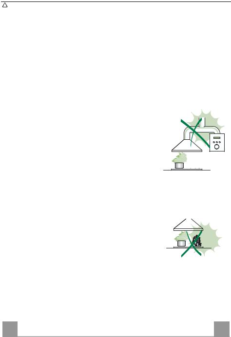
•Do not connect the extractor hood to exhaust ducts carrying combustion fumes (boilers, fireplaces, etc.).
•If the extractor is used in conjunction with non-electrical appliances (e.g. gas burning appliances), a sufficient degree of aeration must be guaranteed in the room in order to prevent the backflow of exhaust gas. The kitchen must have an opening communicating directly with the open air in order to guarantee the entry of clean air.
USE
• The extractor hood has been designed exclusively for domestic use to eliminate kitchen smells.
• Never use the hood for purposes other than for which it has been designed.
• Never leave high naked flames under the hood when it is in operation.
•Adjust the flame intensity to direct it onto the bottom of the pan only, making sure that it does not engulf the sides.
•Deep fat fryers must be continuously monitored during use: overheated oil can burst into flames.
•Do not flambè under the range hood; risk of fire
•This appliance is not intended for use by persons (including children) with reduced physical, sensory or mental capabilities, or lack of experience and knowledge, unless they have been given supervision or instruction concerning use of the appliance by a person responsible for their safety.
•Children should be supervised to ensure that they do not play with the appli-
ance.
MAINTENANCE
• Switch off or unplug the appliance from the mains supply before carrying out any maintenance work.
•Clean and/or replace the Filters after the specified time period (Fire hazard).
•Clean the hood using a damp cloth and a neutral liquid detergent.
The symbol  on the product or on its packaging indicates that this product may not be treated as household waste. Instead it shall be handed over to the applicable collection point for the recycling of electrical and electronic equipment. By ensuring this product is disposed of correctly, you will help prevent potential negative consequences for the environment and human health, which could otherwise be caused by inappropriate waste handling of this product. For more detailed information about recycling of this product, please contact your local city office, your household waste disposal service or the shop where you purchased the product.
EN
3
3

CHARACTERISTICS
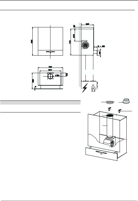
Dimensions
Min. |
Min. |
650mm 650mm |
|
Components
Ref. Q.ty Product components
11 Hood Body complete with: Controls, Light, Suction Unit, Filters, Lower Duct
7 |
1 |
PVC Pipe (fitted) |
8 |
1 |
Inclinable grid (fitted) |
9 |
1 |
Reduction flange ø 150-120 mm |
10 |
1 |
Metal cover |
|
|
|
Ref. |
Q.ty |
Assembly components |
11a |
2 |
SB 12/10 Plugs |
|
|
|
|
Q.ty |
Documents |
|
1 |
Instruction Manual |
10 |
9 |
11a
8
7
EN |
|
4 |
|
4 |
INSTALLATION
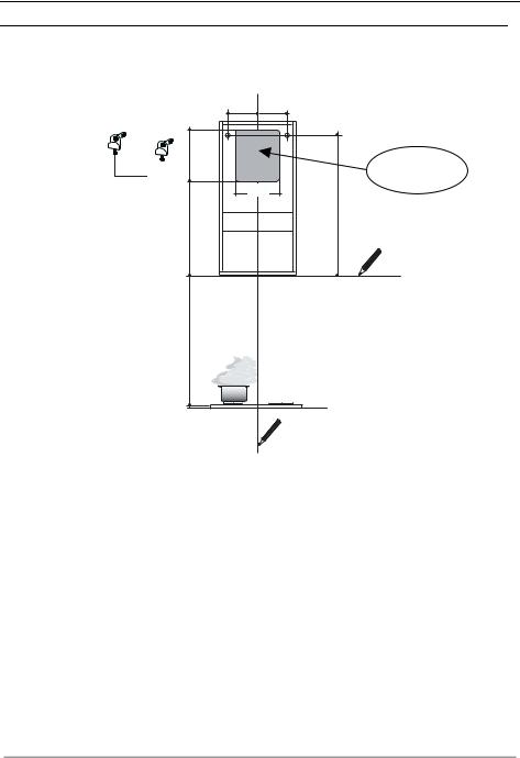
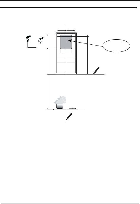
Boring the wall
If you want to use the hood in suction version with the air outlet at the back of the hood, make sure to follow the indications given below in the drawing for a correct boring operation of the air outlet opening.
|
230 |
230 |
11a |
275 |
|
|
|
|
|
|
250 |
|
|
658 |
|
442 |
|
|
650 mm min |
|
Rear air outlet zone
When installing the hood in recycling version it has to be taken into consideration that space remaining between the hood and the upper limit (ceiling or self) is at least 8-10 cm.
On the wall, trace:
•a vertical line up to the ceiling or top limit, at the centre of the area where you intend to fit the hood;
•a horizontal line at: 650 mm min. above the cooking hob;
•As shown, mark a reference point at 658 mm above the horizontal reference line, and at 230 mm to the right of the vertical reference line.
•Repeat this operation on the opposite side, checking levelling.
•Drill the points marked using a ø 12 mm bit
•Insert plugs with screws and brackets 11a in the holes then tighten them.
EN |
|
5 |
|
5 |
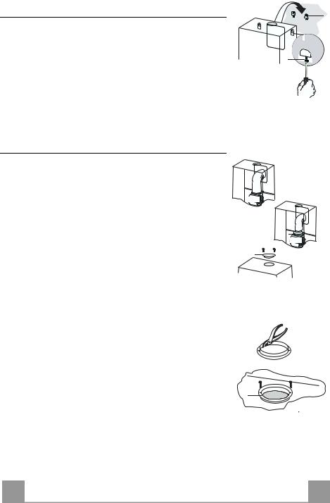
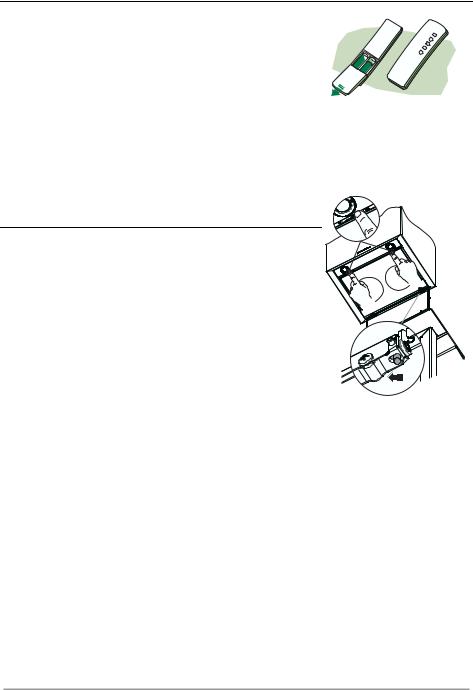
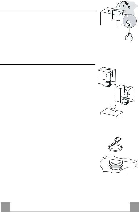
Hood body assembly
•Adjust the two screws Vr of brackets 11a, by just placing them in position.
•Hook the hood body to the two brackets 11a.
•Pull the Comfort Panel to open it, remove the filters one by one, push them towards the rear part of the unit and pull downwards at the same time .
•From inside the hood body, tighten the screws Vr to level the body.
Connection
AIR OUTLET IN A DUCTING HOOD VERSION
When installing the hood in ducting version, basing on the installer’s choice, a rigid or a flexible pipe with a ø 150 or 120 mm is used in order to connect the hood to the air outlet piping. The pipe connection can be made on the upper part or on the rear side of the hood.
Before connecting the hood to the air outlet ducting remove the lateral air outlet grid 8 and the plastic tube 7. The adapting flange 9 has to be removed only in case the connecting diameter is 150.
REAR AIR OUTLET
•When drilling the air outlet hole in the wall proceed in accordance with the scheme in the part concerning the wall drilling.
•Use a pair of tongs when breaking the rear air outlet hole in the wall.
•In case the connection is made by using a ø 120 mm pipe insert the reduction flange 9 on the hood body outlet.
•Fix the pipe with an adequate quantity of pipe clamps. This material is not supplied together with the hood.
•Remove the charcoal filter if present.
•Fix the metal cover 10 to the upper air outlet hole of the hood by using the screws supplied.
UPPER AIR OUTLET
•In case the connection is made by using a ø 120 mm pipe insert the reduction flange 9 on the hood body outlet.
•Use a pair of tongs when removing the central part of the metal cover 10. Fix the cover to the air outlet hole of the hood by using the screws supplied.
•Fix the pipe with an adequate quantity of pipe clamps. This material is not supplied together with the hood.
•Remove the charcoal filter if present.
EN
11a |
Vr |
ø 150 |
9 |
ø 120 |
10 |
10 |
6 |
6 |
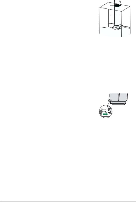
AIR OUTLET IN A RECYCLING HOOD VERSION
•In case the components requested for the recycling functioning have been removed earlier these have to be positioned again.
•Put the plastic tube onto the flange 7.
•Place the air outlet grid 8 on the air outlet. Make sure that the position of the grid is correct.
•Make sure that charcoal filters have been placed inside the hood.
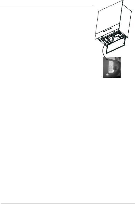
ELECTRICAL CONNECTION
•Connect the hood to the mains through a two-pole switch having a contact gap of at least 3 mm.
•Remove the grease filters (see paragraph Maintenance) being sure that the connector of the feeding cable is correctly inserted in the socket placed on the side of the fan.
8
7
EN |
|
7 |
|
7 |
USE
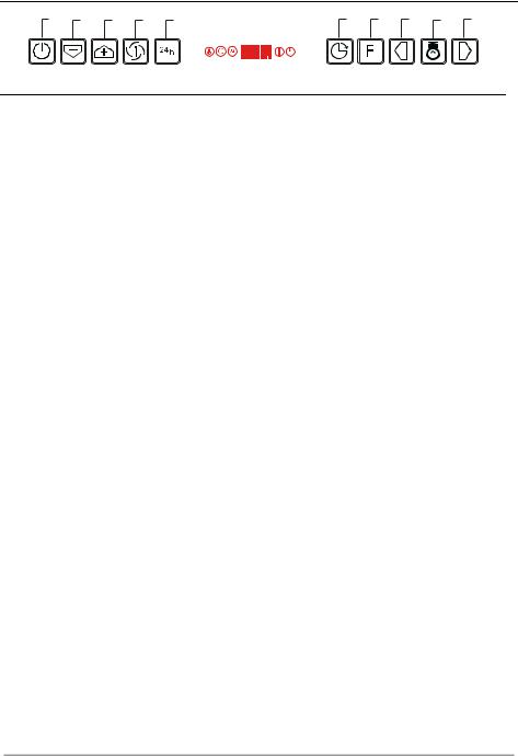
A B C D E F G H I L
Control panel
|
Button |
Function |
Display |
|
A |
Carriage Closed: If the button is pressed and held for at |
Displays the set speed, 2 LED indicators per speed. |
|
|
least 1.5 seconds, the Carriage opens, the Motor starts |
|
|
|
at speed 2 and the Lights turn on at maximum intensity. |
|
|
|
Carriage Open: If the button is pressed briefly the |
|
|
|
Motor turns on/off. If the button is pressed and held for |
N.B. If the Carriage blocks while closing due to |
|
|
at least 1.5 seconds, the Carriage closes and the Motor |
obstacles or the like, it will block for 1 second and will |
|
|
switches off. |
then open again. |
|
|
|
|
|
B |
Decreases the working speed. |
The number of lighted segments decreases. |
|
|
Only active with the Carriage open. |
|
|
C |
Increases the working speed. |
The number of lighted segments increases. |
|
|
Only active with the Carriage open. |
|
|
D |
Activates Intensive speed from any other speed, with |
The indicator I flashes and all the segments on the |
|
|
the exception of Delay. This speed is set to operate for |
Display are lit. |
|
|
10 minutes, after which the system returns to the speed |
It is disabled by pressing the Button. |
|
|
that was set before. Suitable to deal with maximum |
|
|
|
levels of cooking fumes. |
|
|
E |
Can only be activated if Intensive and Delay are Off. |
Displays 24 and the segments on the Display all light |
|
|
Starts the Motor at a speed that allows suction of 100 |
up and then turn off one at a time in cycle. |
|
|
m3/h for 10 minutes per hour, after which the Motor |
|
|
|
will stop (24H function). |
It is disabled by pressing the Button or the Motor |
|
|
Carriage Closed: If the button is pressed briefly the |
On/Off button (button A). |
|
|
function is activated. |
|
|
|
With the function active, if the Motor On/Off button is |
|
|
|
pressed and held for at least 1.5 seconds, the function is |
|
|
|
disabled, the Carriage opens, the Motor starts at speed 2 |
|
|
|
and the Lights turn on at maximum intensity. |
|
|
|
Carriage Open: If the button is pressed briefly the |
|
|
|
Motor switches off, the Carriage closes and the |
|
|
|
function is activated. |
|
|
F |
Can only be activated if Intensive or 24H are Off. |
Displays a flashing Clock symbol. |
|
|
Activates automatic switch-off with a 30’ delay. |
It is disabled by pressing the button or turning the |
|
|
Suitable to complete elimination of residual odours. |
motor off. |
|
G |
Performs a Reset of the Filter saturation alarm when |
After 100 hours in operation the Drop symbol is |
|
|
the Button is pressed for approximately 2 seconds with |
displayed to indicate saturation of the Metal Grease |
|
|
Motor and Lights Off. |
Filters. |
|
|
|
After 200 hours in operation the letter C is displayed to |
|
|
|
indicate saturation of the Activated Charcoal filters. |
|
H |
Decreases the intensity of the Lighting each time the |
|
|
|
Button is pressed, in cycle. |
|
|
I |
Turns the lighting system on and off at maximum |
|
|
|
intensity. |
|
|
L |
Increases the intensity of the Lighting each time the |
|
|
|
Button is pressed, in cycle. |
|
Keyboard Lock: it is possible to lock the keyboard, for example when cleaning the Glass surface, when the Hood has Motor and Lights turned off.
Press D (Intensive) for approximately 5 Seconds to enable or disable the Keyboard Lock, which is always confirmed by a Beep and an animation on the display Motor bar.
EN |
|
8 |
|
8 |
MAINTENANCE
REMOTE CONTROL (OPTIONAL)
The appliance can be controlled using a remote control powered by a 1.5 V carbon-zinc alkaline batteries of the standard LR03AAA type.
• Do not place the remote control near to heat sources.
• Used batteries must be disposed of in the proper manner.
Cleaning the Comfort Panels
• Pull the Comfort Panel to open it.
• Disconnect the panel from the hood canopy by sliding the fix-
ing pin lever.
• The comfort panel must never be washed in a dishwasher.
• Clean the outside using a damp cloth and neutral liquid deter-
gent.
• Clean the inside as well using a damp cloth and neutral detergent; do not use wet cloths or sponges, or jets of water; do not use abrasive substances.
•When the above operation has been completed, hook the panel back to the hood canopy and close it by turning the knob in the opposite direction.
EN |
|
9 |
|
9 |

Metal grease filters
These can be washed in the dishwasher, and need to be cleaned whenever the Drop symbol appears on the display or at least once every 2 months use, or more frequently if use is particularly intensive.
Resetting the alarm signal
• Press button G and hold it for at least 2 seconds.
Cleaning the Filters
•If closed, open the Carriage by pressing button A and holding for at least 1.5 seconds (see USE).
•Open the comfort panel.
•Remove the Filters one at a time, pushing them towards the back of the unit and at the same time pulling downward.
•Wash the Filters without bending them, and leave them to dry completely before replacing. (If the surface of the filter changes colour as time goes by, this will have absolutely no effect on the efficiency of the filter itself.)
•Replace, taking care to ensure that the handle faces forwards.
•Close the comfort panel.
EN |
|
1 |
|
10 |
Charcoal filter (recycling version)
This filter cannot be washed or regenerated. It must be replaced when the C appears on the display or at least once every 4 months. The filter saturation alarm has to be activated already before.
Activation of the alarm signal
•In the recycling version hoods the filter saturation alarm must be activated during the installation or later.
•Switch off the hood and the lights.
•Press the E-key for about 5 seconds until the last two segments of the motor LEDS are lit on the display.
•By releasing the E-key the clock icon starts to flash.
•Within 3 seconds press the D-key to activate/deactivate charcoal filter saturation alarm.
•C-symbol lit - charcoal filter saturation alarm ACTIVATED.
•C-symbol unlit - charcoal filter saturation alarm DEACTIVATED.
CHANGING THE ACTIVATED CHARCOAL FILTER |
|
|
Resetting the alarm signal |
|
|
• Press button G and hold it for at least 2 seconds. |
|
|
Changing the Filter |
|
|
• If closed, open the Carriage by pressing button A and holding |
B |
A |
for at least 1.5 seconds (see USE). |
||
• Open the comfort panel. |
|
|
• Remove the grease filters. |
|
|
• Remove the saturated Activated Charcoal Filters, as indicated |
|
|
(A). |
|
|
• Fit the new Filters, as indicated (B). |
|
|
• Replace the metal grease filters. |
|
|
• Close the comfort panel. |
|
|
Lighting
LIGHT REPLACEMENT
20 W halogen light.
•Extract the lamp from the lamp holder by pulling gently.
•Replace with another of the same type, making sure that the two pins are properly inserted in the lamp holder socket holes.
EN
1
11
Replacing the fuser
•Open the comfort panel.
•Remove the grease filters.
•The fuser is placed up on the right side. Turn the fuser holder as indicated. Replace the fuser with one having the same features.
•Put the fuser holder and grease filters into their place again. Make sure that the hood functions correctly. In case the panel
doesn’t work correctly it is necessary to contact an authorized technician.
EN |
|
1 |
|
12 |
CONSIGLI E SUGGERIMENTI
 Questo libretto di istruzioni per l'uso è previsto per più versioni dell' apparecchio. É possibile che siano descritti singoli particolari della dotazione, che non riguardano il Vostro apparecchio.
INSTALLAZIONE
•Il produttore declina qualsiasi responsabilità per danni dovuti ad installazione non corretta o non conforme alle regole dell’arte.
•La distanza minima di sicurezza tra il Piano di cottura e la Cappa deve essere di 650 mm, (alcuni modelli possono essere installati ad un’altezza inferiore, fare riferimento ai paragrafi ingombro e installazione).
•Verificare che la tensione di rete corrisponda a quella riportata nella targhetta posta all’interno della Cappa.
•Per Apparecchi in Classe Ia accertarsi che l’impianto elettrico domestico garantisca un corretto scarico a terra.
•Collegare la Cappa all’uscita dell’aria aspirata con tubazione di diametro pari o superiore a 120 mm. Il percorso della tubazione deve essere il più breve possibile.
•Non collegare la Cappa a condotti di scarico dei fumi prodotti da combustione (caldaie, caminetti, ecc.).
•Nel caso in cui nella stanza vengano utilizzati sia la Cappa che apparecchi non azionati da energia elettrica (ad esempio apparecchi utilizzatori di gas), si deve provvedere ad una aerazione sufficiente dell’ambiente. Se la cucina ne fosse sprovvista, praticare un’apertura che comunichi con l’esterno, per garantire il richiamo d’aria pulita.
USO
•La Cappa è stata progettata esclusivamente per uso domestico, per abbattere gli odori della cucina.
•Non fare mai uso improprio della Cappa.
•Non lasciare fiamme libere a forte intensità sotto la Cappa in funzione.
•Regolare sempre le fiamme in modo da evitare una evidente fuoriuscita laterale delle stesse rispetto al fondo delle pentole.
•Controllare le friggitrici durante l’uso: l’olio surriscaldato potrebbe infiammarsi.
•Non preparare alimenti flambè sotto la cappa da cucina; pericolo d'incendio.
•Questo apparecchio non deve essere utilizzato da persone (bambini inclusi) con ridotte capacità psichiche, sensoriali o mentali, oppure da persone senza esperienza e conoscenza, a meno che non siano controllati o istruiti all’uso dell’apparecchio da persone responsabili della loro sicurezza.
•I bambini devono essere supervisionati per assicurarsi che non giochino con l’apparecchio.
MANUTENZIONE
•Prima di procedere a qualsiasi operazione di manutenzione, disinserire la Cappa togliendo la spina elettrica o spegnendo l’interruttore generale.
•Effettuare una scrupolosa e tempestiva manutenzione dei Filtri secondo gli intervalli consigliati (Rischio di incendio).
•Per la pulizia delle superfici della Cappa è sufficiente utilizzare un panno umido e detersivo liquido neutro.
Il simbolo  sul prodotto o sulla confezione indica che il prodotto non deve essere considerato come un normale rifiuto domestico, ma deve essere portato nel punto di raccolta appropriato per il riciclaggio di apparecchiature elettriche ed elettroniche. Provvedendo a smaltire questo prodotto in modo appropriato, si contribuisce a evitare potenziali conseguenze negative per l’ambiente e per la salute, che potrebbero derivare da uno smaltimento inadeguato del prodotto. Per informazioni più dettagliate sul riciclaggio di questo prodotto, contattare l’ufficio comunale, il servizio locale di smaltimento rifiuti o il negozio in cui è stato acquistato il prodotto.
IT
1
13
CARATTERISTICHE
Ingombro
Min. |
Min. |
650mm 650mm |
|
Componenti
Rif. Q.tà Componenti di Prodotto
11 Corpo Cappa completo di: Comandi, Luce, Gruppo Ventilatore, Filtri, Camino Inferiore
7 |
1 |
Tubo PVC (Installato) |
8 |
1 |
Griglia direzionata (Installata) |
9 |
1 |
Flangia di Riduzione ø 150-120 mm |
10 |
1 |
Tappo |
|
|
|
Rif. |
Q.tà |
Componenti di Installazione |
11a |
2 |
Tasselli SB 12/10 |
|
|
|
|
Q.tà |
Documentazione |
|
1 |
Libretto Istruzioni |
10 |
9 |
11a
8
7
IT |
|
1 |
|
14 |
INSTALLAZIONE
Foratura Parete
Qualora si voglia collegare la cappa in versione aspirante, facendo uscire il tubo sulla parte posteriore, si ricorda che il foro di evacuazione dell’aria deve essere fatto seguendo le indicazione di seguito riportate nel disegno.
|
230 |
230 |
11a |
275 |
|
|
|
|
|
|
250 |
|
|
658 |
|
442 |
|
|
650 mm min |
|
Zona uscita aria posteriore
Nel caso di installazione della cappa in versione filtrante, tenere in considerazione che, sopra la cappa, deve rimanere una distanza dal limite superiore (Soffitto o Mensola) di almeno 8-10 Cm.
Tracciare sulla Parete:
•una linea Verticale fino al soffitto o al limite superiore, al centro della zona prevista per il montaggio della Cappa;
•una linea Orizzontale a: 650 mm min. sopra il Piano di Cottura;
•Segnare come indicato, un punto di riferimento a 658 mm sopra la linea orizzontale di riferimento, e a 230 sulla destra della linea verticale di riferimento.
•Ripetere questa operazione dalla parte opposta, verificandone il livellamento.
•Forare ø 12 mm i punti segnati.
•Inserire i tasselli con vite e staffa 11a nei fori, avvitare.
IT |
|
1 |
|
15 |
Montaggio Corpo Cappa
•Regolare le due viti Vr, delle staffe 11a, ad inizio corsa.
•Agganciare il corpo cappa alle 2 staffe 11a.
•Aprire il Comfort Panel tirandolo, togliere i Filtri uno alla volta, spingendoli verso la parte posteriore del gruppo e tirando contemporaneamente verso il basso.
•Dall’interno del corpo cappa agire sulle Viti Vr per livellare il Corpo Cappa.
Connessioni
USCITA ARIA VERSIONE ASPIRANTE
Per installazione in Versione Aspirante collegare la Cappa alla tubazione di uscita per mezzo di un tubo rigido o flessibile di ø 150 o 120 mm, la cui scelta è lasciata all'installatore. Il tubo può uscire sia dalla parte superiore che posteriore della cappa.
Prima di procedere alle connessioni aspiranti rimuovere, qualora non sia già stato fatto, la griglia direzionata 8 e il tubo in pvc 7. La flangia di riduzione 9 va rimossa solo per effettuare collegamenti da ø 150.
USCITA POSTERIORE
•Si ricorda che per effettuare il foro di evacuazione va seguito lo schema riportato nel paragrafo foratura parete.
•Rompere il foro di uscita posteriore con l’ausilio di una pinza.
•Per collegamento con tubo ø120 mm, inserire la Flangia di riduzione 9 sull'Uscita del Corpo Cappa.
•Fissare il tubo con adeguate fascette stringitubo. Il materiale occorrente non è in dotazione.
•Togliere eventuali Filtri Antiodore al Carbone attivo.
•Fissare il Tappo 10 sull’Uscita Superiore della Cappa con le Viti in dotazione.
USCITA SUPERIORE
•Per collegamento con tubo ø120 mm, inserire la Flangia di riduzione 9 sull'Uscita del Corpo Cappa.
•Rimuovere la parte centrale del Tappo 10 con l’ausilio di una pinza e fissarlo sull’Uscita Superiore della Cappa con le Viti in dotazione.
•Fissare il tubo con adeguate fascette stringitubo. Il materiale occorrente non è in dotazione.
•Togliere eventuali Filtri Antiodore al Carbone attivo.
IT
11a |
Vr |
ø 150 |
9 |
ø 120 |
10 |
10 |
1 |
16 |

USCITA ARIA VERSIONE FILTRANTE
•Qualora fossero stati rimossi riposizionare i componenti per versione filtrante già installati.
•Inserire il tubo in pvc 7 sulla Flangia.
•Riavvitare la Griglia direzionata 8 sull’uscita dell’aria, facendo attenzione che sia posizionata correttamente sul tubo.
•Assicurarsi della presenza dei Filtri antiodore al Carbone attivo.
CONNESSIONE ELETTRICA
•Collegare la Cappa all’Alimentazione di Rete interponendo un Interruttore bipolare con apertura dei contatti di almeno 3 mm.
•Rimuovere i Filtri antigrasso (vedi par. “Manutenzione”) e assicurarsi che il connettore del Cavo di alimentazione sia correttamente inserito nella presa dell’Aspiratore
8
7
IT |
|
1 |
|
17 |
 Loading...