

Page 1
USER MANUAL
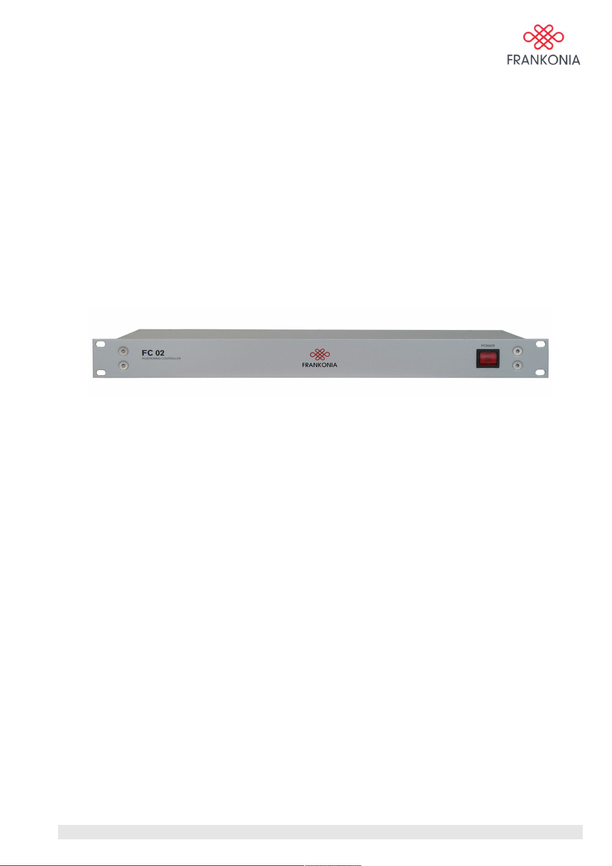
FC 02
Controller for turntable and antenna mast
MA_FC02_(Rev2_1) - 9/06 / Version 1 / Rev:2.1
1 / 24
Page 2

Contents
1.0 Safety Summary....................................................................................................................................... 3
2.0 Introduction..............................................................................................................................................4
3.0 General description.................................................................................................................................. 5
Front Panel Features............................................................................................................................. 5
Rear Panel Features ............................................................................................................................. 5
4.0 Configuration........................................................................................................................................... 7
Optic connections to devices................................................................................................................ 7
Connections to computer......................................................................................................................7
5.0 Software installation................................................................................................................................ 9
Hardware- and Software Requirements................................................................................................9
Installation of FC 02 application software............................................................................................9
6.0 Software operation................................................................................................................................. 10
Overview............................................................................................................................................ 10
Turntable controls...............................................................................................................................11
Antenna mast controls........................................................................................................................ 13
Program functions...............................................................................................................................15
7.0 IEEE 488.2 commands...........................................................................................................................17
Commands..........................................................................................................................................17
8.0 SCPI commands.....................................................................................................................................18
IEEE 488.2 Status Registers...............................................................................................................21
SCPI Error Code.................................................................................................................................22
9.0 Specifications.........................................................................................................................................23
MA_FC02_(Rev2_1) - 9/06 / Version 1 / Rev:2.1
2 / 24
Page 3

1.0 Safety Summary
The following general safety precautions must be observed during all phases of operation, service, and
repair of this instrument. Failure to comply with these precautions or with specific warnings elsewhere in
this manual violates safety standards of design, manufacture, and intended use of this instrument.
We assume no liability for the customer´s failure to comply with these requirements.
Before applying power:
• Verify that the product is set to match the available line voltage and that the correct fuse is
installed.
Ground the instrument:
• This product is a Safety Class 1 Product (provided with a protective earthing ground
incorporated in the power cord). The mains plug shall only be inserted in a socket outlet
provided with a protective earth contact. Any interruption of the protective conductor
inside or outside of the product is likely to make the product dangerous. Intentional
interruption is prohibited.
Do not remove instrument covers:
• Operating personnel must not remove instrument covers. There are no user serviceable
parts inside. Refer servicing to qualified personnel.
MA_FC02_(Rev2_1) - 9/06 / Version 1 / Rev:2.1
3 / 24
Page 4

2.0 Introduction
The FC 02 is a positioning controller developed for using the different positioning devices developed by
Frankonia.
This controller allows any user to control in the meantime several devices as turntables, antenna mast,
slide clamp bar, etc …
The FC 02 offers different ways of control by providing serial RS-232 as well as GPIB (IEEE488.2)
interfaces.
The connection to the different devices is made using optic fibers duplex cables in order to avoid any RF
interferences, which could be conducted along wire cables.
Complete software with an attractive and ergonomic design is delivered with each controller in order to
control the devices manually and also to have a display of the operations in real time.
MA_FC02_(Rev2_1) - 9/06 / Version 1 / Rev:2.1
4 / 24
Page 5
3.0 General description
The FC 02 is delivered in a 1U – 19” rack size in order to win a lot of space into the system units rack.
Also the depth is half size and doesn’t need any additional fixation kit.
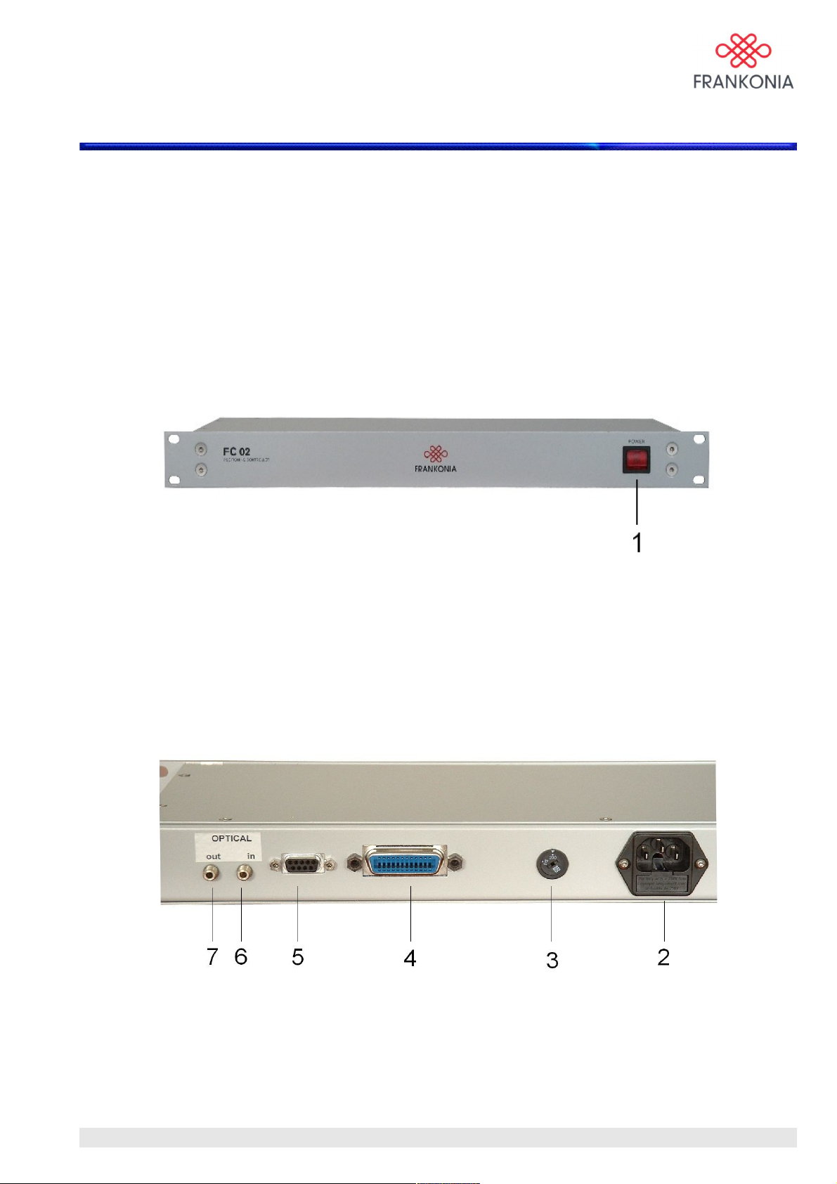
Only a power switch with light is available on the front.
At the rear all the communication ports and optic connections are installed.
The FC 02 integrates a flash memory. The firmware could be easily upgraded via the RS232 port linked to
a PC. The firmware upgrade will be available on our website in the download section as well as a detailed
description of this procedure. This offers also the possibility to modify easily our positioning controller in
order to solve some communication problems with some testing software.
Front Panel Features
[1]: Power
Line switch turns the FC 02 on and off
Rear Panel Features
The FC 02 uses only 2 optic fibers channel for controlling up to 16 different devices.
The basic version of this controller is able to control one turntable and two antenna masts.
[2]: Power input
Input for the line power source.
Line Fuse: Replace only with a fuse of the same rating. See the label on the rear panel.
[3]: Voltage selector - verify that the product is set to match the available line voltage
MA_FC02_(Rev2_1) - 9/06 / Version 1 / Rev:2.1
5 / 24
Page 6

[4]: IEEE-488 (GPIB)
24 pin Centronics connector. The GPIB interface Bus complies with the IEEE 488.2
standards. The FC 02 use the Standard Commands for Programmable Instruments (SCPI) and
the IEEE 488.2 protocol on which SCPI is based.
[5]: Serial connector (RS-232)
The RS 232 port is a standard serial port (Baud rate 9600) used for the manual mode or used
for upgrading the flash memory. The socket is a type Sub 9 pin female.
[6]: Optical in
F-SMA Receiver, 660nm
[7]: Optical out
F-SMA Transmitter, 660nm
MA_FC02_(Rev2_1) - 9/06 / Version 1 / Rev:2.1
6 / 24
Page 7
4.0 Configuration
Optic connections to devices
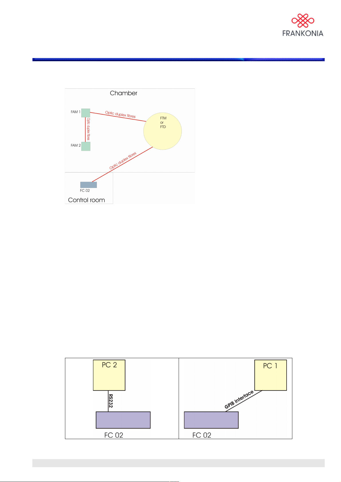
FTM / FTD = Frankonia TurnTable
FAM = Frankonia Antenna Mast
As you can see in order to simplify the fibers optic layout Frankonia had developed an optic bus system in
the chamber. Up to 16 different Frankonia devices can be connected to this bus using the same controller
hardware. The software must be developed according to the different devices.
Only one duplex fiber starts from the FC 02.
Connections to computer
Several possibilities are offered for connecting the FC 02 to the Computer in charge of the
instrumentation control.
The FC 02 can be used in manual mode using the RS232 or the GPIB interface using a computer
connected to one of these 2 interfaces.
The software delivered with the controller will be able to control by a few clicks with your mouse the
whole system, and you will visualize the operation in real time on your computer screen display.
Manual Mode and automatic mode without instrumentation
MA_FC02_(Rev2_1) - 9/06 / Version 1 / Rev:2.1
7 / 24
Page 8
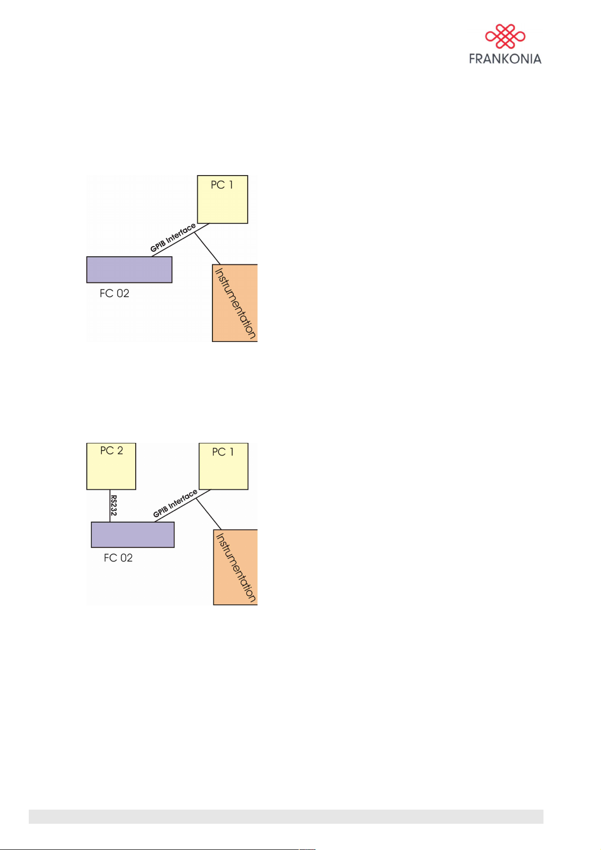
The FC 02 can be connected in parallel into the GPIB chain and can receive orders as the whole
instrumentation in automatic mode. Our software will display the operation in course in the meantime
(several windows could be open on the computer PC1).
Also orders can be given manually to the FC 02 using our software.
Automatic mode with instrumentation
The FC 02 could be connected also to 2 separate computers if needed.
This offers the possibility to get the display on a separate computer using the RS232 port if needed.
Automatic mode with 2 computers
MA_FC02_(Rev2_1) - 9/06 / Version 1 / Rev:2.1
8 / 24
Page 9

5.0 Software installation
• If you send directly SCPI commands on the GPIB interface,
you don’t need any driver or software.
• If you want a visualization of the operation in course or control manually the devices,
then you need to install the software delivered with the controller.
Hardware- and Software Requirements
You should have the following hardware and software to work with your FC 02:
• PC with Windows NT/2000/XP operating system
• compatible mouse and VGA graphics (min. 800 x 600 pts.).
Installation of FC 02 application software
• Insert the application software CD and click on setup.exe
• Follow the instructions on your screen.
• The installer creates a directory named FC02 where you can doubleclick on FC02.exe to
start the application.
MA_FC02_(Rev2_1) - 9/06 / Version 1 / Rev:2.1
9 / 24
Page 10
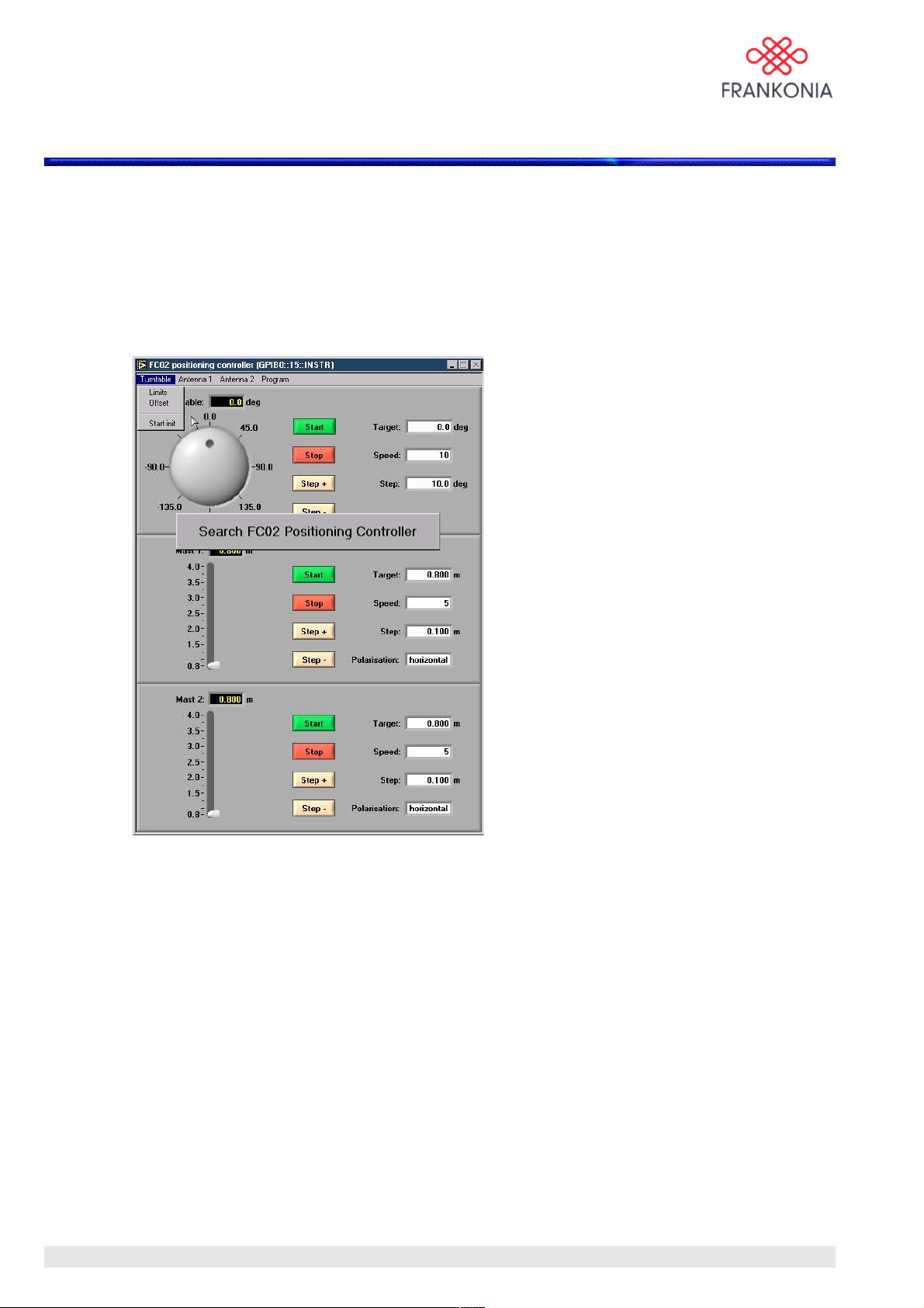
6.0 Software operation
Overview
After installation of the software and configuration of the hardware devices you are ready to
➔ Double-click on FC02.exe (Directory FC02/FC02.exe)
The following main menu is displayed:
The FC 02 software checks automatically the status of the network connected on the optic fiber link, and
shows 2 main parts in its standard version.
The upper part concerns the FTM (Frankonia Turntable), and the lower part concerns the FAM
(Frankonia antenna mast).
When a device is not found, the software indicates it, and the corresponding part is shown in grey.
When you power on the system, it needs to be initialized in order to find its reference point.
The initialisation procedure is performed automatically and described in the FTM and FAM user manuals.
The software indicates automatically if turntable and/or antenna mast have to be initialized.
How to start the initialisation run for turntable and antenna mast is described later in this manual.
MA_FC02_(Rev2_1) - 9/06 / Version 1 / Rev:2.1
10 / 24
Page 11
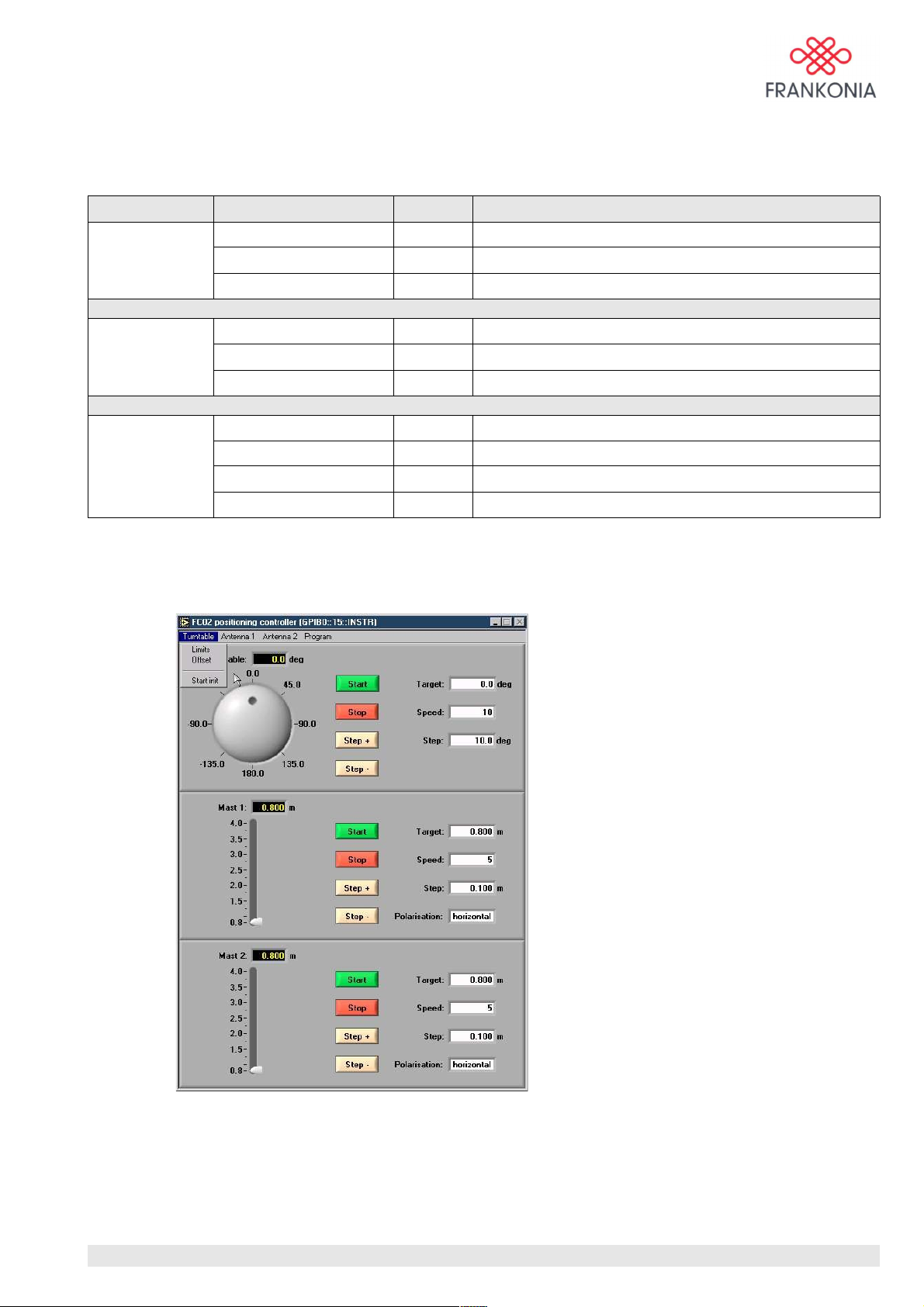
Only when the init is made, all the commands will be available.The menu bar contains the main
commands. The following table explains each menu item on the menu bar in order from left to right:
Menu Item Shortcut Function
Turntable Limits Enter limits of movement of the turntable in degrees
Offset Enter offset of movement of the turntable in degrees
Start init Start an initialisation run of the turntable
Antenna Limits Enter limits of movement of antenna mast in m
Offset Enter offset of movement of antenna mast in m
Start init Start an initialisation run of the antenna mast
Program Load settings Strg+L Load settings
Save settings Strg+S Save current settings
Info Show program version
Quit Strg+Q Exit the application software
Turntable controls
The software limits of the turntable can be lowered if needed. As a factory setting theses values are set to
max. –200° and + 200°. We have defined this value in order to avoid any problems with the cables of the
equipment under test if the turntable makes a complete tour on itself.
MA_FC02_(Rev2_1) - 9/06 / Version 1 / Rev:2.1
11 / 24
Page 12
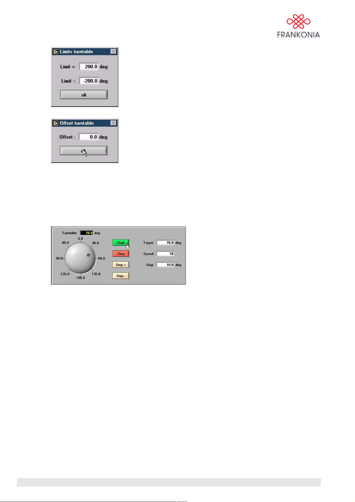
An offset is available in order to offer the possibility to modify the init position if necessary. As a
standard this value is set to 0. This value must be entered in degrees.
When the turntable had finished the initialization, the reference starting point is 0,0°.
➔ Click on Turntable/start init to start the initialisation run of the turntable
The accuracy of our turntables is +/- 0,2°. Our controller FC 02 is a high resolution, and it can control the
turntables with a resolution of 0,1°.
Our turntable presents 30 levels of speed (more details are available in the FTT user manual).
With our software, you can set what you want into the right white cases:
• Target: from –200° to 200° (depending on the settings for offset & limits)
• Step: from 0 ° to 200°
• Speed: from 1 (slow) to 30 (fast)
• Please notice: The rotating knob represents the physical position of the turntable and is not
influenced by the settings of limits and offset!
The displayed values (deg) take into account the setting of offset!
• If the software detects a motion initiated by an external software all buttons except the Stop
button are disabled. All buttons are enabled again 20 sec after the motion stops.
Target is the angle where you want to go. When you click on start the turntable will move to this place at
the speed choosen.
Step is a step of angle which will be reproduced each time you click on Step + or Step – at the speed
choosen.
Before the use of high speed, be sure that the equipment under test is fixed correctly.
MA_FC02_(Rev2_1) - 9/06 / Version 1 / Rev:2.1
12 / 24
Page 13
When the software limit is or will be reached within the next moving the turntable will refuse to start. In
that case you must reduce your requirement, or go in the other direction.
If you use automatic commands via GPIB interface, this software will serve you also as a display.
Antenna mast controls
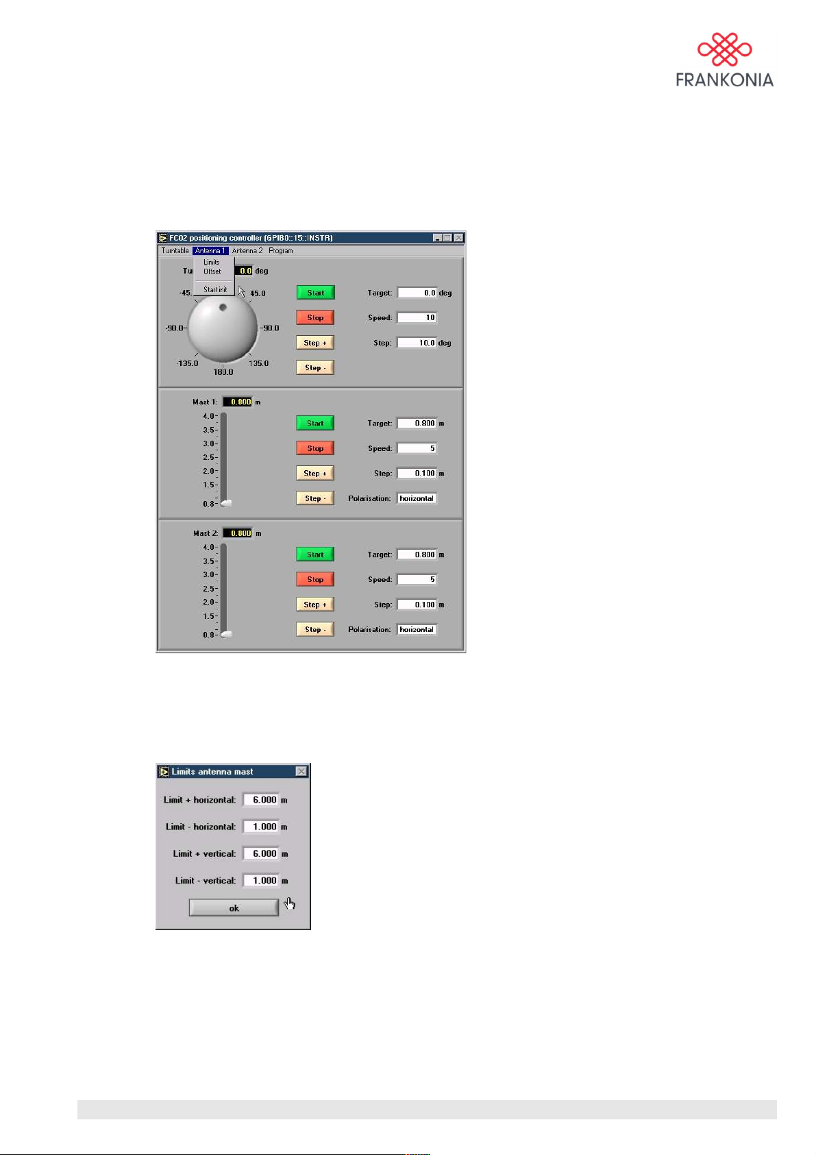
The software limits of the antenna mast can be changed if needed. As a factory setting these values are set
to 0,8m and 4m (in case of 4m antenna mast) or 6m (in case of 6m antenna mast).
We have defined these values in order to avoid any problem with standard use of antennas.
An offset is available in order to offer the possibility to modify the init position if necessary, or to avoid
any trouble with antennas with different sizes. As a standard this value is set to 0. This value must be
entered in m.
MA_FC02_(Rev2_1) - 9/06 / Version 1 / Rev:2.1
13 / 24
Page 14
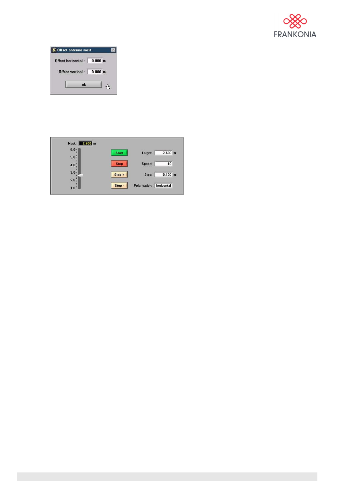
When the antenna mast has finished the initialization, the reference starting point is 0,8m in standard.
This offset can be set for horizontal and for vertical polarizations.
➔ click on Antenna/start init to start the initialisation run of the antenna mast
The accuracy of our antenna mast is +/- 3mm. Our controller FC 02 is a high resolution, and can control
the antenna mast with a unit of 1mm.
Our antenna mast presents 30 levels of speed (more details are available into the FAM user manual).
With our software, you can set what you want into the right white cases:
• Target: from 0,8m to 4m or 6m (depending on the settings for offset & limits)
• Step: from 0m to 3,2 m or 5,2m
• Speed: from 1 (slow) to 30 (fast)
• Please notice: The up and down going knob represents the physical position of the antenna
and is not influenced by the settings of limits and offset!
The displayed values (m) take into account the setting of offset!
• If the software detects a motion initiated by an external software all buttons except the Stop
button are disabled. All buttons are enabled again 20 sec after the motion stops.
Target is the position where you want to go. When you click on start the antenna mast will move to this
place at the speed choosen.
Step is a step of distance which will be reproduced each time you click on Step + or Step – at the speed
choosen.
Before the use of high speed, be sure that the antenna is fixed correctly, and that there is no
obstruction for the coaxial cables.
When the software limit is or will be reached within the next moving the antenna mast will refuse to start.
In that case you must reduce your requirement, or go in the other direction.
If you use automatic commands via GPIB interface, this software will serve you also as a display.
MA_FC02_(Rev2_1) - 9/06 / Version 1 / Rev:2.1
14 / 24
Page 15
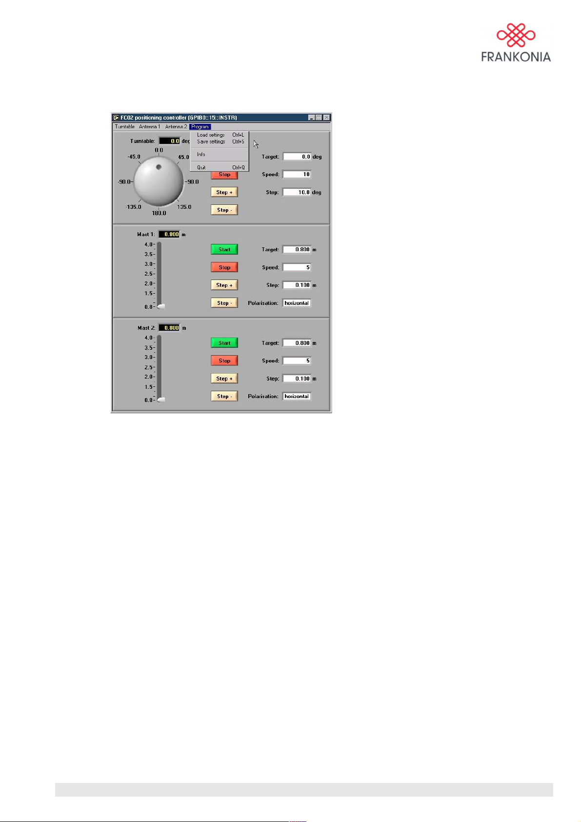
Program functions
Each time you start the software, the file default.set is loaded. The default settings of this file are
explained in the table below:
MA_FC02_(Rev2_1) - 9/06 / Version 1 / Rev:2.1
15 / 24
Page 16

Variable Default setting Description
offset 0,0 deg Turntable offset
limit_max 200,0 deg Turntable limit +
limit_min -200,0 deg Turntable limit -
speed_ttab 10 Turntable speed
step_ttab 10 deg Turntable step
offset_h 0,000 m Antenna mast horizontal offset
offset_v 0,000 m Antenna mast vertical offset
limit_h_max 4,000 m Antenna mast hor. limit +
limit_h_min 0,800 m Antenna mast hor. limit -
limit_v_max 4,000 m Antenna mast vert. limit +
limit_v_min 0,800 m Antenna mast vert. limit -
speed_ant 10 Antenna mast speed
step_ant 0,100 m Antenna mast step
heigh 4,000 m Antenna mast height
init 0,800 m Initialisation point
offset_h2 0,000 m Antenna mast 2 horizontal offset
offset_v2 0,000 m Antenna mast 2 vertical offset
limit_h_max2 4,000 m Antenna mast 2 hor. limit +
limit_h_min2 0,800 m Antenna mast 2 hor. limit -
limit_v_max2 4,000 m Antenna mast 2 vert. limit +
limit_v_min2 0,800 m Antenna mast 2 vert. limit -
speed_ant2 5 Antenna mast 2 speed
step_ant2 0,100 m Antenna mast 2 step
height2 4,000 m Antenna mast 2 height
init2 0,800 m Initialisation point antenna mast 2
Variables of default.set
➔ Click on Program/Load settings to load a predefined setup file.
➔ Click on Program/Save settings to overwrite the default settings or to create as many
different setup files as you want.
➔ Click on Program/Info to show the version number of the software.
➔ Click on Program/Quit to exit the application software.
MA_FC02_(Rev2_1) - 9/06 / Version 1 / Rev:2.1
16 / 24
Page 17

7.0 IEEE 488.2 commands
Commands
• *CAL: Conducts a calibration (initialization run) if the device is not calibrated. During initialization
run, the logical device cannot be changed!
• *CAL?: Query of calibration status of the selected logical device.
Answers: 0: calibration successful
1: calibration failed
2: calibration in course
• *CLS: Clear Status sets the status registers ESR, STB, OPER and QUEST at zero.
• *ESE <0...255>: Event Status Enable sets the event status enable register with the selected value.
• *ESE?: Query of the event status enable register.
• *ESR?: Query and deletion of the event status register.
• *IDN?: Query of the identification text (Frankonia, FC02, 0, V1.0).
• *OPC: Operation Complete sets the OPC bit (bit 0) in the event status register, after completed
execution of all previous commands.
• *OPC?: Query Operation Complete reports an additional 1, after completed execution of all previous
commands.
• *RST: Sets the equipment to initial state.
Limit:high = maximum, Limit:low = minimum, Offset = 0, Direction = up, Step = 0.1m (antenna +
clamp) / = 10° (turntable), velocity = 10
• *SRE <0...255>: Service Request Enable sets the service request enable register with the selected
value.
• *SRE?: Query of the service request enable register.
• *STB?: Query of the status register (serial poll)
• *TST?: Equipment performs self test and reports 0 (no failure) or 1 (failure).
• *WAI: Wait to Continue allows the execution of a new command only after completed execution of all
previous commands.
When the controller is switched on, all status and enable registers are set to 0 and all parameters are set to
initial state (Exception: Bit 7 of the event status register is set to „Power on“.)
MA_FC02_(Rev2_1) - 9/06 / Version 1 / Rev:2.1
17 / 24
Page 18
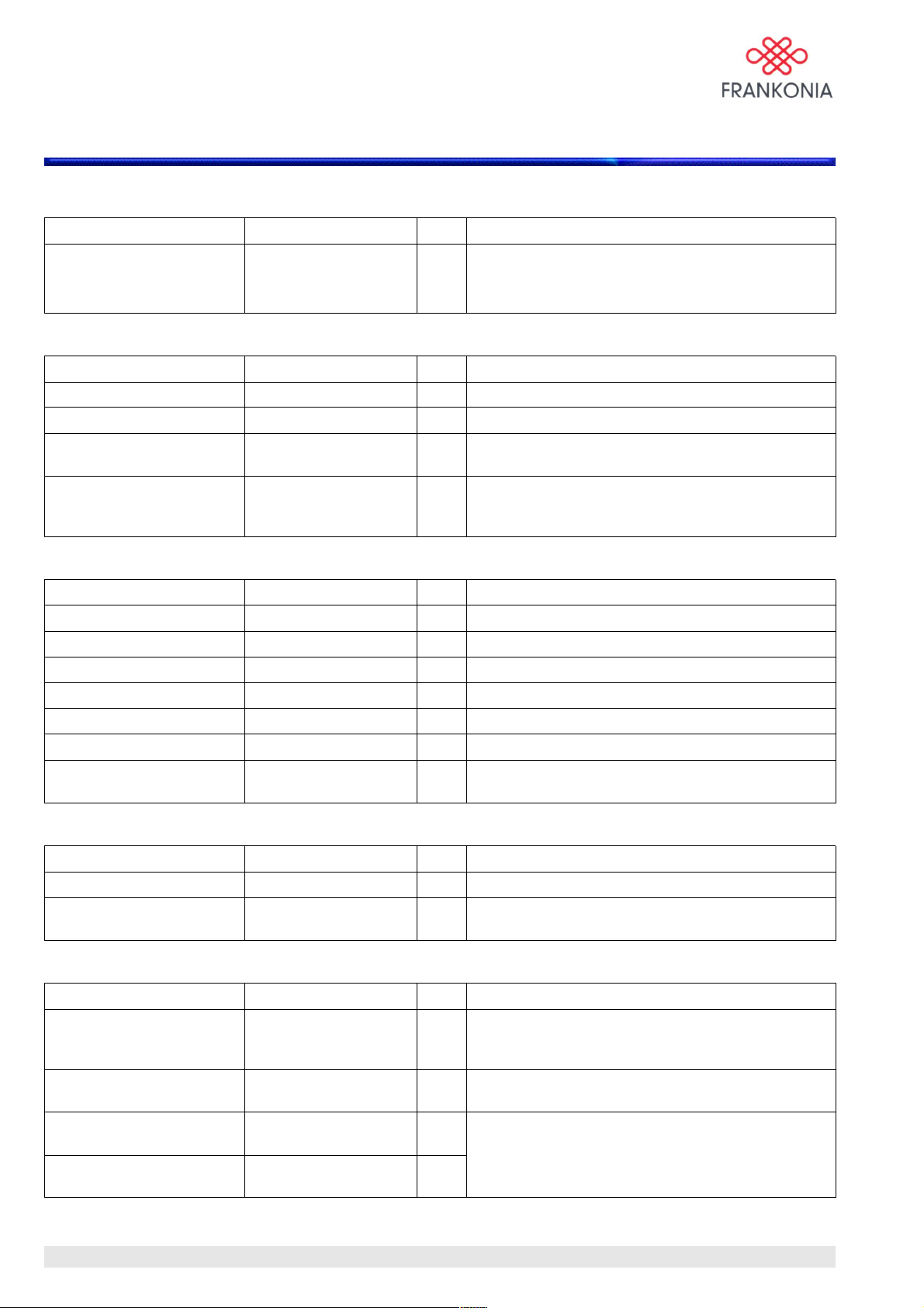
8.0 SCPI commands
Instrument subsystem:
Command Parameter Unit Result
INST[:SEL]{?}
INST:NSEL{?}
System subsystem:
Command Parameter Unit Result
SYST:ERR[:NEXT]? Query only Output and deletion of the last error in the error list.
SYST:VERS? Query only Output of the SCPI standard „1999.0“.
SYST:COMM:GPIB:ADDR{?}0...30 / MIN / MAX Setting of the GPIB address (saved in EEPROM,
SYST:COMM:SER[:REC]
:BAUD{?}
Status subsystem:
Command Parameter Unit Result
STAT:OPER[:EVEN]? Query only Output of the operation register.
STAT:OPER:COND? Query only Output of the operation condition register.
STAT:OPER:ENAB{?} 0...65535 Setting of the operation enable register.
STAT:QUES[:EVEN]? Query only Output of the questionable register.
STAT:QUES:COND? Query only Output of the questionable condition register.
STAT:QUES:ENAB{?} 0...65535 Setting of the questionable enable register.
STAT:PRES Reset of the operational/questionable enable
ANT / TTAB / ACL /
ANT2
1 / 2 / 3 / 4
1200 / 2400 / 4800 /
9600 / 19200 / MIN /
MAX
Selection of the logical equipment by keyword or
number. On ? output of the selected logical device.
default value: 15).
Setting of the RS232 baud rate (saved in EEPROM,
default value: 9600).
register.
Trigger subsystem:
Command Parameter Unit Result
INIT[:IMM] Starts a movement into the previously set direction.
ABOR Stops every started movement (even initialization
run).
Input/output subsystem for the antenna mast (ANT, ANT2):
Command Parameter Unit Result
POS[:X][:DIST][:IMM]{?} <NRf / 0.8...6> / MIN /
MAX / UP / DOWN
POS[:X][:DIST][:IMM]:STE
P{?}
POS[:X][:DIST]:LIM[1/2]:HI
GH{?}
POS[:X][:DIST]:LIM[1/2]:LO
W{?}
MA_FC02_(Rev2_1) - 9/06 / Version 1 / Rev:2.1
<NRf / 0...5.2> / MIN /
MAX
<NRf / 0.8...6> / MIN /
MAX
<NRf / 0.8...6> / MIN /
MAX
m The antenna mast moves to the programmed
position or direction, resp.. Upon inquiry, the actual
position is reported.
m Step width at POS UP / DOWN command.
m
m
18 / 24
Upper and lower limit value for the antenna with
horizontal [1] and vertical [2] polarization.
Page 19

Command Parameter Unit Result
POS[:X][:DIST]:OFFS[1/2]{
?}
<NRf / ±1> / MIN /
MAX
POS[:X][:DIST]:VEL{?} <NRf / 1...30> / MIN /
m Offset with horizontal [1] and vertical [2] polarization.
Velocity in steps.
MAX
POS[:X][:DIST]:DIR{?} UP / DOWN Determination of direction, however no automatic
movement.
[POS:]POL{?}
<NRf / ±/2> / MIN /
rad Turns antenna into the programmed position.
MAX
[POS:]POL:HOR Turns antenna into vertical polarization.
[POS:]POL:VERT Turns antenna into horizontal polarization.
Input/Output subsystem for the turntable (TTAB):
Command Parameter Unit Result
POS[:X]:ANGL[:IMM]{?}
<NRf / ±200> / MIN /
MAX / UP / DOWN
POS[:X]:ANGL[:IMM]:STEP
{?}
<NRf / 0..200> / MIN /
MAX
POS[:X]:ANGL:LIM:HIGH{?}<NRf / 0..200> / MIN /
MAX
POS[:X]:ANGL:LIM:LOW{?
}
POS[:X]:ANGL:OFFS{?}
<NRf / -200..0> / MIN /
MAX
<NRf / ±200> / MIN /
MAX
POS[:X]:ANGL:VEL{?} <NRf / 1..30> / MIN /
MAX
POS[:X]:ANGL:DIR{?} UP / DOWN Determination of direction (UP = clockwise), but no
deg The turntable moves into the programmed position,
or direction, resp. (UP = clockwise). On inquiry, the
actual position is reported.
deg Step width at POS UP / DOWN command.
deg
Upper and lower limit value of the position.
deg
deg Offset of the position. The limit values remain
unchanged!
Velocity in steps.
automatic movement.
Input/Output subsystem for the clamp line (ACL):
Command Parameter Unit Result
POS[:X][:DIST][:IMM]{?} <NRf / 0...10> / MIN /
MAX / UP / DOWN
POS[:X][:DIST][:IMM]:STE
P{?}
<NRf / 0...10> / MIN /
MAX
POS[:X][:DIST]:LIM:HIGH{?}<NRf / 0...10> / MIN /
MAX
POS[:X][:DIST]:LIM:LOW{?}<NRf / 0...10> / MIN /
MAX
POS[:X][:DIST]:OFFS{?}
<NRf / ±1> / MIN /
MAX
POS[:X][:DIST]:VEL{?} <NRf / 1...30> / MIN /
MAX
POS[:X][:DIST]:DIR{?} UP / DOWN Determination of direction, but no automatic
MA_FC02_(Rev2_1) - 9/06 / Version 1 / Rev:2.1
m The absorber clamp moves into the programmed
position, or direction, resp.. On inquiry, the actual
position is reported.
m Step width at POS UP / DOWN command.
m
Upper and lower limit value for the position.
m
m Offset for the position.
Velocity in steps.
movement.
19 / 24
Page 20

{?} Command is valid as command (without “?”) and valid as query (with “?”).
Commands in brackets [ ] are optional.
All position commands may be preceded optionally by the commands [INP:] or [OUTP:]
(i.e. INP:POS ≙ OUTP:POS ≙ POS)! This applies also for the Input/Output Subsystems for the turntable
(TTAB) and the clamp line (ACL). The parameter ANT2 is also valid in its long version ANTenna2.
<NRf / value>: Numerical entries are admissible optionally with prefix and exponent. Value is the valid
numerical range. The value can be followed by a unit. For indication of lengths mm, cm and m are valid,
for angles deg and rad. The values have to be converted correspondingly.
Numerical outputs are always in standard units (see tables). With respect to MIN and MAX the maximum
and minimum values are used.
On inquiries with MIN and MAX (? followed by parameter), the valid minimum and maximum values
(e.g. POS? MAX) are reported.
MA_FC02_(Rev2_1) - 9/06 / Version 1 / Rev:2.1
20 / 24
Page 21

IEEE 488.2 Status Registers
There are four status registers with the associated enabled registers. The positive transmission and
negative transmission registers (PTR/NTR) as defined in IEEE488.2, are not variable and definitely fixed
with PTR=255 and NTR=0. The sum bits in the STB are switched via the enable registers and linked via
„or“.
Status Byte (STB):
0 not used (always 0)
1 not used (always 0)
2 not used (always 0)
3 QUEST (sum bit of the questionable status register)
4 MAV (Message available), message available in the output buffer.
5 ESB (sum bit of the event status byte)
6 MSS/RQS (Master status sum / service request)
7 OPER (sum bit of the operation status register
Event Status Register (ESB):
0 OPC (Operational Complete)
1 not used (always 0)
2 Query Error (Query error, i.e. an answer has been requested but not queried)
3 Device Dependent Error (equipment error)
4 Execution Error (execution error)
5 Command Error (command error)
6 not used (always 0)
7 Power on (Controller was switched on)
Operation Status Register (OPER):
0 Calibration (sum bit, at least one logical device performs a calibration)
1-7 not used (always 0)
8 Moving (sum bit, at least one logical instrument performs a movement)
9 Moving ANT (instrument ANT performs a movement)
1 Moving TTAB (instrument TTAB performs a movement)
1 Moving ACL (instrument ACL performs a movement)
12 Moving ANT2 (instrument ANT2 performs a movement)
13-15 not used (always 0)
Questionable Status Register (QUEST):
0-7 not used (always 0)
8 Calibration (sum bit, calibration of at least one logical device has failed
9 Calibration ANT (calibration of instrument ANT has failed)
10 Calibration TTAB (calibration of instrument TTAB has failed)
11 Calibration ACL (calibration of instrument ACL has failed)
12 Calibration ANT2 (calibration of instrument ANT2 has failed)
13-15 not used (always 0)
MA_FC02_(Rev2_1) - 9/06 / Version 1 / Rev:2.1
21 / 24
Page 22
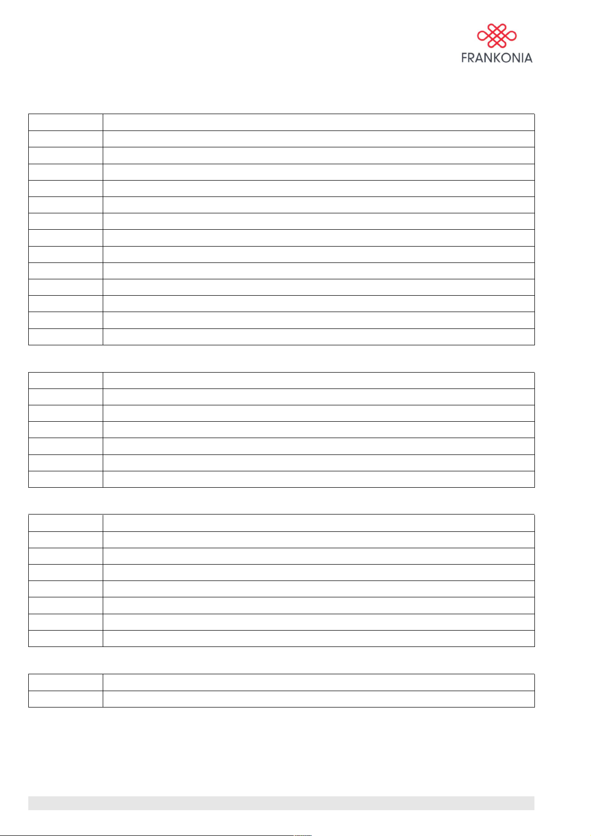
SCPI Error Code
Command error
Error code Error Description
0 No error
-100 Command error
-101 Invalid character
-102 Syntax error
-103 Invalid separator
-104 Data type error
-108 Parameter not allowed
-109 Missing parameter
-110 Command header error
-120 Numeric data error
-130 Suffix error
-140 Character data error
-150 String data error
Executing error
Error code Error Description
-200 Execuiting error
-213 Init ignored
-221 Setting conflict
-222 Data out of range
-224 Illegal parameter value
-240 Hardware error
Device specific error
Error code Error Description
-300 Device specific error
-310 System error
-315 Configuration memory lost
-330 Self test failed
-340 Calibration failed
-350 Queue overflow
-360 Communication error
Query error
Error code Error Description
-400 Query error
MA_FC02_(Rev2_1) - 9/06 / Version 1 / Rev:2.1
22 / 24
Page 23
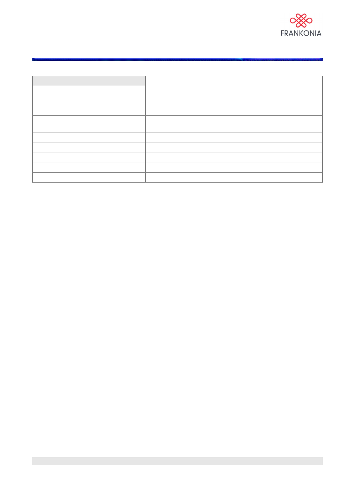
9.0 Specifications
FC 02
Power Supply 115/230 V
Power Line Frequency 50 / 60 Hz
Power Consumption 5 W average
Width x Depth x Hight 482,6 x 172 x 44,3 mm
(19 x 6,77 x 1,74 inches)
Weight 2,5 Kg
Standard Programming Languages SCPI
Remote Interface GPIB (IEEE488.2) and RS-232 (Baud rate 9600)
Optical Input / Output 660 nm, FSMA connectors
Accessories included Power cord, application software, User Manual
Notice
• The information contained in this document is subject to change without notice.
• For current specifications please contact the Frankonia sales department.
MA_FC02_(Rev2_1) - 9/06 / Version 1 / Rev:2.1
23 / 24
Page 24

FRANKONIA GmbH
Industriestraße 16
91180 Heideck / Germany
TEL: ++49-(0)9177-98500
FAX: ++49-(0)9177-98520
[email protected]
www.Frankonia-EMC.com
MA_FC02_(Rev2_1) - 9/06 / Version 1 / Rev:2.1
24 / 24
 Loading...