

Page 1

Safty Instructions
Important: Read Before Commissioning
• The user must ensure that all operators are familiar with this operating manual and
follow it at all times.
• The operating manual must be read carefully before the instrument is mounted,
installed and commissioned.
• All actions taken must follow the operating manual.
• Installation and commissioning may only be carried out by appropriately qualified
personnel with due regard for all rules and regulations that are in force.
• When the instrument is connected to mains voltage, it must not be opened.
• If the instrument is visibly damaged, it must not be installed, wired up or
commissioned.
• If the instrument does not work after commissioning, it must be disconnected from
the mains.
• Any further laws, standards, guidelines, etc. relevant to this product must be
complied with.
Additional information on EML 1101 Maximum Demand Controller and Add-on
station EMD1101
• Loads which may cause damage or danger when disconnected by EML1101 or
EMD1101 must not be connected to the load channels.
• The responsibility for correct load settings, such that proper operation is
guaranteed and no damage or danger arises, remains 100% with the customer.
1
Page 2

Operating manual EMD1101 Table of contents
Table of contents
Contens Page
1 Quick Start .................................................................................................................................3
2 Description.................................................................................................................................4
2.1 Function.......................................................................................................................................4
2.2 Function on fault ..........................................................................................................................4
3 Installation..................................................................................................................................5
3.1 Mounting......................................................................................................................................5
3.2 Electrical connection....................................................................................................................5
4 Commissioning..........................................................................................................................6
4.1 Defining the consumer status on fault .........................................................................................6
5 Basic settings ............................................................................................................................7
5.1 Setting the station number ..........................................................................................................7
5.2 Testing.........................................................................................................................................7
6 Operation....................................................................................................................................8
7 Technical data............................................................................................................................9
8 Troubleshooting ..................................................................................................................... 10
9 Connection diagram............................................................................................................... 11
2
Page 3

Quick Start Operating manual EMD1101
1 Quick Start
• Installation:
Important:
The connections for the power supply voltage are externally
protected by 2A semi-time lag fuses. When working on the
EML1101 the device must be switched voltage free.
Caution: Do not switch on the a power supply before the upper
housing unit has again been assembled!
• Undo the screws on the side.
• Remove the black base.
• Attach the base and terminal strip on the rail from the top.
• Insert the cable.
• Connect the cable to the appropriate terminals as shown in Fig. 1,
Page 13.
• Turn the rotary switch to the required channel.
• Set the DIP switches to the required fault status.
• Replace the upper housing unit.
• Switch on the mains power supply.
Important:
When working with the EMD1101, please note that,
although the circuits leading to the switch contacts are
isolated from the power supply, they can still conduct a
power voltage.
Note: After switching on the power supply the instrument requires
about 10 s for initialisation. All relays are open during this
time!
3
Page 4

Operating manual EMD1101 Description
2 Description
The EMD 1101 add-on station is used to increase the number of consumer
channels which are controlled by the EML 1101 maximum optimisation
computer. Every EMD 1101 add-on station provides 8 additional consumer
channels.
The EMD 1101 add-on stations are connected to the EML 1101 maximum
optimisation computer via the add-on bus. Depending on the type of EML 1101
maximum optimisation computer, up to 4 or max 10 EMD 1101 add-on stations
can be connected to the add-on bus. Thus there are a total of maximum 36 or
84 consumer channels available.
2.1 Function
The EMD 1101 add-on stations are connected to the EML 1101 maximum
optimisation computer via the add-on bus. Control commands are received from
this device when a particular consumer channel is to be switched on or off.
The actual status of the consumer channels can be seen from the LEDs on the
front plate. Thus a lit LED corresponds to a closed relay contact and therefore a
switched-on consumer channel.
A DIP switch labelled "Consumer on fault" is on the front plate. This is used for
defining the status fault of every consumer channel.
A rotary switch labelled "Station number". is on the front plate This is used for
assigning the station number which the EMD 1101 add-on station is to have for
the add-on bus.
An LED labelled "Access" is on the front plate. This flashes when data is
exchanged with the EMD 1101 add-on station. On fault, this LED is unlit and the
set consumer status on fault is given.
2.2 Function on fault
maximum optimisation computer and the EMD 1101 add-on station, the
EMD1101 add-on station automatically issues the set consumer status on fault.
Once there is successful connection, the EMD 1101 add-on station again issues
the preset consumer status from the EML 1101 maximum optimisation
computer.
From a specified lower operating voltage limit the EMD 1101 add-on station
gives the defined consumer status on fault.
Note: Even when the mains supply is isolated the consumer status on
fault is given.
4
Page 5

Installation Operating manual EMD1101
3 Installation
3.1 Mounting
•
Undo the screws on the side.
• Remove the black base.
• Attach the base and terminal strip on the rail from the bottom.
3.2 Electrical connection
•
Insert the cable.
• Connect the cable to the appropriate terminals as shown in Fig. 1, Page 13.
• Replace the upper housing unit and secure it using the two screws on the
side.
Caution: Do not switch on the power supply before the upper housing
unit has again been assembled!
5
Page 6

Operating manual EMD1101 Commissioning
4 Commissioning
4.1 Defining the consumer status on fault
•
Set the consumer status required on fault using the DIP switches labelled
”Consumer on fault ”.
The "On" position of a switch therefore means that the consumer is switched
on in cases of fault.
Note:
There are two basic ways of looking at the consumer status on fault:
• On fault, you wish to have the greatest number of consumers available on
the network. Therefore, set the consumer status on fault to "On". The set
reference power may be exceeded under certain circumstances.
• Under no circumstances do you want the set reference power to be
exceeded.
Therefore, set the consumer status on fault to "Off". In this case the
corresponding consumers are not available.
6
Page 7

Basic settings Operating manual EMD1101
5 Basic settings
5.1 Setting the station number
•
Turn the rotary switch labelled "Station number" on the front plate to the
station number (channel) required.
Note:
• Station numbers can be selected from 1 to 10 with ”0” standing for 10.
• For one EML 1101 maximum optimisation computer with up to 4 EMD
1101 station numbers can be selected from 1 to 4.
• For one EML 1101 maximum optimisation computer with up to 10 EMD
1101 add-on units station numbers can be selected from 1 to 10.
• The EMD 1101 add-on stations connected to one EML 1101 maximum
optimisation computer may not have the same station number!
5.2 Testing
•
Switch on the power supply.
Note: After switching on the power supply, the instrument requires about
10 seconds for initialisation. During this time all relays are open!
• Connect and configure the maximum optimisation computer. Note especially
that the corresponding EMD 1101 add-on station is activated. The EMD 1101
add-on station indicates correct operation by the flashing "Access" LED.
• Set a non-activated station number in the EML 1101 maximum optimisation
computer. The "Access" LED now stops flashing and the consumer status on
fault is given.
• Set the correct station number again. The "Access" LED starts flashing again
and the consumer status must assume the preset status of the EML 1101
maximum optimisation computer.
If this is not the case then please read Section 8, ”Instructions on
commissioning and trouble-shooting”.
7
Page 8

Operating manual EMD1101 Operation
6 Operation
The EMD 1101 add-on station has no operating elements and requires no
operation at the instrument itself.
8
Page 9

Technical data Operating manual EMD1101
7 Technical data
Mechanical construction:
Housing: Grey plastic
Dimensions ( W x H x D ) 158 x 75 x 120 mm
Weight: approx. 0.8 kg
Power supply:
Power voltage: 230VAC, -15 to +10%
Frequency: 50 to 65 Hz
Power consumption: 4VA
Outputs:
General: Relay contacts for 250VAC, 4A
8 switching channels ( 1..8 )
Operating conditions:
Ambient temperature: 0°C to +45°C
Storage temperature: -20°C to +60°C
Ingress protection: IP40
9
Page 10

Operating manual EMD1101 Troubleshooting
8 Troubleshooting
Pos. Error display Possible cause Remedy
1 "Access" LED does not
flash and consumer
status on fault switched
2 The delay time of 10
3 An incorrect station
4 The connection to the
5 The maximum
6 The EML 1101
7 Consumer status has
not been switched.
8 The EML 1101
9 The EML 1101
Operating voltage is
either incorrect or not
present.
sec has not yet
expired.
number has been set.
EML 1101 maximum
optimisation computer
is not correct or is
faulty.
optimisation computer
has not been
configured correctly.
maximum optimisation
computer does not
operate correctly.
An incorrect station
number has been set.
maximum optimisation
computer has not
been configured
correctly.
maximum optimisation
computer does not
operate correctly.
Check if the operating voltage is
correct.
Wait for delay time.
Set the correct station number.
Check connection to the EML 1101
maximum optimisation computer.
(Have connection A and B been
swapped over?)
Is the add-on station activated?
Check maximum optimisation
computer.
Set the correct station number.
Is the add-on station activated?
Check maximum optimisation
computer.
(Is the add-on station activated?)
10
Page 11
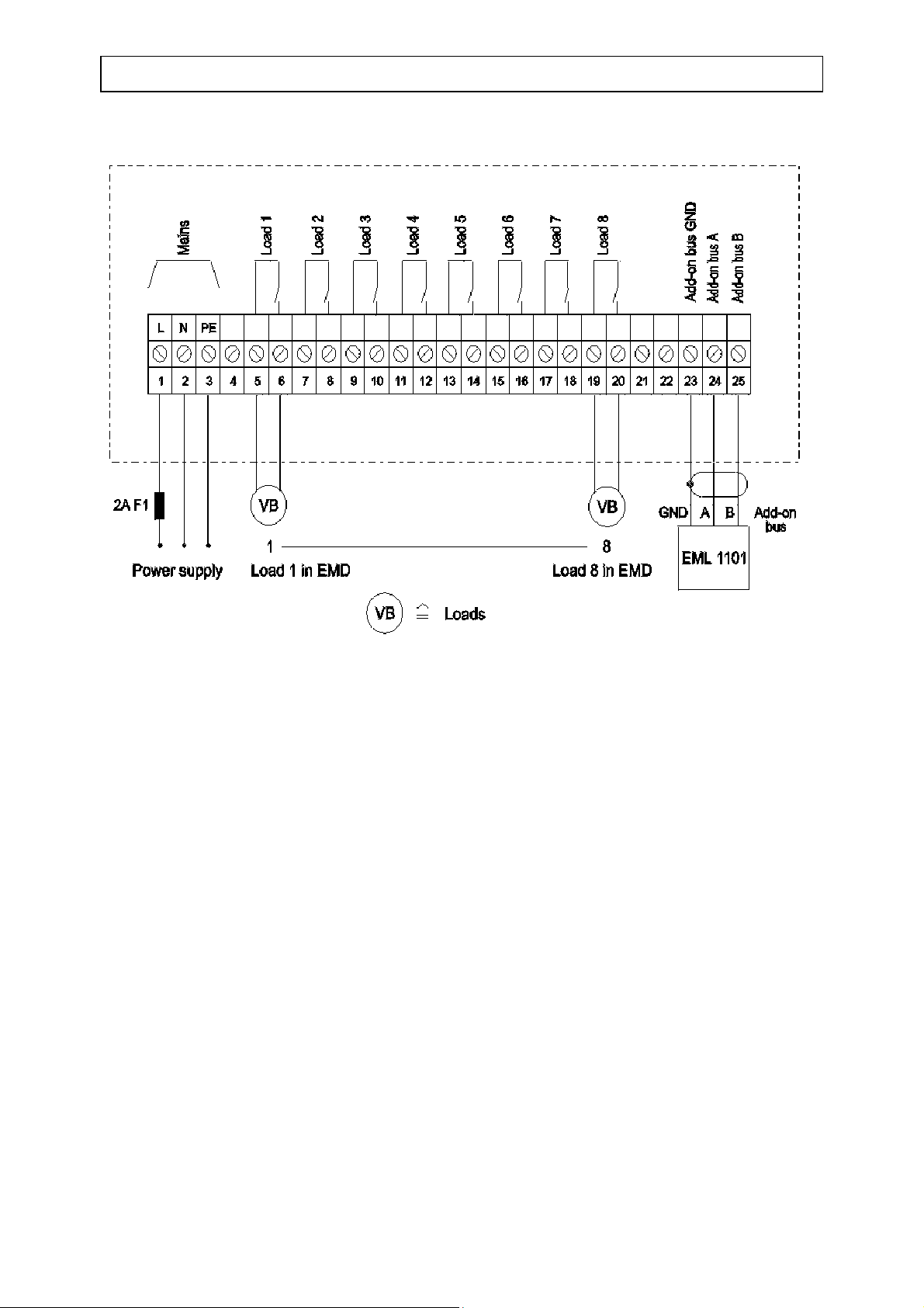
Connection diagram Operating manual EMD1101
9 Connection diagram
11
 Loading...