

Page 1
Axe-Fx
Pre-Amp /
Effects Processor
User’s Manual
Firmware Rev 5.xx
Page 2

Table of Contents
Table of Contents .............................................................................. 1
Foreword............................................................................................ 3
Introduction........................................................................................ 5
What is the Axe-Fx.................................................................................... 5
Concept..................................................................................................... 7
Getting Set Up................................................................................. 10
Rear Panel .............................................................................................. 10
Front Panel . ............................................................................................. 11
Example Connections ............................................................................. 13
I/O Configuration..................................................................................... 16
Editing.............................................................................................. 21
Placing Effects......................................................................................... 21
Routing.................................................................................................... 21
Moving Effects......................................................................................... 22
Editing Effects ......................................................................................... 22
Effect Mixer ............................................................................................. 22
Output Mixer . ........................................................................................... 24
Attaching Controllers............................................................................... 24
Saving Presets........................................................................................ 24
Recalling Presets .................................................................................... 24
The Effects....................................................................................... 26
Noise Gate .............................................................................................. 26
Compressor............................................................................................. 26
Filter ........................................................................................................ 27
Graphic Equalizer.................................................................................... 28
Parametric Equalizer............................................................................... 29
Chorus..................................................................................................... 29
Flanger.................................................................................................... 31
Phaser..................................................................................................... 33
Rotary Cabinet ........................................................................................ 34
Wah-Wah ................................................................................................ 35
Formant Filter.......................................................................................... 36
Pan / Tremolo.......................................................................................... 37
Delay....................................................................................................... 38
Multi Delay............................................................................................... 42
Reverb..................................................................................................... 46
Amp Simulator......................................................................................... 48
Cabinet Simulator.................................................................................... 56
Drive........................................................................................................ 58
Pitch Shifter............................................................................................. 59
Stereo Enhancer ..................................................................................... 64
Effects Loop / Aux. Out ........................................................................... 64
Page 3

Mixer........................................................................................................ 65
Volume / Pan........................................................................................... 66
Feedback Send / Return ......................................................................... 66
Controllers and Modifiers................................................................. 67
Tempo..................................................................................................... 67
LFO's....................................................................................................... 68
ADSR's.................................................................................................... 68
Sequencer............................................................................................... 69
Envelope ................................................................................................. 69
Pitch ........................................................................................................ 70
External Controllers................................................................................. 70
Modifiers.................................................................................................. 70
Global Parameters........................................................................... 73
Tuner ............................................................................................... 74
Utilities............................................................................................. 75
LCD......................................................................................................... 75
Preset...................................................................................................... 75
Status...................................................................................................... 76
Reset....................................................................................................... 76
Firmware ................................................................................................. 77
Tips and Tricks ................................................................................ 78
Achieving ultimate tone........................................................................... 78
Using Your Axe-Fx with a Guitar Amp..................................................... 78
Using Your Axe-Fx Live........................................................................... 79
Interference............................................................................................. 79
Maintenance............................................................................................ 80
Warranty Information....................................................................... 81
Specifications................................................................................... 82
Page 4

PORTANT SAFETY INSTRUCTIONS
WARNING:
To reduce the risk of fire or electric shock, do not expose this appliance to rain or
moisture.
CAUTION:
To reduce the risk of fire or electric shock, do not remove screws. No user-
serviceable parts inside. Refer servicing to qualified service personnel.
IMPORTANT SAFETY INSTRUCTIONS
1. Obey all warnings on the Axe-Fx Ultra and in this User’s Guide.
2. Keep away from sources of heat such as he at registers or appliances which prod uce
heat.
3. Connect only to a proper AC outlet of 100 - 240 V, 47 - 63 Hz.
4. Keep power cord in good condition. Do not kink, bend or pinch. If power cord
becomes damaged discard and replace.
5. If not using your Axe-Fx Ultra for extended periods of time disconnect from AC
mains.
6. Protect the unit from rain and excessive moisture.
7. Refer servicing to qualified personnel only.
8. Do not operate the unit and obtain service if:
• Liquids or excessive moisture enter the unit
• The unit operates incorrectly or performance is inconsistent or erratic
• The unit has been dropped and/or the enclosure damaged
Prolonged exposure to high volume levels can cause hearing loss and/or damage.
9.
Use of hearing protection in high volume situations is recommended.
1
Page 5

Certificate of Conformity
Fractal Audio Systems, USA, hereby declares on own responsibility that the following product
Axe-Fx - Digital Guitar Preamp / Effects Processor
That is covered by this certificate and marked with CE label conforms with following standards:
EN60065
(IEC 60065)
EN 55103-1 Product family standard for audio, video, audio-visual and
EN 55103-2 Product family standard for audio, video, audio-visual and
With reference to regulations in following directives: 73/23/EEC, 89/336/EEC
Safety requirement for mains operated electronic and related
apparatus for household and similar use.
entertainment lighting control apparatus for professional use.
Part 1: Emission.
entertainment lighting control apparatus for professional use.
Part 2: Immunity.
Issued in February 2007
Clifford Chase
President
EMC / EMI
This equipment has been tested and found to comply with the limits for a Class B Digital device,
pursuant to part 15 of the FCC rules.
These limits are designed to provide reasonable protection against harmful interference in
residential installations. This equipment generates, uses and can radiate radio frequency energy and,
if not installed and used in accordance with the instructions, may cause harmful interference to radio
communications. However, there is no guarantee that interference will not occur in a particular
installation. If this equipment does cause harmful interference to radio or television reception,
which can be determined by turning the equipment off and on. Th e user is encouraged to try to
correct the interference by one or more of the following measures:
• Reorient or relocate the receiving antenna.
• Increase the separation between the equipment and receiver.
• Connect the equipment into an outlet on a circuit different from that to which the receiver is
connected.
• Consult the dealer or an experienced radio/TV technician for help.
2
Page 6

Foreword
Foreword
Shortly after the advent of the electric guitar and the amplifier, guitar players began to experiment
with altering the basic sound of their instruments. Amplifiers soon began to incorporate spring
reverb units and then tremolos and overdrive circuitry. Never satisfied, guitarists yearned for even
more sonic possibilities and the effect pedal was born. These early pedals were based on discrete
semiconductors and consisted of wah-wah, distortion and other simple effects. Although crude,
folklore has exalted these early pedals to the point where some feel they were endowed with almost
mystical properties due to their germanium transistors or the particular manufacturer of inductors.
With the introduction of the integrated circuit (IC) in the late 1960's designers could now realize
more complicated effects. Notable among these were the operational amplifier and later on the
bucket-brigade delay line, the latter allowing compact time-based effects to become a reality. By
the 1970's a myriad of effect pedals were available to the musician from many different
manufacturers. Chorus, phaser and flanger effects became ubiquitous and pervaded the recordings
of the time. Many of these pedals were noisy and lacked fidelity, the analog delay lines contributing
to significant signal degradation.
As technology marched on and IC's became ever denser, a new paradigm was thrust into the
spotlight: digital. Digital effects, it was promised, would offer far superior performance: zero noise,
nearly infinite delay times, pristine reverbs, etc. Soon the multi-effect was born. In a single rackmounted unit the guitarist could have the equivalent of a dozen different effect pedals. Competition
was fierce with each manufacturer trying to one-up the other by cramming more and more into their
boxes. Ultimately, and unfortunately, this has led to digital's demise.
As engineering gave way to marketing, many soon began to question the Emperor's new clothes.
Pricing pressures and cost cutting forced engineers to use low-grade components and inferior
algorithms, and the quality of the effects suffered. Grainy, cheesy, noisy. No doubt many have heard
these terms when referring to digital effects. Soon, many guitarists rebelled against digital effects
and analog pedals have now enjoyed a renaissance. Old analog pedals are prized and sought among
vintage collectors. Musicians have ditched their rack processors in favor of a board full of
individual effect pedals.
But this is a pity. For digital does not have to carry the stigma that it does. Digital is, in fact, quite
capable of delivering the benefits that were originally touted. And now, more than ever, can this be
realized, as modern Digital Signal Processors (DSP's) are not only incredibly powerful but
relatively inexpensive. The quality of digital audio is hard to refute. Just witness CD and DVD
players, MP3 devices and computer audio in general all of which use digital processing.
Furthermore, digital offers the convenience of multiple simultaneous effects, programmability and
superior control.
With the Fractal Audio Systems Axe-Fx
the superior solution to musical effects processing. Every aspect of the Axe-Fx has been designed
to deliver the ultimate in sonic quality. The converters are of the highest quality offering low-noise,
high linearity and uncolored performance. The DSP has more raw compute power than many
desktop computers allowing uncompromised processing algorithms. All processing is done at 32bit precision yielding uncolored, transparent sound.
TM
we have hopefully restored digital to its rightful place as
3
Page 7

Foreword
We hope you enjoy using the Axe-Fx as much as we enjoyed designing it. Over three years of
development have gone into making what we hope is the quintessential effects processor.
NOTE:
Fractal Audio Systems, Axe-Fx, Ultra and Dynamic Response Technology are trademarks of
Fractal Audio Systems. All other product names, trademarks, and artists’ names are the property of
their respective owners, which are in no way associated or affiliated with Fractal Audio Systems.
4
Page 8

Introduction
Introduction
Thank you for purchasing an Axe-Fx Pre-Amp / Effects Processor. You’re now the owner of one
of the most powerful instrument processors ever produced. By familiarizing yourself with this
manual you’ll be able to reap the full benefits of your unit. Please take a moment to read through
the sections that follow and acquaint yourself with the usage of your Axe-Fx.
What is the Axe-Fx
What is the Axe-Fx? Well, let's start by telling you what it isn't.
It's not a modeler in the strict sense. Although it has cabinet emulation and different amplifier
"types" it does not attempt to model any amplifier or effect exactly. Rather the Axe-Fx was designed
to simply provide the effect as originally intended and with the utmost quality. All effects can be
described in terms of their desired sonic manipulation. All effect processors, whether "stomp boxes"
or otherwise, process the input signal to get an output signal, simple as that. However, some
processors obviously do better than others. The Axe-Fx approaches effects processing as a strict set
of specifications and implements those specifications.
For example, the wah effect in the Axe-Fx is not intended to model any of the classic wah-wahs.
Instead the input-output relationship of a wah was distilled into a set of specifications. From there
the effect was designed to exactly meet these specifications. There is no "black magic" or
obfuscation. The effect does exactly what it should do. Inherent in this approach is a degree of
flexibility that you do not get with other processors. In our wah example this allows you to set the
sweep range, "Q" and other parameters. Most modeling processors do not allow this level of control.
The Axe-Fx’s amp, drive and cabinet simulations, however, are very faithful reproductions of the
originals, but without the drawbacks of the originals. What this means is that they sound like the
originals but are easier to adjust and provide more flexibility and a wider range of tones. For
example, the Brownface amp sim sounds remarkably like a particular classic amp however the AxeFx contains working midrange and presence controls. Also the tone controls are much more
responsive providing all the tones of the original plus new tones that the original could not achieve.
Once again the philosophy is practicality and presenting the “effect” as it was originally intended.
The Axe-Fx does not use any analog processing or any tubes. If you look inside
will not see any glowing tubes or any of the revered op-amps that the analog pundits claim offer
mystical sonic properties. What you will see are modern, high-quality components that offer
specifications and performance far exceeding any of the aforementioned devices.
The Axe-Fx does contain, however, very accurate digital replicas of actual vacuum tubes. We
gathered up some classic tubes and measured their transfer functions and then stored these transfer
functions in the Axe-Fx’s massive brain. Our replicas are so exact that we can reproduce the
harmonic spectrum of a real tube amp with amazing accuracy. Most modelers don’t even come
close.
1
the Axe-Fx you
1. Please do not open your Axe-Fx as damage may occur. Refer all servicing to qualified personnel.
5
Page 9

Introduction
OK, so what does it do? Well, the Axe-Fx is fully routable, fully programmable, real-time
controllable, multi-effects processor. Whew, that's a mouthful. Let's examine each of these
attributes:
Routabil ity:
the effects loop is routable as well so if you use your Axe-Fx with a preamplifier you can place the
preamplifier in the effects loop and run effects both before and after your preamp. Some effects
work better when placed before distortion (which your preamp would provide) and others work
better after. By providing a routable effects loop the Axe-Fx allows unrivaled flexibility.
Programmability:
You are not constrained by the limitations of "one-knob" processors where little if any editing of
parameters is offered. In addition, many effects offer advanced editing capability allowing in-depth
programming. Usability has not been sacrificed though as most effects have a basic setup page
allowing quick access to the most used parameters.
Controllability:
internal and external controllers can be attached to various parameters offering dynamic control of
an effect. Additionally these controllers allow mapping the control value to the effect parameter
through a transform so even greater control is afforded.
Multiple Effects:
effects you get two instances so you can really create some huge sounds. The Axe-Fx works on the
principle of an "effects inventory". You take an effect out of inventory and place it in the routing
grid and then connect it to other effects and connect controllers to it (if desired). If an effect has
multiple instances you can withdraw another instance of that same effect from the inventory and
place it at another location in the grid. The effects inventory is listed below along with the number
of instances available:
The Axe-Fx allows you to place effects in any order and in series or parallel. Also,
The Axe-Fx allows extensive programmability of each effects parameters.
Many of the parameters in the Axe-Fx are controllable in real-time. Both
The Axe-Fx has all the classic effects plus a few new ones. And for most
• Noise Gate (1)
• Compressor (2)
• Graphic Equalizer (2)
• Parametric Equalizer (2)
• Amplifier Emulator (2)
• Cabinet Emulator (2)
• Reverb (2)
• Chorus (2)
• Flanger (2)
• Phaser (2)
• Rotary Cabinet (2)
• Wah-Wah (2)
6
Page 10

Introduction
• Formant Synthesizer (1)
• Tremolo/Panner (2)
• Delay (2)
• Multi-Delay (2)
• Filter (2)
• Pitch Shifter (1)
• Drive (2)
• Stereo Enhancer (1)
• Mixer (2)
• Effects Loop (1)
• Feedback Send/Return (1)
Concept
Despite the huge arsenal of effects at your disposal, the Axe-Fx first-and-foremost emphasizes
sound quality. Unique to the processing in the Axe-Fx is our proprietary natural processing
algorithms. Many of the algorithms in the Axe-Fx replicate patterns that occur in nature (this is
where our company name was derived from). The reverb algorithm replicates the sound of a real
room, the chorus and flanger use special variable delay algorithms that are more natural and smooth
that any pedal (analog or digital) could ever achieve and the amp simulations use unique, dynamic,
non-linearity generators that produce smooth, even-ordered harmonics giving a depth to the sound
that other processors lack. Almost all the effects in the Axe-Fx are full stereo (except for the Amp,
Drive, Pitch and Multi-Delay effects) allowing for rich, full-sounding signal chains. And by using
two Amp blocks you can achieve a true stereo, dual-amp rig for really huge sounds.
Along with our superior algorithms the Axe-Fx uses the finest quality components available. The
op-amps, A/D and D/A converters and passive components are all of the highest quality. The
converters are the same converters used in high-end studio equipment costing many thousands of
dollars. A single op-amp in the Axe-Fx costs more than all the op-amps combined in many “budget”
processors. Additionally our unique analog topology eliminates any electrolytic capacitors from the
signal path. Only high-quality film capacitors and precision metal-film resistors are used in the
signal path assuring low-noise and low-distortion performance. These features also allow the AxeFx to excel as a general purpose outboard processor for studio and live use.
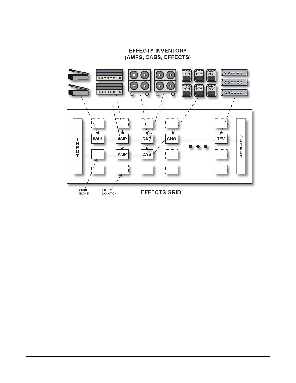
The Axe-Fx works on the concept of an effects inventory and an effects grid.
7
Page 11
Introduction
Figure 1. Axe-Fx Concept
The effects inventory is a virtual stockroom of effects. Effects are removed from the inventory and
placed into the effects grid. The grid is a four row by twelve column matrix. Once an effect has been
placed in the grid it can be connected to any other effect in an adjacent column. Routing beyond the
adjacent columns is not permitted. Figure 1 shows the conceptual model along with a somewhat
simple routing. The input feeds the “WAH” block which feeds an “AMP” block which in turn feeds
the “CAB” block, etc. A second series path has another amp and cab and this path is added to the
first path at the input to the chorus (CHO). Signal flow is always left-to-right. We’ll cover routing
in more detail later.
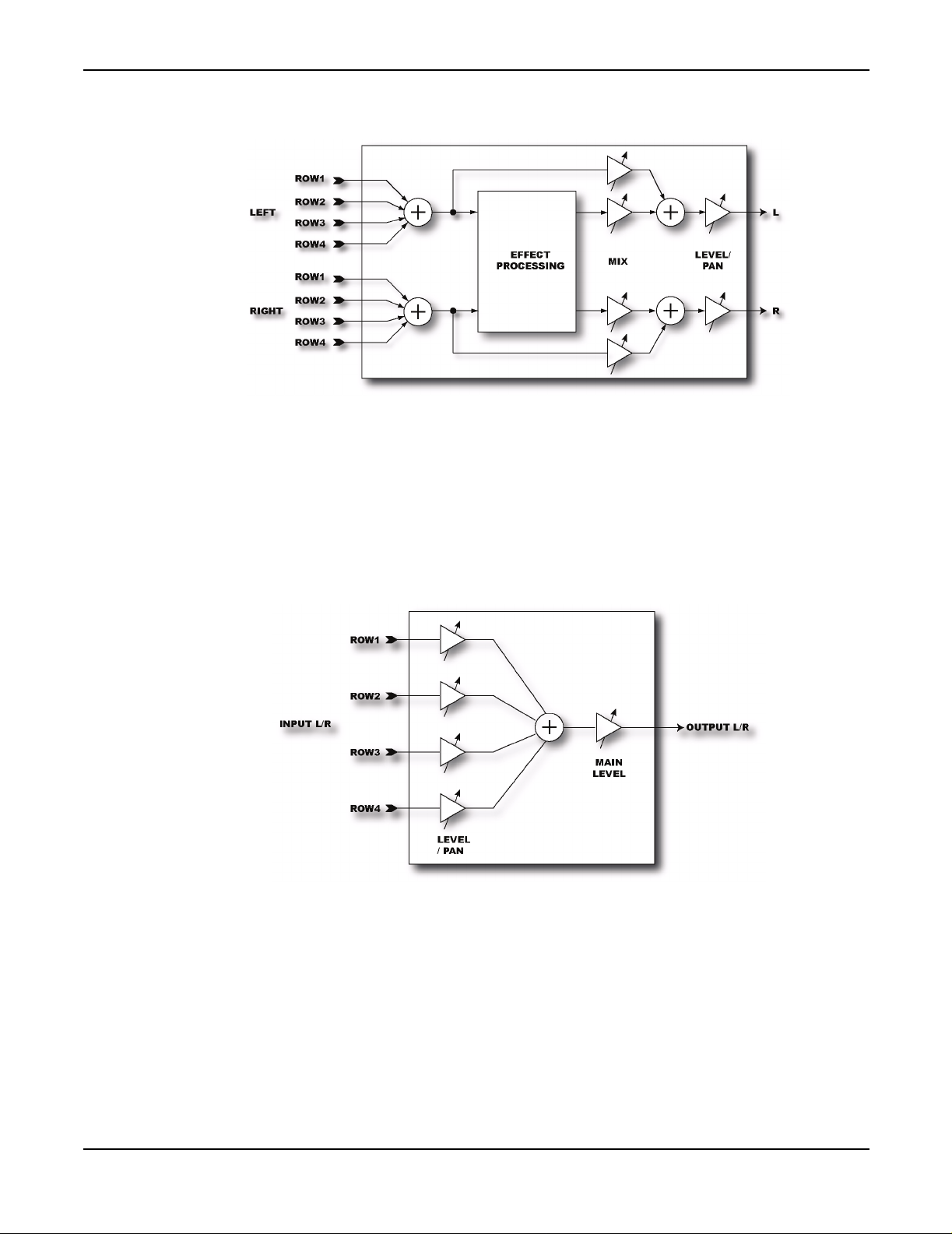
Every effect has a common input-output structure. The input sums the outputs of the effects that
feed into the effect. Each effect can have up to four inputs from the previous column. In turn each
effect can feed its output to up to four effects in the subsequent column.
8
Page 12
Introduction
Figure 2. Effect Block I/O Structure
The Output Mixer (the block labeled “OUTPUT” in Figure 1) sums the signals from the four rows.
The Output Mixer allows mixing and panning of the four rows and overall level control.
Figure 3. Output Mixer
9
Page 13
Getting Set Up
Getting Set Up
Rear Panel
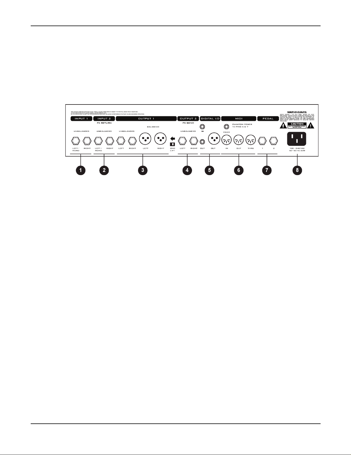
Figure 4. shows the rear panel of the Axe-Fx.
Figure 4. Rear Panel
1. Input1 -
use these jacks and be sure to set the
NOTE: The front panel
2. Input2 / Eff. Return -
here. You can also use this as a generic input by placing the effects loop block in the grid but not
connecting anything to the block’s input.
3. Output1 -
outputs are intended for use with a mixing board and balanced cables (mic cables). The unbalanced
outputs are intended for connecting to a power amp or other unbalanced equipment. The
LIFT
outputs flip this switch to isolate the ground.
4. Output2 / Eff. Send -
use this as an auxiliary output for on-stage monitoring or other uses.
5. Digital I/O -
configured to use the digital input,
Configuration). The
format is 24-bit / 48 kHz.
Connect line-level input sources to these jacks. If using the Axe-Fx as an effects processor
INPUT SOURCE
INSTR
Main outputs. There are two sets of outputs, unbalanced and balanced. The balanced
switch lifts the shield ground on the balanced outputs. If you get hum using the balanced
The IN connector provides 24-bit / 48 kHz digital input to the Axe-Fx. When
OUT
input is defeated whenever a plug is inserted into this input.
If using the effects loop the output of the effect(s) in the loop are connected
Connect this to the input of the effect(s) in your effects loop. You can also
INPUT1
connectors provide a digital version of the audio from
is defeated and the effects loop is not active (see I/O
to
ANALOG REAR
in the
I/O
menu.
OUTPUT1
GND
. The
10
Digital audio output is provided on both RCA and XLR connectors. Digital in is provided on an
RCA connector. You can connect and AES digital source (XLR connector) to the RCA digital input
jack using commonly available AES to SPDIF adaptor cables.
Page 14
Getting Set Up
6. MIDI -
power on pins 6 and 7 of
7. Pedal / Footswitch -
footswitches here. Each jack is a ¼" stereo jack capable of supporting an expression pedal or a
footswitch (either momentary or latching).
When connecting an expression pedal the pedal data can be used to control various parameters
continuously such as volume, rate, drive, etc. A footswitch would normally be used to control
bypass or preset recall. See the I/O Configuration section for more information on pedal types and
configuration.
8. A/C In -
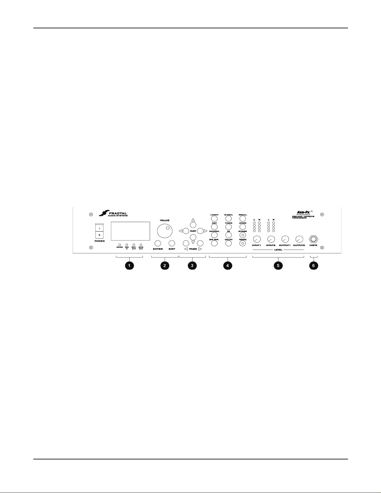
Front Panel
Figure 5 shows the front panel of the Axe-Fx.
MIDI interface. Connect your MIDI controller to
MIDI IN
Pedal / footswitch inputs. Connect your expression pedals and/or
Mains power. Connect to a grounded AC receptacle.
allowing phantom powering of pedal boards that support this.
MIDI IN
. The
POWER
jack provides
Figure 5. Front Panel
1. Status / Warning Indicators -
EDITED
MIDI IN OUT1 CLIP -
representable by 24-bits. Internally the Axe-Fx uses 32-bit floating-point numbers so clipping is
virtually impossible. These values are then converted to 24-bit fixed-point numbers prior to being
output. If the converted value is greater than that which can be represented by a 24-bit fixed-point
number, this will cause clipping of the D/A converter and clipping of the digital output. If the
clipping is severe audible distortion may result. Reduce the output level by either turning down the
level in one or more of the effect blocks or by turning the master output level down in the layout
mixer.
- Lit if the current preset has been edited, reminding you to save your changes.
Lights whenever MIDI data is received.
Lights whenever the digital signal level at
These four LED's consist of:
OUTPUT1
has exceeded that which is
11
Page 15

Getting Set Up
OUT2 CLIP -
representable by 24-bits. Reduce the output level by either turning down the level in one or more of
the effect blocks or by turning the master output level down in the effects loop mixer.
2. Value / Enter / Exit -
button is used to commit effects to a block, attach controllers and various other activities. The
button cancels dialogs and escapes from various states
3. Navigation -
switch between pages.
4. Menu -
Pressing a menu button brings you to that menu instantly:
LAYOUT -
GATE
and
effect once it's been placed. The
The
MIX
page allows overall mixing and panning of the four rows in the grid as well as overall
output level adjustment.
EDIT EDIT
in the grid.
To edit an individual effect, highlight that effect in the
. This brings up the edit pages for that effect. Pressing
Lights whenever the signal level at
The value dial is used to adjust values of various parameters. The
The four navigation buttons allow movement within a page. The
This is the effects grid placement and routing menu. There are four pages:
MIX
. The
EDIT
page is used to place and route effects. The
GATE
page contains the adjustable parameters for the Noise Gate.
OUTPUT2
EDIT
has exceeded that which is
MOVE
page allows moving an
LAYOUT>EDIT
again switches to the next effect
menu and press
PAGE
buttons
EDIT, MOVE,
ENTER
EXIT
CONTROL -
TEMPO, LFO1, LFO2, ADSR1, ADSR2, ENV
controllers section.
EFF. BYP -
of the effect in the grid will change to a dotted line indicating the effect has been bypassed. Pressing
the button again will restore the effect.
GLOBAL -
MIX
. These are discussed in more detail in the Global section.
TUNER I/O -
This button brings up the I/O Setup menu. This menu allows you to configure the various
audio and control options of the Axe-Fx. See the I/O Section for more details.
UTILITY RECALL STORE BYPASS -
bypass state. Press the button again to defeat the bypass. Pressing this button twice in rapid
succession restores all parameters of the selected effect to their default values.
Pressing
To bypass and individual effect, highlight the effect and press
This brings up the Global parameters menu. There are three pages:
Pressing this button brings up the tuner display.
This menu contains various utility functions. See the Utility section for more details.
Brings up the Recall display and allows you to recall presets using the value dial.
Enters the Store menu allowing naming and saving of the current preset.
Pressing this button bypasses the Axe-Fx. The LED on the button is lit indicating the
CONTROL
brings up the menu pages for the internal controllers. These are
and
MODS
. These are discussed in more detail in the
EFF. BYP.
OUT1, OUT2,
The outline
and
12
Page 16

Getting Set Up
TEMPO -
was tapped in. The tempo is saved with the preset but may be overridden at any time. Recalling a
preset loads the tempo of that preset. Any effects set to use tempo will adjust their dependent
parameters to the current tempo.
5. Level Controls
INPUT1/2 -
adjust the levels until the top red LED just barely lights on the strongest peaks. For example, adjust
INPUT1
should light only occasionally. Setting the level controls too high may result in clipping of the input
causing audible distortion. For guitars with humbucking pickups the
be around the 2:00 position. For single coils you may wish to set this control slightly higher.
For best results when plugging line-level devices into an input set the controls at midpoint and
adjust the output level of the device so that the red LED barely lights on the strongest signal peaks.
The LED’s indicate the signal level at the A/D converter. When the red LED lights the signal into
the A/D is 6 dB below full-scale (6 dB headroom).
OUTPUT1/2 -
connected to the outputs. Setting the levels too high may result in clipping of the attached
equipment. The Axe-Fx is capable of delivering about +18 dBu maximum with level controls at full.
Tap the song tempo using this button. The LED on the button flashes at the tempo that
These controls set the input levels to the A/D converters. For best signal-to-noise ratio
so that when you strum your guitar loudly with its volume all the way up the red LED
INPUT1
These controls set the output level of the Axe-Fx. Adjust these to suit the equipment
control will normally
6. Instr -
Plugging a line-level device into this input is not recommended as this may cause clipping of the
input amplifier. Be sure to set the
inserted into the
Plug your guitar into this jack. This input is conditioned especially for use with your guitar.
INPUT1 LEFT/MONO
Example Connections
Below are examples of the Axe-Fx in various configurations along with explanations and tips on
usage.
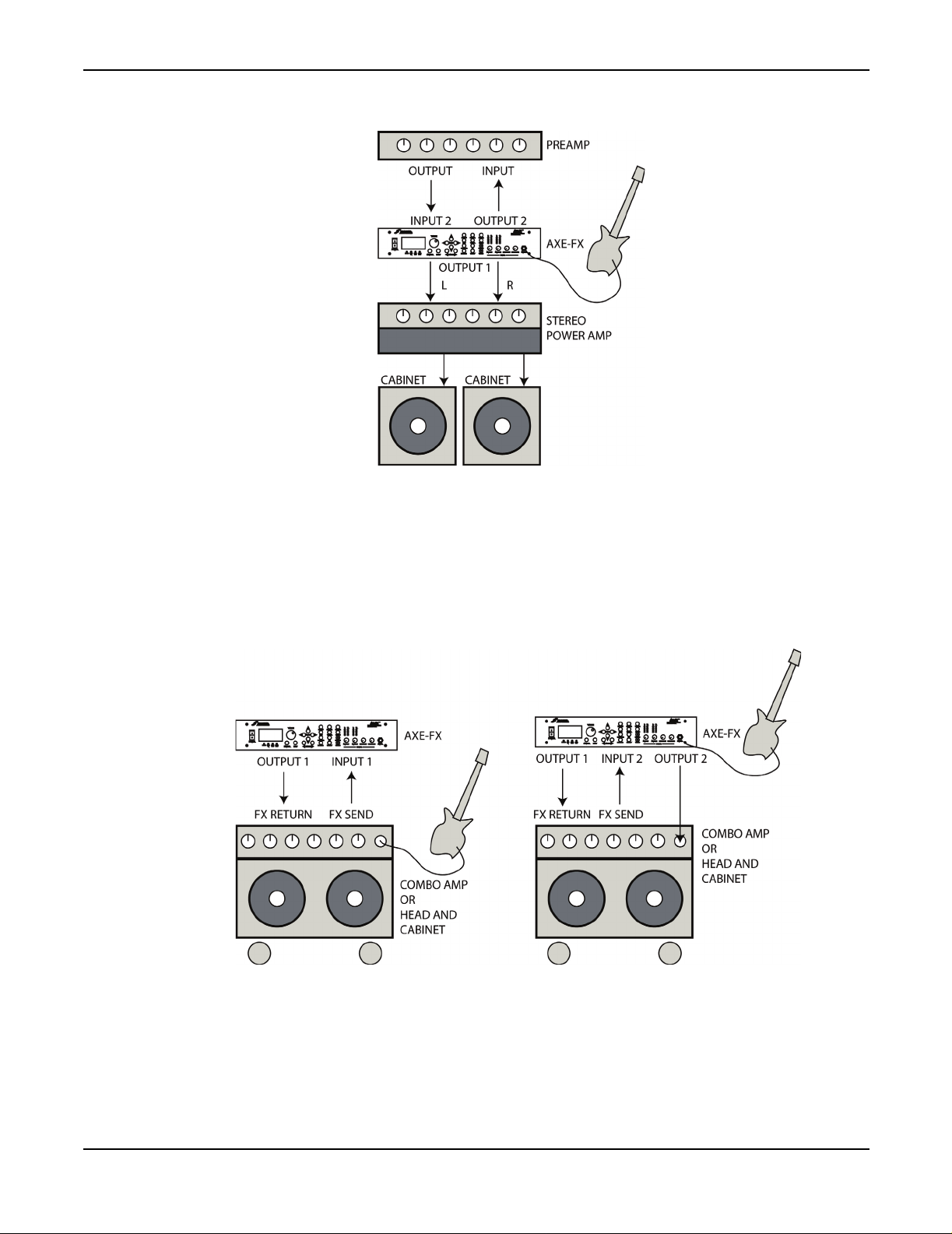
As an Effects Unit with Separate Preamp and Power Amp
The Axe-Fx can be used as an effects processor along with a dedicated preamp and power amp. In
this configuration the preamp provides the primary distortion and tone shaping while the Axe-Fx
provides effects. By using the preamp in the Axe-Fx’s effects loop you can place effects both before
and after the preamp. Certain effects, like wah and phaser, tend to work better before distortion,
whereas time-based effects such as delay, chorus, reverb, etc. sound best after distortion.
This configuration also allows you to use the Axe-Fx amp simulations as well. In this way you can
use the outboard preamp for certain sounds, and the Axe-Fx for others. Be warned, however, after
using the Axe-Fx’s amp sims you may find your preamp redundant and just adding unnecessary
weight to your rack!
INPUT SOURCE
jack on the rear panel this input is defeated.
to
ANALOG FRONT
in the
I/O
menu. If a plug is
13
Of course you can always use the Axe-Fx between the preamp and power amp, if desired, in the
classic post-distortion configuration.
Page 17
Getting Set Up
As an Effects Unit with a Combo Amp (or Head and Cab)
Below are two possible configurations for using the Axe-Fx with a combo amp (or head and
cabinet). In the first configuration the Axe-Fx is simply used in the effects loop of the amp. The
second configuration is more complicated but allows effects both before and after the amp’s preamp
stage. In this configuration you are using the amp in the Axe-Fx’s effects loop.
14
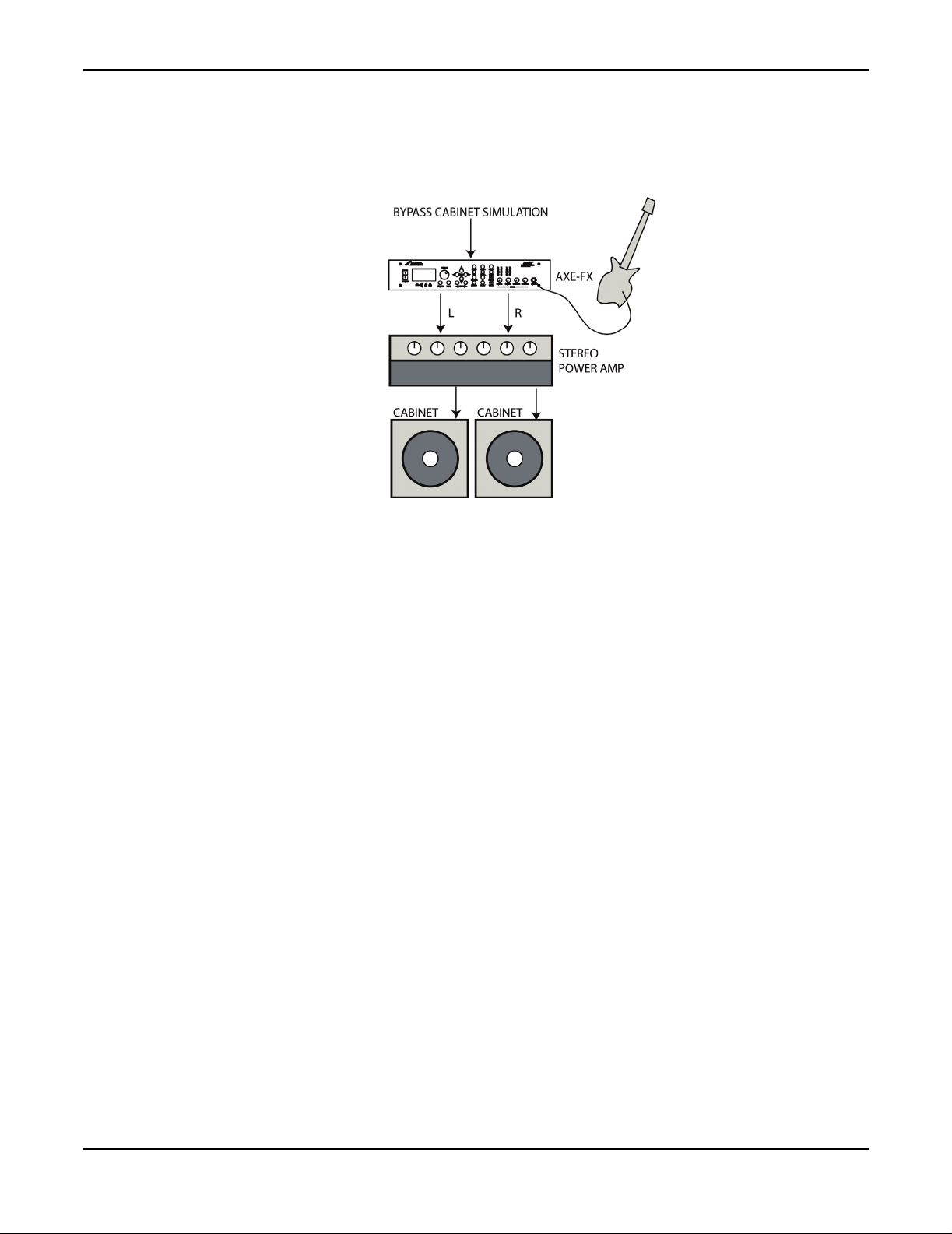
As a Preamp / Processor Into a Power Amp and Guitar Cabinet(s)
In this configuration the Axe-Fx is providing all distortion and tone-shaping. The output of the AxeFx is connected to a power amp and cabinets equipped with guitar speakers. Since the cabinets are
not full-range, the cabinet simulation in the Axe-Fx should be defeated. This can be done globally
Page 18
Getting Set Up
via the
GLOBAL
menu, or per-preset by bypassing the cabinet block or removing it from the signal
chain. If the power amp is a tube amp you may want to bypass the Axe-Fx power amp simulations
as well. This can be done via the
GLOBAL
menu, or per-preset by turning the
SAG
control fully
counter-clockwise.
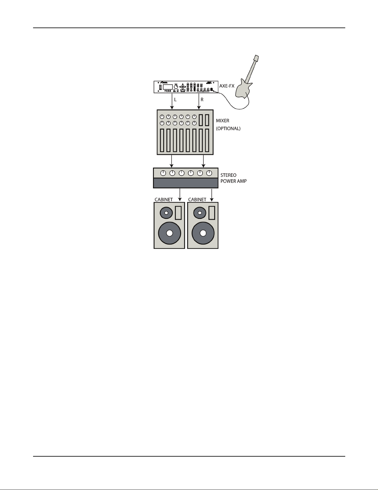
As a Preamp / Processor Into a Full-Range System
In this configuration the Axe-Fx is providing all distortion and tone-shaping. The output of the AxeFx is connected to a full-range sound reinforcement system. Since the system is full-range the AxeFx’s cabinet simulation should be active.
The configuration shown would be typical of using the Axe-Fx straight into a FOH mixer. Your
sound man would then send you your sound back into your stage monitor(s).
You can also use this configuration without the mixer as a stage rig. Simply connect the Axe-Fx
into a power amp and full-range speakers for the ultimate in tonal flexibility.
15
Page 19
Getting Set Up
Recording
Using the Axe-Fx in the studio is straightforward. Simply connect the main outputs (analog or
digital) to a mixer, computer, etc.
I/O Configuration
Press the
audio, MIDI and pedals of the Axe-Fx.
Mode Configuration
The first page of the
ANALOG FRONT
word clock. Setting to
to this bit stream.
The Axe-Fx can only run at 48 kHz. If you connect a digital source to the unit be sure that its sample
rate is 48 kHz.
Set the
conditioned to provide optimum noise performance for use with an electric guitar.
I/O
INPUT SOURCE
button to access the
I/O
menu configures the primary input source. Setting the
or
ANALOG REAR
DIGITAL
to
selects the
ANALOG FRONT
I/O
configuration menus. These menus allow you to configure the
INPUT SOURCE
configures the unit to slave all clocks to the internal 48 kHz
DIGITAL
when using the front-panel input. This input is
input as the main input and slaves all clocks
to
16
Page 20

Getting Set Up
Set the
INPUT SOURCE
to
ANALOG REAR
when using the rear-panel input. This input is a generic
line-level input and works with any line-level source.
Audio Configuration
The next page of the
desired mode for each of the inputs as follows:
LEFT -
panel
the rear panel
Use for monophonic input sources. For
INPUT1 - LEFT / MONO
INPUT2 - LEFT / MONO
right channel.
L+R SUM -
STEREO -
For the
STEREO -
Use when you wish to sum two sources using the
Select this if your input source is stereo.
MAIN OUT
Selecting this routes the left and right output signals to their respective output
connectors. This is the normal configuration for stereo use.
L+R SUM -
Selecting this sums the left and right and sends the summed signal to both output
connectors.
I/O
menu configures the inputs and main output of the Axe-Fx. Select the
jack (set
INPUT 1
INPUT SOURCE
use the front panel
jack. In this mode the left input signal is copied to the
:
INSTR
as described above). For
LEFT
and
RIGHT
input jacks.
jack or the rear
INPUT 2
use
L->R -
Selecting this copies the left data to the right channel and outputs this to both connectors.
MIDI Configuration
The
MIDI
page configures the MIDI parameters and preset mapping of the Axe-Fx. The Axe-Fx
contains memory for 384 presets. From a MIDI standpoint these presets are arranged in 3 banks of
128 each. To recall presets above 127 your MIDI device must be capable of transmitting a MIDI
Bank Select Coarse controller message (controller #0). The value of this message selects the bank
(0 - 2). Subsequent MIDI Program Change messages access programs from the selected bank.
MIDI CHANNEL -
Axe-Fx will respond to MIDI messages on all channels.
PROG CHANGE -
When set to
MAPPING MODE -
message. When set to
to a desired preset
MAP FROM -
MAP TO -
The actual preset that is recalled when the
Selects the MIDI channel to which the Axe-Fx will respond. If set to
When set to ON the Axe-Fx will respond to MIDI Program Change messages.
OFF
it will ignore them.
When set to
CUSTOM
OFF
the Axe-Fx will recall the preset given in the Program Change
you can set up a custom map where an incoming number is mapped
Sets the input MIDI Program Change number that is mapped.
MAP FROM
number is received.
OMNI
the
17
NOTE: Mapping is only supported within Bank A (presets 0 - 127).
Page 21

Getting Set Up
SYSEX ID -
Sets the System Exclusive ID of the unit.
Control Configuration
The
CTRL
page configures the external control capabilities of the Axe-Fx. Each item in the list can
be controlled by either of the pedals or by a MIDI continuous controller. To set up the control for
an item simply turn the value dial to select the MIDI continuous controller number (or desired
pedal) that will control that item. The Axe-Fx has a “learn” feature that allows it to detect the
controller. Simply select the desired item to control and press
and the Axe-Fx will learn the controller number.
Example
To set the main output volume to be controlled by Pedal1 select
navigation buttons. Then turn the value dial to select
and then move your pedal connected to the
source.
In the list there are eight external controllers labeled
external sources that can be attached to controllable parameters. The actual source can be either of
the
PEDAL
inputs or any MIDI continuos controller.
PEDAL1
EXTERNAL 1, EXTERNAL 2
Example
ENTER
PEDAL1
jack until the Axe-Fx learns the
. Now move the controller
OUT1 VOLUME
. Alternatively press
, etc. These are the
with the
ENTER
Manual control of effects like Wah requires an external controller to be attached to the
CTRL
Wah’s
PEDAL 2
case we’ll use
turn the value dial until
you attach a modifier to the Wah’s
In this example we could have used any of the eight external controllers or any MIDI continuous
controller. The main point to understand here is that there are eight logical external control sources.
Each source is assigned to a physical source via the
PEDAL
parameter (via the
GLOBAL B YPASS -
Axe-Fx receives a Global Bypass controller message it toggles the state of any effects that were
bypassed in the current preset. For example, if a preset has a Wah in it and that preset is saved with
the Wah in a bypassed state the Global Bypass message would un-bypass it. This controller can be
used as a universal master bypass control that toggles the bypassed blocks for each preset. Normally
you would have to remember what effect is bypassed in a preset and then send the appropriate
controller for that effect. With the Global Bypass, however, you can use a single controller to toggle
effects for each preset on and off. For some presets you may have a Drive block that you wish to
toggle on|off to switch between rhythm and lead work. For others you may have a Wah or Flanger
or whatever that you wish to toggle. So instead of having to use a different controller for each preset
you can simplify and just use one.
inputs or a MIDI continuos controller. The logical source is then attached to an effects
knob. In this example we’ll assume an expression pedal is connected to the
input jack. The first step is to assign
EXTERNAL 1
MODIFIER
The Global Bypass controller is a special type of bypass control. Whenever the
. To do this select
PEDAL 2
menu, see the Controllers and Modifiers chapter).
is displayed (or use the Auto-Learn function). Now when
CTRL
knob simply select
PEDAL 2
EXTERNAL 1
CTRL
menu page. This source can be the
to an external controller. In this
with the navigation buttons and
EXTRN 1
as the control source.
18
Page 22

Getting Set Up
When a preset is recalled the effects are in the bypass state that they were stored in. Any that are
bypassed may then by activated using either their individual bypass controllers or all may be
activated by using the Global Bypass.
EFFECT BYPASS -
continuous controller. Following the Global Bypass item are the individual bypass controllers.
Simply set the value to the desired controller number (or pedal number).
Each effect in the Axe-Fx can be toggled in and out of bypass using a MIDI
Example
To control the bypass state of Flanger 1 use the navigation buttons to select FLANGER 1
BYP. Then turn the value knob (or press ENTER to automatically learn) to select the
desired controller number. In this example we’ll use CC# 12. Now whenever the Axe-Fx
receives a CC# 12 message the bypass state of Flanger 1 will be set to the value of the
controller.
Note that the Axe-Fx uses negative logic for the bypass state. A controller value of zero bypasses
the effect and non-zero the effect is active. So if the controller value equals zero, effect off,
controller value greater than zero, effect on.
Pedal Configuration
The
PEDAL
control, effect bypass, preset switching and other purposes. When used for preset switching the
Axe-Fx can change presets without the use of a MIDI controller.
The two pedal jacks on the back of the Axe-Fx support continuous, momentary or latching pedals.
Continuous pedals are normally used for real-time continuous control of effect or global parameters
(i.e. volume). The other types are normally used for bypass control or preset switching. It is
important to understand how the various pedal modes operate to use them to the ultimate capability.
page configures the pedals. The pedals can be used for parameter control, volume
19
To use the pedal for switching operations such as bypass or preset change be sure to set the pedal
type to match the type of footswitch. Momentary footswitches close a contact while the pedal is
depressed. They typically do not "click" when pressed. Latching footswitches alternate between
contacts closed and opened each time the switch is depressed, they usually click.
Internally the Axe-Fx stores a state for the pedal. For momentary footswitches depressing the switch
toggles the internal state between 0 and 1. When set to latching the state of the contacts sets the
internal state: contacts closed = 0, contacts open = 1.
Footswitches are normally used to control an effects bypass state or for preset increment/decrement.
Of course one can still assign a footswitch as an external controller but the "value" from the switch
will be either 0 or 1. This may be used, for example, to change the rate of a Rotary simulator
between two speeds, when the controller is at value 0 the rate would be slow and when at 1 the rate
would be fast. This would be setup using a modifier on the Rotary simulator rate control.
When using a footswitch to control preset recall, a change of state causes a preset change. For
example, if a momentary footswitch is connected depressing the switch toggles the internal state.
This in turn would increment/decrement the current preset if configured as such. However, if a
Page 23

Getting Set Up
latching footswitch were connected but the type is incorrectly set to momentary then the preset
would only change every other time the pedal was depressed as it would interpret the first press as
the pedal being depressed and the second press as the pedal being released.
If the pedal type is set to continuous it CANNOT be used to control bypass or preset change. This
prevents unwanted behavior in the event the I/O setup is not exact.
Pedal Setup Parameters
PEDAL1 TYPE -
Chooses the type of pedal: continuous, momentar y or latching.
PEDAL2 TYPE -
PRESET INCR -
depressed the next preset will be recalled.
PRESET DECR -
PRESET STAR T/END -
recalled will range between these values, wrapping around at the limits. For example if you wish to
use a single footswitch to change presets you could plug it into
to
PEDAL2
END
value is exceed in which case it will jump to the PRESET START value. If you wish to cycle
through presets 10 through 14 you would set
PEDAL1 CAL -
pedal through its full range several times. Press
PEDAL2 CAL -
pedal through its full range several times. Press
Chooses the type of pedal: continuous, momentar y or latching.
Chooses which pedal to use to increment the preset. When the selected pedal is
Chooses which pedal to use to decrement the preset.
When using a footswitch to control preset increment/decrement the preset
PEDAL 2
. Each time you press the footswitch the preset will increment by one until the PRESET
PRESET START to
To calibrate a continuos pedal connected to
ENTER
To calibrate a continuos pedal connected to
ENTER
again when finished.
again when finished.
10
and PRESET END to 14.
PEDAL 1
PEDAL 2
and set PRESET INCR
press
press
ENTER
ENTER
and move the
and move the
20
Page 24

Editing
Editing
Eventually you’ll probably want to build your own presets. With the Axe-Fx this is easy and
straightforward. There are three basic steps: placement, routing and effect editing.
Placing Effects
Routing
Press the
portion of the routing grid. The complete grid is 4 rows by 12 columns. Effects can be placed at any
position in the grid. Move the cursor using the navigation buttons until the desired block is
highlighted.
To change the effect at this grid position use the value dial. As you turn the dial the effect type is
displayed in an overlay box. When you reach the desired effect press
For this example let's place a compressor. Turn the value dial until
Then press
compressor is in this position
You may be asking what those blocks with the lines through them are. These are called shunts and
allow routing through grid positions. Additionally, shunts sum up to four inputs allowing hybrid
serial/parallel routings. When no effect (or shunt) is present the grid block is represented by a dotted
outline with an empty interior.
Let's place another effect in the block to the right of the compressor. Move to that position using the
navigation buttons and the using the dial wheel select
The lines between blocks are routing indicators. Any effect in a column can be connected to any
other effect in the adjacent columns. To create or delete a route, highlight the source effect using
the navigation buttons and then press
Move the blinking cursor to the desired destination block and press enter. If no route was present a
route will be added. If a route was present then it will be deleted. Movement is only allowed
vertically in routing mode. To cancel routing press
automatically connected to the input and effects in the last column are automatically connected to
the output. An effect can have multiple inputs and outputs. Inputs are summed prior to processing.
An empty block can not be routed from/to. Removing an effect and replacing it with an empty block
will delete all routes to that block.
LAYOUT
ENTER
button. Use the
to place the effect. The block should now display
PAGE
buttons to get to the
ENTER
. The adjacent block in the next column will blink.
EDIT
COMPRESSOR 1
CHORUS 1
EXIT
. Note that effects in the first column are
. Press
page. This page shows you a
ENTER
CMP
to place the effect.
indicating that a
ENTER
to place the effect.
is displayed.
21
Auto Routing
Instead of having to manually set empty blocks to shunts to complete an effects chain the Axe-Fx
contains an auto routing feature. By pressing and holding
change an empty block to a shunt and place a route. Simply hold
completes routing to the output.
ENTER
the Axe-Fx will automatically
ENTER
down until the chain
Page 25

Editing
Moving Effects
Effects can be moved once placed. To do this select the
Highlight the desired block (or row or column) to be moved and then select the appropriate move
function using the value dial. Press
complex routing the routing to that block may be destroyed. In this case you will need to restore the
routing. Simply use the
Editing Effects
To edit the effect press the
one effect is present in a preset successive presses of the
edit display. Try it.
Bring up the Chorus edit display. There are three pages in this display. The first page is the
page. Most effects have a basic editing page allowing quick access to the most frequently used
parameters. Use the navigation buttons to move around in the page. Change the parameter values
using the value dial. To access the other pages in the display use the
also has an
chorus effect.
NOTE: To reset an effect to its default parameters double-click the
MOVE
page using the
ENTER
EDIT
ENTER
button as usual to reroute the block.
button. This brings up the edit display for that effect. If more than
to execute the function. When moving a block in a
EDIT
button will bring up the next effect's
PAGE
ADV
(advanced) page. This offers in-depth editing of all the parameters available in the
BYPASS
PAGE
buttons. The chorus
button.
buttons.
BASIC
Effect Mixer
Each effect has an output mixer. Its controls are usually on the
access the
mix, level, panning and bypass mode of the effect. On some effects these controls may be duplicated
on other pages as they are frequently used. Not all effects have a
are effects that don’t mix wet and dry but just output processed (100% wet) signals. Examples are
the equalizers and the Amp Simulator.
The
signal of the effect is 100% wet meaning that only the effected signal is present. For effects like
chorus, reverb, delay etc. adjust the
effects in parallel you'll often want to set the mix to 100% and use the
mix of that effect.
The
according to this control. The proper way to set the level is to bypass the effect using the
button and compare the levels. Adjust the level until the volume is the same with the effect active.
You may desire some boost with a particular effect active (distortion for example) so you can also
increase the level to achieve this.
The
stereo outputs. With the control at 12:00 the signal is equal in both the left and right channels.
Turning the control left or right pans the signal accordingly. The
complex stereo routings with different effects on the left and right.
MIX
page. Use the
MIX
page. Most effects have a
MIX
control controls the ratio of wet and dry signals. With the control fully clockwise the output
LEVEL
control controls the output level of the block. The mixed signal is increased or decreased
MIX
page like this. The
MIX
control to achieve the desired effect amount. When routing
MIX
page allows you to control the
MIX
or
GLBL MIX
LEVEL
PAGE
control to control the
buttons to
control. These
EFF BYP
PAN
control controls the output panning of the mixed signal. Every effect in the Axe-Fx has
PAN
control can be used to ac hieve
22
Page 26

Editing
The
BYPASS
mode controls the operation of the effect when the block is bypassed. Effects may
contain any or all of the following modes depending upon the effect type:
•
MIX = 0 % :
In this mode the
MIX
control is effectively turned to 0 and the
LEVEL
control to 0
dB. The block is effectively the same as a shunt in this case.
•
MUTE FX OUT :
set by the
•
MUTE OUT :
•
MUTE FX IN :
MIX
preserved at the level set by the
In this mode the wet signal is muted and the dry signal is preserved at the level
and
LEVEL
controls.
In this mode the output of the block is shut off (both wet and dry muted).
In this mode the effects input of the block is muted and the dry signal is
MIX
and
LEVEL
controls. Only the Reverb, Delay and Pitch
blocks have this mode. This allows the effect to continue after the effect has been bypassed.
This mode can be used, for example, to allow a delay to continue after the block is bypassed
without abruptly cutting off.
• MUTE IN : In this mode the input of the block is muted. You can use thi s mo de to by pass an
effect but still have the effect sound continue, i.e. the delay repeats continue to sound.
For effects like Chorus, Flanger, etc.
MIX = 0%
is the most effective mode when used in a series
configuration. Use the Level control to balance the effect volume between normal and bypassed
states.
For effects like Delay and Reverb, the
MUTE FX OUT, MUTE FX IN
and
MUTE IN
modes may be more
effective as the dry level is unaltered allowing the effect to be turned on or off without changing the
direct signal level.
For non-mixable effects such as equalization (Graphic EQ, Wah), distortion (Amplifier) and
Cabinet Emulation the bypass mode is one of two states:
•
THRU :
•
MUTE :
To bypass an effect press the
In this mode bypassing the effect effectively turns the effect into a shunt.
Mutes the output of the effect.
EFF BYP
button. Press it again to activate the effect. Effects can also
be bypassed remotely using external controllers (i.e. MIDI continuous controllers). If an effect
doesn't seem to be doing anything make sure it hasn't been bypassed accidentally. A bypassed effect
will have a dotted outline in the layout
EDIT
page and in the effect page the effect name will alternate
with the word “BYPASSED”
NOTE
: Many effects allow you to bypass an effect via a modifier (see Modifiers section). This allows you
to bypass an effect using any controller, not just a MIDI CC (continuos controller). For example, you
can use an LFO to toggle the bypass state on and off at a desired rate. Or you could use the envelope
follower to toggle the bypass state depending upon the level of the input signal.
23
To use this feature select the
BYP MODE
parameter and press
ENTER
. This will allow you to attach a
modifier to the bypass state. When the modifier value is greater than 50% the effect will be engaged,
when less than 50% the effect will be bypassed.
The rightmost switch on the
MIX
page is labeled
GLBL MIX
. This is the global mix control enable for
the block. When on, the mix for this block will be altered by the Global Mix control. This is used
to allow overall mixing of effects to compensate for venue differences. For example, you've
Page 27

Editing
tweaked your patch "MY MONSTER SOUND" in your rehearsal studio and everyone thinks it
sounds great. You then get out to the gig and the effects are too prominent because the room has
hard floors and tin ceilings. What do you do? One solution is to frantically edit the patch going
through each block and adjusting the mixes. OR… since you previously turned on
desired effects blocks you have a "master" effects control at your disposal. We'll talk more about
the Global Parameters later.
Output Mixer
The main output has a four channel mixer for fine-tuning a preset’s mix. It is accessed from the
LAYOUT
control. The overall level of the preset can be controlled using the
menu on the
Attaching Controllers
GLBL MIX
MIX
page. Each row in the layout has it’s own individual level and pan
MAIN
slider.
on the
To attach a controller select the knob that you would like to control and press
parameter is capable of being controlled (indicated by the
taken to the
chapter for more details.
Saving Presets
All editing in the Axe-Fx modifies data in what’s known as the “edit buffer”. Upon saving, the
contents of the edit buffer are written to a memory location. If a new preset is recalled prior to saving
all the edits are lost. Recalling a preset loads the data from that preset into the edit buffer.
To save a preset press the
contains the preset location at which the edit buffer will be stored. Next to that is the name of the
preset currently at that location (if any). If the preset is empty the name will say “
at a different location turn the value daily to modify the location number. To save your changes
press the
NAME
The
select the character you wish to change with the navigation buttons and turn the value dial to alter
the character. The Axe-Fx has a shortcut feature to help you name presets faster. Pressing the
buttons cycles through a short list of convenient starting characters to help you find the character
you desire more easily.
ENTER
-[ ]-
icon below the knob) you will be
MODIFIER
ENTER
box contains the name of the preset as stored in the edit buffer. To change the name
menu to select the control parameters. See the Controllers and Modifiers
STORE
button.
button. This brings up the
STORE
menu. The
. If that
LOCATION
EMPTY
”. To save
PAGE
box
Recalling Presets
Recalling a preset on the Axe-Fx is done simply by pressing the
dial until the desired preset is selected.
24
RECALL
button and turning the
Page 28

Editing
The Axe-Fx features and “Effects Recall” function. This allows the parameters of an effect in a
preset to copied into the edit buffer. To use this feature simply navigate to the
RECALL
to load, and then press
menu. Select the preset that you wish to load from and the effect in that preset that you wish
ENTER
. The parameters of that effect will be loaded into the same effect in
EFFECT
tab under the
the edit buffer.
This is useful when you have an effect set up just the way you like it and only want to copy that
effect into a preset you are building. Also note that any modifiers that are connected to the effect
will be copied as well greatly simplifying preset construction.
25
Page 29
The Effects
The Effects
The following sections describe the individual effects and their adjustable parameters.
Noise Gate
The Noise Gate is not a routable effect. It is always connected directly to the main inputs. To edit
the effect go to the
defeated by simply turning the
The Noise Gate is a downward expander. Any signal below the threshold is reduced by the
expansion ratio. This provides smooth transitions rather than abrupt open/close style gating.
Parameters
THRESH -
expansion. If the input signal drops below this level it will be attenuated by an amount controlled
by the ratio.
GATE
page in the
Threshold control. This sets the level at which the Noise Gate will start its downward
LAYOUT
THRESH
menu. The Noise Gate is always active but can be
control fully counter-clockwise.
RATIO -
input level is -60 dB and the ratio is 2.0 the input will be attenuated by 20 dB.
RELEASE -
threshold has been crossed. Higher values will make the signal gradually fade once it drops below
the threshold.
Compressor
Sets the downward expansion ratio. For example, if the threshold is set to -50 dB and the
Release rate control. Sets the rate at which the Noise Gate attenuates the signal once the
26
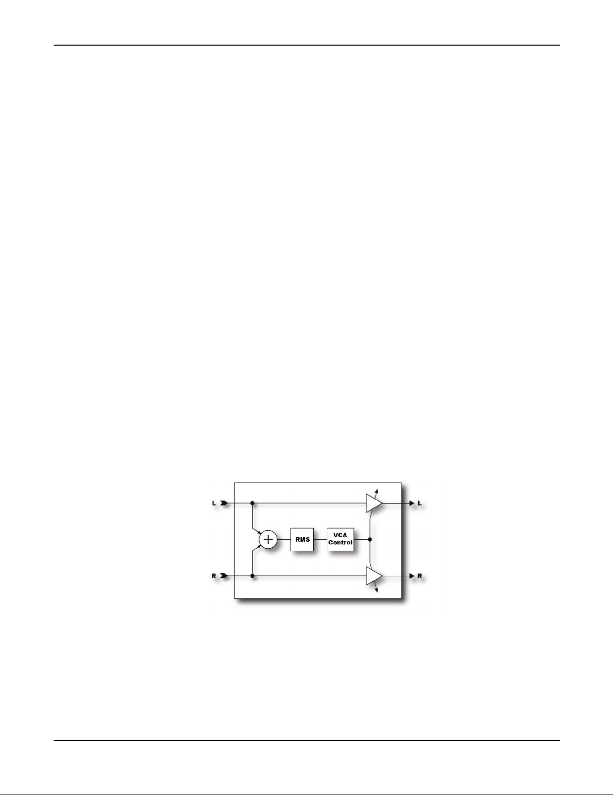
The Compressor reduces the dynamic range of the signal by lowering its gain when the input power
exceeds a threshold. It is best placed at the start of an effects chain and is most effective when used
with clean settings. Using a Compressor with high-gain distortion can lead to excessive noise or
squealing. The Compressor can also be placed near the output of an effects chain if desired to even
out the response if using, say, two different distortion types. The low-gain distortion can be
followed with a Compressor to even out its response compared to a high-gain distortion. Otherwise
the low-gain distortion will be too dynamic.
Page 30

The Effects
Parameters
THRSH -
value.
Threshold control. The Compressor reduces its gain when the input power exceeds this
RATIO -
Sets the gain reduction ratio. This is the ratio of input power to output power beyond the
threshold. For example, if the threshold is -40 dB, the input signal is -30 dB and the ratio is 2.0 the
output will be -35 dB.
ATT -
Attack rate. Sets how fast the Compressor reduces its gain once the threshold is exceeded.
Higher values equal faster response.
REL -
Release rate. Sets how fast the Compressor restores the gain once the signal has fallen below
the threshold.
LEVEL -
KNEE -
Sets the output level of the block. This is the same control as on the
MIX
page.
Sets the "knee" type. A soft knee gradually varies the compression ratio around the
threshold whereas a hard knee switches from no compression to the selected compression ratio
abruptly at the threshold. With high compression ratios a hard knee may produce undesirable
SOFT
artifacts. In this case set the knee type to
MAKEUP -
for easier adjustment. The
DETECT -
Makeup gain. When this is on, the output level is automatically compensated allowing
LEVEL
control can then be used to fine tune the output level.
Selects the type of detector: RMS or peak. RMS detection is smoother, but peak is faster.
.
Experiment with the type that best suits the program material.
Filter
FILTER -
Sets the frequency of a highpass filter on the sidechain input. Raising the frequency can
help prevent low frequencies from “pumping” the entire mix.
SCSEL -
Selects the sidechain input source.
INPUT
is the normal setting and selects the block input
(sum of the rows feeding the block). The other settings allow isolating a single row as the sidechain
input. The other rows are summed as usual. By using a row as the sidechain input you can use the
compressor as a ducker or de-esser.
The Filter module is a simple programmable filter designed for general tone shaping. It allows a
variety of different filters along with real-time control of the filter parameters. You can use the Filter
module for quick, static tone shaping or for elaborate, dynamic tone manipulation.
It can be used as a straight gain block by setting the filter type to NULL. Another possibility is to
use it as a treble booster (with more programmability than the one in the Drive module).
In the 60's guitarists began experimenting with booster pedals to increase the signal level into their
amplifiers. This increased the amount of distortion their amps would produce. The more popular
booster pedals had extra treble boost in addition to overall boost. This technique was essential to
Brian May's tone on the early Queen recordings where a treble booster into a Vox AC-30 gave that
unmistakable sound.
27
Page 31
The Effects
To use the Filter/Boost module as a treble booster set the
Experiment with the
Q
and
FREQ
controls to achieved the desired effect. Increase the level to
TYPE
to either
HIGHPASS
or
BANDPASS
increase the overall signal level out of the block.
The
FREQ, Q, GAIN, LEVEL
parameters select the parameter and press
and
PAN
parameters are all controllable. To attach a modifier to these
ENTER
. This brings up the
MODIFIER
menu. When any
of these parameters are attached to a modifier an asterisk (*) appears after the name indicating such.
Parameters
TYPE -
frequency response characteristic.
FREQ -
ROFFS -
for example, would set the right channel frequency to half the left.
Q-
GAIN -
This control has no effect with the other types.
Sets the type of filter. All the standard filter types are available. A
NULL
type has a flat
Sets the center frequency of the filter.
Sets the right channel frequency offset as a multiple of the left channel. A setting of 0.5,
Sets the ‘Q’ of the filter. Higher values give sharper responses.
Sets the gain at the center frequency for the bandpass, notch, low-shelf and high-shelf types.
.
LEVEL -
PAN -
BYP -
Sets the output volume level of the block.
Sets the output panning of the block.
Sets the bypass mode.
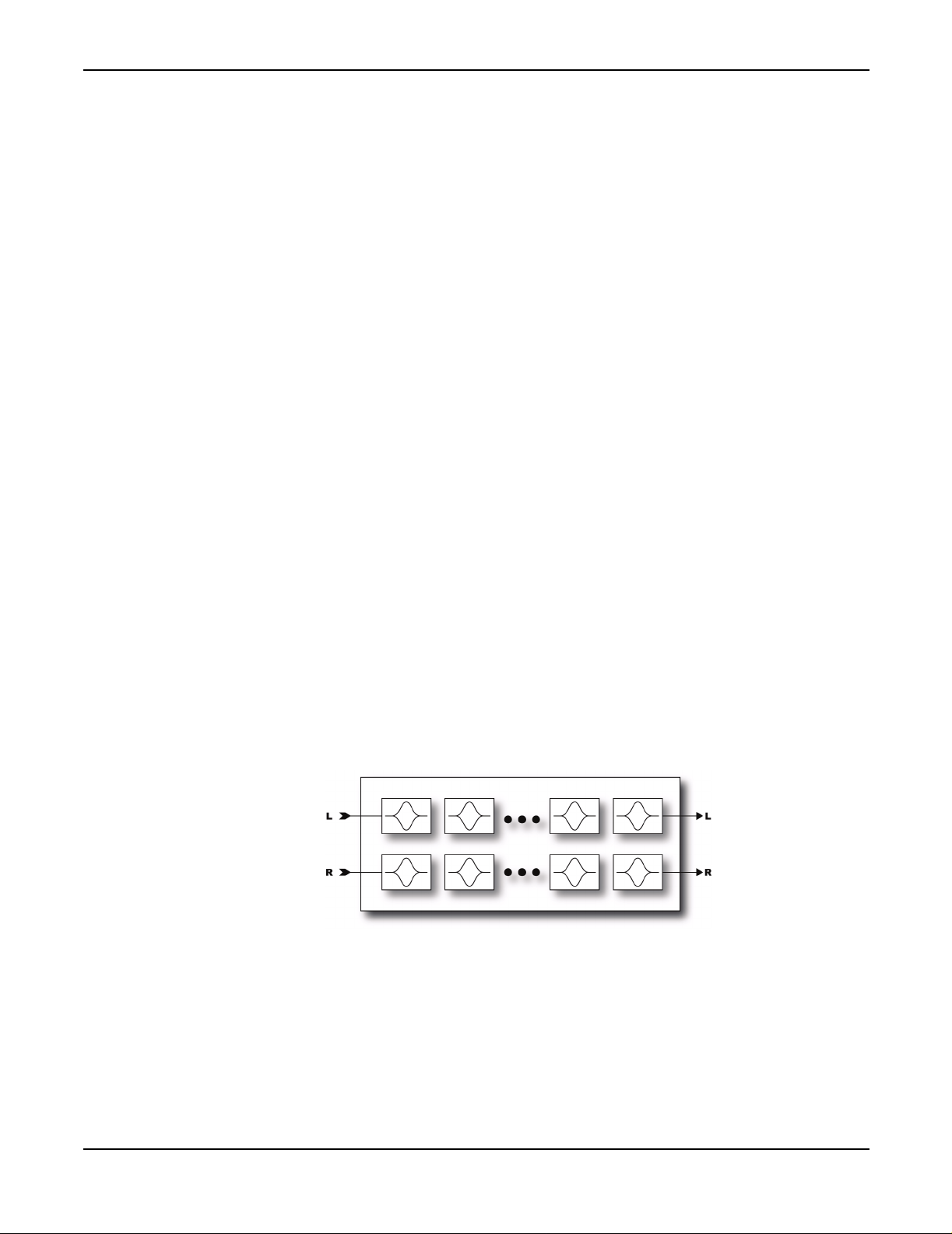
Graphic Equalizer
The Graphic Equalizer is an 8-band equalizer with band centers at 63, 125, 250, 500, 1000, 2000,
4000 and 8000 Hz. Each band can boost or cut up to 12 dB. Simply select the desired band with
navigation buttons and use the value dial to vary the gain.
28
The Graphic EQ can also be used as a booster. To use the EQ as a booster simply emphasize the
desired frequencies and set the level as desired. For a treble booster, for example, one might boost
the 2K, 4K and 8K by 6 dB or so and turn the level up 12 dB. The p arametric equalizers (see below)
can be used in the same way by simply turning up the high-shelf gain and increasing the level.
Page 32
The Effects
Parametric Equalizer
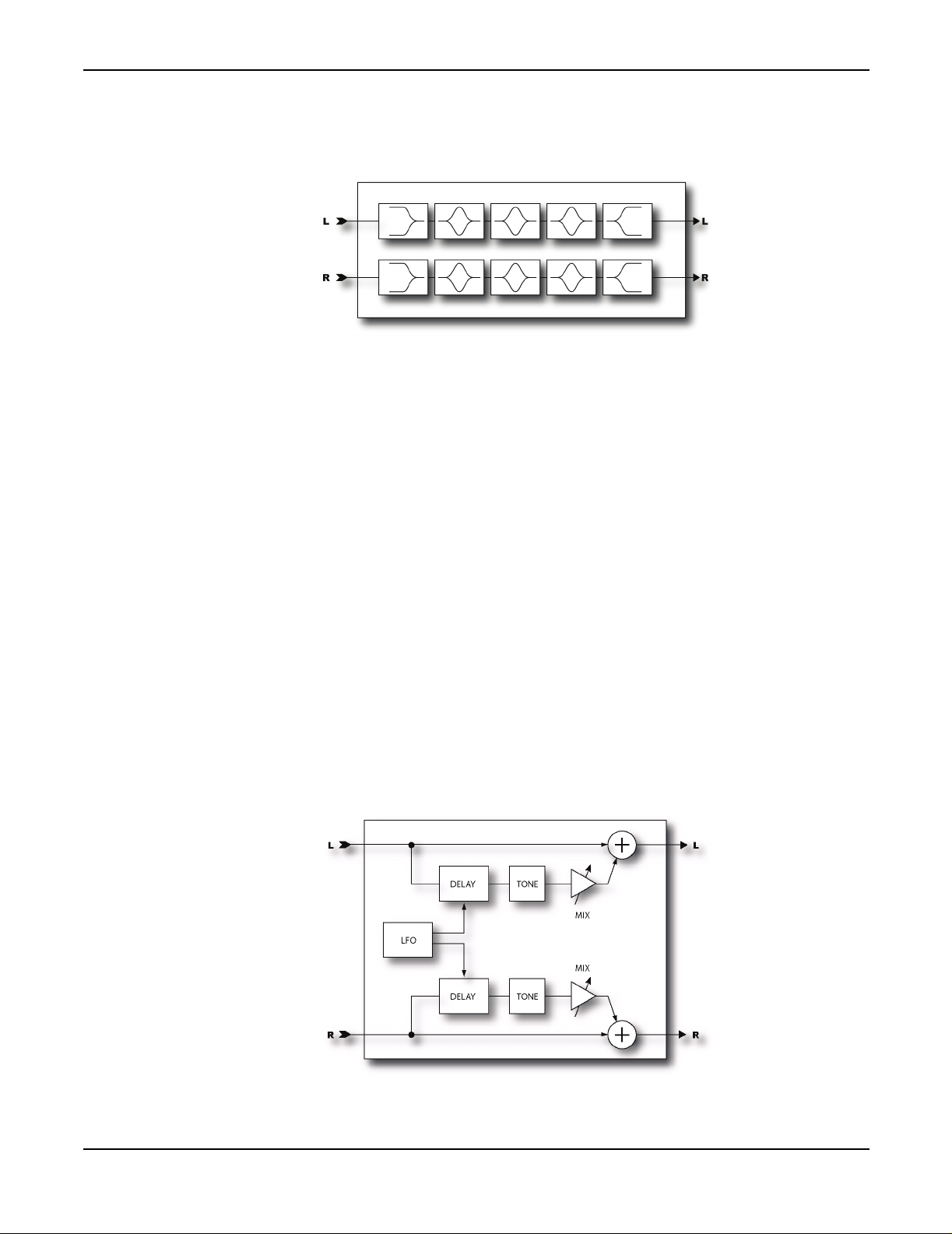
The Parametric Equalizer is a 5-band parametric-type equalizer comprised of a low-shelf filter,
three bell filters and a high-shelf filter. To edit, select the band desired using the
graphical display depicts the response.
Parameters
FREQ -
Sets the center frequency of the band.
PAGE
buttons. A
Chorus
Q-
Sets the "Q" of the band. Q is a measure of filters bandwidth vs. center frequency. Higher Q's
exhibit narrower or sharper response. Use caution as very high values along with high gain can
cause output overload and clipping even though the apparent volume is low. Reduce the block
output level if this occurs.
GAIN -
TYPE - The first and last bands have a selectable filter type. This parameter selects between the
three available types.
Sets the gain of the filter.
29
Page 33

The Effects
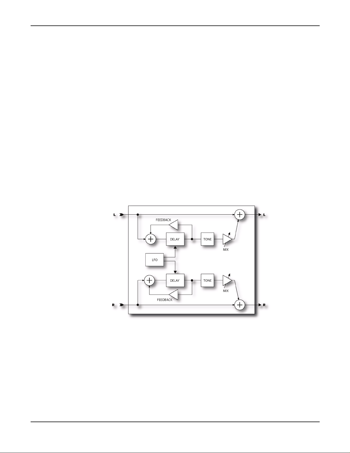
A chorus subtly delays the input signal by a varying amount and mixes it with the undelayed signal.
The varying delay slightly detunes the signal so the result is one of multiple instruments playing in
unison. The Axe-Fx Chorus is a stereo multi-voice chorus. It uses a very computationally
demanding algorithm but delivers exceptionally smooth sounding ensemble effects. Each stereo
channel in the chorus can have from one to four voices. Increasing the number of voices increases
the fullness of the effect. For classic chorus sounds use two voices (one per side). For thick, full
chorus effects use four or more voices.
Basic Parameters
VOICES -
voices per side.
Sets the total number of voices used in the effect. For example, a setting of 4 uses two
RATE -
Controls the frequency of the Low Frequency Oscillator (LFO). Use low settings with
higher depths for slow moving sounds. Increase the rate for vibrato effects. Set fully CCW to sync
the LFO to the Global LFO1 oscillator.
DEPTH -
Sets the maximum delay variation. Higher depths increase the amount of detuning.
Usually the rate and depth settings should be varied inversely, i.e. if you increase the rate decrease
the depth however some unique sounds can be obtained using high rates and depths.
MIX -
Sets the ratio of wet and dry. Duplicated from MIX page. A setting of 50% produces the most
prominent effect. Try setting the mix to 100% for vibrato effects.
TEMPO -
Locks the rate to the global tempo. For example, if the global tempo is 120 bpm and the
tempo is set to a quarter note (1/4) then the LFO rate will be 2 Hz (120 bpm / 60 seconds = 2). To
NONE
ignore the global tempo set the tempo control to
.
Advanced Parameters
BASS -
TREBLE -
BASS FREQ -
Adjusts the bass response of the wet signal. The bass can be boost or cut up to 12 dB.
Adjusts the treble response of the wet signal. The treble can be boost or cut up to 12 dB.
Adjusts the corner frequency of the bass control.
30
TREBLE FREQ -
DELAY TIME -
Adjusts the corner frequency of the treble control.
Adjusts the minimum delay time of the delay line. This can provide subtle changes
in the character of the effect.
LFO PHASE -
Adjusts the phase difference between the left and right lfo waveforms. For maximum
stereo spread set this to 180 degrees. For a mono chorus simply set this to zero.
LFO TYPE -
Selects between sine or triangle waveforms for the LFO. Sine is the most commonly
used waveform.
Page 34
The Effects
Flanger
AUTO DEPTH -
Lower rates therefore increase the actual depth and vice-versa. The
When this is set to
LOW
or
HIGH
the depth is automatically scaled for the rate.
HIGH
setting allows greater
maximum depth. This greatly simplifies adjusting the rate and depth and gives the most musical
results. For wild sounds you may wish to set this to
OFF
which decouples the controls allowing for
full depth swing even at fast rates.
PHASE REVERSE -
When this is set to ON the phase of the right channel is reversed on the effected
signal. This increases the stereo imaging.
WIDTH -
Adjusts the time offset between the left and right delay line. At 100% the right delay line
will be at minimum time, at 0% the right delay time will equal the left. This can be used to increase
the apparent stereo width of the effect.
LFO2 RATE -
Adjusts the rate of the secondary LFO. This LFO modulates the primary LFO and can
be used to create more interesting effects.
LFO2 DEPTH -
Adjusts the depth of the secondary LFO.
31
A flanger is similar to a chorus but uses a shorter delay time and feeds back some of the effect signal
back to the input. It was originally intended to duplicate the sound of two tape decks that were
synchronized together and then pressing on the flange of one of the tape reels (hence the term
flanging). This caused the tape decks to become slightly out of sync and created the classic
wooshing sound. A great example of this is in the Doobie Brother's song "Listen to the Music"
during the bridge.
Basic Parameters
TIME -
Low values give a jet-like sound whereas high values are metallic. Adjust to taste.
Adjusts the nominal delay time of the delay line. This changes the character of the effect.
Page 35

The Effects
RATE -
Controls the frequency of the Low Frequency Oscillator. Use low settings with higher
depths for slow moving sounds. Increase the rate for vibrato effects. Set fully CCW to sync to the
Global LFO1 oscillator.
DEPTH -
Sets the maximum delay variation. Higher depths increase the amount of detuning.
Usually the rate and depth settings should be varied inversely, i.e. if you increase the rate decrease
the depth however some unique sounds can be obtained using high rates and depths.
FEEDBK -
Sets the amount of wet signal fed back to the input. Increasing the feedback can give the
Flanger a metallic quality as it produces sharp resonances in the frequency response. Note that
excessive values can result in marginal stability and may even cause oscillation. Decrease the
feedback if this occurs.
MANUAL -
Manually controls the delay time. You can use this along with a foot controller or other
controller to control the flange effect. For full manual control set the depth to zero.
MIX -
Sets the ratio of wet and dry. Duplicated from MIX page. A setting of 50% produces the most
prominent effect.
TEMPO -
Locks the rate to the global tempo. For example, if the global tempo is 120 bpm and the
tempo is set to a quarter note (1/4) then the LFO rate will be 2 Hz (120 bpm / 60 seconds = 2). To
NONE
ignore the global tempo set the tempo control to
.
Advanced Parameters
BASS -
TREBLE -
BASS FREQ -
TREBLE FREQ -
LFO PHASE -
stereo spread set this to 180 degrees.
LFO TYPE -
can achieve strange rising/falling effects using the sawtooth types.
LFO HICUT -
extreme depth or rate settings, clicking may occur at the waveform discontinuities. For example a
square wave can cause audible artifacts as the LFO rapidly changes from one extreme to the other.
Decreasing the
AUTO DEPTH -
Lower rates therefore increase the actual depth and vice-versa. The
maximum depth. This greatly simplifies adjusting the rate and depth and gives the most musical
results. For wild sounds you may wish to set this to
full depth swing even at fast rates.
Adjusts the bass response of the wet signal. The bass can be boost or cut up to 12 dB.
Adjusts the treble response of the wet signal. The treble can be boost or cut up to 12 dB.
Adjusts the corner frequency of the bass control.
Adjusts the corner frequency of the treble control.
Adjusts the phase difference between the left and right lfo waveforms. For maximum
Selects the waveform for the LFO. Sine is the most commonly used waveform. You
Adjusts the filtering of the LFO waveform. For certain waveform types along with
LFO HICUT
When this is set to
frequency will mitigate this.
LOW
or
HIGH
the depth is automatically scaled for the rate.
OFF
HIGH
setting allows greater
which decouples the controls allowing for
32
Page 36
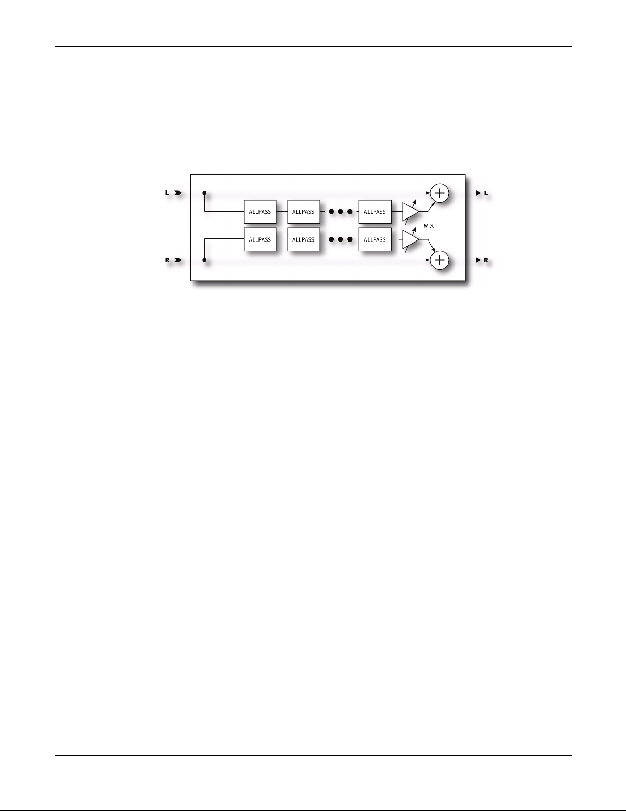
The Effects
Phaser
PHASE REVERSE -
When this is set to ON the phase of the right channel is reversed on the effected
signal. This increases the stereo imaging.
A phaser works by cascading a series of "allpass filters" and then mixing the processed signal with
the input. The allpass filters cause phase shift and at certain frequencies the amount of phase shift
will be exactly out of phase with the input so the mixed signal will have notches at those
frequencies. The Axe-Fx Phaser is extremely powerful allowing from 4 to 12 stages along with a
feedback control for producing even more dramatic effects. Also, the Axe-Fx phase is full stereo
allowing for spatial effects as well.
The Phaser also contains a special “Vibe Mode” that recreates the classic vibe effect with
astonishing accuracy. Set the ORDER control to fully clockwise to activate this mode.
NOTE: The
MIX
control should be set at 50% for the maximum effect.
Basic Parameters
ORDER -
four and use low feedback. For more pronounced effects increase the order. Turning this control
fully clockwise puts the Phaser into “Vibe Mode” where the frequency spacings are fixed. In this
mode the
NOTE: Whenever the order is changed the LFO Type is automatically set to the default. For anything
other than Vibe Mode the LFO Type is set to TRIANGLE. For Vibe Mode the type is set to EXP
(exponential) If you desired a different LFO waveform be sure to check the setting after changing the
order.
RATE -
Global LFO1 oscillator.
DEPTH -
RES -
the resonance increases how sharp the notches are. Excessive values of feedback can cause
instability. If this occurs decrease the feedback.
Sets the number of stages in increments of two. For classic phaser sounds set the order to
FREQ SPAN
control has no effect.
Controls the frequency of the Low Frequency Oscillator. Set fully CCW to sync to the
Controls the sweep depth of the LFO.
Resonance control. Controls how much of the wet signal is fed back to the input. Increasing
33
Page 37
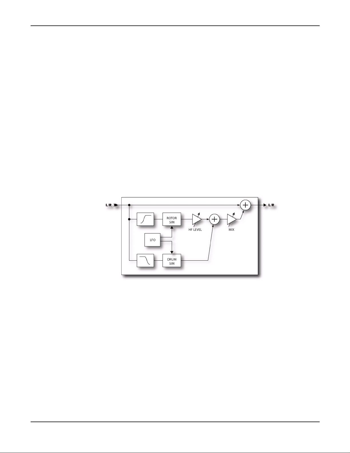
The Effects
FREQ -
Sets the start frequency of the first stage filter. This in combination with the depth control
controls the range over which the notches sweep.
TEMPO -
tempo is set to a quarter note (1/4) then the LFO rate will be 2 Hz (120 bpm / 60 seconds = 2). To
ignore the global tempo set the tempo control to
Advanced Parameters
LFO TYPE -
Experiment with Exponential or Logarithmic types for pulsating effects.
FREQ SPAN -
greater amounts.
LFO PHASE -
Rotary Cabinet
Locks the rate to the global tempo. For example, if the global tempo is 120 bpm and the
NONE
.
Selects the waveform for the LFO. The ramp types can provide falling or rising effects.
Sets the span of the allpass filters. Higher values separate the resulting notches by
Sets the phase difference from left to right for the LFO.
34
A Hammond B3 without a Leslie cabinet is like a BLT sandwich without the lettuce and tomato.
Guitar players soon came to discover the wonderful tones of the Leslie cabinet and it's brethren. The
classic Leslie cabinet is comprised of a spinning drum with a slot in it and a rotating horn called a
rotor. A low frequency speaker is aimed into the spinning drum while high frequencies are sent to
the horn. The result is unmistakable, from schmaltzy hockey-game to Steppenwolf, the Leslie
cabinet became ubiquitous. Spinning drum alone versions have been produced by other
manufacturers with Stevie Ray Vaughn's "Cold Shot" being one example of that sound.
The Axe-Fx Rotary Cabinet simulator reproduces all these classic sounds and offers more control.
Also, it doesn't weigh 300 lbs and require four guys to move up a flight of stairs. Isn't technology
great?
Parameters
RATE -
time control.
Controls the rate at which the "drum and rotor" spin. Connect this to a controller for real-
Page 38
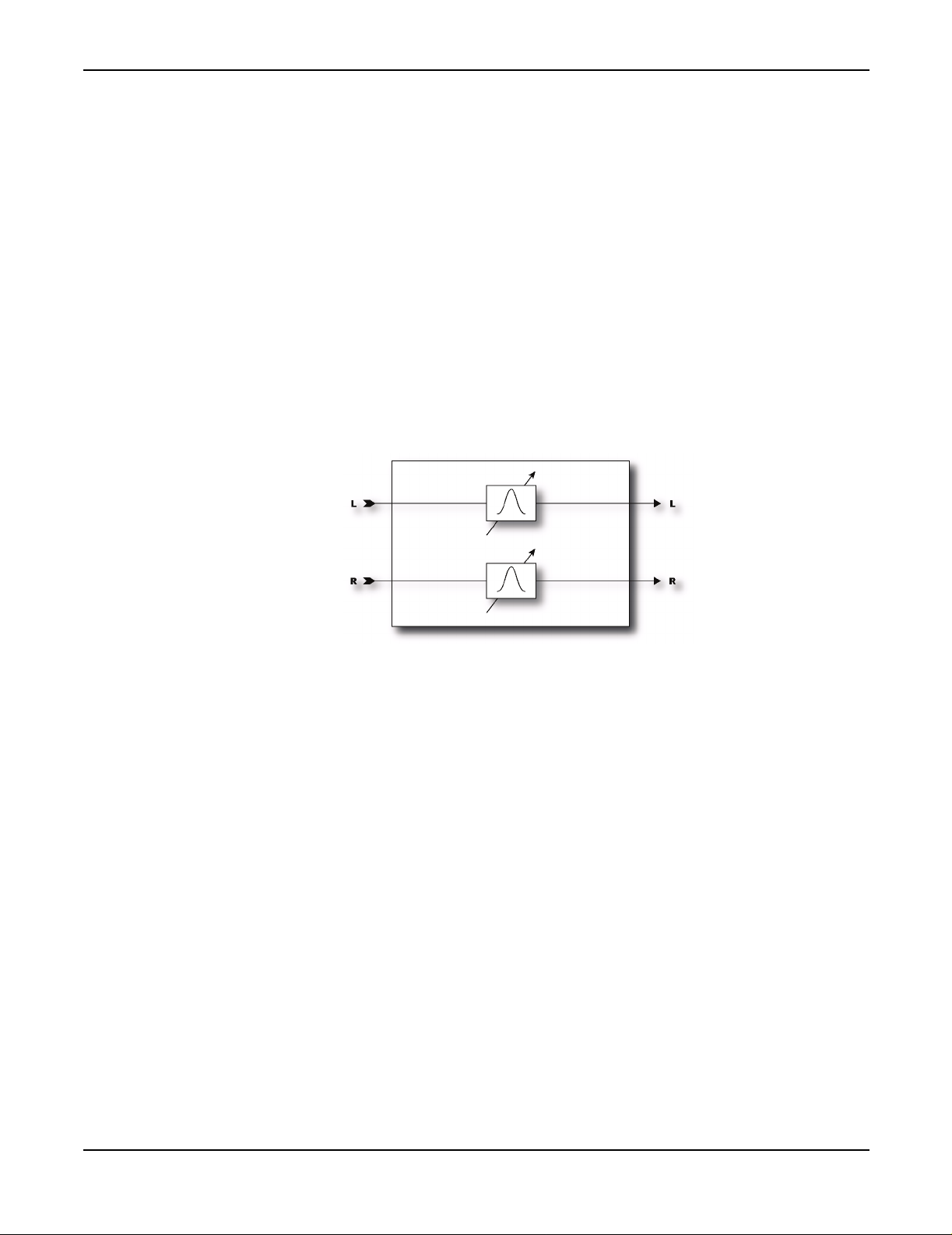
The Effects
LDEPTH -
throb.
HDEPTH -
this.
HLEVEL -
rotor.
TEMPO -
tempo is set to a quarter note (1/4) then the LFO rate will be 2 Hz (120 bpm / 60 seconds = 2). To
ignore the global tempo set the tempo control to
Wah-Wah
Sets the modulation depth of the "drum". Higher settings provide a more pronounced
Sets the modulation depth of the "rotor". To simulate a rotating drum only cabinet reduce
Sets the output level of the "rotor". Use this to balance the level between the drum and
Locks
the rate to the global tempo. For example, if the global tempo is 120 bpm and the
NONE
.
Ah, the legendary wah effect. No effect has ever been as used (or abused). From Jimi Hendrix's
"Voodoo Chile" to, well, Stevie Ray Vaughn's "Voodoo Chile" the wah continues to hold a unique
place in the annals of rock history. The Axe-Fx Wah is the embodiment of this legacy but with
modern reliability and control. Also, the unique control input processing of the Axe-Fx eliminates
the "zipper effect" common to many remotely controlled wahs.
A wah is actually a very straightforward device. The signal is passed through a high-Q filter whose
frequency is controllable. The Wah may be placed before distortion for a subtler, classic sound or
after distortion for a more prominent and aggressive sound.
Parameters
TYPE -
dramatic sound whereas the other filters are more subtle.
FMIN -
adjusted to match the range of your instrument or preference.
FMAX -
RES-
Selects between a lowpass, bandpass or peaking filter. A bandpass filter gives a more
Sets the frequency of the filter when the frequency control is at its lowest value. This can be
Sets the frequency of the filter when the frequency control is at its highest value.
Sets the resonance, or ‘Q’ of the filter. Higher values give a sharper response.
35
Page 39
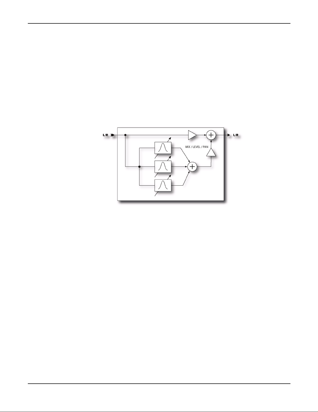
The Effects
TRACK -
decreased by an amount proportional to this value. If this is zero the resonance of the filter will be
constant at all frequencies. Classic wah pedals usually have a resonance that decreases with
frequency due to design limitations. This control can be used to mimic those pedals.
FREQ -
Normally you would attach this to a controller. Attach it to an external controller (such as pedal) for
classic wah or attach it to an LFO or Envelope for autowah or dynamic wah.
Formant Filter
Sets the ‘Q’ tracking of the filter. As the frequency is increased the resonance will be
Sets the frequency of the filter relative to the minimum and maximum frequencies.
The wah was originally intended to mimic the sound of the human voice but obviously falls a little
short. A formant filter is an extension of the wah principle but operates on the concept of formants.
Formants are resonances in instruments, cabinets, and, in this case, the human vocal tract that give
sounds their character. The human vocal tract generates a handful of formants that produce the
vowel sounds we recognize. For example the vowel sound "eee" can be reproduced with a bank of
narrow bandpass filters with various frequencies and amplitudes. The Axe-Fx Formant Filter allows
"talk-box" effects without the fuss and muss of the real thing.
The Format Filter morphs between three vowel sounds: start, mid and end. The
CTRL
knob then
controls the morphing between these sounds. For example, we can program the Formant Filter to
go "ooo - eee - aaahh" as a pedal is moved. The start vowel is generated with the
CTRL
knob counterclockwise, the end vowel is generated with the knob fully clockwise and the mid vowel is generated
with the knob at 12:00. The sound gradually changes from one vowel to the next between positions.
The Formant Filter usually sounds best when placed after distortion although there are no hard and
fast rules.
Parameters
START -
MID -
Sets the start vowel sound.
Sets the mid vowel sound.
36
Page 40
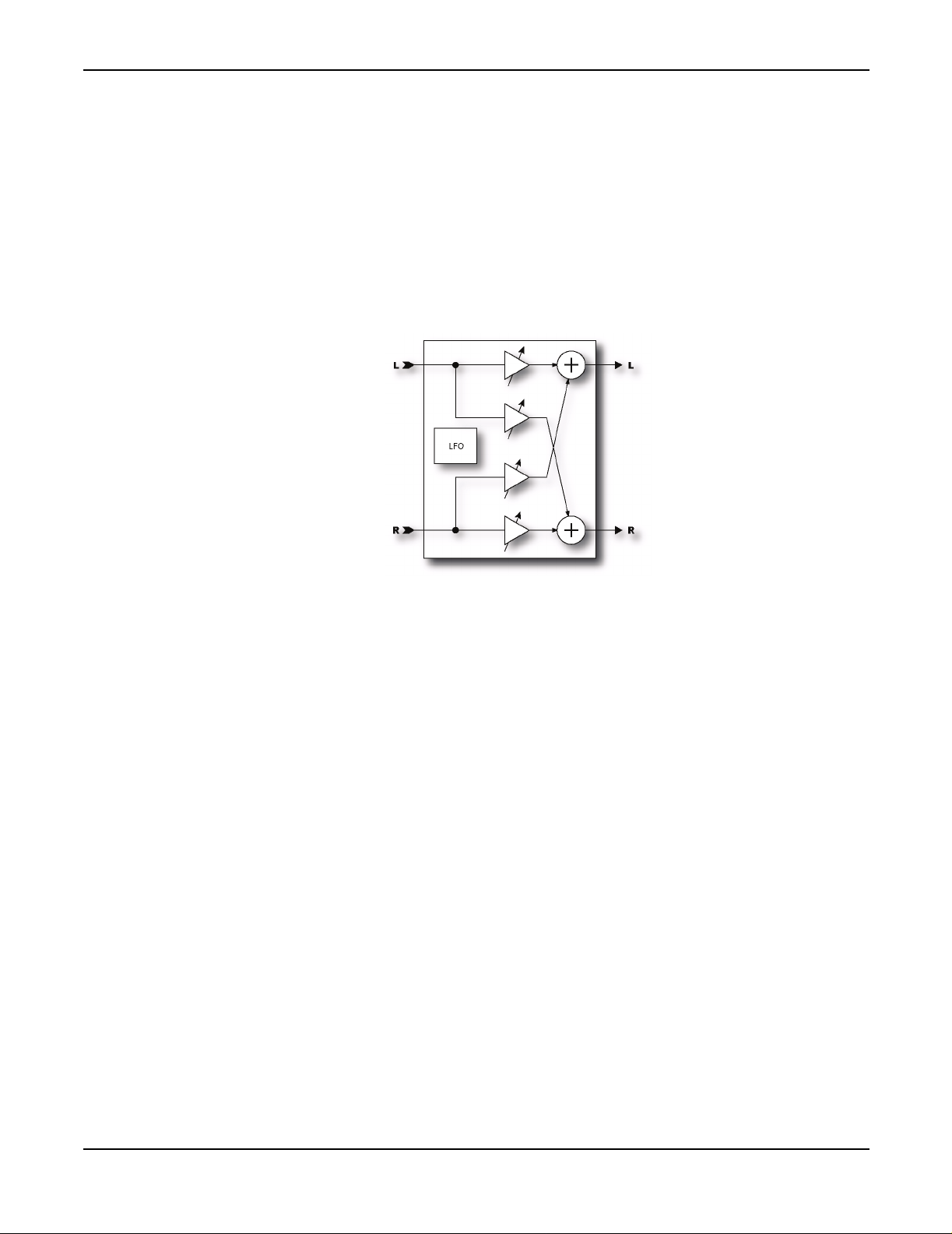
The Effects
END -
RES -
Sets the resonance of the filters. Higher resonance can yield a more dramatic effect.
CTRL -
controller (i.e.
Pan / Tremolo
Sets the end vowel sound.
Controls the morphing between vowel sounds. Normally you would connect this to a
EXTERN1
).
The Axe-Fx Pan/Tremolo provides, as the name would imply, panning and tremolo effects. A
panner moves the sound left/right in the stereo field while a tremolo varies the volume. Tremolo can
be used to get that classic "surf" sound especially when used with some spring reverb.
Parameters
EFF TYPE -
RATE -
LFO1 generator.
DEPTH -
WIDTH -
Panner will pan beyond a normal stereo image
TEMPO -
tempo is set to a quarter note (1/4) then the LFO rate will be 2 Hz (120 bpm / 60 seconds = 2). To
ignore the global tempo set the tempo control to
LFO TYPE -
DUTY -
wave. For a triangle wave this controls the shape of the waveform. At 50% the waveform is
perfectly symmetrical. For a square wave this controls the ratio of time that the waveform is "on"
as opposed to "off". This control has no effect for sine, log, exp or random waveforms
Chooses between the tremolo and panner.
Sets the frequency of the LFO. Turning the control fully CCW locks the rate to the global
Sets the modulation depth for the tremolo.
Sets the modulation depth for the panner. When Width is set to more than 100%, the
Locks the rate to the global tempo. For example, if the global tempo is 120 bpm and the
NONE
.
Selects the waveform for the LFO. Try experimenting with the Log or Exp waveforms.
This controls the symmetry of the LFO waveform. It has no effect if the waveform is a sine
37
Page 41
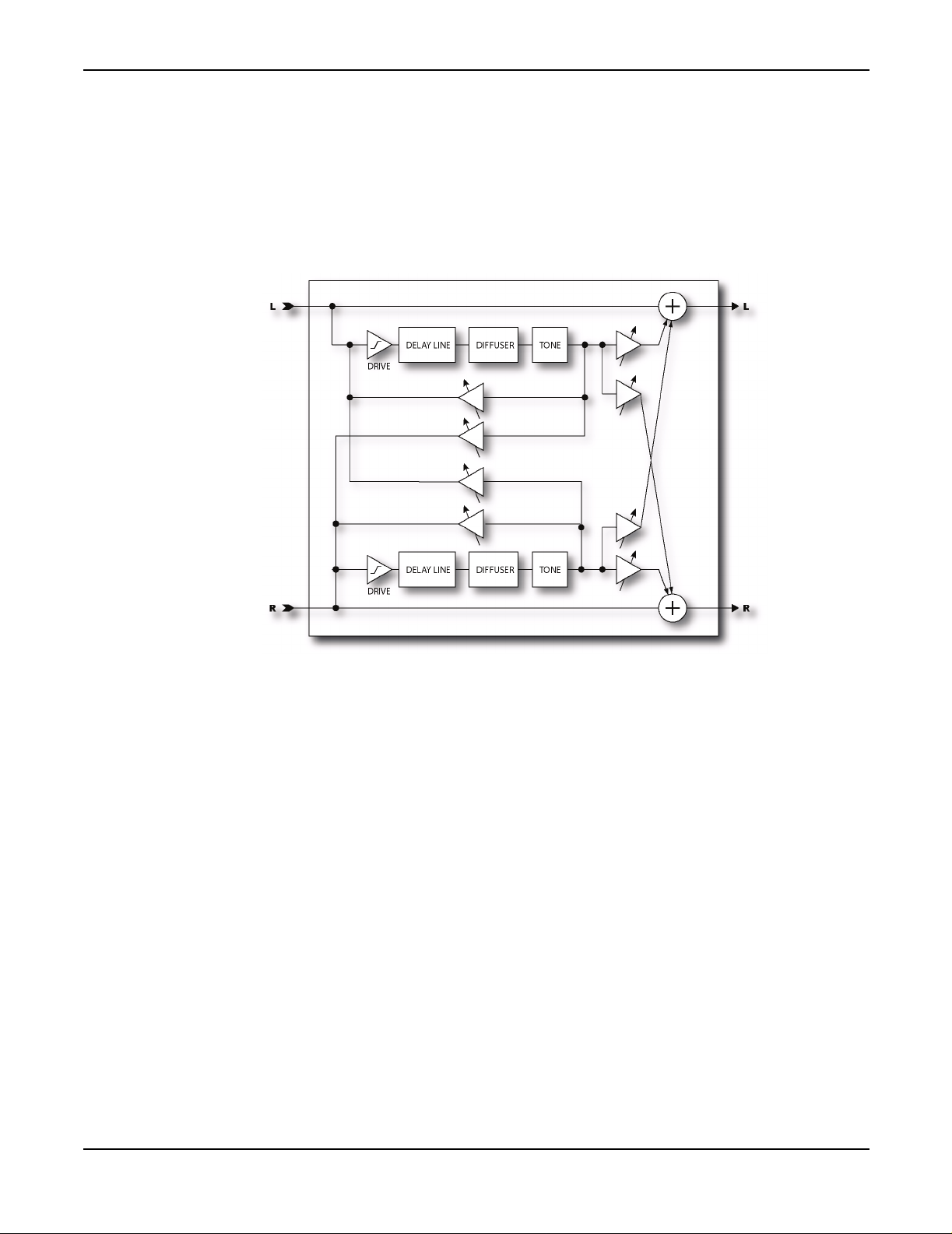
The Effects
Delay
LFO PHASE -
PAN CENTER -
Adjusts the phase difference between the left and right lfo waveforms.
In panner mode adjusts the apparent center of the stereo image.
The real strength of digital processing was first exhibited with the original digital delay processors.
Before that delay processing was done using analog delay devices or tape-based techniques. These
methods suffered from poor frequency response, noise, and in the mechanical versions, reliability
concerns. Digital delays address all of these shortcomings while providing longer delay times.
The Axe-Fx contains two different types of delay blocks. The regular Delay, described here, is your
basic digital delay (with a few enhancements). We'll talk about the Multi-Delay later. The Delay
has five different modes: Mono, Stereo, Ping-Pong, Dual and Reverse. In Mono mode the inputs
are summed and only the left delay line is used. This allows quick, classic delay sounds. The Stereo
mode allows independent left and right delay time and feedback allowing for modern stereo delay
sounds. The Ping-Pong mode criss-crosses the signal so that the echoes ping-pong left and right.
The Dual mode allows full control over the delay block providing controls for all parameters. The
Reverse mode is a special mono reverse looper capable of strange and exotic reverse playback
effects.
The Delay also contains a lowcut and highcut filter to allow frequency response tailoring of the
repeats. By turning down the highcut frequency you can simulate the sound of a tape delay with it's
poor high frequency response. Turning up the lowcut frequency can give a thin delay sound for
special effects.
38
Page 42

The Effects
The Delay also contains two delay time modulators that can be used to slightly modulate the delay
time. These can be used to add depth to the echoes or to simulate an old tape-based echo unit. One
can be used, for example, to simulate the slow fluctuation of a worn belt in a tape echo with the
other simulating a worn capstan (wow and flutter).
The first and third pages of the Delay menu are the same for all types. The second page of the edit
menu changes based on the type of delay selected.
Common Parameters
TYPE -
Selects between the various delay types available.
INGAIN -
Sets the input level into the delay lines. The primary purpose of this is to allow you to
attach a controller (i.e. pedal) to control the delay level without disturbing the mix. Set the mix at
the desired maximum echo level and then use the INLVL control (via a pedal) to control the echo
level. This is different than controlling the echo level with the MIX control since the echoes will
continue to sound after the control is set to zero whereas using the MIX control the echoes will be
immediately cut off. If you are not attaching a controller then you would norm ally set this to 100%
(default).
Mono Delay
TIME - Sets the time of the delay line (time between echoes).
FEEDBK - Sets the amount of delay feedback. This controls how many repeats are heard.
ECHO PAN - Controls the placement of the echoes in the stereo image. Note that this is different
than the PAN control on the MIX page which controls the panning of the mixed sound. This control
only effects the wet signal.
TEMPO - Locks the time to the global tempo. For example, if the global tempo is 120 bpm and the
tempo is set to a quarter note (1/4) then the time will be 500 ms (one echo per beat). To ignore the
global tempo set the tempo control to
LOCUT FREQ - Sets the cutoff frequency of the lowcut filter. Higher values remove more low
frequency content from the delayed signal.
NONE
.
39
HICUT FREQ - Sets the cutoff frequency of the highcut filter. Lower values remove more high
frequency content from the delayed signal.
DRIVE -
Sets the drive level into the tube simulator. This can be used to add some distortion to the
echo like an old tube-based tape delay. This control has no effect when using the Reverse delay
type.
Stereo Delay
TIME - Sets the time of the delay lines (time between echoes).
RATIO - Sets the ratio of the delay time of the right channel relative to the left channel. A ratio of
1.0 sets both channels equal. Decreasing this value decreases the delay time of the right channel.
Page 43

The Effects
SPREAD - Controls the stereo spread of the echoes. Increasing this value increases the separation
between the left and right delay signals.
FEEDBACK L - Sets the amount of delay feedback for the left channel. The left feedback control is
the “master” and will automatically set the right feedback to the proper amount so that both
channels decay at the same rate regardless of the ratio. The right channel feedback control can be
used to override this if desired.
FEEDBACK R - Sets the amount of delay feedback for the right channel.
TEMPO - Locks the left delay time to the global tempo. For example, if the global tempo is 120
bpm and the tempo is set to a quarter note (1/4) then the time will be 500 ms (one echo per beat).
NONE
To ignore the global tempo set the tempo control to
LOCUT FREQ - Sets the cutoff frequency of the lowcut filter. Higher values remove more low
.
frequency content from the delayed signal.
HICUT FREQ - Sets the cutoff frequency of the highcut filter. Lower values remove more high
frequency content from the delayed signal.
DRIVE -
Sets the drive level into the tube simulator. This can be used to add some distortion to the
echo like an old tube-based tape delay. This control has no effect when using the Reverse delay
type.
Ping-Pong Delay
TIME - Sets the time of the delay lines (time between echoes).
FEEDBK - Sets the amount of delay feedback. This controls how many repeats are heard.
SPREAD - Controls the stereo spread of the echoes. Increasing this value increases the separation
between the left and right delay signals.
TEMPO - Locks the delay time to the global tempo. For example, if the global tempo is 120 bpm
and the tempo is set to a quarter note (1/4) then the time will be 500 ms (one echo per beat). To
ignore the global tempo set the tempo control to
LOCUT FREQ - Sets the cutoff frequency of the lowcut filter. Higher values remove more low
frequency content from the delayed signal.
HICUT FREQ - Sets the cutoff frequency of the highcut filter. Lower values remove more high
frequency content from the delayed signal.
NONE
.
40
DRIVE -
Sets the drive level into the tube simulator. This can be used to add some distortion to the
echo like an old tube-based tape delay. This control has no effect when using the Reverse delay
type.
Dual Delay
TIME L - Sets the time of the left delay line.
Page 44

The Effects
TIME R - Sets the time of the right delay line.
TEMPO L/R - Locks the delay time to the global tempo. For example, if the global tempo is 120
bpm and the tempo is set to a quarter note (1/4) then the time will be 500 ms (one echo per beat).
To ignore the global tempo set the tempo control to
FEEDBK L->L/R-.R - Sets the amount of delay feedback for the delay line. This controls how many
NONE
.
repeats are heard.
FEEDBK L->R/R-.L - Sets the amount of cross feedback for the delay lines. This controls how much
of the left delay line is fed back to the right and vice-versa.
LEVEL L/R - Sets the volume level of the delayed signals.
PAN L/R - Controls the panning of the delayed signals.
LOCUT FREQ - Sets the cutoff frequency of the lowcut filter. Higher values remove more low
frequency content from the delayed signal.
HICUT FREQ - Sets the cutoff frequency of the highcut filter. Lower values remove more high
frequency content from the delayed signal.
DRIVE -
Sets the drive level into the tube simulator. This can be used to add some distortion to the
echo like an old tube-based tape delay. This control has no effect when using the Reverse delay
type.
Reverse Delay
TIME - Sets the time of the delay line (time between echoes).
FEEDBK - Sets the amount of delay feedback. This controls how many repeats are heard. Use
caution as instability can occur with the reverse type with certain parameter settings.
ECHO PAN - Controls the placement of the echoes in the stereo image. Note that this is different
than the PAN control on the MIX page which controls the panning of the mixed sound. This control
only effects the wet signal.
RUN - When this is set to ON the reverse playback is active. You can start and stop playback using
this or by attaching a controller to it.
TRIG RESTART - When this is set to ON the reverse playback restarts when triggered via the RUN
control. If set to
TEMPO - Locks the time to the global tempo. For example, if the global tempo is 120 bpm and the
tempo is set to a quarter note (1/4) then the time will be 500 ms (one echo per beat). To ignore the
global tempo set the tempo control to
OFF, the playback continues from the current position.
NONE
.
41
Page 45

The Effects
XFADE TIME - Sets the crossfade time between reverse audio snippets. When the playback position
approaches the delay time a new snippet begins playback at time zero. The crossfade time controls
how long it takes for the old snippet to fade out and the new one to fade in. You can achieve
interesting and rhythmic variations by setting a long crossfade time. For classic reverse delay
sounds set this at or near its minimum value.
LOCUT FREQ - Sets the cutoff frequency of the lowcut filter. Higher values remove more low
frequency content from the delayed signal.
HICUT FREQ - Sets the cutoff frequency of the highcut filter. Lower values remove more high
frequency content from the delayed signal.
Modulation
The
MOD
page contains the various dynamic parameters that can be adjusted.
LFO1/2 TYPE -
LFO1/2 TARGET -
Sets the type of LFO for the delay time modulators.
Sets which delay line(s) the LFO will modulate. You can select to modulate left,
right or both.
LFO1/2 RATE -
Sets the rate of the time modulators. The delay time can be modulated so as to
simulate a worn capstan or belt or to add a chorus effect to the echoes.
LFO1/2 DEPTH -
DEPTH RANGE -
and vice-versa. The
DUCKER -
Sets the depth of the time modulators. Use in conjunction with the rate controls.
The modulators use “auto depth”, faster rates automatically decrease the depth
DEPTH RANGE control allows selecting the amount of maximum depth.
Turns the delay ducking on or off. Ducking reduces the volume of the delayed signal in
response to your playing. The volume of the echoes then increases when you stop playing.
ATTENUATION -
Sets the attenuation depth of the ducker. A setting of 20 dB, for example, will
decrease the echoes by 20 dB when the input level is above the threshold.
THRESHOLD -
delayed signal will be attenuated by an amount equal to that set with the
RELEASE TIME -
Sets the trigger threshold of the ducker. If the input signal exceeds this value the
ATTENUATION control.
Sets the rate at which the ducker releases the attenuation when the input signal
falls below the threshold.
PHASE REV -
stereo effect.
Multi Delay
The Multi-Delay is a rhythmic delay block with five sub-algorithms: Quadtap delay, Plex Delay,
Plex Detune, Plex Shift and Band Delay. Delay times can be controlled by tempo allowing for
rhythmic patterns to be easily created.
42
When set to ON, inverts the phase of the right channel. This can be used to widen the
Page 46
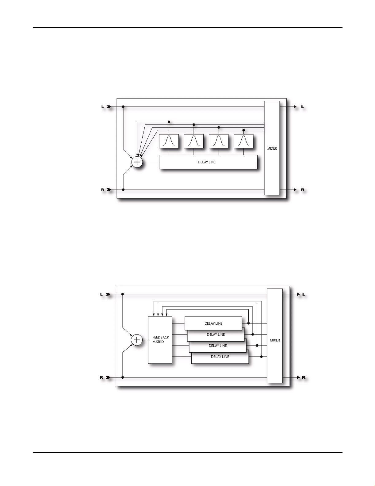
The Effects
The following diagrams illustrate the various algorithms. Parameters vary by type but are listed
together for ease of reference.
QuadTap Delay
Plex Delay / Plex Detune / Plex Shift
43
Page 47
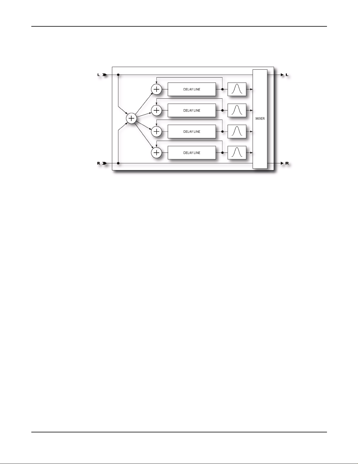
The Effects
Band Delay
Parameters
MASTER TIME -
delay times.
MASTER LEVEL -
echo levels.
MASTER PAN -
go negative allowing for the echoes to switch sides. Attach a controller to this for real-time control
of the pans.
MASTER FEEDBACK -
MASTER FREQ -
values in real-time. This can be used to achieve a wah-like effect on the echoes.
MASTER Q -
MASTER DETUNE -
values in real-time. By varying the detune values this way, resonances are broken up and the delay
becomes smoother.
MASTER PITCH -
real-time.
Scales all the delay times. Attach a controller to this for real-time control of the
Scales all the output levels. Attach a controller to this for real-time control of the
Scales all the pan amounts essentially acting as a spread control. The amount can
Scales all the feedback amounts. You can attach a controller to this.
Scales all the frequency values. Attach a controller to this to vary all the frequency
Scales all the Q values. Attach a controller to this to vary all the Q values in real-time.
Scales all the detune values. Attach a controller to this to scale all the detune
Scales all the shift values. Attach a controller to this to vary all the pitch shifts in
44
DECAY TIME -
Sets the coefficients of the feedback matrix for the Plex types thereby controlling the
amount of time for the echoes to fade. Use caution with the Detune and Shift types as high decay
times can result in instability.
DIFFUSION -
Sets the amount of cross-coupling between delay lines.
Page 48

The Effects
TIME -
TEMPO -
Sets the delay time of the tap.
Locks the delay time to the global tempo. For example, if the global tempo is 120 bpm
and the tempo is set to a quarter note (1/4) then the time will be 500 ms (one echo per beat). To
ignore the global tempo set the tempo control to
LEVEL -
FEEDBACK -
Sets the volume level of the tap.
Sets the amount of delay feedback. This controls how many repeats are heard. The
NONE
.
total of all feedbacks must add up to 100% or less.
PAN -
Controls the placement of the echoes in the stereo image. Note that this is different than the
PAN control on the MIX page which controls the panning of the mixed sound. This control only
effects the wet signal.
DETUNE -
Sets the amount of pitch detune for the delay line for the Plex Detune and Plex Shift
types.
SPLICE LEN -
DIRECTION -
CROSSFADE - Sets the amount of overlap in the audio snippets. A low setting will make the echoes
Sets the splice time for the detuners. Longer times are smoother but less precise.
Sets direction of the pitch shifter. Reverse can be used for atmospheric textures.
more discrete whereas a high setting will tend to smear the echoes.
SHIFT -
FREQ -
Q-
Sets the amount of pitch shift for the delay line for the Plex Shift type.
Sets the center frequency of the delay line output filter.
Sets the ‘Q’ of the delay line output filter. Higher values result in narrower bandwidth. The
Axe-Fx uses a constant power algorithm so higher Q’s increase the gain of the filter. As such, use
caution as overloads could result with some program material.
LFO RATE -
Controls the frequency of the Low Frequency Oscillator (LFO). Use low settings with
higher depths for slow moving sounds. Increase the rate for vibrato effects. Set fully CCW to sync
the LFO to the Global LFO1 oscillator.
LFO TEMPO -
Locks the rate to the global tempo. For example, if the global tempo is 120 bpm and
the tempo is set to a quarter note (1/4) then the LFO rate will be 2 Hz (120 bpm / 60 seconds = 2).
NONE
To ignore the global tempo set the tempo control to
LFO DEPTH -
Sets the maximum delay variation. Higher depths increase the amount of detuning.
.
Usually the rate and depth settings should be varied inversely, i.e. if you increase the rate decrease
the depth however some unique sounds can be obtained using high rates and depths.
45
Page 49
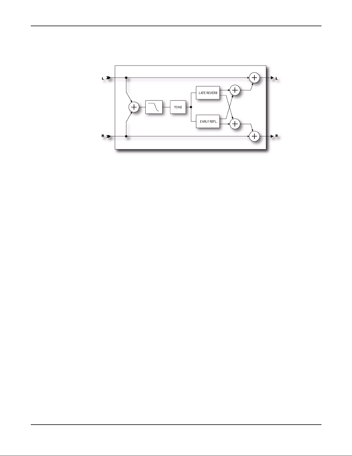
The Effects
Reverb
Aside from distortion no effect is probably more important to the electric guitar than reverb. From
almost the instant that amplifiers were created, guitarists yearned to be able to duplicate the sound
of their amps in a hall or large room. Early reverb simulators incorporated springs or large metal
plates. Most fine recording studios had their own large rooms de dicated to providing reverb. A
speaker and microphone were placed in the room and the reverberated sound was recorded.
Digital processing excels at simulating reverberation and the Axe-Fx has one of the finest reverbs
you've likely heard. A proprietary bandpass comb-filter algorithm provides extremely dense and
smooth reverbs with no graininess or metallic qualities. The Axe-Fx provides six basic reverb types:
Room, Hall, Chamber, Plate, Spring, and Vintage.
The Room reverb type simulates an actual room. It is the type to use when you want the most
natural, realistic reverb. Also great on vocals and percussion.
The Hall reverb type is similar to the Room reverb but simulates a concert hall. It is a little less
smooth and has some response peaks lending it a unique character. Use this when you want your
sound to stand out a little.
The Chamber reverb type simulates the sound of large, boxy chamber. It is useful when you want
a bright, resonant reverb sound.
The Plate type simulates the sound of a vintage reverb plate. These are large metal plates suspended
in a frame. An acoustic signal is launched into the plate and pickups record the sound that is
produced as it bounces around inside the metal. Plate reverbs are characterized by their smooth yet
bright sound and were popular in the 70's and 80's especially for vocals. The Axe-Fx Plate
simulation captures the "shiny" sound of a plate reverb but without all the complicated setup.
The Spring reverb type is an algorithm that has the smoothness of a real spring reverb but without
the “boinginess”. It’s a type all its own and works great for clean or slightly dirty rhythm sounds
when you want the vintage vibe without that overly springy quality.
46
Page 50

The Effects
The Vintage reverb simulates the sound of the old spring reverbs used in popular guitar amplifiers
(except for the crashing sound when someone trips over it). It uses a completely different algorithm
than the other reverb types and accurately replicates a real spring reverb complete with the spring
“chirp”. It is characterized by a pronounced midrange voice with a slightly "boingy" quality. For
surf and rockabilly dial up the Spring reverb, plug in your Strat or Tele and lay down some Dick
Dale.
The Axe-Fx Reverb edit menu has three pages. The basic page has the most commonly used of the
parameters below. The mix page is the standard mixer. The advanced page allows for more in-depth
editing and contains all the adjustable parameters (except for the mixer parameters).
Parameters
TYPE -
medium, and large. Each type sets the parameters below to a preset value. You can override the
parameter values afterward but if you then change the type the values will be reset to the default
values for that type.
Selects the reverb type. The are six basic types with three variations for each type, small,
TIME -
Sets the reverb decay time. This is the amount of time for the reverb to vanish beyond the
point of perception. This is known as the t60 time, referring to the amount of time required for the
reverb to decay to 0.001 of its initial value (-60 dB).
SIZE -
Sets the size of the spring, room, hall etc. This controls the length of time it takes for an echo
to bounce between the walls. Increasing this increases the echo time and also increases the delay
before the reverb starts. Small values smooth out the reverb, very small values can be used to obtain
a metallic sound. Large values can make the reverb more grainy as the time between the individual
repeats increases. Also, as the size is increased the reverb will become somewhat darker as the high
frequencies are absorbed more.
This control is important in that it actually sets the size of the room, hall, etc. that is simulated by
the algorithm. If you want the reverb to sound like a huge concert hall then best results will be
obtained by increasing this value. Of course there are no rules and you can set the size small and the
time high to obtain some interesting effects.
INLVL -
Sets input level to the reverb. Primarily for use with a controller to control the reverb and
allow the reverb to continue to sound. Set to 100% normally. Attach a controller to vary the reverb
level without disturbing the mix.
LOCUT -
HICUT -
Decreases the low-frequency content of the wet signal
Decreases the high-frequency content of the wet signal
47
COLOR -
Sets the color of the reverb. Higher values simulate less high-frequency wall absorption
and result in a brighter reverb.
DIFFUSION -
Controls the density of the reverb tail. Higher values give a smoother sound. Lower
values allow the individual repeats to be more easily discerned.
Page 51
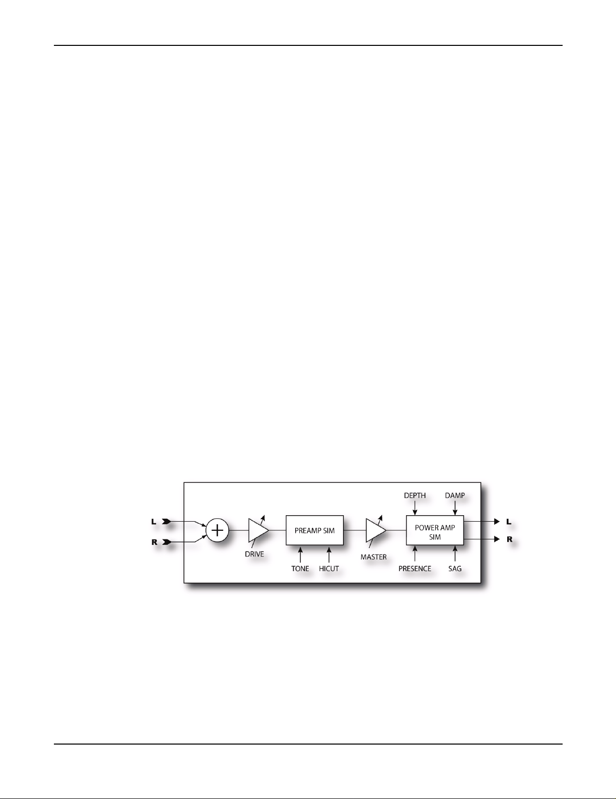
The Effects
PRE DELAY -
Adds extra delay before the reverb starts. The
SIZE
control automatically imparts a
certain amount of delay before the reverb starts. Use this control to add more delay if desired. For
example, if the SIZE is low the reverb will start almost immediately. You can use this control to add
some delay before the reverb starts but keep the small sounding size.
EARLY DELAY -
This controls the relationship between the early reflections and the reverb tail. This
allows a +/- 50% change in the early reflections initial delay. The size control automatically sets the
time between the early reflections and the tail. You can use this control to vary that time.
EARLY LEVEL -
Adjusts the relative volume level of the early reflections. This control has no effect
for the Spring reverb type.
REVERB LEVEL -
MOD DEPTH -
musical sound experiment with this and the
Adjusts the relative volume level of the reverb tail.
This parameter controls the depth of modulation of the reverb tail. For a more
MOD RATE
control. The reverb contains an LFO that
modulates the delay lines that comprise the reverb. This modulation helps fill out the soundstage
and makes the reverb sound fuller. The modulation is best used on pitched instruments. For
percussive instruments (i.e. drums) it may sound better with the modulation off. Set the depth to
zero to defeat the modulation. To hear the effect of the modulation turn the mix to max and adjust
the depth and rate, then set the mix to the desired amount.
NOTE: The modulation depth defaults to zero. To use the modulation you must enter the advanced
parameter page and set the depth and rate as desired.
MOD RATE -
Amp Simulator
Without distortion the electric guitar probably wouldn't have had nearly the impact it has had on
popular music. The Axe-Fx contains multiple distortions based on emulations of various amplif iers.
As mentioned earlier the Axe-Fx is not a modeler however these emulations provide sonic
characteristics very similar to the amplifier they are emulating.
One of the primary differences between the Axe-Fx and a modeling amplifier is the control
philosophy. Modeling amps replicate the operation of the tone, volume, drive, etc. controls even
replicating the annoying interaction among these controls. The Axe-Fx philosophy is to provide the
This parameter controls the rate of modulation of the reverb tail.
48
Page 52

The Effects
control as a more useful tool rather than a strict replica of the original. In this regard the tone
controls on the Axe-Fx are true cut/boost equalizing controls and do not interact. Because of this
the controls are more powerful and are set differently than on a typical amplifier. "Diming" all the
tone controls may sound great on an old tube amp but usually gives less the optimum results with
the Axe-Fx.
The Axe-Fx distortion is based on a proprietary dual-stage non-linearity generator. There are two
basic stages: preamplifier and power amplifier. The preamplifier stage emulates the distortion
generated by classic tube preamplifiers. The power amplifier stage emulates the type of distortion
generated by a tube power amplifier using our proprietary Dynamic Response Technology™.
Full control over all parameters is naturally afforded allowing precise tailoring of this all-important
block to your particular sonic tastes. Read the following carefully as the distortion block in the AxeFx is very sophisticated and a complete understanding will allow you to get the most from it. Also
it is important to understand the role of the Cabinet Simulator in the overall sound. The cabinet
contributes to the sound of a preset at least as much the amplifier type. If you’re not getting the exact
sound you’re looking for try a different cabinet simulation. Of course there are no “rules” so there’s
nothing preventing you from using a 10” blues cabinet with a high-gain amp simulation.
Experimentation can lead to some unique and useful sounds.
Parameters
GLBL -
assigning up to ten “global amplifiers” that are stored in non-volatile memory. Whenever a global
amplifier is selected the parameters for the amp block are loaded from memory. If a parameter is
changed and the preset is then stored, the parameters are written back to memory. Any other presets
that then use the same global amplifier will reflect those changes.
You can use this to store your most used amp types. For example, if you use, say, Plexi for most of
your crunch rhythm presets you can select Global Amplifier 1 and then set the type to Plexi. Dial
in your tone and save the preset. Now in any other preset you want to use those settings simply set
the Global Amplifier to ‘1’. If you find you want a little more treble you can turn the treble up and
all presets that use Global Amp 1 will now reflect that change. It’s like having a 10-channel MIDI
preamp built in.
TYPE -
well as some hybrids and completely original types that we concocted. The following types are
available:
The Global Amplifier selector is a Fractal Audio exclusive. This unique parameter allows
Selects the amplifier simulation. The simulations are based on classic and modern amps as
•
Tube Pre
- A completely neutral, low-gain tube pre-amp simulation. Useful for warming up
vocals and other instruments.
•
Jazz
- Based on a Japanese solid-state amp with built-in chorus. With essentially no tone
shaping this amp has a warm, midrange-thick sound that is good for jazz and fingerstyle. With
the Axe-Fx’s powerful tone controls you can tweak this type to get shimmering rhythm tones
as well.
49
•
Brownface
- Based on a classic American 40-watt tube amp with built-in vibrato. Great for
gutsy blues, this type breaks up nicely, especially when the Master is cranked. The original had
no Mid or Presence so set these to ‘0’ for classic tone.
Page 53

The Effects
•
Blues
- A low-to-medium gain sound great for blues. Based on a classic bass amplifier with
four 10” speakers, it didn’t work so well for bass but guitar players quickly discovered it made
a great blues amp. Try a treble booster in front for screaming blues work a la Albert Collins or
Albert King.
•
Tweed
- Based on a small, low-power, tweed-covered amp. The original had no controls othe r
than volume. Set all tone controls to ‘0’ for authentic tone. Adjust as desired to venture into new
sonic territory. Our simulation has a bit more gain than the somewhat anemic original to allow
you to dial in a nice crunch. To recreate the original faithfully set the drive to about 6 and use
the Master as the volume.
•
Blackface
simulation captures the Normal Channel. Very similar to the Brownface model but a little more
mellow. The tone-stack is also slightly different giving it just a bit different voicing.
•
Class A
not have the high-frequency emphasis like the American types and therefore has a darker sound.
Try a treble boost in front for a snarling British “opera-rock” sound. This amp is notable in that
it has no negative feedback around the power-amp and hence has a gritty character and less
high-frequency response.
•
Top Boost
brighter amp and the designers responded by adding a treble boost circuit. At first this circuit
was a retrofit but then included as standard. Our simulation captures the boosted high-frequency
response and slightly reduced bass response of the original.
- Based on a popular, 100-watt American tube amp with two 12” speakers. This
- A medium-gain emulation based on an early British tube amplifier. This type does
- Based on the “Top Boost Mod” version of the Class A. The public yearned for a
•
Plexi
- Based on a classic British amp, the Plexi is great for crunchy rhythm work. The original
was basically a copy of the 4x10 bass amp (see Blues type above) that guitar players adopted
but with EL34 output tubes and other British components. Despite being essentially a copy it
had a unique voice all its own. It has somewhat low preamp gain and works best with the Master
and Drive both set fairly high.
•
Brit 800
80’s rock hits were born using this amp and we’ve captured its tone and put it into a neat little
package. This amp had EL34 output tubes, some treble peaking on the input and a little more
gain than the Plexi. Like the Plexi type it likes having the Master cranked. At low Master
settings the amp can be brittle but bring the Master up and the true tone of this beast comes out.
Try it with any of the 4x12 cabinet types for classic rock and metal tones. Try a drive block in
front for more snarl.
•
Brit 900
power amp but a new preamp with more tone shaping, more gain, and a solid-state clipping
circuit that gave it a raspier sound. This amp was designed to get more of it’s distortion from
the preamp than the earlier models but you can still keep the drive low and turn up the Master
for more power amp distortion.
•
Brown
This type captures the sound of Eddie’s early work. Crank the Master and bring the drive up
until you reach sonic nirvana.
•
Boutique 1
Based on a now-defunct amplifier that was renowned for it’s liquid tone and endless sustain.
This amp had very unique tone controls and as a result a distinctive voice with a bell-like
quality. The preamp gain is fairly low so crank the Master to get that gutsy crunch. Good for
rhythm work in a sparse situation where fullness of tone is required.
- The successor to the Plexi type was the vaunted 800 series lead amplifier. Many
- The successor to the 800 series was the 900 series. This amp had basically the same
- Based on a modified British style head with plenty of gain and lots of mids and highs.
- A medium-gain, thick, yet crisp, sound with a fair amount of power amp breakup.
50
•
Boutique 2
The lead version of Boutique 1.
- Same as Boutique 1 but with more gain and a bit more high-frequency emphasis.
Page 54

The Effects
•
HiPower I
had a unique tone-stack and industrial quality output transformers with tremendous freq uency
response. Chimey with a bit of power amp breakup. Plug in your Tele and crank out some Baba
O'Reilly.
•
HiPower II
•
USA Clean
a classic California amp’s clean channel this type has a full tone with a gentle midrange dip.
The power amp is punchy and clean but can be driven into light distortio n if desired. Sounds
best with the drive turned up fairly high.
•
USA Rhy 1
up.
•
USA Rhy 2
removes the midrange dip from the tone stack and gives a more focused sound and a bit more
gain.
•
USA Lead 1
modern Californian lead amp that set the standard for hi-gain lead tones. With the tone-stack
before the preamp tubes this type has a more liquid response than the British types where the
tone-stack is after the preamp. For the classic California lead sound turn the drive up and back
of the Master a bit so that most of the distortion is coming from the preamp.
- A medium-gain, full sound based on a famous “High Wattage” amp. These amps
- Like HiPower I but using the “Brilliant” channel.
- A somewhat neutral clean sound that can pushed into gentle clipping. Based on
- Crunchy California rhythm sound. Effective for solo use too with the gain turned
- Similar to USA Rhy 1 but with the “mid-boost” engaged. This effectively
- A tight, focused, hi-gain sound great for fusion and rock leads. Based on a
•
USA Lead 2
response of the treble control lower and gives a slightly different character to the tone. There is
also a “treble peaker” on the input stage which slightly boosts the high frequencies giving this
type a little more “cut”.
•
Recto 1
type is characterized by a big bottom and some top-end sizzle. The tone-stack location is after
the preamp which is quite a departure from the earlier Californian amplifiers.
•
Recto 2
•
Solo 100
snarling lead sound. Also great for aggressive rhythm work, this type “chugs” nicely without
getting muddy. Pair it with one of the 4x12 cabinet simulations for modern rock tones.
•
Spec. OD 1
and others. Another amp with a very strange tone-stack, this amp has a singing voice and is
great for modern blues/fusion work. This is the clean channel.
•
Spec. OD 2
•
Euro 1
with lots more gain and more high-frequency emphasis. This type simulates the overdrive
channel with the boost and “structure” switches off.
•
Euro 2
plenty of low-end chunk along with a crispy top-end. Great for modern metal.
- Similar to USA Lead I but with the “treble shift” engaged. This shifts the
- Based on a diamond-plated monster that redefined hard rock and “nu-metal” this
- Similar to Recto I but with a slightly different input frequency shaping circuit.
- Based on a high-gain hot-rod with a chrome chassis, this amp is noted for it’s
- Based on a coveted but rare lead head that was made famous by Larry Carlton
- The overdrive channel of the above.
- Based on a German high-gain amp, these amps pay homage to the British amps but
- As above but with the boost and structure switches on. This one has lots of gain and
51
•
UK GC30
of a USA style pre-distortion tone-stack, British voicing and a Class A power amp. Best for
blues and lower-gain rock leads, has nice sustain qualities. Can get muddy at high drive levels,
decrease the bass to compensate.
- Based on a great British amp introduced in the 90’s this amp is a strange marriage
Page 55

The Effects
•
Buttery
gain amp that relies mostly on power amplifier distortion. Try a drive in front for smooth lead
sounds.
•
Metal
simulation features quite a bit of high-frequency emphasis along with a modified British tonestack. Capable of searing rhythm and lead tones.
•
Big Hair
relive the 80's metal scene. This custom type has a unique voicing and tone-stack that
emphasizes mid frequencies without getting muddy. Now plug in and shred!
•
Hellbeast
•
Supertweed
•
Fusion
•
FAS Clean
clean tone that’s great for a variety of uses.
•
FAS Crunch
- Based on an 18-watt amp that gained notoriety during the late 90’s this type is a low-
- A custom type similar to a British type but with more gain for more grind. This
- Spandex, studded wrist bands, pyrotechnics and your Axe-Fx are all you'll need to
- A radical custom type with an unconventional tone-stack.
- Like a vintage Tweed amplifier on steroids.
- A smooth, thick tone good for fusion/blues solo work.
- Combines the best features of the Blackface and the USA Clean into a hybrid
- A hybrid British/USA crunch sound.
•
FAS Lead 1
•
FAS Lead 2
•
FAS Modern
•
JR Blues
12” speaker. This amplifier has become an instant classic because of its gutsy tone at
manageable volumes.
•
Brit Pre
notoriety for its crunchy tone and was made popular by ZZ Top.
•
Recto New
circuit changes made this version slightly more aggressive than the originals.
- A neutral high gain lead with a tight midrange.
- More gain and more sizzle.
- A high gain hybrid tone that’s equally suited to modern rhythm and lead work.
- Based on a modern all-tube combo amp with two EL84 output tubes and a single
- Based on a rack-mount preamplifier version of the
- Based on the modern version of the Recto 1 and Recto 2 amps. Some mino r
Brit 900
. The preamp gained
• Energyball- Based on a very high-gain German amplifier. Lots of bass, great for aggressive,
drop-tuned riff work.
• HAD ODS 1- Based on a very rare amp used by the likes of Larry Carlton and Robben Ford.
• Wrecker 1- Based on another very rare and expensive amp designed by Ken Fischer.
• Brit JM45- Based on a legendary British Blues amplifi er. This amp was actually a copy of the
American “bass” amp that many guitar players were using but with different output tubes and
transformer. Made famous by Eric Clapton and others.
52
• Das Metall- Based on a high-gain, boutique German amplifier famous for its aggressive
sound.
• Plexi 2 - Similar to Plexi 1 but with a different “bright cap” value and different transformer
model. Lower gain and more “vintage” sounding.
Page 56

The Effects
BRIGHT -
Many amplifiers contain a “treble peaker” on the volume or drive control. Some
amplifiers have a “bright switch” that can be used to engage or disengage the circuit. On many amps
this switch is built in to the volume control as a “pull on” switch. On others the circuit is hard-wired.
The Axe-Fx amp types default to a particular state for the bright switch. If the amp had a hard-wired
treble peaker the default state is on. If the amp had no circuit at all the default state is off. You many
override this state by selecting the
TREBLE
control and pressing
ENTER
. This will toggle the state
of the switch. The text “BRT” will appear under the control when the bright circuit is active.
If the original amp did not have a treble peaker circuit, the bright switch uses circuit values most
suited to an amp of that type. On some amps the effect may be subtle, on others, quite pronounced.
DRIVE -
Sets the preamp drive. Higher settings equal more preamp distortion. On some amplifier
types the drive control has a treble peaker (like the original). When the drive is turned down the low
frequencies are attenuated more than the high. As the drive is turned up the low frequencies are
increased more.
Many amplifiers have this feature and it can be heard as the drive is varied. You can use this to
achieve the exact sound you’re looking for when a drive block feeds the amp. Adjust the drive
control of the amp to achieve the desired amount of input treble peaking and then adjust the drive
and the output level of the drive block to achieve the desired amount of distortion.
The Drive control has 40 dB of range. At a setting of ‘0’ the gain is 40 dB below the maximum gain.
BOOST -
Selecting the
DRIVE
control and pressing
ENTER
toggles the input boost. Use this to add
more gain to the amp simulation.
BASS, MID, TREB -
Tone controls. The active tone controls in the Axe-Fx have up to twice the
range of a typical amplifier. When a tone control is set to the 12:00 position (0.0 dB) it is equivalent
to the simulated amplifiers control at 12:00. However, the boost cut range of the control is greater,
+/- 12 dB, whereas a typical amplifier may have only +/- 6 dB or less. This allows you to get sounds,
like heavily scooped mids or boosted treble, that normally wouldn't be possible.
Also, the active tone controls do not interact like a typical amplifier. So when you turn the treble
control the midrange and bass are not affected. This makes dialing in a certain tone easier and
quicker than with a typical tone stack. This does not affect the voicing of the simulation in that the
frequency response of the original circuit is always achieved however the exact setting of the
controls will be somewhat different. In general the Axe-Fx tone controls are more sensitive than a
typical amp and require less extreme settings to achieve the same sound. For example, if you set the
treble to full on a British hi-gain amp, the corresponding setting on the Axe-Fx is about 5.0 dB. The
advantage of this philosophy is ease of use plus more flexibility and wider range of tones. Adjust
the tone controls slowly and listen carefully. A 1.0 dB adjustment can make a marked difference in
the tone.
For those who prefer the classic passive tone controls that are found on most tube amps, the AxeFx has the option of using this style of tone control as well. Not just a crude shelving filter
approximation, the Axe-Fx passive tone stack simulation exactly rep licates the frequency and phase
response of the classic passive tone stack. When using the passive tone controls the display will read
out in traditional 0-10 style as opposed to decibel readings.
53
Page 57

The Effects
Some of the amps simulated do not have the full complement of tone controls. In those cases setting
the control to 12:00 replicates the original. For example, some early amps did not have Mid
controls. To capture the original faithfully simply set the control to ‘0’. Adjust the control as desired
to achieve new and different tones.
Be careful in setting the tone controls as extreme settings along with high gain can cause pickup
squealing or excessive noise. This is especially true with the active controls.
PRES -
Power amp presence control. This control boosts (or cuts) the upper frequencies from the
power amp simulator by varying the negative feedback frequency response. Increasing this can help
your sound “cut” through a heavy mix. This control actually has a greater range than a standard
presence control. Values greater than zero behave like a typical tube amp, values less than zero
actually reduce the high-frequency response even further.
If the Damping is set to zero this control is converted to a high-shelf equalizer at the output of the
power amp. This allows you to control the high-frequency response of the power amp for types that
don’t have any negative feedback.
HI CUT -
This control sets the cutoff frequency of a lowpass filter at the very end of the preamp
simulation. It defaults to a preset value for each amp type but can be overridden if desired.
Experiment with this to fine tune your tone. For example, some of the higher gain types are
characterized by fairly heavy filtering after the preamp stage but with this control you can reduce
the amount of filtering and achieve a brighter tone. Conversely you can reduce this value to achieve
a darker or less brittle tone.
If using the Axe-Fx along with a separate tube power amp you may wish to experiment with this
control to achieve the desired tone as the power amp may have it’s own high-frequency filtering.
DEPTH -
This controls the effective output impedance of the power amp simulation. Higher values
increase the impedance which increases the interaction of the virtual speaker with the power amp.
Higher values give a fuller, looser sound, while low values can be used to achieve a more focused
sound.
54
DEEP -
switch. When the
Selecting the
DEEP
DEPTH
control and then pressing
ENTER
toggles the state of the
DEEP
switch is active the negative feedback around the power amp is modified
and the power amp will have enhanced low-frequency response adding depth and punch to the tone.
This control defaults to off whenever a new amp type is chosen.
DAMP -
This controls the amount of negative feedback, or damping, in the power amp simulation.
Higher values give a tighter and brighter sound but can sound harsh at very high master volume
levels. Lower values give a loose and gritty sound and feel. Each amp type defaults to a its own
value but you may override the default value with this control. For example, a Top Boost amp has
no negative feedback and as a result a unique tonal character. You can override the default damping
and dial in some negative feedback to give the power amp a more “American” sound but still retain
the preamp voicing.
SAG -
This controls how dynamic the power amp simulation behaves. Higher settings simulate
higher power supply impedance and thus more droop in the tube plate voltages which leads to a
more compressed feel.
Page 58

The Effects
This control interacts with the Master Volume control in that at low Master Volume settings this
control will have little effect as the power amp is not being pushed. As the power amp is pushed and
draws more virtual current from its virtual power supply the Sag control will have more effect.
NOTE: Turning this control fully CCW defeats the power amp simulation. If you are using the Axe-Fx
into an external tube power amp and cabinet you may want to set this control to zero to defeat the power
amp simulation.
MSTR VOL -
This, the Master Volume, is a very important control. It determines the drive to the
power amp simulator. A higher setting increases the distortion contributed by the power amp
simulator. As the Master is turned up the entire character of the amp will change, just like the real
thing. The tone controls will have less influence on the sound, and the sound will “bloom” more and
be more touch sensitive.
By carefully balancing Drive and Master Volume you can achieve the tone you desire. Experiment
with the two to achieve your ultimate tone. Sometimes the tone you desire may be mostly preamp
based and as such turn the Drive up and the Master down. Other times the tone may be mostly from
the power amp so crank the Master up and back off the Drive. Amps with negative feedback
(damping greater than zero) tend to have a crunchier power amp distortion and this can even get
raspy if driven too hard. This is due to the negative feedback attempting to linearize the power amp.
The resulting transfer function is harsher at clipping than an amp with little or no feedback. You can
experiment with the damping control and master volume to achieve the desired power amp
distortion timbre.
If the Master Volume is set very high best results are usually achieved by reducing the drive control.
Try setting the Master around 9 or so and then slowly bringing the drive up until the desired tone is
achieved. At high Master settings less drive is usually required, especially for high-gain types.
Amp types that are designed for preamp distortion typically sound better with lower values of this
control and too high of a value can make the tone muddy or excessively noisy. This includes the
USA Lead types, SOLO 100 and others. Lower gain amps such as Plexi, Brownface, and others can
benefit from higher settings as this can reduce the harshness of the amp.
55
If the power amp simulation is off (Sag at zero) this control then becomes a simple level control.
This control has 40 dB of range. A setting of ‘5’ is therefore 20 dB less than maximum.
LOWCUT FREQ -
This control allows you to reduce the amount of low frequency content at the
input to the amp simulator. This parameter defaults to a value for each type but can be overridden
if desired.
TONESTACK TYPE -
The tone stack will default to either
parameter in the
+/- 12 dB of range for each control. When set to
This control allows you to select the type of tone stack used in the simulation.
GLOBAL
ACTIVE
menu. When set to
or
PASSIVE
ACTIVE
PASSIVE
depending upon the
DEFAULT TONESTK
, the tone stack is a semi-parametric EQ with
, the tone stack is an exact digital recreation
of the classic tone stack used in the amplifier being simulated. You can also choose from a wide
selection of other tone stacks if desired. Fifteen classic passive tone stacks are available to choose
from. So you can dial up a Plexi model and change the tone stack to a Blackface or Top Boost, etc.
yielding hybrid amp sounds.
Page 59
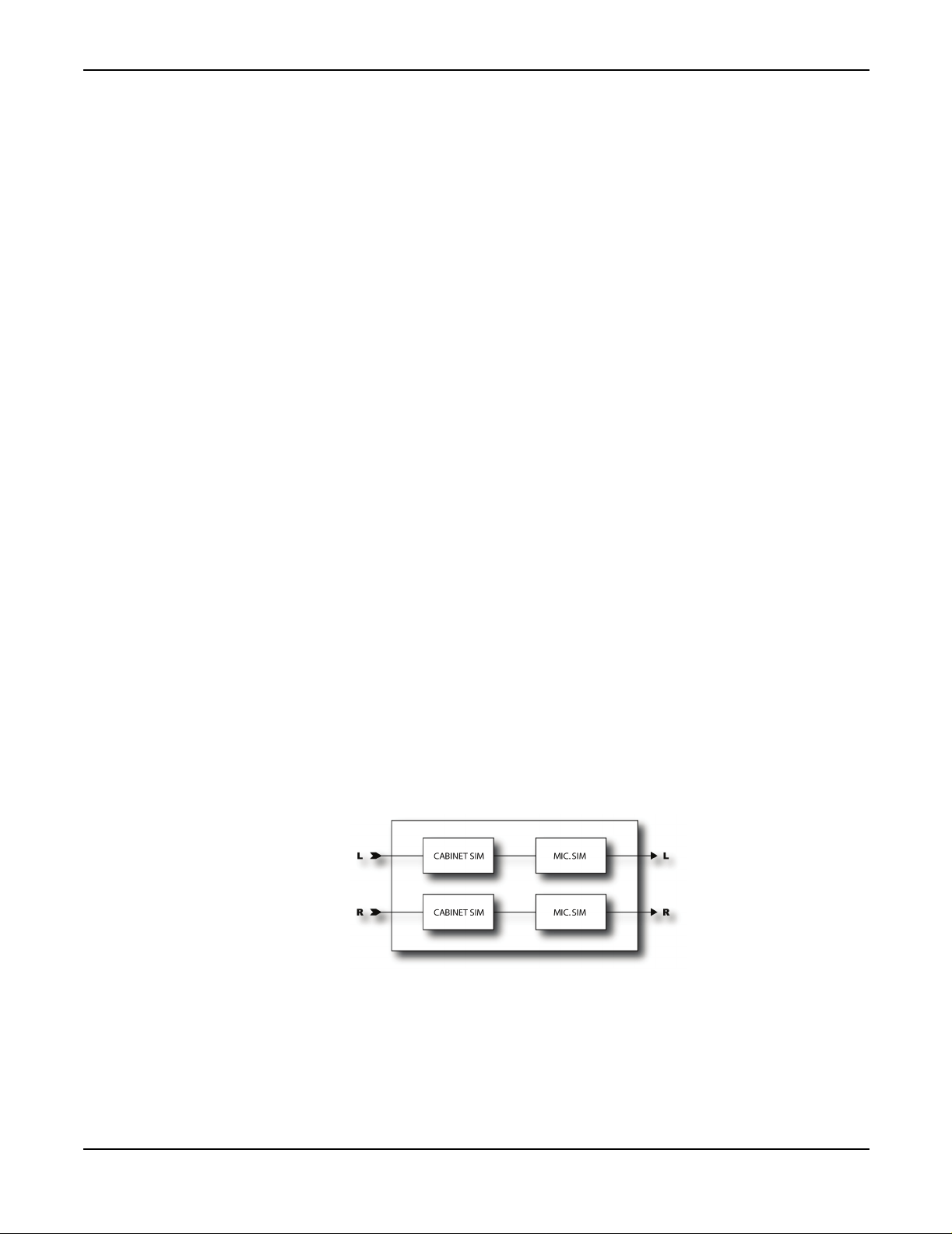
The Effects
TONESTACK FREQ -
This control allows you to alter the center frequency of the tone controls. You
can use this to change the character of the preamp. This parameter defaults to a value for each type
but can be overridden if desired. When using the passive tone stack this control also works.
However, if you change the tone stack type to anything other than th e default, the frequency reading
will not necessarily be correct although the control will still alter the frequency.
XFORMER LF -
This control allows you to alter the lower cutoff frequency of the “output
transformer”. Increase this value to simulate an old, under-designed transformer as was common in
some vintage amps. This parameter defaults to a value for each type but can be overridden if
desired.
XFORMER HF -
This control allows you to alter the upper cutoff frequency of the “output
transformer”. Decrease this value to simulate narrow bandwidth transformers as were common in
some vintage amps. This parameter defaults to a value for each type but can be overridden if
desired.
TONE LOCATION -
This control allows you to alter the location of the tone stack. “Pre” places the
tone stack at the input to the amp, “post” places the stack between the preamp and power amp. This
parameter defaults to a value for each type but can be overridden if desired.
PRESENCE FREQ -
This control allows you to alter the center frequency of the presence control.
This parameter defaults to a value for each type but can be overridden if desired.
SPKR RES FREQ -
STABILIZER -
This would happen in a real amplifier as well. The
values to ensure stability.
LEVEL, P AN, BYP MODE -
Cabinet Simulator
The Axe-Fx contains 20 cabinet simulations. These simulations recreate the tonal characteristics of
a variety of different speaker and cabinet configurations. More than just simple filters, the cabinet
simulator actually captures the subtle frequency response variations inherent in a real guitar
speaker.
This control allows you to alter the resonant frequency of the speaker cabinet.
Under certain extreme settings of
DEPTH
STABILIZER
and
DAMP
the simulation may go unstable.
switch alters the “grid capacitor”
These are the standard output mixer controls.
56
Page 60

The Effects
The simulator is true stereo allowing different speaker/mic combinations for each channel. This
allows setting up a dual amp configuration easily. Simply run AMP1 with its pan control fully left
and AMP2 with its pan control fully right. Sum their outputs into a cabinet block and set the left
cabinet and mic types for AMP1 and the right cabinet and mic types for AMP2.
Parameters
TYPE L/R -
•
up with a Plexi model and crank out some Zep.
•
for roots blues leads.
•
•
•
Selects the cabinet simulation. The following simulations are available:
1x6 Oval
1x8 Tweed
1x10 Gold
1x10 Blue
1x12 Tweed
- 6x9 oval (like in an automobile) speaker used in some early amplifiers. Match this
- Single 8" speaker. Good match for the Blues distortion. Really thin and cutting
- Single 10" Vintage speaker.
- Single 10" Alnico "Blue" speaker.
- Based on the original 12" speaker used in the early "Tweed" amplifiers.
•
1x12 Black
•
1x12 Brit
•
2x12 Black
•
2x12 Brit
•
2x12 Cust
of various "Boutique" amplifiers.
•
4x10 Bass
•
4x12 Recto
mid-scooped sound.
•
4x12 Brit
drivers.
•
4x12 20w
power drivers and unique response.
•
4x12 25w
•
4x12 75w
match for the Metal or Hellbeast Amp Simulations.
- Based on the single 12" speaker used in the "Blackfaced" tube amps.
- Based on the single 12" speaker used in the British tube amps.
- Based on the dual 12" speaker cabinet used in the "Blackfaced" tube amps.
- Based on the dual 12" speaker cabinet used in the British tube amps.
- A "custom" dual 12" speaker cabinet emulation based loose l y on the evaluation
- Based on the venerable "Tweed Bassman" amplifier.
- Matches up nicely with the Amp Simulation of the same name for that chunky,
- Based on the sound of modern British cabinets equipped with “vintage” mid-power
- Captures the essence of the early British 4x12 speaker cabinets with their low-
- Based on the sound of the British 4x12 cabinets prevalent in the 1970's.
- Based on the sound of the British 4x12 cabinets prevalent in the 1980's. A good
57
•
4x12 30W
•
2x12 Tweed
•
4x12 Green
•
2x12 Blue
•
4x10 Alum
- Based on the sound of a newer 4x12 cabinet with reissue 30W speakers.
- Based on the original 12" speaker used in the early "Tweed" amplifiers.
- Based on the sound of a classic 4x12” cab with green labeled speakers.
- Based on the sound of two classic American 12” speakers with blue labels.
- Based on the sound of a bass cabinet with aluminum drivers.
Page 61

The Effects
•
USER n
- Selects one of the user IR slots (see below).
Drive
MIC L/R -
Selects the microphone simulation type. There are eight different types based on classic
microphones that are popular for micing guitar cabinets.
LINK -
When ON, the right channel speaker and mic type change when the left channel type is
changed allowing for quick evaluation of the various types. You can still override the right channel
types if desired.
LEVEL L/R -
PAN L/R -
Sets the output level for the left and right speaker/mic.
Sets the output panning of the speaker/mic. Each speaker/mic combo can be panned in
the stereo field. By default they are panned 25% from full left/right. Adjust this control to obtain
the desired amount of separation.
DRIVE -
Sets the input drive level. This can be used to simulate speaker break-up.
User Cabinets
The Axe-Fx has the ability to import cabinet impulse responses (IR’s) and use them instead of the
internal models. The responses may be loaded into the Axe-Fx non-volatile memory via a MIDI
TYPE
utility. Once loaded, you can select which IR to use with the
control.
The drive block replicates the effect of classic “stomp boxes”. They range from sublime to intense.
Use caution when putting a drive before a high-gain amp as excessive noise and squealing may
occur. Drives work best before low and medium gain amps.
Parameters
TYPE -
give a raspy sound. The overdrive (OD) types are based on a cold-cathode tube model and give a
warm, mellow overdrive tone. The boost types don’t distort much unless the drive is set quite high
and are primarily tone-shaping and overdrive devices. The distortion types (dist) are based on a
variety of tube and solid-state models and give classic distortion tones. The following types are
available:
Selects the type of drive effect. The fuzz types are based on a hard-clipping distortion and
•
Rat Fuzz
•
PI Fuzz
•
Tube OD
•
Super OD
•
Treb Boos
- Based on a high-gain, raspy fuzz good for searing lead work.
- A more mellow but fuzzy distortion sound
- A fairly neutral distortion sound with just a bit of low-frequency roll-off.
- Midrangey, honking tone with a good snarl.
t - A bright, trebly sound good for overdriving medium gain amps. Particularly
effective on darker amps like Class A. This type has a LOT of treble boost and can easily cause
pickup squeal when used with a high-gain amp type.
58
•
Mid Boost
- A custom mid-boost overdrive.
Page 62

The Effects
•
Tube Dist
- A screaming distortion sound good for overdriving low gain amps. Based on the
legendary Japanese pedal used by many famous artists.
•
Fat Dist
•
Cust Dist
- A thick, medium gain distortion sound with a low-midrange emphasis.
- Based on a “modified”
Tube Dist
type. This type captures the most popular mods
done to the famed Japanese distortion pedal. Sounds great as a clean boost in front of a low gain
amp with the drive turned down and the level turned up.
•
Octave Dist
- The Octave Distortion uses a full-wave rectifier to recreate the classic octave
effect. Best results are usually obtained when playing around the 12th fret.
•
Super Dist
- Another Japanese distortion, this model is similar to the
Tube Dist
model but with
more highs and a slightly different tone control circuit.
•
Hard Fuzz
- As the name suggests, Hard Fuzz is a hard-clipping fuzz with little, if any,
frequency shaping. Good for nasty, vintage-style stuff.
• FET Boost - A gentle, smooth clipping booster. No frequency shap ing. Good for overdriv ing
“classic” amp types.
• Tape Dist- Simulates the clipping of an over-driven reel-to-reel tape deck.
DRIVE -
TONE -
LEVEL -
BYP MODE -
Pitch Shifter
The Axe-Fx Pitch Shifter has six basic modes of operation: Detune, Fixed Harmony, Intelligent
Harmony, Whammy, Octave Divider, and Crystals. The mode is selected on the
The Pitch Shifter can use one of two different algorithms when in the Fixed Harmony or Whammy
modes. The algorithm is selected using the
will track the pitch of the incoming note and adjust various internal parameters accordingly. Setting
PITCH TRACK to OFF ignores the pitch data and uses fixed parameter values. With pitch tracking
off the sound can waver or flutter depending upon the note(s) played. With pitch tracking on the
sound is typically smoother but complex chords may cause pitch instabilities.
The Pitch Shifter also allows you to select the source of the pitch data that the shifter will use when
making pitch calculations. The global detector is unaffected by routings and is usually the best
choice for single note usage. The integrated detector uses the signal input to the pitch block
including any feedback within the block. This can enhance pitch stability when using feedback,
whether internally, using the
global detector and pitch feedback the pitched notes may sound a bit off if you stop playing since
there will be no signal to determine pitch from. By using the internal detector the pitch block is
always obtaining pitch information even when you stop playing.
Sets the input drive level.
Controls the tone of the effect.
Sets the output level of the block
Selects the bypass mode of the block.
FEEDBACK parameters, or using the feedback blocks. When using the
TYPE
page.
PITCH TRACK control. When set to ON, the Pitch Shifter
59
Page 63

The Effects
The integrated detector may not work as well, however, if the data input to the block is distorted in
amplitude or time (i.e. reverb, chorus, etc.).
The
PITCH SOURCE
parameter has two settings:
GLOBAL
- In this mode the pitch information comes from the global pitch detector connected
directly to the main inputs. This detector is optimized for speed and accuracy when playing single
notes.
LOCAL
- In this mode the pitch information comes from the integrated pitch detector connected to
the input of the pitch block. By using the input of the block as the data source this detector can
continue to track pitch if you are using feedback into the block and stop playing.
Common Parameters
The first menu page has several common parameters for the pitch block.
TYPE - Sets the sub-algorithm to use.
INGAIN - Sets the input level to the block. You can use this to control the amount of signal input to
the pitch shifters. Often times this is attached to a modifier to allow swell-type effects.
PITCH SOURCE - Selects the source of the pitch information. See description above.
Detune
The Detune mode creates two voices that are slightly detuned from the input. The amount of
detuning is adjustable between -50 and +50 cents. This mode is useful for creating double-tracked
sounds or chorus-like effects.
VOICEn DETUNE - Sets the detune amount for each voice. Attaching an LFO to these can be used
to create chorus effects.
VOICEn LEVEL - Sets the volume level of the voice.
VOICEn PAN - Sets the panning of the voice.
VOICEn DELAY - Sets the delay time of the voice.
Fixed Harmony
The Fixed Harmony mode creates two voices that are fixed intervals from the input.
MASTER PITCH - Multiplies the pitch shift by this amount. For example, if the shift is set to 12
semitones and the Master Pitch is 50%, the shift amount will be six semitiones.
MASTER DELAY - Multiplies the delay values by this amount.
MASTER FEEDBACK - Multiplies the feedback values by this amount.
MASTER PAN - Multiplies the pan values by this amount.
60
Page 64

The Effects
MASTER LEVEL - Multiplies the level values by this amount.
VOICE1,2 DETUNE - Sets the detune amount of the voice in cents. The range is +/- 50 cents. You
can attach a controller to the detunes by pressing enter.
VOICE1,2 SHIFT - Sets the shift amount of the voice in half-steps. The range of shift is +/- 12 half-
steps.
VOICE1,2 LEVEL - Sets the volume level of the voice.
VOICE1,2 PAN - Sets the panning of the voice.
VOICE1,2 DELAY - Sets the delay time of the voice as a function of the tempo.
VOICE1,2 DLYTEMPO - Locks the delay time to the global tempo. For example, if the global tempo
is 120 bpm and the tempo is set to a quarter note (1/4) then the delay time will be 500 ms. To ignore
the global tempo set the tempo control to
VOICE1,2 FEEDBACK - Sets the feedback of the voice to the input. By delaying and feeding a
NONE.
voice back strange pitch effects can be created as the note is translated pitch again and again.
PITCH TRACK - Setting this to ON instructs the pitch shifter to track the pitch of the input. For
single note work this provides improved results. For chordal work this should be set to
OFF as the
pitch tracker obviously cannot determine the pitch of simultaneous tones.
TRACK ADJUST - This control allows fine-tuning the pitch shifter “splice length”. For large shifts
this control can help improve the quality of the shifted note.
Intelligent Harmony
The Intelligent Harmony mode creates two voices that track the note you’re playing and remain
within the key.
MASTER DELAY - Multiplies the delay values by this amount.
MASTER PAN - Multiplies the pan values by this amount.
MASTER LEVEL - Multiplies the level values by this amount.
VOICE1,2 DETUNE - Sets the detune amount of the voice in cents. The range is +/- 50 cents. You
can attach a controller to the detunes by pressing enter.
KEY - Sets the key that the harmony will be in.
61
SCALE - Sets the type of scale (or scale mode) that the harmony will use. Examples are Ionian
(major), Aeolian (minor), Whole Tone, etc.
TRACK MODE - Sets mode in which the harmony will track the input. SMOOTH allows the
harmony note to follow bends and vibrato in the input.
STEPPED locks the harmony to the nearest
chromatic tone.
Page 65

The Effects
TRACKING - Controls the tracking of the pitch shifter. Adjust for best sound. Higher values tend
to sound better for higher shifts and vice-versa.
GLIDE TIME - Sets the rate at which the harmony moves from the existing pitch to a new pitch.
VOICE1,2 HARMONY - Sets the scale degree the voice will sound.
VOICE1,2 DELAY - Sets the delay time of the voice in milliseconds.
VOICE1,2 DLYTEMPO - Locks the delay time to the global tempo. For example, if the global tempo
is 120 bpm and the tempo is set to a quarter note (1/4) then the delay time will be 500 ms. To ignore
the global tempo set the tempo control to
CUSTOM NOTES - Sets the number of notes when using a custom scale. Custom scales can have
NONE.
between four and eight notes.
TONIC - Sets the reference note for entering the custom scale. This is not a stored parameter and
only serves to aid in defining the custom scale. Setting this to “C” allows defining your custom scale
with C as the tonic. The actual key that the harmony will be in is set using the KEY parameter.
Classic Whammy
The Whammy mode allows control of the pitch shift via a control knob (normally you would
connect this knob to a controller such as an expression pedal). There are two sub-modes: WhammyUp and Whammy-Down. The difference between the sub-modes is the direction of the pitch shift.
In Whammy-Up mode the pitch increases as the control is increased. In Whammy-Down mode the
pitch decreases as the control in increased.
MODE - Selects the Whammy mode. Various amounts of shift are possible up to two octaves up
and down.
CONTROL - Adjusts the output pitch. Attach to a controller for dynamic control of the pitch.
PITCH TRACK - Setting this to ON instructs the pitch shifter to track the pitch of the input. For
single note work this provides improved results. For chordal work this should be set to off as the
pitch tracker obviously cannot determine the pitch of simultaneous tones.
TRACK ADJ - This control allows fine-tuning the pitch shifter “splice length”. For large shifts this
control can help improve the quality of the shifted note.
Octave Divider
The Octave Divider creates two new notes one and two octaves below the input. This effect
simulates the classic effect and works by actually turning the input into a square wave and then
dividing the signal by two using flip-flops. Like the classic effect, this effect only works on single
notes and works best on notes above the fifth fret. Experiment with pickup selection and effect
placement to achieve the best results.
62
LVL1,2 - Sets the volume level of the octaves.
Page 66

The Effects
Crystals
PAN1,2 - Sets the panning of the octaves.
MIX - Sets the mix between the effect and input.
The Crystals pitch shifter is similar to the Fixed Harmony but optimized for special effects. It
features much longer possible “splice” times allowing for interesting delay effects. It also features
a reverse switch and extensive tempo options.
MASTER PITCH - Multiplies the pitch shift by this amount. For example, if the shift is set to 12
semitones and the Master Pitch is 50%, the shift amount will be six semitiones.
MASTER FEEDBACK - Multiplies the feedback values by this amount.
VOICE1,2 DETUNE - Sets the detune amount of the voice in cents. The range of +/- 50 cents. You
can attach a controller to the detunes by pressing enter.
VOICE1,2 SHIFT - Sets the shift amount of the voice in half-steps. The range of shift is +/- 12 half-
steps.
VOICE1,2 LEVEL - Sets the volume level of the voice.
VOICE1,2 PAN - Sets the panning of the voice.
VOICE1,2 DELAY - Sets the delay time of the voice in milliseconds.
VOICE1,2 DLYTEMPO - Locks the delay time to the global tempo. For example, if the global tempo
is 120 bpm and the tempo is set to a quarter note (1/4) then the delay time will be 500 ms. To ignore
the global tempo set the tempo control to
VOICE1,2 SPLICE - Sets the splice time of the voice in milliseconds.
VOICE1,2 SPLTEMPO - Locks the splice time to the global tempo. For example, if the global
NONE.
tempo is 120 bpm and the tempo is set to a quarter note (1/4) then the time will be 500 ms (one echo
per beat). To ignore the global tempo set the tempo control to
VOICE1,2 FEEDBACK - Sets the feedback of the voice to the input. By delaying and feeding a
NONE.
voice back strange pitch effects can be created as the note is translated pitch again and again.
DIRECTION - Sets the “direction” of the splice playback. Try setting to REVERSE for spacey
effects.
FEEDBACK TYPE - Selects the type of feedback. DUAL sends the individual voices back to their
BOTH
respective delay lines.
sends each voice to the opposite delay line.
PONG
mixes the voices and sends them back to both delay lines. PING-
63
HICUT FREQ - Sets the high-frequency rolloff of the pitched signal using a 12 dB / octave filter.
This can be used to adjust the timbre of the voices.
Page 67

The Effects
CROSSFADE - Sets the amount of overlap in the audio snippets. A low setting will make the echoes
more discrete whereas a high setting will tend to smear the echoes.
Stereo Enhancer
The Stereo Enhancer is used to increase the apparent stereo separation between the left and right
outputs. When used judiciously it can make a stereo track appear “fuller” and “wider”.
WIDTH -
effect is achieved. Certain frequencies may cancel each other at various settings, experiment with
this to achieve the desired enhancement and frequency response.
INVERT -
control to adjust frequency and apparent widening.
PAN -
control may be used to compensate for this.
Sets the phase difference between the left and right channels. Adjust until the desired
Allows inversion of the left or right channel if desired. Use in conjunction with the width
Sometimes the effect will cause a shift in the apparent localization of the instrument. The pan
Effects Loop / Aux. Out
The Axe-Fx has a fully routable effects loop which allows you to use outboard processors anywhere
in the signal chain. The effects loop can also be used as an auxiliary output for live stage monitoring
through an amplifier and cabinet or as a general purpose output. To use the effects loop as an
auxiliary output the output of the block is simply not connected. Alternatively you can place the
effects loop directly in the signal chain but not connect anything to the
jack. The Axe-Fx senses if the effects return is not used and then just uses the loop as an output.
To use the effects loop as an on-stage monitor with a guitar amp (or head and cabinet) place the loop
BEFORE any cabinet simulation blocks. For example, if you want to send a fully processed, stereo
feed to the P.A. system and monitor your sound on-stage you would set up a chain like the
following:
INPUT2 / EFF. RETURN
64
AMP - CHORUS - DELAY - REVERB - EFFECTS LOOP - CABINET
Note that the effects loop is before the cabinet. The main output would then be fully processed
including the cabinet simulation. If you were to send this signal to an amp/cabinet combination it
would probably be excessively muddy.
If your on-stage monitoring equipment is full-range then you can place the effects loop after the
cabinet or simply use the un-balanced
jacks to the P.A.
OUTPUT1
jacks for monitoring and connect the balanced
Page 68
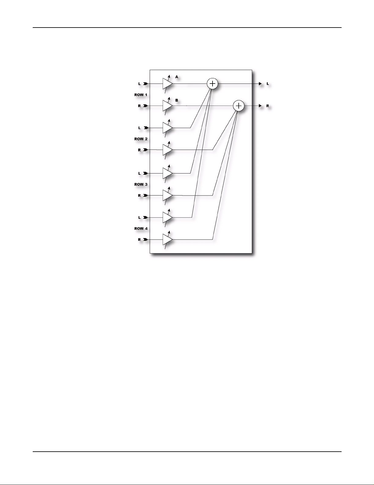
The Effects
Mixer
The Mixer is a simple linear mixer that mixes the four rows feeding the block according to the gains
for each row. The Mixer allows you to fine-tune levels, or cross-fade between effects. This is
especially useful for cross-fading amps or delays.
Each gain control corresponds to a row in the routing matrix. To adjust, for example, the gain for
the effect in row two preceding this block, simply adjust
The
PAN
controls allow you to select the balance of left and right from each row summed into the
GAIN2
.
outputs. This is useful if you have differing signals in the left and right channels on a row. For
example, you can use set up a routing where two amp blocks feed a single cabinet block with one
amp panned hard left, the other panned hard right. You can now fade between the two amp blocks
using the
PAN
control. Attach the
PAN
control to a modifier for real-time control.
The controls are linear (as opposed to logarithmic like most other gain controls). This makes setting
up cross-fades much easier.
65
Page 69

The Effects
Volume / Pan
The Volume / Pan block is a simple level and pan control block. It allows you to insert level and
pan controls at any point in the routing matrix. It is a great way to control the level into or out of
effects using an expression pedal.
VOLUME -
BALANCE -
VOLUME TAPER -
Sets the volume level out of the block.
Sets the balance (L/R) out of the block.
Sets the “taper” of the volume control. Linear selects a linear taper. LOG A
selects a logarithmic taper where the attenuation is 10 dB when the volume control is at 5.00.
B
selects a log taper where the attenuation is 20 dB at midscale.
Feedback Send / Return
The Feedback Send and Return blocks allow you to feedback sound from one poin t in the routing
to any other point.
The Send block has no parameters, while the Return block has a basic mixer. Adjust the
to set the ratio of direct and feedback signals.
Best results are achieved when feeding back a pure delayed signal. If any direct signal is fed back
the resulting loop will usually be unstable and/or sound strange due to phase cancellation.
Warning: Use caution with the Feedback blocks as you can easily program an unstable loop and cause
internal clipping of the signal and/or very high sound levels which can damage your hearing. Always
start with the
instability return the
MIX
control on zero and slowly bring it up. If you start to hear squealing or other signs of
MIX
MIX
control
control to zero and analyze your routing for possible causes of instability.
LOG
66
Page 70

Controllers and Modifiers
Controllers and Modifiers
The Axe-Fx allows control over many of the various effect parameters. In essence a controller is
like a robot that turns a knob for you. There are two basic types of controllers: internal and external.
Internal controllers are automatic controllers that are generated by the Axe-Fx based on various
parameters and conditions. External controllers are those generated by a MIDI device or a pedal for
example. A modifier is a transform from the value generated by the controller to a value given to
the parameter. Modifiers allow you to change the direction a parameter moves, smooth the response
and select which controller is attached to the parameter. A modifier tells the robot how to move the
knob.
Controllers
The Axe-Fx controllers are internal and external sources that generate control information. This
information can then be used to vary a parameter in real-time. Internal controllers automatically
generate control information, external controllers generate control information based on input from
the user, typically from the movement of an expression pedal. The control information is given to
a modifier which in turn varies the desired parameter.
Tempo
The most fundamental internal controller is the tempo controller. The tempo controller is special in
that it cannot be directly connected to a parameter but many "rate" or "time" parameters can be set
to depend on it. To use the tempo controller simply set the
desired note duration. To set the Tempo either turn the knob or tap the desired tempo in using the
TEMPO
There are two tempo constructs in the Axe-Fx. The System Tempo is the tempo currently being
used. The Global Tempo is the last entered tempo. Entering a new tempo automatically updates the
System Tempo and sets the Global Tempo to equal the System Tempo. The current System Tempo
is saved with a preset during a preset save operation.
Presets can either set the System Tempo to the tempo value stored in the preset, which is the tempo
at the time the preset was saved, or the Global Tempo. This is done using the
parameter described below.
TEMPO -
by tapping or by MIDI clock, the System and Global Tempos are set to this value. The Global
Tempo is not affected by the tempo stored with a preset when the preset is recalled and remains in
effect.
TEMPO TO USE -
Axe-Fx to set the System Tempo to the tempo stored with the preset. Selecting
unit to use the last entered tempo. If the value is
stored with the preset, but the Global Tempo will remain at the last entered tempo. Recalling a
preset with this value set to
button. Tempo can also be tapped in using a pedal or MIDI CC message.
Sets the current System Tempo. Whenever a tempo is entered, whether via this control or
Selects what tempo to use when recalling the preset. Selecting
PRESET
GLOBAL
will load the Global Tempo into the System Tempo.
TEMPO
the current tempo will change to the tempo
parameter of the effect to the
TEMPO TO USE
PRESET
GLOBAL
tells the
tells the
67
Page 71

Controllers and Modifiers
LFO's
AUTO DEL AY -
When set to ON, any delay blocks that are bypassed will become active whenever a
new tempo is input. This allows recalling a preset with a delay block bypassed and then
automatically activating the delay when tapping in a new tempo.
The Axe-Fx contains two Low Frequency Oscillators (LFO's) that can generate various lowfrequency waveforms for use in parameter modulation. The controls for each are identical.
TYPE -
RATE -
DEPTH -
DUTY CYCLE -
OUTB PHASE -
Sets the waveform type.
Sets the frequency of the LFO.
Sets the amplitude of the LFO.
For all waveforms except sine this allows you to vary the shape of the wave.
Sets the phase of the secondary output (Output B). At maximum the secondary
output is out of phase with the primary output (Output A).
TEMPO -
Locks the LFO frequency to the current tempo. This overrides the RATE control.
ADSR's
The Axe-Fx contains two Attack-Decay-Sustain-Release (ADSR) generators. These can be use to
generate sequences that can then be used to control parameters. The graph shows the relative shape
of the ADSR curve as its parameters are adjusted.
MODE -
Selects the trigger mode of the ADSR:
•
ONCE:
•
LOOP:
•
SUSTAIN:
The sequence plays when the threshold is exceeded.
The sequence repeats as long as the signal is above the threshold.
The sequence stays at the sustain level until the signal drops below the threshold.
The remainder of the sequence is then played.
RETRIG -
When Retrig is on, sequences will reset to the beginning whenever the threshold is
crossed from below to above.
ATTACK -
DECAY -
SUSTAIN -
LEVEL -
The attack or rise-time of the sequence. This is the first line in the graph.
The time to go from the peak level to the sustain level. The second line in the graph.
The time the sequence remains at the sustain level. The third, flat, line.
The sustain level in percent of full-scale.
68
RELEASE -
The time to go from the sustain level to zero. The last line in the graph.
Page 72

Controllers and Modifiers
THRSHLD -
Sequencer
The Sequencer generates a sequence of values. When the last stage of the sequence is reached the
sequence starts over. The Sequencer can be used to generate repetitive patterns in time with the beat
of the song.
RATE -
sequencer to step through the stages at a rate of one stage per second.
TEMPO -
time signature to lock the rate to the current tempo.
RUN - Starts and stops the sequencer. You can attach a modifier to this to control the sequencer via
any of the available controllers.
STAGES -
will step through the stages as 1, 2, 3, 1, 2, 3, 1, etc.
STAGEn -
The threshold level in dB. When the signal crosses this value the sequence is triggered.
Sets the rate at which the sequence is stepped through. A rate of 1 Hz will cause the
Locks the rate to the global tempo. Set to none for manual control of rate, set to the desired
Sets the number of stages in the sequence. For example, if
STAGES
is 3, the sequencer
Sets the value at that stage of the sequence.
NOTE: The Sequencer features a random sequence generator. When in the Sequencer menu pressing
ENTER
Envelope
The Envelope follower follows the envelope of the input signal. The harder you play the greater the
value out of the Envelope follower. The Envelope follower makes possible dynamic parameter
control such as ducking delay or touch-wah.
THRESH -
the follower will track the envelope of the input with a rate set by the attack time. If less than this
value the output will decay at the release rate.
ATTACK -
RELEASE -
GAIN -
the follower.
will load a random set of values into the stages.
The threshold level in dB. When the input signal is greater than this value the output of
The rate at which the follower output follows signals increasing in power.
The rate at which the follower output follows signals decreasing in power.
When using long attack times this can be used to compensate for the lower output level from
69
Page 73

Controllers and Modifiers
Pitch
The Axe-Fx has a fast built-in Pitch detector. It is completely automatic and has no adjustable
parameters. The value from the pitch detector is proportional to the frequency of the note played,
higher notes give a higher value. If multiple notes are played at once the pitch detector will attempt
to find the lowest pitch but may not be able to lock onto it. The pitch detector works best with single
notes.
External Controllers
The Axe-Fx supports up to eight external controllers. You can attach these to the
or to any MIDI Continuous Controller (see I/O setup).
Modifiers
Modifiers act as a “middleman” between the control information from a controller and a parameter.
The data from a controller is manipulated by a modifier and then used to vary an effect parameter.
The Axe-Fx contains 16 modifiers. In its simplest form a modifier simply passes the data unaltered
from a controller to a parameter. For example, an LFO can be used to directly control the panning
of an effect output. Often times, though, you will want to manipulate the data from a controller. A
modifier allows you to change the response of a parameter to a given controller.
The first step in using a modifier is attaching it to the desired effect parameter that you wish to
control. To attach a parameter to a controller the parameter must controllable. Controllable
parameters are indicated by a symbol beneath the knob:
Indicates Parameter
is Controllable
PEDAL1,2
jacks
70
When the parameter is attached to a controller via a modifier the indicator has a line through it
indicating that it is attached. For parameters in a list, the symbol above appears to the right of the
parameter in the list.
To attach a controller to a parameter, select the parameter with the navigation buttons then press
ENTER
Once the menu is brought up the modifier must be attached to a source controller. This is the control
information source that will be used to vary the parameter. You can choose any of the internal or
external controllers as a source (or none to remove the modifier). Once the modi fier is attached to
a source you can vary the response curve and the damping to suit the desired response.
. This brings up the
MODIFIER
menu.
Page 74

Controllers and Modifiers
To remove a modifier select the parameter with the navigation but ton s an d press
ENTER
. Set the
source to none then press exit. This will remove the modifier and restore the parameter’s value to
its stored value.
Parameters
SOURCE -
different sources available:
•
•
•
•
•
•
•
•
assigned to the pedal inputs or to MIDI continuous controllers (see I/O Setup).
This is the controller that will be used to control the parameter. There are a variety of
NONE
- Controller is detached.
LFO1A/B
LFO2A/B
ADSR1/2
SEQNCR
ENVLPE
PITCH
EXTRNx
- Selects the 'A' or 'B' output of LFO1 (see above).
- Selects the 'A' or 'B' output of LFO2 (see above).
- Selects ADSR1/2.
- Selects the Sequencer.
- Selects the Envelope follower.
- Selects the Pitch detector.
- Selects an External Controller. There are eight external controllers. These can be
START -
MID -
END -
SLOPE -
SCALE -
OFFSET -
The
Sets the start point for the transform.
Sets the mid point for the transform.
Sets the end point for the transform.
Sets the shape of the curve.
Sets the scale factor for the transform. The resulting curve is multiplied by this value.
Sets the offset. The curve is offset by this value
SCALE
and
OFFSET
parameters allow the user to position the modifier and control the excursion
once an initial transfer function is set with the other parameters. For simple linear transfer functions,
one need only use the
DAMPING -
Sets how fast the output changes with the input. To slow the response rate increase the
SCALE
and
OFFSET
parameters, leaving the others at their default values.
damping. This can be used to "de-click" a controller that changes rapidly.
This is especially useful when using controllers that have step-change responses such as an LFO
with a square-wave or sawtooth waveform or the sequencer. In these examples the value of the
controller jumps from one value to another instantly. If these values are then connected to a
parameter, that parameter will jump from one value to another instantly as well. Many times this
can cause an audible click or pop, especially if the parameter is a volume level or frequency
parameter. By increasing the damping, the parameter will not jump to the new value but slide to the
new value at a rate dictated by the damping value.
71
Page 75

Controllers and Modifiers
The damping control is also effective when using an expression pedal to control a parameter. It can
help smooth out the pedals response, especially if the pedal’s potentiometer has gotten “scratchy”.
AUTO ENG -
the connected controller. This can be used, for example, to engage a Wah just by moving an
expression pedal.
When set to ON, automatically engages the target effect block when activity occurs on
Detaching a Controller
To detach a controller set the source to
NONE
and press
EXIT
.
72
Page 76

Global Parameters
Global Parameters
The Axe-Fx Global Parameters menu is accessed by pressing the
GLOBAL
menu button. The
Global Parameters allows you to set the overall tone and mix of the Axe-Fx. These settings are
stored independently of the presets and restored at each power-on.
There are four pages:
OUT1
and
The
OUT2
CONFIG, OUT1, OUT2
and
MIX
.
pages allow fine tuning of the tone for each of the outputs. Here you can make
adjustments to the basic tone of your Axe-Fx that affects all presets. This comes in handy wh en
using the Axe-Fx in different environments where the acoustics may vary.
BASS, MID, TREBLE -
PHASE -
This control allows you to invert the polarity of the output to compensate for a signal
These tone controls affect the output selected for all presets.
inversion elsewhere in you setup.
The
MIX
page allows overall control of the reverb and effects mix. As previously discussed the
Global Mix allows you to vary the reverb and effects mix across all presets. This is useful when
using the Axe-Fx in different environments where the ambience may vary. Note that the effects mix
only affects those effects that have their
The
CONFIG
page allows for global configuration of the amp and cabinet simulations as well as
GLBL MIX
control set to ON.
delay spillover control.
POWER AMP -
Setting this to
BYPASSED
defeats the power amp simulation for all presets. This is
useful when you are using the Axe-Fx with a tube amp.
CABINET -
Turning the
CABINET
to
BYPASSED
bypasses the Cabinet blocks in all presets. Use this
when you are using the Axe-Fx into an amplifier > guitar cabinet setup. This allows using presets
with cabinets in them in varying situations. For direct recording or into a full-range sound
reinforcement system (i.e. PA or home stereo) turn
CABINET
to
ACTIVE
(enable the Cabinet
Emulators). If connecting to a guitar amp with integral speakers or a separate amplifier and guitar
cabinet turn
CABINET
to
BYPASSED
. This defeats the Cabinet Emulators and presents the full-range
signal to the amplifier/cabinet resulting in the proper tonal response. If this is not done the high
frequencies will be excessively attenuated possibly resulting in a muffled or muddy sound.
DEFAULT TONESTK -
whenever the amplifier type is changed. If set to
active equalization for the tone controls. If set to
This parameter allows you to select the type of tone stack that will be selected
ACTIVE
, the Axe-Fx will select the semi-parametric
PASSIVE
, the Axe-Fx will select the passive tone
stack style tone controls. In this mode the tone stack selected is the default tone stack appropriate
for the specific amp type. You can changed the tone stack to a different model or even back to active
using the advanced amp menu.
DELAY SPILL -
Setting this to
ON
disables the clearing of all delay lines during preset change. This
in turn allows delays, reverbs and any other delay based effects to “spillover” to the new preset
OFF
Setting this to
clears all delay lines and prevents any spillover.
73
Page 77

Tuner
Tuner
Pressing the
page is the basic tuner display. The second page allows you to configure the tuner and the third page
allows you to enter custom tuning offsets.
CAL -
MUTE -
USE OFFSETS -
applied to the tuner display.
TUNER
This sets the reference frequency for the tuner.
When set to ON this mutes the sound out of the Axe-Fx when in the tuner menu.
button brings up the Axe-Fx tuner display. There are three pages. The first
When set to ON the custom temperament offs ets entered on the
OFFSETS
page are
74
Page 78

Utilities
Utilities
LCD
Preset
The Utilities menu consists of the
On this page you can adjust the contrast of the LCD.
LCD, PRESET, STATUS, RESET
and
FIRMWARE
pages.
Preset Dump
These functions allow you to save presets to a MIDI librarian (or MIDI librarian software on a PC).
Connect
select the function and press
To restore a preset from a MIDI librarian connect the device to
into the Axe-Fx. The Axe-Fx automatically loads the data into its edit buffer. You can then save the
downloaded data to the location of your choice.
To dump a bank of presets simply select the desired bank to dump and press
contains presets 0 through 127, Bank B contains 128 through 255 and Bank C contains presets 256
- 383. It may take several minutes to dump all the data in a bank. When saving the data to your
librarian device (or PC) be sure to name the saved data to indicate the bank in which the data
originated (i.e. BankA.syx). This will eliminate confusion if the need arises to restore a bank.
MIDI OUT
to the MIDI librarian device. To save a preset simply recall the desired preset,
ENTER
. The preset data is dumped in SysEx format.
MIDI IN
and send the SysEx data
ENTER
. Bank A
It is good practice to back up your presets regularly just as it’s good practice to back up the data on
your computer.
To restore a bank of presets connect the MIDI librarian to
Axe-Fx. The Axe-Fx automatically recognizes the data as a Bank Dump and loads the data into its
battery backed memory. CAUTION: THIS WILL OVERWRITE ALL DATA IN THE BANK.
Data from one Axe-Fx can be loaded into another Axe-Fx using this same method. Simply connect
the
MIDI OUT
then be loaded into the second unit.
of the first Axe-Fx to the
MIDI IN
MIDI IN
of the second. A bank from the first unit can
and send the SysEx data to the
Preset Update
This function allows you to update all presets to the latest protocol. The Axe-Fx can read presets
stored in either version 1.0 or 2.0 protocol. When a preset is saved it is saved in the latest protocol.
If you’ve just updated the firmware to 2.0 or later you can convert all your presets to the latest
protocol by using this function.
75
Page 79

Utilities
Preset Backup
This function allows you to save the first 64 presets to the Axe-Fx’s non-volatile FLASH memory.
In the event that the internal battery fails or someone messes with your presets you can recall (see
below) these presets back into main memory. By arranging your presets so that the ones you use for
performance are in the first 64 locations you can save these to FLASH memory and be able to recall
them in an emergency.
Backup Recall
This function allows you to recall the first 64 presets from the Axe-Fx’s non-volatile FLASH
memory. The Axe-Fx automatically checks to see if the FLASH memory contains valid preset data
and aborts the procedure if none is found.
NOTE: When updating firmware the entire FLASH memory is erased and any presets backed up will be
erased as well. After updating, perform the Preset Backup function to re-save the presets. It is good
practice to back up your presets regularly both to the FLASH and also to an outboard storage d evice
such as a PC so that if your unit is lost or stolen you can reload your custom p resets into a new unit and
avoid lengthy reprogramming.
Status
Reset
The
STA T US
programming a VERY complicated preset you may run out of CPU power. The Axe-Fx has enough
horsepower to run at least 10 effects simultaneously. If the CPU utilization is approaching 90% you
may not be able to add a desired effect to the preset. Naturally some effects use much more power
than others, the amplifiers using the most. The Axe-Fx does not allow the total CPU load to exceed
98% as the unit could then become unresponsive.
The Axe-Fx uses worst-case scenarios in determining whether enough power is left to place an
effect and may not let you place an effect even if seemingly enough power is left. For example the
chorus can use up to 8% of the CPU if set to 8 voices and with controllers attached to all its
parameters. However it normally only uses a few percent. The Axe-Fx assumes the worst case and
checks to see if CPU utilization is less than 98 - 8 = 90%. This is done to prevent overloading the
CPU if the number of voices is increased.
Also, an effect is always running, even if bypassed so the CPU utilization does not change if an
effect is bypassed. If you need more CPU resources check to see if you have any effects bypassed
that you don’t need and, if so, remove them. This will reduce the CPU usage accordingly.
To reset all the factory parameter in your Axe-Fx select this page and press
the Global parameters, the MIDI configuration, Continuous Controller setup and Pedal
configuration. This will not clear or otherwise alter any preset information.
page allows you to monitor the input levels and CPU usage of the Axe-Fx. If
ENTER
. This will reset
76
Page 80

Utilities
Firmware
This page allows you to update the firmware of your Axe-Fx. Follow the instructions that
accompany the firmware.
77
Page 81

Tips and Tricks
Tips and Tricks
Achieving ultimate tone
Ultimate tone is the Holy Grail for guitar players and is a combination of many factors. To help you
achieve the sound you are looking for follow these guidelines:
Choose the amplifier type carefully
The amp types all have their own unique voicing and certain types are better suited to particular
tones than others. Also experiment with the power amp parameters. The Depth, Sag and Master
controls can make subtle changes to the tone of an amp that really bring out its character.
Experiment with the Drive
A lower gain amp type can turn into a raging shred machine with a Drive block feeding it. Try
putting a TS DISTORTION type in front of the Plexi amplifier type for example.
Experiment with the Cabinets and Microphones
A different Cabinet type can change the sound of an amp dramatically. Start with L/R cabinets
linked and audition the various cabs and mics. Then unlink the cabs/mics and experiment with
different cab/mic combinations. You can fill out the sound by using different types left/right and
adjusting the panning.
Use the EQ
EQ can make a HUGE difference in sound. Try placing EQ before AND after the amplifier block.
Subtle EQ adjustments can tighten up the sound or increase the depth. The Axe-Fx has a lot of EQ
resources for just this reason. Take advantage of them.
Using Your Axe-Fx with a Guitar Amp
Your Axe-Fx is equally suited for use with a full-range monitoring system or with a standard guitar
amplifier. A few prefacing comments are in order:
From the factory the Axe-Fx is designed to interface to full-range recording or sound reproduction
devices, i.e. studio monitors, sound cards, etc. The Axe-Fx fully simulates the entire audio chain of
a typical guitar rig including the preamp, power amp, effects, speaker cabinet and microphone.
Often times, however, you may wish to connect your Axe-Fx to something other than a full-range
device, i.e. a guitar amp. In this situation be aware that the guitar amp is already providing at least
the speaker cabinet part of the signal chain. If you were to leave the Cabinet Simulation active in
your Axe-Fx then the audio would basically be passing through a speaker cab in effect twice (once
in the Axe-Fx, once in the external cab). This can have a detrimental effect on the sound quality and
usually ends up being muddy as the high-frequencies are excessively attenuated and other
frequencies may be unnaturally emphasized.
78
Page 82

Tips and Tricks
If you are connecting the Axe-Fx to a tube power amp as well, then once again the signal is
effectively passed through a power amp twice (once in the Axe-Fx, once in the external tube amp).
For this reason the Axe-Fx allows you to defeat the power amp simulations and the cabinet
simulations. The power amp simulation can be defeated by turning the
block to zero. The cabinet simulation can be defeated either globally via the Cabinet Bypass switch
(in the
To use the Axe-Fx with a standard guitar amp the preferred method of connection wo uld be to plug
your guitar into the Axe-Fx and the output of the Axe-Fx into the loop return or power-amp in put
(if so equipped) of your amp. This bypasses the preamp of your guitar amp and uses only the amp’s
power amp and speaker. The Axe-Fx then provides the preamp emulation and tone shaping.
If your amp does not have an effects loop then plug the output of the Axe-Fx into the instrument
input of the amp and turn the amp’s mid control to full and the bass and treble to zero. On most amps
this will actually be a flat response. You can fine tune the tone after, if desired.
If your guitar amp is solid-state then you will probably want to use the full amp simulation abilities
of the Axe-Fx including the power amp simulation. If you are using a tube amp then you already
have a tube power amp and you may want to defeat the power amp simulation. To do this turn the
SAG
GLOBAL MIX
control in the Amp block to zero.
menu) or by bypassing or removing the cabinet block from the signal chain.
SAG
control in the Amp
Since you are running into a guitar speaker (or speakers) turn the Cabinet Simulation off in your
Axe-Fx either by disabling it globally via the
in a preset.
The Axe-Fx also works great driving a dedicated power amp and separate speaker cabinet As above
you should defeat the Cabinet Simulation (since you are already going to into a cabinet) and if using
a tube power amp you may want to defeat the power amp simulation (using the
Using Your Axe-Fx Live
The Axe-Fx is designed with live performance in mind. For the ultimate in portability you could
simply plug your guitar into the Axe-Fx and then plug your Axe-Fx into the P.A. mixing board.
Send some signal to the mains and your monitor and you’ve got great sound with minimum hassle.
A more complicated approach would be to send the fully processed sound to the mixing board but
tap off before the cabinet simulation and send that to a guitar amp or separate power amp and guitar
cabinet. To do this you can use the auxiliary outputs of your Axe-Fx. Simply place the Effects Loop
block as the second to last block in your signal chain and the Cabinet Simulator as the last block.
The signal appearing at the
whereas the signal at the
OUTPUT 2
OUTPUT 1
jacks will be perfect for sending to the P.A. system.
GLOBAL
jacks will be perfectly suitable for driving a guitar amp
menu or by bypassing or removing that block
SAG
control).
Interference
Electric guitars are extremely effective at amplifying more than just the sound of the guitar but also
the electromagnetic fields generated by TV sets, computer monitors, neon lights and illegal taxi
radios. The best defense against these sources of interference is to have a well shielded guitar and
79
Page 83

Tips and Tricks
to maximize the distance between the guitar and these sources. If you are working at a computer
consider using an LCD monitor as these do not generate the high-intensity magnetic fields that CRT
monitors do.
Maintenance
Your Axe-Fx was built using the highest quality components available. No routine maintenance is
required. To clean the unit use a mild detergent and water solution. Do not use any abrasives or
harsh chemicals as these can damage the finish of the unit.
If your unit is malfunctioning do not attempt to service it yourself. The Axe-Fx is more like a
computer than a tube amp and has no user serviceable components. TO PREVENT RISK OF
ELECTRICAL SHOCK DO NOT OPEN THE CHASSIS. If you determine that your unit is
malfunctioning please contact the factory to arrange for servicing.
Note: The Axe-Fx contains a small internal cooling fan. This keeps the CPU within proper operating
temperature under extreme ambient temperatures. You may notice a slight whirring noise if you put your
ear close to the unit. This is normal.
80
Page 84

Warranty Information
Fractal Audio Systems warrants that your new Fractal Audio Systems product, shall be free of
defects in materials and workmanship for a period of one (1) year from the original date of purchase.
During the warranty period, Fractal Audio Systems shall, at its sole option, either repair or replace
any product that proves to be defective upon inspection by Fractal Audio Systems.
Fractal Audio Systems reserves the right to update any unit returned for repair and to change or
improve the design of the product at any time without notice. Fractal Audio Systems reserves the
right to use reconditioned parts and assemblies as warranty replacements for authorized repairs.
This warranty is extended to the original retail purchaser.
This is your sole warranty. Fractal Audio Systems does not authorize any third party, incl uding any
dealer or sales representative, to assume any liability on behalf of Fractal Audio Systems or to make
any warranty for Fractal Audio Systems. Fractal Audio Systems may, at it’s option, require proof
of original purchase date in the form of a dated copy of original authorized dealer’s invoice or sales
receipt. Service and repairs of Fractal Audio Systems products are to be performed only at the
Fractal Audio Systems factory or a Fractal Audio Systems authorized service center. Fractal Audio
Systems may require advanced authorization of repairs to authorized service centers. Unauthorized
service, repair or modification will void this warranty.
Warranty Information
DISCLAIMER AND LIMITATION OF WARRANTY
THE FOREGOING WARRANTY IS THE ONLY WARRANTY GIVEN BY FRACTAL AUDIO
SYSTEMS AND IS IN LIEU OF ALL OTHER WARRANTIES.ALL IMPLIED WARRANTIES,
INCLUDING WARRANTIES OF MERCHANTABILITY AND FITNESS FOR ANY
PARTICULAR PURPOSE, EXCEEDING THE SPECIFIC PROVISIONS OF THIS
WARRANTY ARE HEREBY DISCLAIMED AND EXCLUDED FROM THIS WARRANTY.
UPON EXPIRATION OF THE APPLICABLE EXPRESS WARRANTY PERIOD (1 YEAR),
FRACTAL AUDIO SYSTEMS SHALL HAVE NO FURTHER WARRANTY OBLIGATION OF
ANY KIND, EXPRESS OR IMPLIED. FRACTAL AUDIO SYSTEMS SHALL IN NO EVENT
BE LIABLE FOR ANY SPECIAL, INCIDENTAL OR CONSEQUENTIAL DAMAGES
SUFFERED BY THE PURCHASER OR ANY THIRD PARTY, INCLUDING WITHOUT
LIMITATION, DAMAGES FOR LOSS OF PROFITS OR BUSINESS, OR DAMAGES
RESULTING FROM USE OR PERFORMANCE OF THE PRODUCT, WHETHER IN
CONTRACT OR IN TORT. FRACTAL AUDIO SYSTEMS SHALL NOT BE LIABLE FOR
ANY EXPENSES, CLAIMS, OR SUITS ARISING OUT OF OR RELATING TO ANY OF THE
FOREGOING. Some states do not allow the exclusion or limitation of implied warranties so some
of the above limitations and exclusions may not apply to you. This warranty gives you specific legal
rights, and you may also have other rights, which vary, from state to state. This warranty only
applies to products sold and used in the USA and Canada. Fractal Audio Systems shall not be liable
for damages or loss resulting from the negligent or intentional acts of the shipper or its contracted
affiliates. You should contact the shipper for proper claims procedures in the event of damage or
loss resulting from shipment.
81
Page 85

Specifications
Specifications
Front Panel Input
Connector:1/4” phone jack, unbalanced.
Impedance:1 Mohm
Max. Input Level:+12 dBu (conditioned for guitar use)
Rear Inputs
Connector:1/4” phone jack, unbalanced.
Impedance:1 Mohm
Max. Input Level:+18 dBu
A/D Conversion
Bit Depth:24 bits
Sample Rate:48 kHz
Dynamic Range:> 105 dB
Frequency Response:20 - 20kHz, +0 / -3 dB
Crosstalk:<-60 dB over full bandwidth
Analog Outputs
Connectors:1/4” phone jack unbalanced, XLR balanced (for main output)
Impedance:100 ohm
Max Output Level:+18 dBu
Dynamic Range:> 105 dB
Frequency Response:20 - 20kHz, +0 / -3 dB
Crosstalk:<-60 dB over full bandwidth
Digital I/O
Connectors:RCA Coaxial Type for S/PDIF I/O, XLR for AES Out
Format:S/PDIF - 24 bit
Sample Rate48 kHz
MIDI Interface
Input Connector:7-pin DIN (pins 6&7 connected to phantom power in jack)
Out/Thru Connectors:5-pin DIN
Pedal Interface
Connectors:1/4” TRS phone jacks
82
Format:Compatible with expression and momentary or latching pedals
General
Page 86

Specifications
Finish:Powdercoated steel chassis with anodized aluminum faceplate
LCD:128x64 dot matrix graphic display
Dimensions:19” x 3.5” x 12” (483 x 88 x 305 mm)
Weight:10 lbs 4.5 kg)
Input Voltage:100 to 240 VAC, 47 - 63 Hz (universal input)
Power Consumption:< 10 W
Backup Battery Life:> 10 years
Environmental
Operating Temperature:32 to 122 °F (0 to 50 °C)
Storage Temerature:-22 to 167 °F (-30 to 70 °C)
Humidity:Max. 90% non-condensing
(Specifications subject to change without notice)
83
 Loading...