

Page 1

Trademarks
FOXWELL is trademark of Shenzhen Foxwell Technology Co., Ltd.
All other marks are trademarks or registered trademarks of their respective
holders.
Copyright Information
©2019 Shenzhen Foxwell Technology Co., Ltd.
All rights reserved.
Disclaimer
The information, specifications and illustrations in this manual are based on the
latest information available at the time of printing.
Foxwell reserves the right to make changes at any time without notice.
Visit our website at
www.foxwelltech.us
For Technical Assistance, send us email at
Premier Diagnostic Platform i70Pro User's Manual V1.01
1
Page 2

One-Year Limited Warranty
Subject to the conditions of this limited warranty, Shenzhen Foxwell
Technology Co., Ltd (“FOXWELL”) warrants its customer that this product is
free of defects in material and workmanship at the time of its original
purchase for a subsequent period of one (1) year.
In the event this product fails to operate under normal use, during the
warranty period, due to defects in materials and workmanship, FOXWELL will,
at its sole option, either repair or replace the product in accordance with the
terms and conditions stipulated herein.
Terms and Conditions
1 If FOXWELL repairs or replaces the product, the repaired or replaced
product shall be warranted for the remaining time of the original warranty
period. No charge will be made to the customer for replacement parts or labor
charges incurred by FOXWELL in repairing or replacing the defective parts.
2 The customer shall have no coverage or benefits under this limited
warranty if any of the following conditions are applicable:
a) The product has been subjected to abnormal use, abnormal conditions,
improper storage, exposure to moisture or dampness, unauthorized
modifications, unauthorized repair, misuse, neglect abuse, accident,
alteration, improper installation, or other acts which are not the fault of
FOXWELL, including damage caused by shipping.
b) The Product has been damaged from external causes such as collision
with an object, or from fire, flooding, sand, dirt, windstorm, lightning,
earthquake or damage from exposure to weather conditions, an Act of God,
or battery leakage, theft, blown fuse, improper use of any electrical source, or
the product was used in combination or connection with other product,
attachments, supplies or consumables not manufactured or distributed by
FOXWELL.
3 The customer shall bear the cost of shipping the product to FOXWELL. And
FOXWELL shall bear the cost of shipping the product back to the customer
after the completion of service under this limited warranty.
4 FOXWELL does not warrant uninterrupted or error-free operation of the
product. If a problem develops during the limited warranty period, the
consumer shall take the following step-by-step procedure:
a) The customer shall return the product to the place of purchase for repair or
replacement processing, contact your local FOXWELL distributor or visit our
website www.foxwelltech.us to get further information.
Premier Diagnostic Platform i70Pro User's Manual V1.01
2
Page 3

b) The customer shall include a return address, daytime phone number
and/or fax number, complete description of the problem and original invoice
specifying date of purchase and serial number.
c) The customer will be billed for any parts or labor charges not covered by
this limited warranty.
d) FOXWELL will repair the Product under the limited warranty within 30 days
after receipt of the product. If FOXWELL cannot perform repairs covered
under this limited warranty within 30 days, or after a reasonable number of
attempts to repair the same defect, FOXWELL at its option, will provide a
replacement product or refund the purchase price of the product less a
reasonable amount for usage.
e) If the product is returned during the limited warranty period, but the
problem with the product is not covered under the terms and conditions of
this limited warranty, the customer will be notified and given an estimate of
the charges the customer must pay to have the product repaired, with all
shipping charges billed to the customer. If the estimate is refused, the
product will be returned freight collect. If the product is returned after the
expiration of the limited warranty period, FOXWELL’ normal service policies
shall apply and the customer will be responsible for all shipping charges.
5 ANY IMPLIED WARRANTY OF MERCHANTABILITY, OR FITNESS FOR
A PARTICULAR PURPOSE OR USE, SHALL BE LIMITED TO THE
DURATION OF THE FOREGOING LIMITED WRITTEN WARRANTY.
OTHERWISE, THE FOREGOING LIMITED WARRANTY IS THE
CONSUMER’S SOLE AND EXCLUSIVE REMEDY AND IS IN LIEU OF ALL
OTHER WARRANTIES, EXPRESS OR IMPLIED. FOXWELL SHALL NOT
BE LIABLE FOR SPECIAL, INCIDENTAL, PUNITIVE OR CONSEQUENTIAL
DAMAGES, INCLUDING BUT NOT LIMITED TO LOSS OF ANTICIPATED
BENEFITS OR PROFITS, LOSS OF SAVINGS OR REVENUE, LOSS OF
DATA, PUNITIVE DAMAGES, LOSS OF USE OF THE PRODUCT OR ANY
ASSOCIATED EQUIPMENT, COST OF CAPITAL, COST OF ANY
SUBSTITUTE EQUIPMENT OR FACILITIES, DOWNTIME, THE CLAIMS OF
ANY THIRD PARTIES, INCLUDING CUSTOMERS, AND INJURY TO
PROPERTY, RESULTING FROM THE PURC HASE OR USE OF THE
PRODUCT OR ARISING FROM BREACH OF THE WARRANTY, BREACH
OF CONTRACT, NEGLIGENCE, STRICT TORT, OR ANY OTHER LEGAL
OR EQUITABLE THEORY, EVEN IF FOXWELL KNEW OF THE
LIKELIHOOD OF SUCH DAMAGES. FOXWELL SHALL NOT BE LIABLE
FOR DELAY IN RENDERING SERVICE UNDER THE LIMITED
WARRANTY, OR LOSS OF USE DURING THE PERIOD THAT THE
PRODUCT IS BEING REPAIRED.
6. Some states do not allow limitation of how long an implied warranty lasts,
so the one-year warranty limitation may not apply to you (the Consumer).
Some states do not allow the exclusion or limitation of incidental and
Premier Diagnostic Platform i70Pro User's Manual V1.01
3
Page 4

consequential damages, so certain of the above limitations or exclusions may
not apply to you (the Consumer). This limited warranty gives the Consumer
specific legal rights and the Consumer may also have other rights which vary
from state to state.
Premier Diagnostic Platform i70Pro User's Manual V1.01
4
Page 5

Safety Information
For your own safety and the safety of others, and to prevent damage to the
equipment and vehicles, read this manual thoroughly before operating your
tool. The safety messages presented below and throughout this user’s
manual are reminders to the operator to exercise extreme care when using
this device. Always refer to and follow safety messages and test procedures
provided by vehicle manufacturer. Read, understand and follow all safety
messages and instructions in this manual.
Safety Message Conventions Used
We provide safety messages to help prevent personal injury and equipment
damage. Below are signal words we used to indicate the hazard level in a
condition.
Indicates an imminently hazardous situation which, if not avoided, will result
in death or serious injury to the operator or to bystanders.
Indicates a potentially hazardous situation which, if not avoided, could result
in death or serious injury to the operator or to bystanders.
Indicates a potentially hazardous situation which, if not avoided, may result in
moderate or minor injury to the operator or to bystanders.
Important Safety Instructions
And always use your tool as described in the user’s manual, and follow all
safety messages.
● Do not route the test cable in a manner that would interfere with driving
controls.
● Do not exceed voltage limits between inputs specified in this user’s manual.
● Always wear ANSI approved goggles to protect your eyes from propelled
objects as well as hot or caustic liquids.
Premier Diagnostic Platform i70Pro User's Manual V1.01
5
Page 6

● Fuel, oil vapors, hot steam, hot toxic exhaust gases, acid, refrigerant and
other debris produced by a malfunction engine can cause serious injury or
death. Do not use the tool in areas where explosive vapor may collect, such
as in below-ground pits, confined areas, or areas that are less than 18 inches
(45 cm) above the floor.
● Do not smoke, strike a match, or cause a spark near the vehicle while
testing and keep all sparks, heated items and open flames away from the
battery and fuel / fuel vapors as they are highly flammable.
● Keep a dry chemical fire extinguisher suitable for gasoline, chemical and
electrical fires in work area.
● Always be aware of rotating parts that move at high speed when an engine
is running and keep a safe distance from these parts as well as other
potentially moving objects to avoid serious injury.
● Do not touch engine components that get very hot when an engine is
running to avoid severe burns.
● Block drive wheels before testing with engine running. Put the transmission
in park (for automatic transmission) or neutral (for manual transmission). And
never leave a running engine unattended.
● Do not wear jewelry or loose fitting clothing when working on engine.
● Don't connect or disconnect the equipments while the ignition is on or the
engine is running.
Premier Diagnostic Platform i70Pro User's Manual V1.01
6
Page 7

Table of Contents
ONE-YEAR LIMITED WARRANTY.................................................................................................................. 2
SAFETY INFORMATION....................................................................................................................................5
SAFETY MESSAGE CONVENTIONS USED..................................................................................................5
IMPORTANT SAFETY INSTRUCTIONS......................................................................................................... 5
1 USING THIS MANUAL.................................................................................................................................. 10
1.1 BOLD TEXT..................................................................................................................................................10
1.2 SYMBOLS AND ICONS..................................................................................................................................10
1.2.1 Solid Spot..........................................................................................................................................10
1.2.2 Arrow Icon......................................................................................................................................... 10
1.2.3 Note and Important Message.........................................................................................................10
2 INTRODUCTION.............................................................................................................................................11
2.1 SCANNER DESCRIPTIONS...........................................................................................................................11
2.2 VCI DONGLE DESCRIPTIONS..................................................................................................................... 13
2.3 ACCESSORIES............................................................................................................................................. 15
2.4 TECHNICAL SPECIFICATIONS......................................................................................................................16
3 GETTING STARTED......................................................................................................................................16
3.1 POWERING UP THE SCANNER.................................................................................................................... 16
3.1.1 Internal Battery Pack....................................................................................................................... 17
3.1.2 External Power Supply....................................................................................................................17
3.2 SHUTTING DOWN THE SCANNER............................................................................................................... 17
3.3 ESTABLISHING VEHICLE COMMUNICATION................................................................................................17
3.3.1 VCI Connection................................................................................................................................ 18
3.3.1.1 Bluetooth Communication.....................................................................................................18
3.3.1.2 USB Communication............................................................................................................. 20
3.4 SCREEN LAYOUT OF HOME SCREEN.........................................................................................................20
3.4.1 Application Menu..............................................................................................................................21
3.4.2 Navigation Toolbar...........................................................................................................................21
3.4.3 Diagnostic Menu...............................................................................................................................23
4 VEHICLE IDENTIFICATION.........................................................................................................................23
4.1 VIN READING..............................................................................................................................................24
4.1.1 Automatic Read................................................................................................................................24
4.1.2 Scan VIN........................................................................................................................................... 26
Premier Diagnostic Platform i70Pro User's Manual V1.01
7
Page 8

4.1.2.1 Scan VIN Plate....................................................................................................................... 26
4.1.2.2 Scan Barcode/QR Code of VIN........................................................................................... 27
4.1.2.3 Photo Recognition..................................................................................................................28
4.1.3 Manual Entry.....................................................................................................................................29
4.2 MANUAL SELECTION...................................................................................................................................30
4.2.1 Smart VIN..........................................................................................................................................31
4.2.2 Manual Vehicle Selection............................................................................................................... 32
4.3 VEHICLE HISTORY.......................................................................................................................................33
5 DIAGNOSIS.....................................................................................................................................................34
5.1 CONTROL MODULE SELECTION................................................................................................................. 34
5.1.1 Quick Scan........................................................................................................................................35
5.1.2 Control Modules............................................................................................................................... 37
5.2 DIAGNOSTIC OPERATIONS..........................................................................................................................38
5.2.1 Read Codes......................................................................................................................................39
5.2.2 Clear Codes......................................................................................................................................41
5.2.3 Live Data........................................................................................................................................... 42
5.2.3.1 All Data.................................................................................................................................... 42
5.2.3.2 Custom List............................................................................................................................. 46
5.2.4 ECU Information...............................................................................................................................46
5.2.5 Active Tests.......................................................................................................................................47
5.2.6 Special Functions.............................................................................................................................49
5.3 SPECIAL FUNCTIONS...................................................................................................................................49
5.3.1 Service...............................................................................................................................................49
5.3.2 Coding and Programming...............................................................................................................50
5.3.3 Hot Functions....................................................................................................................................52
6 MAINTENANCE..............................................................................................................................................53
6.1 OIL LIGHT RESET........................................................................................................................................53
6.2 ELECTRONIC PARKING BRAKE (EPB) SERVICE........................................................................................54
6.3 BATTERY REPLACEMENT (BRT)................................................................................................................55
6.4 DIESEL PARTICULATE FILTER (DPF) REGENERATION..............................................................................56
6.5 THROTTLE BODY ALIGNMENT (TPS/TBA)................................................................................................56
6.6 STEERING ANGLE SENSOR (SAS) CALIBRATION......................................................................................56
6.7 CONTINUOUS VARIABLE TRANSMISSION (CVT)........................................................................................57
6.8 GEAR LEARNING.........................................................................................................................................57
6.9 TIRE PRESSURE MONITORING SYSTEM PROGRAMMING..........................................................................57
6.10 ODOMETER................................................................................................................................................57
6.11 INJECTOR CODING....................................................................................................................................57
6.12 ABS BLEEDING.........................................................................................................................................57
6.13 KEY PROGRAMMING/ IMMOBILIZER..........................................................................................................58
7 DATA MANAGER...........................................................................................................................................58
7.1 IMAGE.......................................................................................................................................................... 58
8
Premier Diagnostic Platform i70Pro User's Manual V1.01
Page 9

7.1.1 How to Save an Image....................................................................................................................59
7.1.2 Review Image...................................................................................................................................59
7.2 PDF REPORT..............................................................................................................................................61
7.2.1 How to Create a PDF Report......................................................................................................... 61
7.2.2 Review PDF Report.........................................................................................................................61
7.3 DATA PLAYBACK.........................................................................................................................................62
7.4 DATA LOGGING & DATA RECORD..............................................................................................................63
8 VCI MANAGER...............................................................................................................................................64
8.1 BLUETOOTH.................................................................................................................................................64
8.2 UPDATE FIRMWARE.................................................................................................................................... 65
8.3 UNBIND A VCI DONGLE.............................................................................................................................. 66
9 REGISTRATION AND UPDATE..................................................................................................................68
9.1 REGISTRATION............................................................................................................................................68
9.1.1 Register with Built-in Update Client...............................................................................................68
9.1.2 Register through Website............................................................................................................... 71
9.2 UPDATE....................................................................................................................................................... 72
10 SETTINGS..................................................................................................................................................... 73
10.1 CHANGE UNITS.........................................................................................................................................73
10.2 LANGUAGE................................................................................................................................................ 73
10.3 PUSH MESSAGE........................................................................................................................................74
10.4 AUTOMATIC UPDATE.................................................................................................................................75
10.5 SYSTEM SETTINGS................................................................................................................................... 75
10.6 GENERAL...................................................................................................................................................75
10.7 UNINSTALL VEHICLE SOFTWARE.............................................................................................................75
10.8 PRINT SETTINGS.......................................................................................................................................76
10.9 ABOUT.......................................................................................................................................................78
11 SHOP MANAGER........................................................................................................................................79
11.1 VEHICLE HISTORY.................................................................................................................................... 79
11.2 WORKSHOP INFORMATION....................................................................................................................... 80
12 MY ACCOUNT..............................................................................................................................................80
12.1 MY ACCOUNT............................................................................................................................................81
12.2 MY PRODUCTS..........................................................................................................................................81
12.3 PUSH MESSAGE........................................................................................................................................82
12.4 FEEDBACK AND SUGGESTIONS................................................................................................................ 82
13 REMOTE SUPPORT....................................................................................................................................83
14 TECHNICAL DATA......................................................................................................................................83
9
Premier Diagnostic Platform i70Pro User's Manual V1.01
Page 10

1 Using This Manual
We provide tool usage instructions in this manual. Below are the conventions
we used in the manual.
1.1 Bold Text
Bold text is used to highlight selectable items such as buttons and menu
options.
Example:
Select Diagnostic from home screen of the i70Pro application.
1.2 Symbols and Icons
1.2.1 Solid Spot
Operation tips and lists that apply to specific tool are introduced by a solid
spot ●.
Example:
When VIN hotkey is selected, a menu that lists all available options displays.
Menu options include:
●
Automatic Read
●
Scan VIN
● Manual Entry
1.2.2 Arrow Icon
An arrow icon indicates a procedure.
Example:
To connect to wall plug:
1. Connect the USB charge cable to scanner and plug it to the wall socket.
2. Press the power switch of the scan tool to power it on; meanwhile the
scanner tool starts charging automatically also.
1.2.3 Note and Important Message
Note
A NOTE provides helpful information such as additional explanations, tips,
and comments.
Example:
Premier Diagnostic Platform i70Pro User's Manual V1.01
10
Page 11
NOTE
1
2
3
Test results do not necessarily indicate a faulty component or system.
Important
IMPORTANT indicates a situation, which if not avoided, may result in
damage to the test equipment or vehicle.
Example:
IMPORTANT
Do not soak scanner as water might find its way into the scanner.
2 Introduction
The latest Android tablet scanner i70Pro delivers faster and smarter
diagnosis for workshops and technicians. Through hardware and software
upgrades, technical staff can now approach problems with greater speed and
accuracy and produce comprehensive, professional reports.
There are two main components:
● i70Pro Tablet - displays menus, test results and operation procedures
and tips
●
VCI Dongle - the device that communicates with the vehicle and
transmits data the tablet
2.1 Scanner Descriptions
This section illustrates external features, ports and connectors of the
scanner.
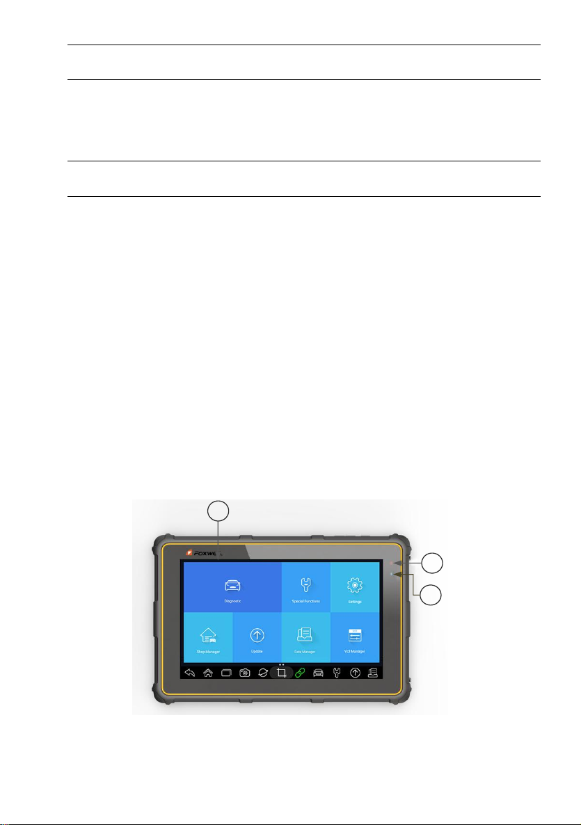
Figure 2-1Front View
1 8’’ LED IPS Capacitive Touch Screen - shows menus, test results and
operation tips.
Premier Diagnostic Platform i70Pro User's Manual V1.01
11
Page 12
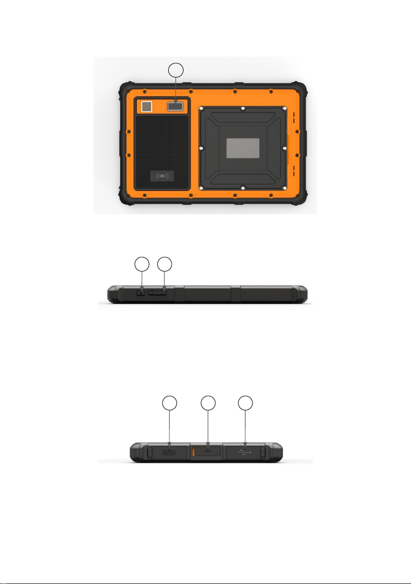
2 Power Indicator - indicates the power status of the scanner.
4
5
6
789
3 Charging Indicator - indicates the charging status of the scanner.
Figure 2-2 Back View
4 Rear-Facing Camera - takes pictures of VIN number, faulty parts and
plates and shoots test videos.
Figure 2-3 Top View
5 Power Switch - turns on the scanner, goes to sleep mode or wake up the
scanner from sleep mode, press and hold for 3 seconds for emergency
shutdown.
6 VOL + / VOL - press to adjust the volume.
Figure 2-4 Right View
7 USB Type-C Port - connects to wall plug to charge the scanner and can be
used to transfer data.
8 HDMI (high-definition multimedia interface) Port - outputs display of the
scanner for demonstration and training.
9 USB Port - provides USB connection with VCI dongle, oscilloscope, video
scope and other external storage devices.
Premier Diagnostic Platform i70Pro User's Manual V1.01
12
Page 13
IMPORTANT
2
4
3
1
5
Do not use solvents such as alcohol to clean display. Use a mild nonabrasive
detergent and a soft cotton cloth.
2.2 VCI Dongle Descriptions
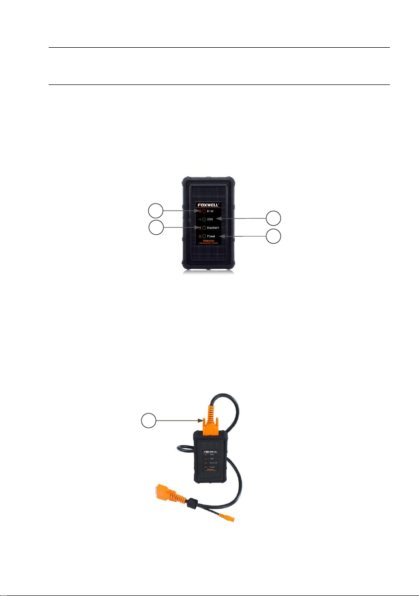
i70Pro connects to the vehicle and get data through the VCI dongle either by
Bluetooth or USB communication.
Figure 2-5 Front View of VCI dongle
1 Error Light - illuminates constantly when serious hardware failure occurs.
2 USB Light - turns green when the VCI dongle is properly connected and
communicating with the i70Pro tablet via USB cable.
3 Bluetooth Light - turns green when the VCI dongle is properly connected
with the i70Pro tablet via Bluetooth communication.
4 Power Light - turns to green when powered on.
Figure 2-6 Top View of VCI
Premier Diagnostic Platform i70Pro User's Manual V1.01
13
Page 14

5 Vehicle Data Connector - provides connection between vehicle and the
6
VCI dongle through the 16 pin diagnostic cable.
Figure 2-7 Bottom View of VCI
6 USB Port - provides USB connection between the VCI dongle and i70Pro
tablet.
Premier Diagnostic Platform i70Pro User's Manual V1.01
14
Page 15

2.3 Accessories
This section lists the accessories that go with the scanner. If you find any of
the following items missing from your package, contact your local dealer for
assistance.
Table 2-1 Accessories
Premier Diagnostic Platform i70Pro User's Manual V1.01
15
Page 16

2.4 Technical Specifications
Item
Description
Touch Screen
8’’ diagonal, daylight readable color LCD screen, 1280*800 pixel
Operation
System
Android
Processor
MT8163 (ARM Cortex, a53x4, 1.3GHz)
Memory
2GB DDR3L
SSD Hard drive
32GB
System Type
32-bit operating Systems, x64-based processor
Display
Backlit 1280*800 pixel 8” LED capacitive touch screen
Communication
interface
Built-in WIFI 802.11 b/g Wireless LAN
USB2.0 OTG/standard USB 2.0 HOST
Bluetooth 4.0 (10-20 m)
Camera
5 megapixels rear-facing
Built-in Battery
8000mAh, Lithium-polymer battery, chargeable via 5V/3AUSB power
supply
Protocols
ISO9141-2, ISO14230-2, ISO15765-4, K/L lines, Double K Line
SAE-J1850 VPW, SAE-J1850PWM, CAN ISO 11898, High-speed,
Middle-speed, Lows-peed and Single wire CAN, KW81, KW82, GM
UART, UART Echo Byte Protocol, Honda Diag-H Protocol, TP2.0, TP1.6,
SAE J1939, SAE J1939, SAE J1708, Fault-Tolerant CAN
Dimensions
230*155*21mm (L*W*H)
Table 2-2 Technical Specifications
3 Getting Started
This section describes how to power on/off the scanner, provides brief
introductions of applications loaded on the scanner and display screen layout
of the scan tool.
3.1 Powering up the Scanner
Before using the i70Pro applications (including updating the scanner), please
make sure to provide power to the scanner.
The unit operates on any of the following sources:
● Internal Battery Pack
● External Power Supply
Premier Diagnostic Platform i70Pro User's Manual V1.01
16
Page 17
3.1.1 Internal Battery Pack
The i70Pro tablet can be powered with the internal rechargeable battery. The
fully charged battery is capable of providing power for 14 hours of continuous
operation.
NOTE
Please turn off the tablet to save power when not use.
3.1.2 External Power Supply
The tablet can also be powered from a wall socket using the USB charging
adapter. The tablet charges its internal battery pack through USB Type-C
cable.
3.2 Shutting Down the Scanner
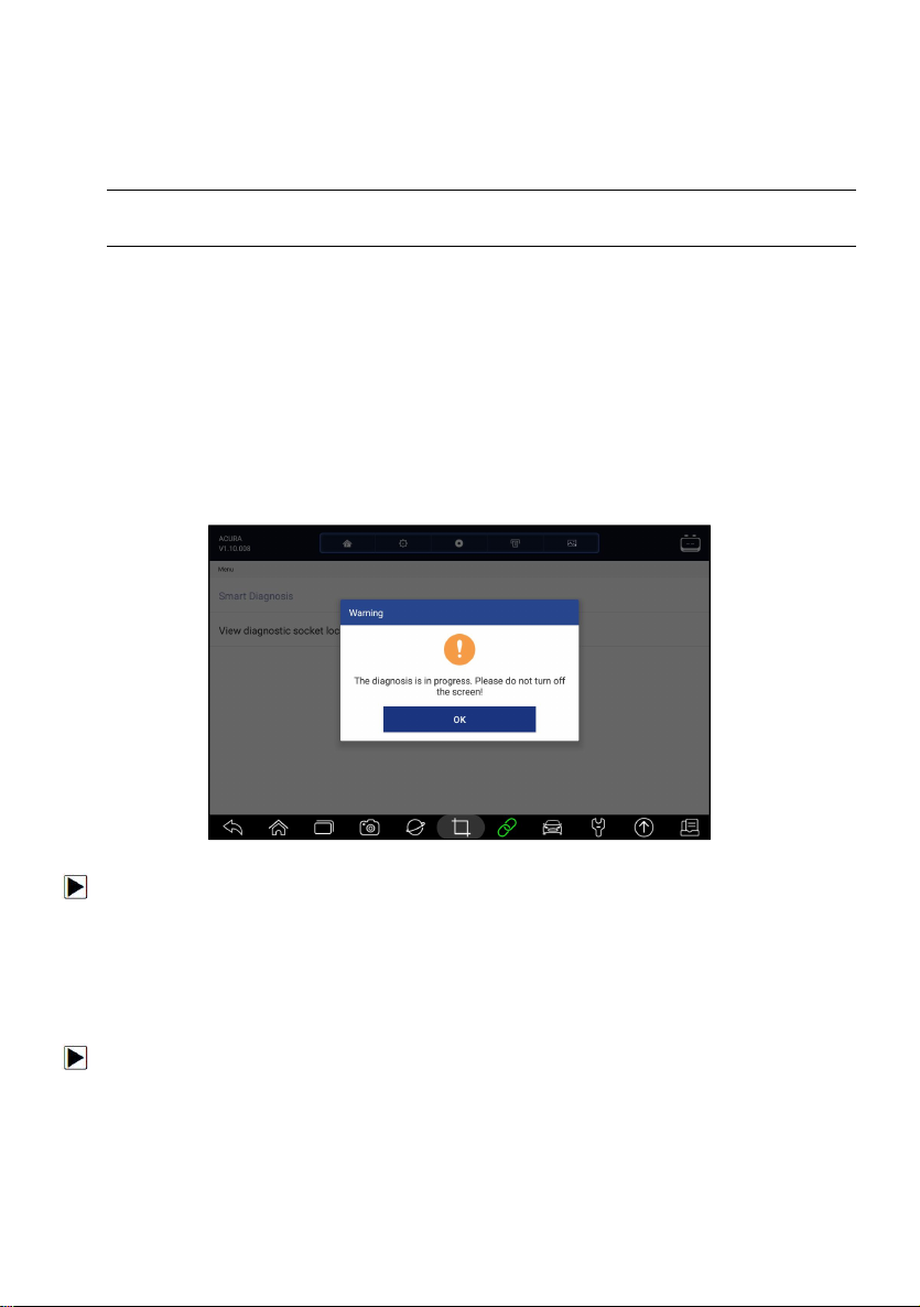
All vehicle communication must be terminated before shutting down the
scanner. Exit the Diagnostic application before powering down.
Figure 3-1 Power-off Prompt Screen
To shut down the scanner:
1. Press and hold the Power button of the i70Pro for 5 seconds.
2. Click the Power off to shut down or Reboot to restart.
3.3 Establishing Vehicle Communication
To establish communication with i70Pro:
1. Connect the VCI dongle to the vehicle’s DLC for both communication and
power source.
2. Connect the VCI dongle to the i70Pro tablet via Bluetooth or USB
connection.
Premier Diagnostic Platform i70Pro User's Manual V1.01
17
Page 18

Figure 3-2 Sample Bluetooth Communication Screen
Figure 3-3 Sample USB Communication Screen
Please refer to Chapter 3.3.1.1about the details of how to connect via
Bluetooth and Chapter 3.3.1.2 about the details of how to connect via
USB cable.
3. Check the VCI Indicator status at the toolbar. If the button turns to green,
the i70Pro is ready to start vehicle diagnosis.
3.3.1 VCI Connection
The VCI dongle supports two ways of communication with the i70Pro tablet:
● Bluetooth Communication
● USB Communication
3.3.1.1 Bluetooth Communication
Bluetooth communication is recommended. The working range for Bluetooth
communication is about 10-20m, providing easy connection to vehicles in any
location throughout the shop.
Premier Diagnostic Platform i70Pro User's Manual V1.01
18
Page 19
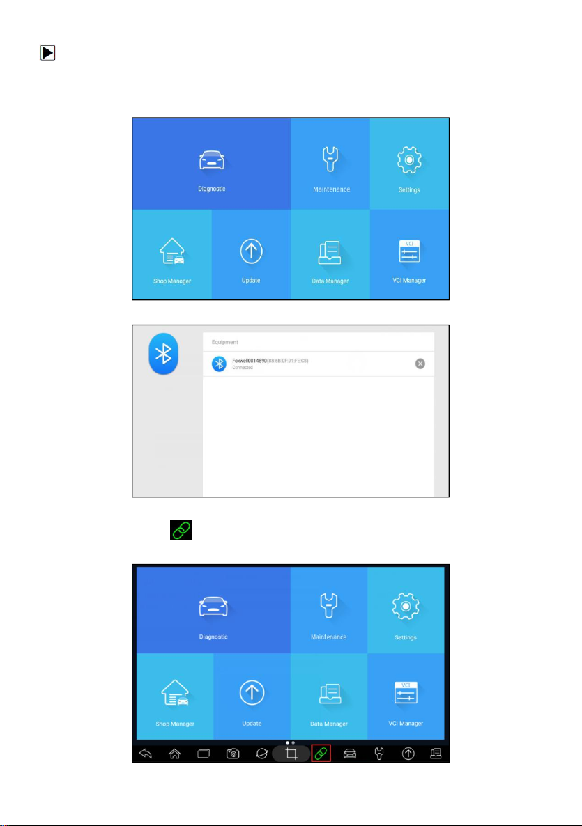
To build Bluetooth connection:
1. Power up the tablet.
2. Go to VCI Manager and then Bluetooth. Click Connect and the VCI dongle
will connect to the tablet automatically.
Figure 3-4 Sample VCI Manager Screen
Figure 3-5 Sample Bluetooth Connection Screen
3. Check if the button at the toolbar turns to green. If yes, it means it’s
ready to start diagnosis.
Premier Diagnostic Platform i70Pro User's Manual V1.01
19
Page 20
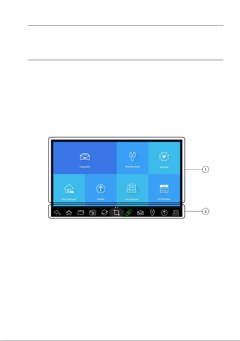
Figure 3-6 Sample VCI Indicator Status Screen
NOTE
If the VCI Indicator isn’t green, it indicates that the signal strength of the
transmitter is too weak to be detected. In this case, try to get closer to the
device, or check the connection of VCI dongle, and remove all possible
objects that cause signal interference
3.3.1.2 USB Communication
The USB connection is a simple and quick way to establish communication
between the tablet and the VCI dongle. Connect the dongle and tablet with
the USB Type B cable, and the VCI Indicator will turn green, indicating the
dongle has connected to the tablet.
3.4 Screen Layout of Home Screen
When the tablet boots up, press the i70Pro desktop icon to launch the
diagnostic application.
1. Application Menu
2. Navigation Toolbar
Premier Diagnostic Platform i70Pro User's Manual V1.01
Figure 3-7 Sample Home Screen
20
Page 21
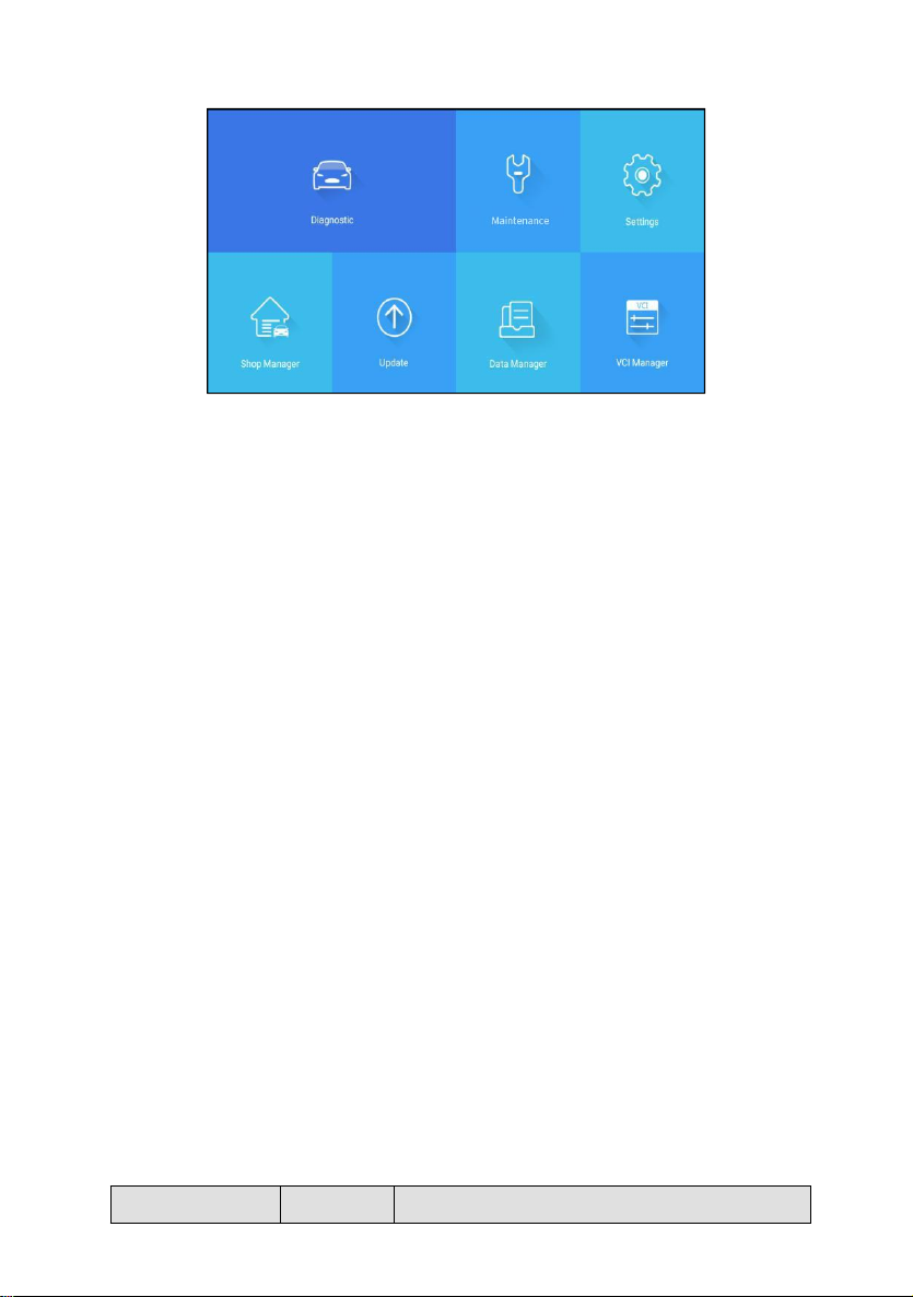
3.4.1 Application Menu
Name
Button
Description
Figure 3-8 Sample Application Screen
This section briefly introduces the applications that are preloaded into the
scanner:
● Diagnostic - leads to test screens for diagnostic trouble code information,
live data, active tests, coding and etc.
● Maintenance - leads to screens for the most commonly used service
functions like Oil light reset, EPB, BRT, DPF and etc.
●
Settings - leads to screens for adjusting default settings to meet your own
preference and view information about the scanner.
● Shop Manager - allows the technicians to manage the workshop
information and vehicle test records.
● Data Manager - leads to screens for saved screenshots, pictures and test
reports, and playing back live data, as well as debug logging data.
●
Update - leads to screens for Foxwell ID registration and updating the
scanner.
● VCI Manager - leads to screens for making Bluetooth pairing of VCI
dongle and tablet, updating the VCI firmware and binding/unbinding VCI
dongle.
●
My Account - displays your Foxwell ID information like registered
products and personal information and allows for sending us feedbacks
about the scanner.
● Remote Control - leads to TeamViewer to get remote support from
Foxwell team.
● Technical Data - provides access to repair data like HaynesPro.
3.4.2 Navigation Toolbar
Operations of the buttons located on toolbar are described in the table
below:
Premier Diagnostic Platform i70Pro User's Manual V1.01
21
Page 22
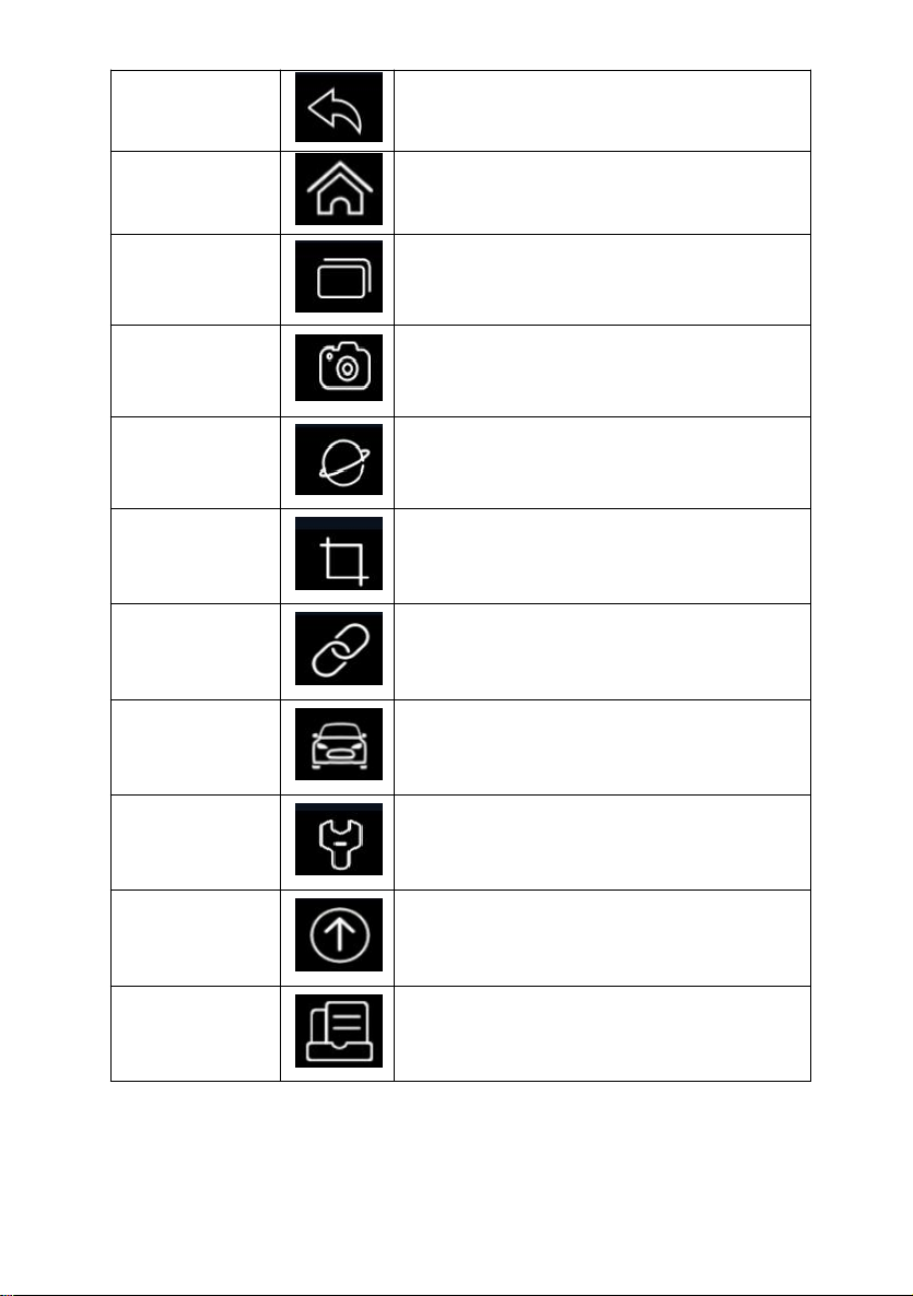
Table 3-1 Tool Bar
Back
Back to the previous screen.
Home
Returns to Home screen of Android System.
Multitask
Allows for browsing, switching and closing active
applications.
Camera
Takes a photo or picture.
Browser
Opens the built-in browser.
Screenshot
Captures screens.
VCI Indicator
Shortcut for VCI Manager menu from any screen of
the tablet; also it is the indicator of Bluetooth/USB
connection status.
Diagnostic
Shortcut for Diagnostic menu from any screen of
the tablet.
Maintenance
Shortcut for Maintenance menu from any screen of
the tablet.
Update
Shortcut for Update menu from any screen of the
tablet.
Data Manager
Shortcut for Data Manager menu from any screen
of the tablet.
Premier Diagnostic Platform i70Pro User's Manual V1.01
22
Page 23
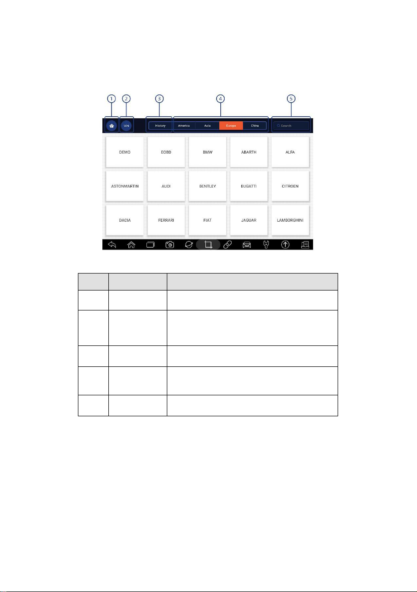
3.4.3 Diagnostic Menu
No.
Name
Description
1
Home
Back to the Application Menu.
2
VIN
Shortcut for VIN reading menu, which
typically includes Automatic Read, Scan VIN
and Manual Entry.
3
History
Displays the tested vehicle records.
4
Area
Displays car makes from different origins like
America, Asia, Europe and Chinese.
5
Search
Lets you search a vehicle make quickly.
Touch Diagnostic at the i70Pro application menu, and the Diagnostic menu
will display. The operations of the buttons on Diagnostic menu are described
in the below table.
Figure 3-9 Sample Diagnostic Menu Screen
Table 3-2 Diagnostic Menu Title Bar
4 Vehicle Identification
This section illustrates how to use the scanner to identify the specifications of
the vehicle under test.
The vehicle identification information presented is provided by the ECM of
the vehicle being tested. Therefore, certain attributes of the test vehicle must
be entered into the scan tool to ensure the data displays correctly. The
vehicle identification sequence is menu driven. Simply follow the screen
Premier Diagnostic Platform i70Pro User's Manual V1.01
23
Page 24
prompts and make a series of choices. Each selection you make advances
you to the next screen. Exact procedures may vary somewhat by vehicle.
It typically identifies a vehicle by any of the following means:
●
VIN Reading
● Manual Selection
● History Records
NOTE
Not all identification options listed above are applicable to all vehicles.
Available options may vary by vehicle manufacturer.
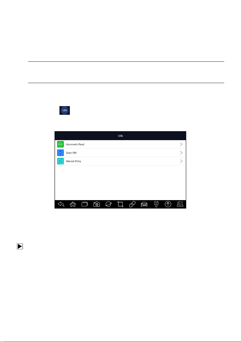
4.1 VIN Reading
VIN button on the title bar is a shortcut for VIN reading menu, which
includes Automatic Read, Scan VIN and Manual Entry, eliminating the need
for navigating through complicated car identification process.
Figure 4-1 Sample VIN Hotkey Screen
4.1.1 Automatic Read
Automatic Read allows to identify a vehicle by automatically reading the
vehicle identification number (VIN).
To identify a vehicle by Automatic Read:
1. Select Diagnostic from home screen of the i70Pro application.
2. Click VIN and choose Automatic Read from the option list.
Premier Diagnostic Platform i70Pro User's Manual V1.01
24
Page 25
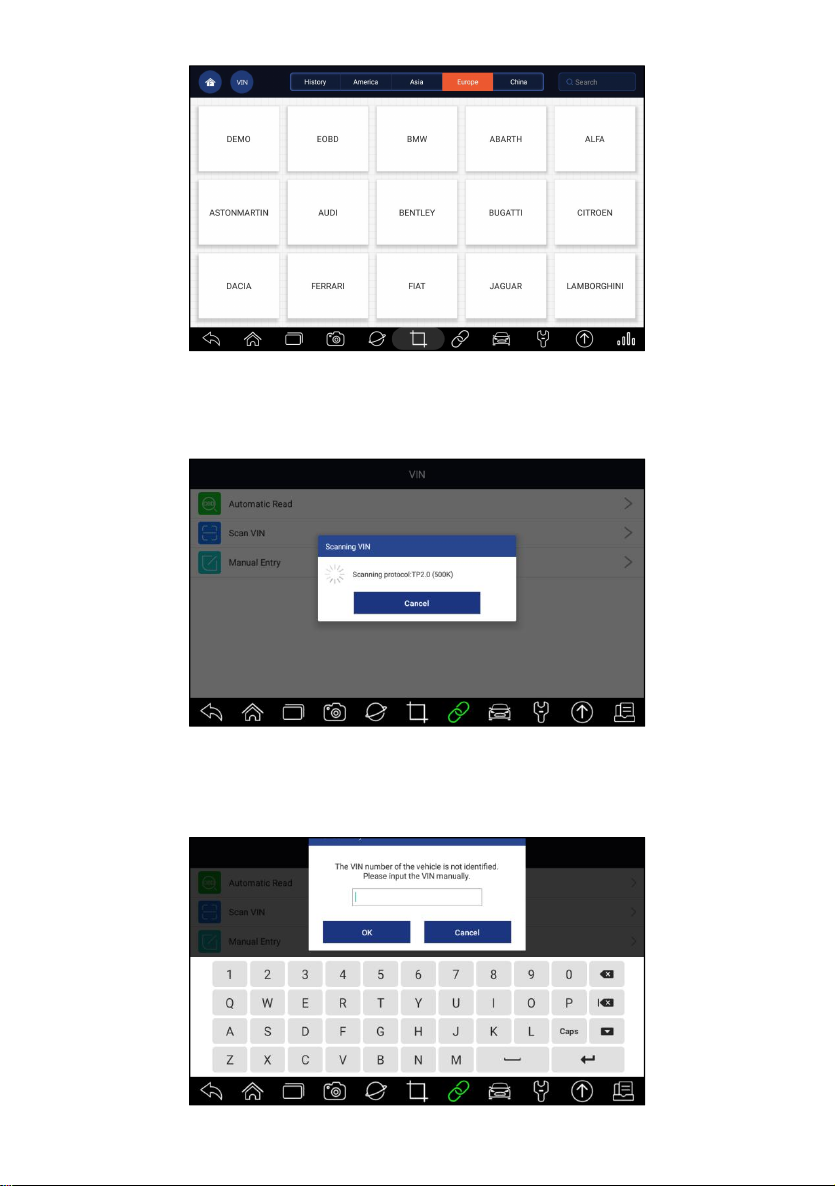
Figure 4-2 Sample Automatic Read Screen
3. When the scan tool builds connection with the vehicle, the VIN number
displays. If the Vehicle Specification or VIN code is correct, press the OK
to continue.
Figure 4-3 Sample Automatic Read Screen
4. If it takes too long to get the VIN code, press Cancel to stop and input the
VIN manually. Or if failed to identify the VIN, please input the VIN
manually or click Cancel to quit.
Premier Diagnostic Platform i70Pro User's Manual V1.01
25
Page 26
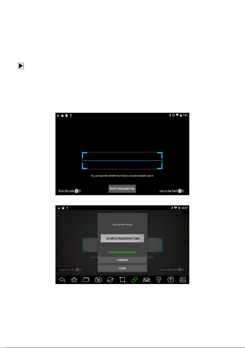
Figure 4-4 Sample Manual Entry Screen
4.1.2 Scan VIN
Scan VIN allows identifying a vehicle by scanning the VIN plate of the vehicle,
barcode, QR code or photo recognition.
4.1.2.1 Scan VIN Plate
To identify a vehicle by Scan VIN Plate:
1. Select Diagnostic from home screen of the i70Pro application.
2. Click VIN button and choose Scan VIN from the option list.
3. Find the VIN plate of your car, and put the VIN number into the scanning
box. The VIN number displays with a successful scan. If the Vehicle
Specification or VIN code is correct, press the Confirm to continue. If
incorrect, you are allowed to modify VIN number manually.
Figure 4-5 Sample Scan VIN Screen
Figure 4-6 Sample VIN Confirmation Screen
Premier Diagnostic Platform i70Pro User's Manual V1.01
26
Page 27
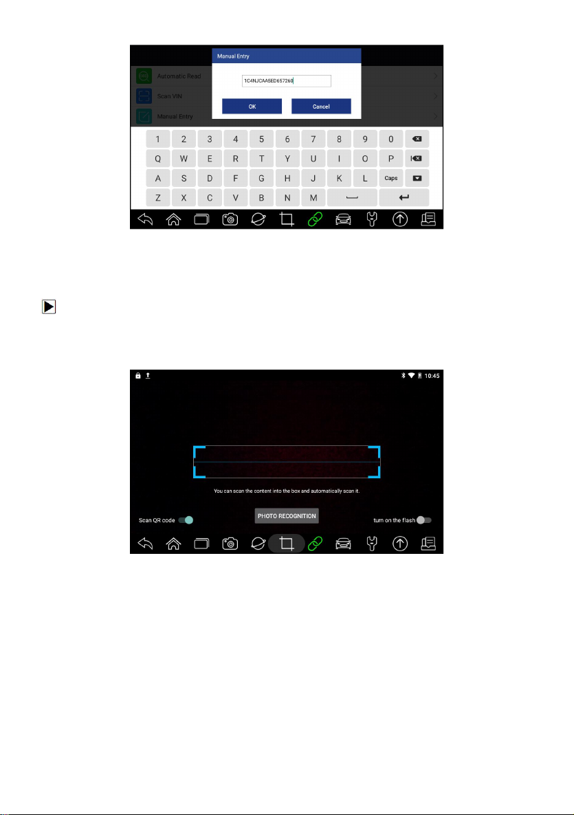
Figure 4-7 Sample Modify VIN Screen
4. If failed, please click Close to quit and input the VIN manually.
4.1.2.2 Scan Barcode/QR Code of VIN
To identify a vehicle by Scan QR Code:
1. Select Diagnostic from home screen of the i70Pro application.
2. Click VIN button, choose Scan VIN from the option list and enable Scan
QR Code at the lower left part of the screen.
Figure 4-8 Sample Scan QR Code Screen
3. Find the VIN QR code or bar code of your car, and put the code into the
scanning box. The VIN number displays with a successful scan. If the
Vehicle Specification or VIN code is correct, press the Confirm to continue.
If incorrect, you are allowed to modify VIN number manually. The scan box
can be zoomed in or zoomed out.
Premier Diagnostic Platform i70Pro User's Manual V1.01
27
Page 28
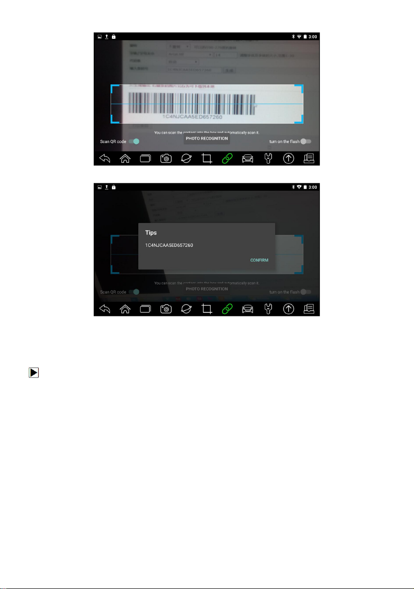
Figure 4-9 Sample Scan QR Code Screen
Figure 4-10 Sample VIN Confirmation Screen
4. If failed, please click Close to quit and input the VIN manually.
4.1.2.3 Photo Recognition
To identify a vehicle by Photo Recognition:
1. Select Diagnostic from home screen of the i70Pro application.
2. Click VIN button and choose Scan VIN from the option list.
3. Find the VIN plate, QR code or barcode of your car, and put the content
number into the scanning box. Then click Photo Recognition button on
the lower middle screen. The VIN number displays with a successful scan.
If the Vehicle Specification or VIN code is correct, press the Confirm to
continue. If incorrect, you are allowed to modify VIN number manually.
Premier Diagnostic Platform i70Pro User's Manual V1.01
28
Page 29
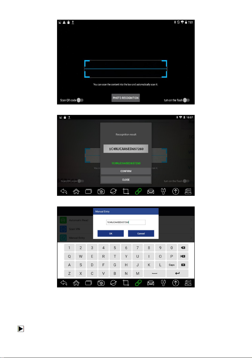
Figure 4-11 Sample Photo Recognition Screen
Figure 4-12 Sample VIN Confirmation Screen
Figure 4-13 Sample Modify VIN Screen
4. If failed, please click Close to quit and input the VIN manually.
4.1.3 Manual Entry
Manual Entry allows to identify a vehicle by inputting VIN manually.
To identify a vehicle by Manual Entry:
Premier Diagnostic Platform i70Pro User's Manual V1.01
29
Page 30
1. Select Diagnostic from home screen of the i70Pro application.
Name
Button
Description
Home
Back to the Application Menu.
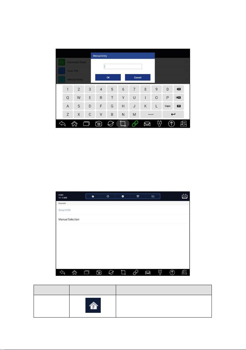
2. Click VIN and choose Manual Entry from the option list.
3. Press Keyboard button to input a valid VIN code and press OK to
continue.
Figure 4-14 Sample Manual Entry Screen
4.2 Manual Selection
Select vehicle brand you are to test, and two ways of getting to the diagnostic
operations are available.
●
Smart VIN
●
Manual Selection
Premier Diagnostic Platform i70Pro User's Manual V1.01
Figure 4-15 Sample Vehicle Entry Screen
30
Page 31
Settings
A shortcut for Settings menu.
Data Logging
Records the communication data between
the scan tool and the vehicle to help with
troubleshooting of diagnostic failures.
Print
Print the test data and report.
Screenshot
Takes screenshot of test data or report and
save them for later analysis.
Table 4-1Title Bar
4.2.1 Smart VIN
Smart VIN allows to identify a vehicle by automatically reading the vehicle
identification number (VIN).
To identify a vehicle by Smart VIN:
1. Select Diagnostic from home screen of the i70Pro application.
2. A screen with vehicle manufacturers displays. Select the area where the
vehicle manufacturer from. A menu of all vehicle manufacturers displays.
Or tap the Search box to search the car you are to test.
Figure 4-16 Sample Vehicle Selection Screen
3. Choose SmartVIN option to start reading the VIN automatically.
Premier Diagnostic Platform i70Pro User's Manual V1.01
31
Page 32
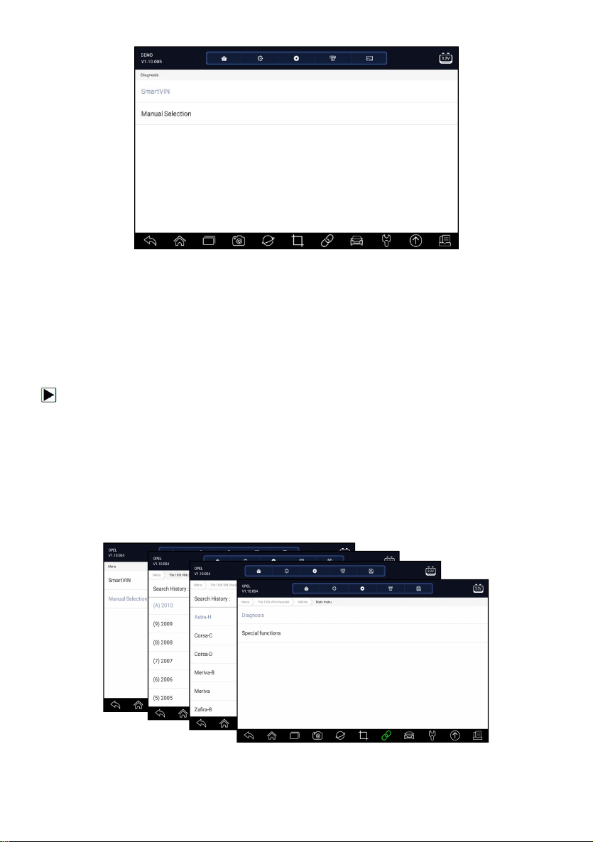
Figure 4-17 Sample Smart VIN Screen
4. After the scan tool builds connection to the vehicle, the VIN number
displays. If the Vehicle Specification or VIN code is correct, press the OK
to continue. If incorrect, please enter a valid VIN number manually.
4.2.2 Manual Vehicle Selection
Manual Selection identifies a vehicle by making several selections
according to certain VIN characters, such as model year, and engine type.
To identify a vehicle by manual vehicle selection:
1. Select Diagnostic from home screen of the i70Pro application.
2. A screen with vehicle manufacturers displays. Select the area where the
vehicle manufacturer is from. A menu of all vehicle manufacturers displays.
Or tap the Search box to search the car you are to test.
3. Choose Manual Selection option from the list.
4. On each screen that appears, select the correct option until the complete
vehicle information is entered and the menu of controller selection
displays.
Figure 4-18 Sample Manual Vehicle Selection Screen
Premier Diagnostic Platform i70Pro User's Manual V1.01
32
Page 33
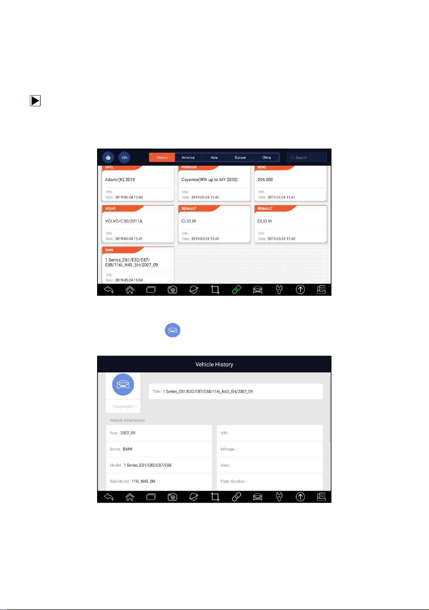
4.3 Vehicle History
Vehicle History keeps records of tested vehicles and allows restarting the
diagnosis of a vehicle without the need to do vehicle identification again.
To identify a vehicle by Vehicle History:
1. Select Diagnostic from home screen of the i70Pro application.
2. Select History button at the top of the diagnostic page and the diagnostic
records will display.
Figure 4-19 Sample History Record Screen
3. Choose the vehicle model you want to test from the list.
4. Click the Diagnostic button at the tested vehicle information page
and then answer Yes to go to system selection page.
Figure 4-20 Sample History Record Screen
Premier Diagnostic Platform i70Pro User's Manual V1.01
33
Page 34
5 Diagnosis
This section illustrates how to use the scanner to read and clear diagnostic
trouble codes, view live data readings and ECU information on controllers
installed, perform special functions such as actuation and coding, and
perform vehicle services and maintenance on Asia, European and USA
vehicle brands.
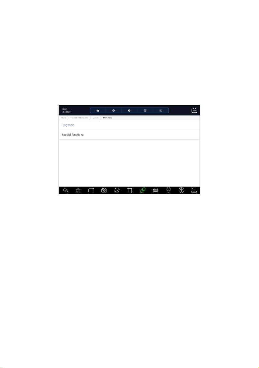
When you have completed the identification of vehicle, the main menu
displays. Menu options typically include:
● Diagnosis
● Special Functions
Figure 5-1 Sample Main Menu Screen
5.1 Control Module Selection
When you completed the identification of vehicle, you have to identify the
control modules installed in the vehicle. There are two ways to identify the
controllers installed in a car:
● Quick Scan
●
Control Modules
Premier Diagnostic Platform i70Pro User's Manual V1.01
34
Page 35
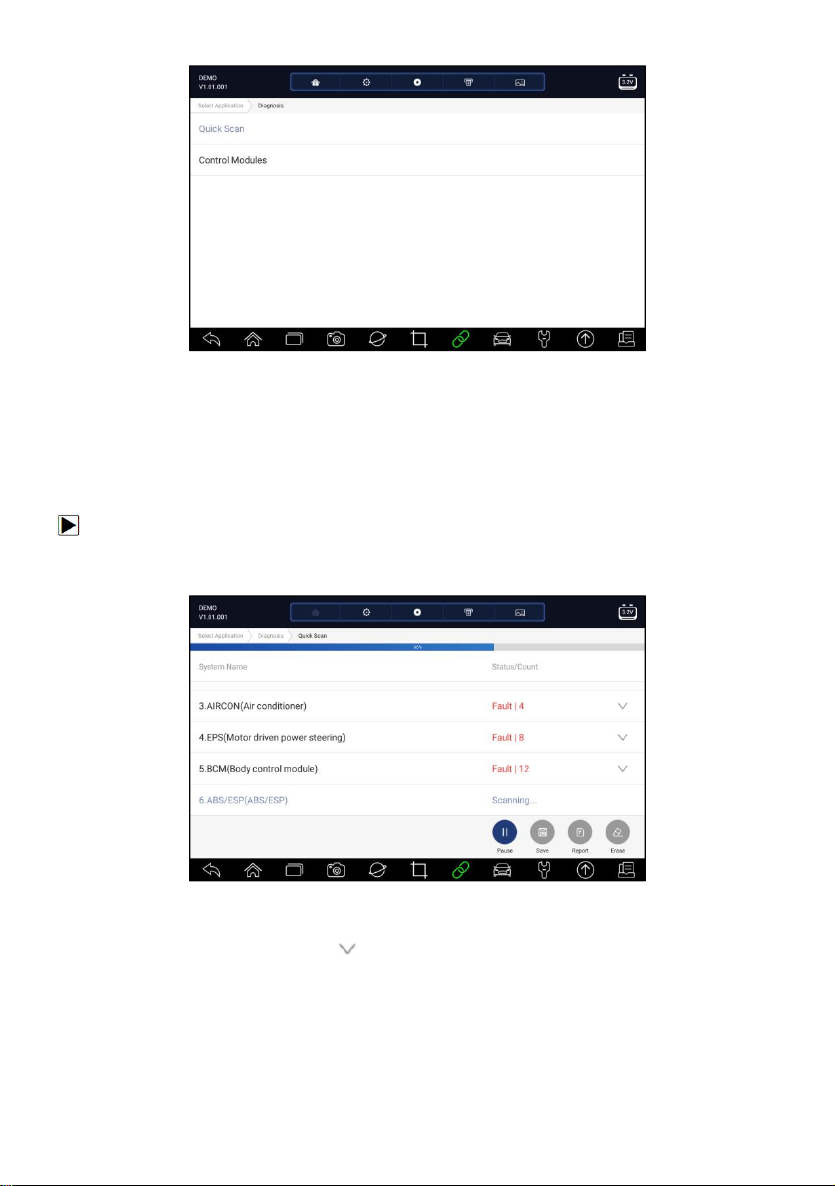
Figure 5-2 Sample Diagnosis Screen
5.1.1 Quick Scan
Quick Scan performs an automatic system test to determine which control
modules are installed on the vehicle and provides diagnostic trouble codes
(DTCs) overview. Depending on the number of control modules, it may take a
few minutes to complete the test.
To perform an automatic system scan:
1. Press Quick Scan option to start.
2. To pause the scan, press the Pause button on the screen.
Figure 5-3 Sample Quick Scan Screen
3. At the end of successful automatic controller scan, a menu with a list of
DTC displays and click button to the right to view DTC descriptions.
Premier Diagnostic Platform i70Pro User's Manual V1.01
35
Page 36
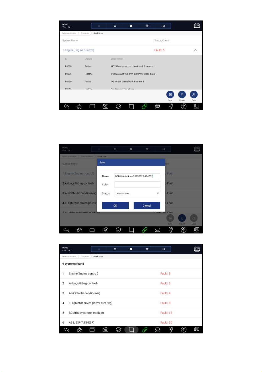
Figure 5-4 Sample Quick Scan Complete Screen
4. Press Report to create an overview of installed control units and their
system status, or press Save to save the report. Press Erase to clear the
information.
Figure 5-5 Sample DTC Save Screen
Figure 5-6 Sample Report Screen
Premier Diagnostic Platform i70Pro User's Manual V1.01
36
Page 37
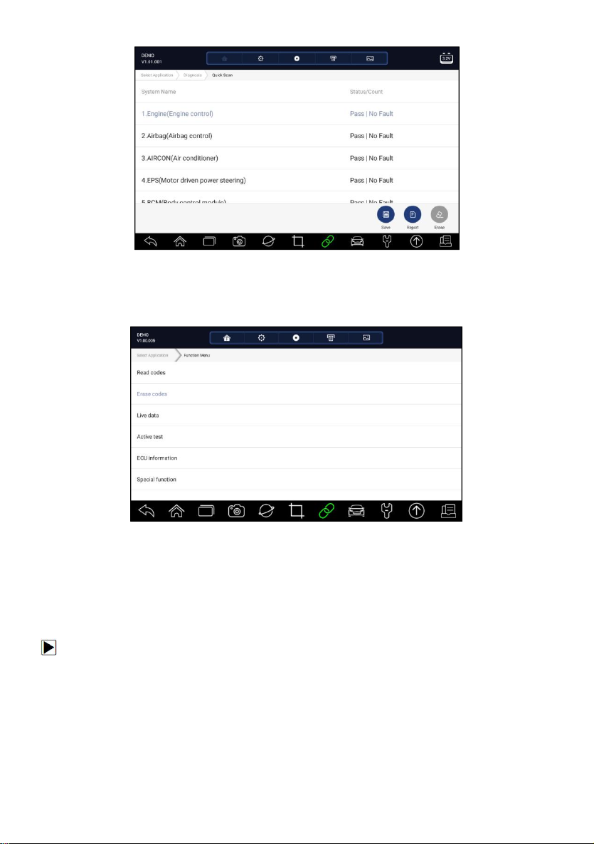
Figure 5- 7 Sample Erase Screen
5. When running auto scanning, you can press Pause and select the system
you would like to test. When the scanner has established connection with
the vehicle, the Function Menu displays.
Figure 5-8 Sample Function Menu Screen
5.1.2 Control Modules
Control Modules displays all controllers available of the vehicle
manufacturer. The controllers listed on the menu do not mean that they are
installed on the vehicle. It is useful for technicians who are familiar with the
vehicle specifications.
To select a system to test:
1. Press Control Modules from the menu and a controller menu displays.
Premier Diagnostic Platform i70Pro User's Manual V1.01
37
Page 38
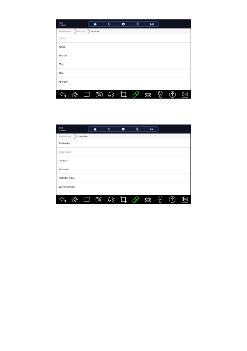
Figure 5-9 Sample Control Modules Screen
2. Select a system to test. When the scanner has established connection
with the vehicle, the Function Menu displays.
Figure 5-10 Sample Function Menu Screen
5.2 Diagnostic Operations
After a system is selected and the scanner establishes communication with
the vehicle, the Function Menu displays. Generally the menu options are:
●
Read Codes
●
Clear Codes
● Live Data
● Active Test
● ECU Information
●
Special Functions
NOTE
Not all function options listed above are applicable to all vehicles. Available
options may vary by the year, model, and make of the test vehicle.
Premier Diagnostic Platform i70Pro User's Manual V1.01
38
Page 39
5.2.1 Read Codes
Read Codes menu lets you read trouble codes found in the control unit.
There are 4 types of code status:
●
Present/Permanent/Current
●
Pending
● History
● Self-diagnostic
Present/Permanent/Current codes stored in a control module are used to
help identify the cause of a trouble or troubles with a vehicle. These codes
have occurred a specific number of times and indicate a problem that
requires repair.
Pending codes are also referred to as maturing codes that indicate
intermittent faults. If the fault does not occur within a certain number of drive
cycles (depending on vehicle), the code clears from memory. If a fault occurs
a specific number of times, the code matures into a DTC and the MIL
illuminates or blinks.
History codes are also referred to as past codes that indicate intermittent
DTCs that are not currently active. Code history is number of engine starts
since DTC(s) were first detected (to see if they are current or intermittent).
Self-diagnostic lets you manually activate system tests that check for DTCs.
Usually it includes a KOEO (Key-on, engine-off) test and a KOER (key-on,
engine-running) test.
To read codes from a vehicle:
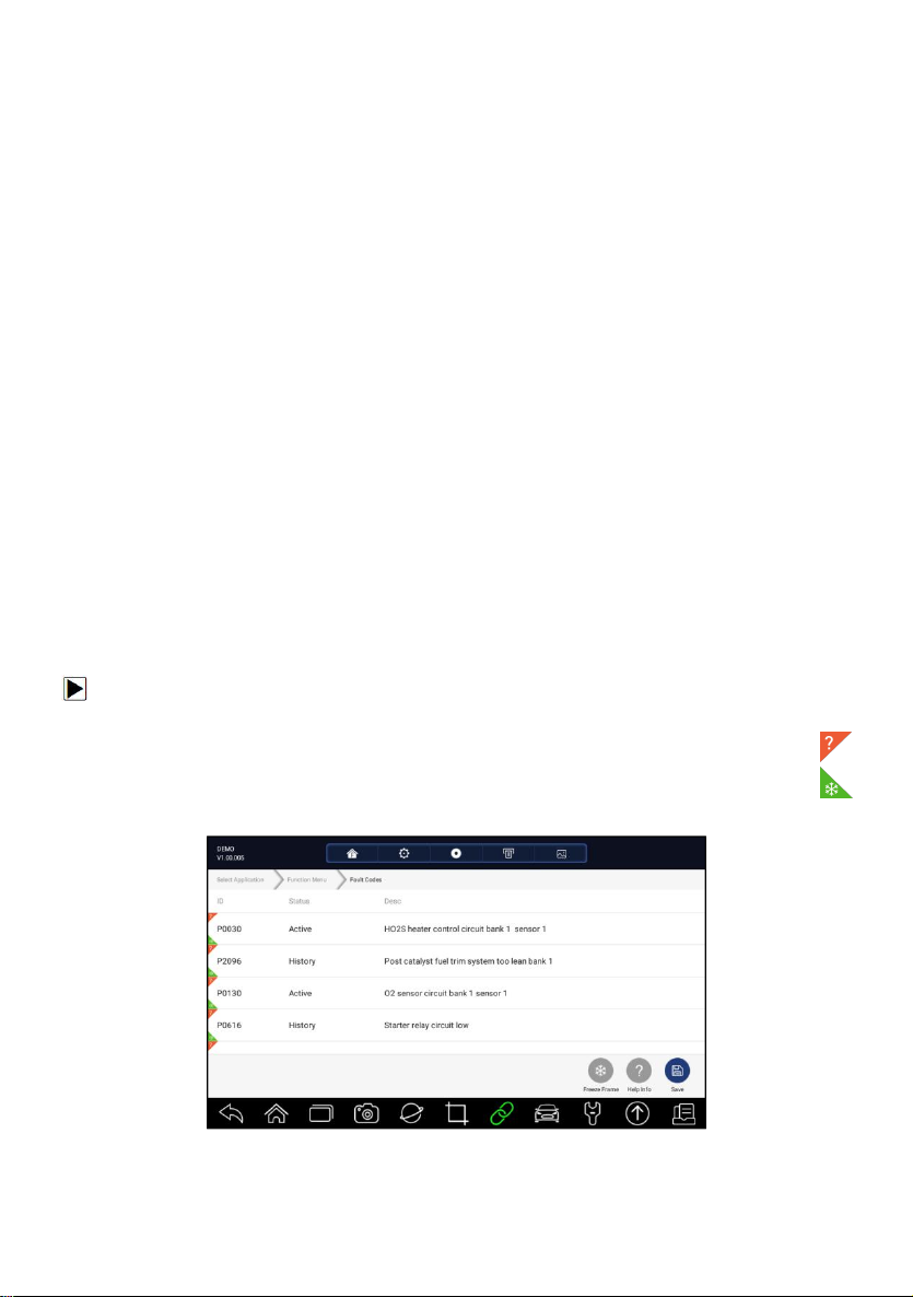
1. Press Read Codes from Select Diagnostic Function menu. A code list
including code number and its description displays. The red icon
means there is help information available for the code. The green icon
means there is freeze frame available.
Figure 5-11 Sample Trouble Code Screen
●
Freeze Frame- select one fault code from the code list and click Freeze
Frame button on the screen. The screen will display freeze frame data, a
Premier Diagnostic Platform i70Pro User's Manual V1.01
39
Page 40
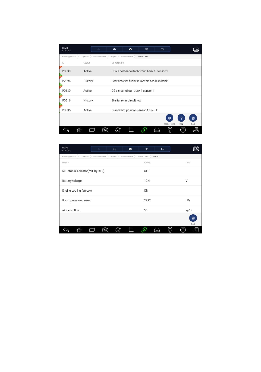
snapshot of critical vehicle operating conditions automatically recorded by
the on-board computer at the time of the DTC set. It is a good function to
help determine what caused the fault.
Figure 5-12 Sample Trouble Code Screen
Figure 5-13 Sample Freeze Frame Screen
●
Help - select one fault code from the code list and click Help button on the
screen. The screen will display the detailed descriptions about the fault
code and repair guide.
Premier Diagnostic Platform i70Pro User's Manual V1.01
40
Page 41
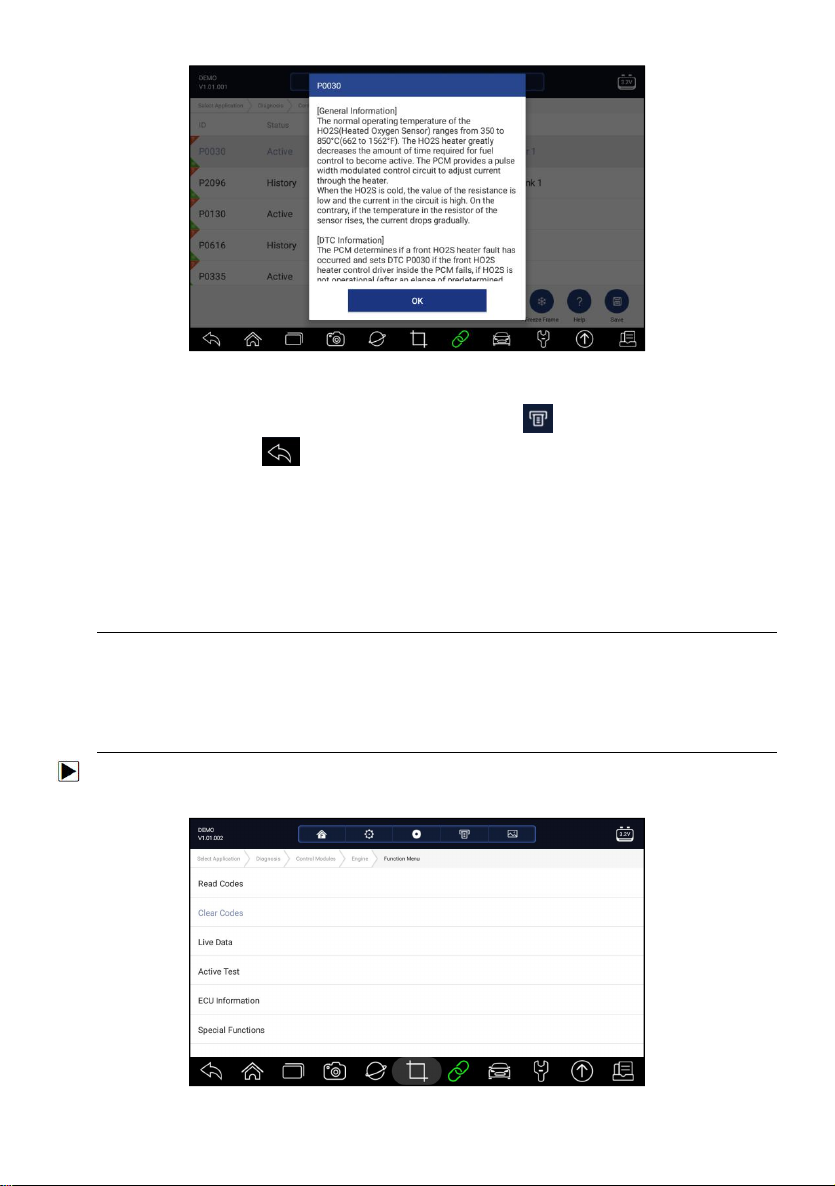
Figure 5-14 Sample DTC Help Screen
2. Slide up and down to view additional information when necessary.
3. Press Save to store DTC information. Press to print the information if
need be. Press to exit.
5.2.2 Clear Codes
Clear Codes menu lets you to clear all current and stored DTCs from a
selected control module. Also it erases all temporary ECU information,
including freeze frame, so make sure that the selected system is completely
checked and serviced by technicians and no vital information will be lost
before clearing codes.
NOTE
●
To clear codes, make sure that the ignition key is switched to ON with the
engine off.
● Clear Codes does not fix the problem that caused the fault! DTCs should
only be erased after correcting the condition(s) that caused them.
To clear codes:
1. Press Clear Codes from Select Diagnostic Function menu.
Figure 5-15 Sample Function Menu Screen
Premier Diagnostic Platform i70Pro User's Manual V1.01
41
Page 42
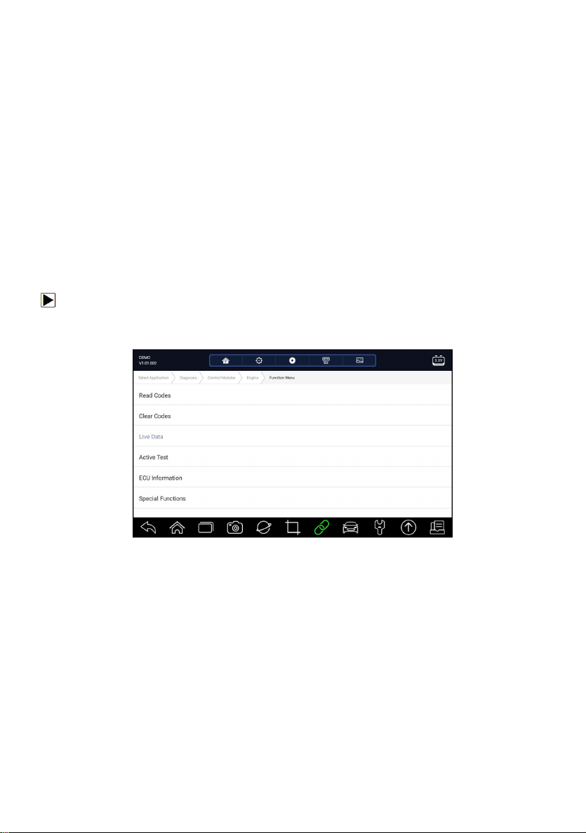
2. Follow the on-screen instructions and answer questions about the vehicle
being tested to complete the procedure.
3. Check the codes again. If any codes remain, repeat the Clear Codes
steps.
5.2.3 Live Data
Live Data menu lets you view real time PID data in text and plot formats,
learn good sensor data and compare them with faulty data, and record live
data from a selected vehicle electronic control module.
Menu options typically include:
●
All Data
●
Custom List
5.2.3.1 All Data
All Data menu lets you view all live PID data from a selected control module.
To view all live PID data:
1. Press Live Data from Select Diagnostic Function menu to display the live
data menu.
Figure 5-16 Sample Function Menu Screen
2. Press All Data from the menu to display the data stream screen. All
readings will be displayed in text format by default.
Premier Diagnostic Platform i70Pro User's Manual V1.01
42
Page 43
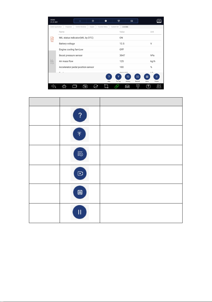
Figure 5-17 Sample Live Data Screen
Name
Button
Description
Help
To provide help information of a PID
To Top
To move a data line to the top of Data List
screen
History
To view the previous live data records or
test reports
Record
To make record of live data
Save
To save live data of current frame
Pause
To stop recording live data
Table 5-1 Live Data Screen Button Screen
● Learn Mode: gives you the ability to learn good live sensor data values
during idle, KEKO, acceleration, deceleration, part load and heavy load
on each vehicle comes into your shop and records them for future
reference. Click the dropdown list at the upper left of the screen to enter to
choose a working condition to learn.
Premier Diagnostic Platform i70Pro User's Manual V1.01
43
Page 44
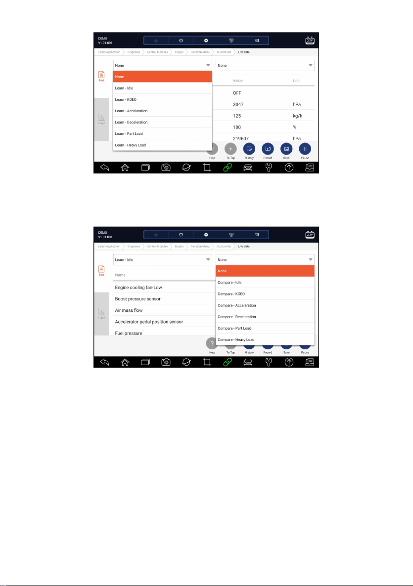
Figure 5-18 Sample Learn Mode Screen
●
Compare Mode - If that vehicle comes in is with a problem, you can easily
compare the faulty sensor and parameter readings to the good readings,
and you will be alarmed when a faulty sensor reading is detected.
Figure 5-19 Sample Live Data Screen
3. Swipe the screen up and down to view additional information when
necessary.
4. To move a data line to the top of Data List screen, just tap the line to select
and then press the button To Top. To view data records or test reports,
and press the button History. To make records of live data, just tab the
button Record, and press Pause to stop recording at any time. To save
the data, tap the Save icon.
5. To view live PID in graph format, press the tab Graph, and the plot
displays. To view another PID plot, tab the name of a plot and a list of
available PIDs display. Select one from the dropdown box and the plot
changes to the newly selected PID.
Premier Diagnostic Platform i70Pro User's Manual V1.01
44
Page 45
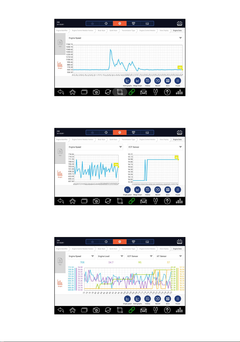
Figure 5-20 Sample PID Graph Screen
● Multi-graphs: displays the parameters in waveform graphs, giving you
the ‘real picture’ of what’s going on in the vehicle. You can view up to 4
parameter graphs simultaneously.
Figure 5-21 Sample Multi-graphs Screen
●
Merge Graph: merges multiple PID plots into one coordinate, so you can
easily see how they affect each other, providing you with the most
comprehensive and functional look at live data possible.
Figure 5-22 Sample Merge Graph Screen
Premier Diagnostic Platform i70Pro User's Manual V1.01
45
Page 46
5.2.3.2 Custom List
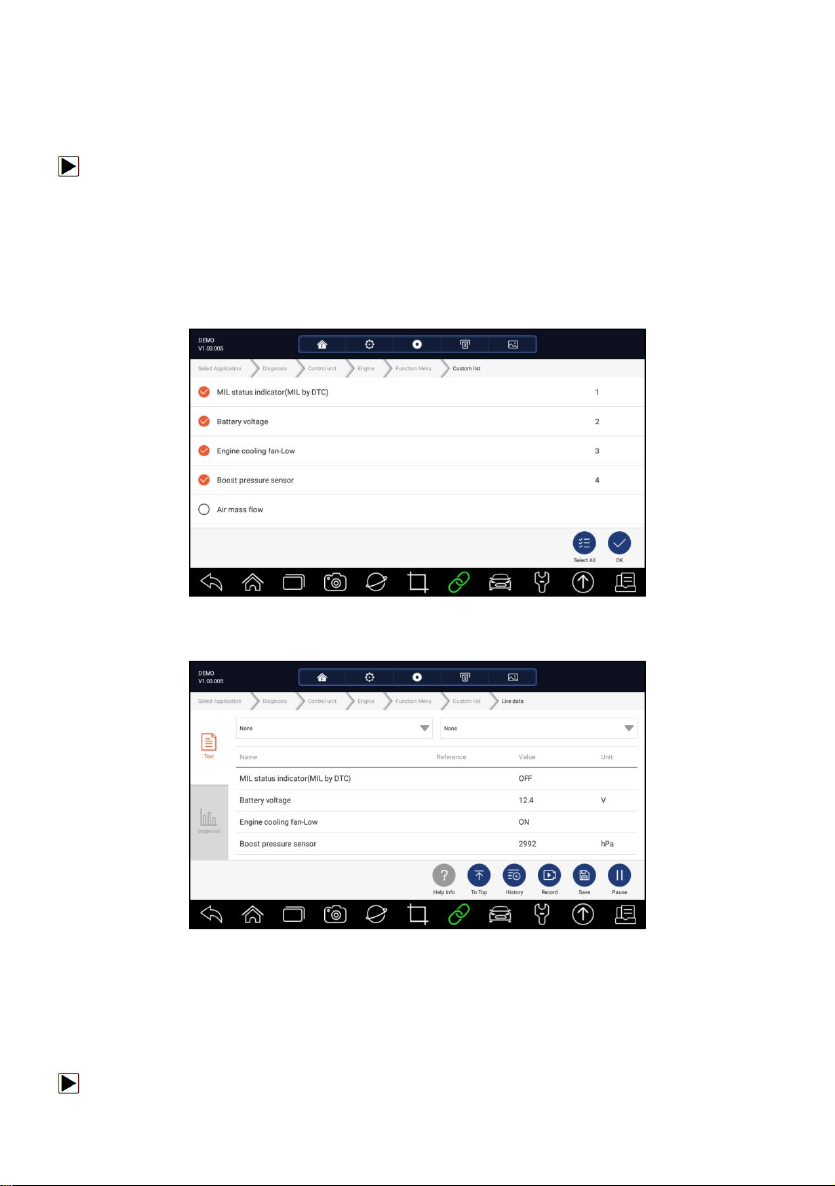
Custom List menu lets you to minimize the number of PIDs on the data list
and focus on any suspicious or symptom-specific data parameters.
To create a custom data list:
1. Press Custom List from the menu to display all available parameters from
the selected control module.
2. The custom data stream selection screen displays. Tap the lines you
wish to select.
3. To deselect an item, tap the line again. Alternatively, tap SELECT ALL or
CLEAR ALL to select or deselect all items at once.
Figure 5-23 Sample Custom List Selection Screen
4. Press OK to complete the selection, and all selected parameters display.
Figure 5-24 Sample Live Data Screen
5.2.4 ECU Information
ECU Information screen displays the identification data of the control
module under test, such as the control module identification string and the
control module coding.
To read ECU information:
Premier Diagnostic Platform i70Pro User's Manual V1.01
46
Page 47
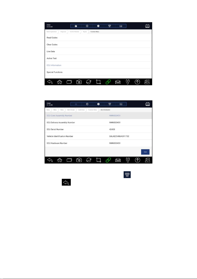
1. Press ECU Information from Select Diagnostic Function menu.
Figure 5-25 Sample Function Menu Screen
2. A screen with detailed information of the selected control module displays.
Figure 5-26 Sample ECU Information Screen
3. Press Save to store ECU information. Press to print the information if
need be. Press to exit.
5.2.5 Active Tests
Active Tests, also known as Actuator Tests, are bi-directional diagnostic tests
on vehicle systems and component. The tests let you to use the scanner
temporarily activate or control a vehicle system or component, and when you
exit the test, the system/component returns to normal operation.
Some tests display a command to the operator. For example, if “Press Brake
Pedal” displays, the operator has to press and hold the brake pedal and then
continue. The sequence, number and type of tests are dictated by the control
module.
On some systems, the actuator tests cannot be restarted until the ignition key
is switched off for some time. Alternatively, briefly start and run the engine,
Premier Diagnostic Platform i70Pro User's Manual V1.01
47
Page 48
shut down, turn the ignition to the run position, then re-initiate the actuator
tests.
IMPORTANT
The tests activate a component, but they do not check if the component is
working correctly. Make sure the components to be tested are in good
condition and correctly mounted.
NOTE
Available tests depend on the control module under test and the vehicle itself.
To start a test:
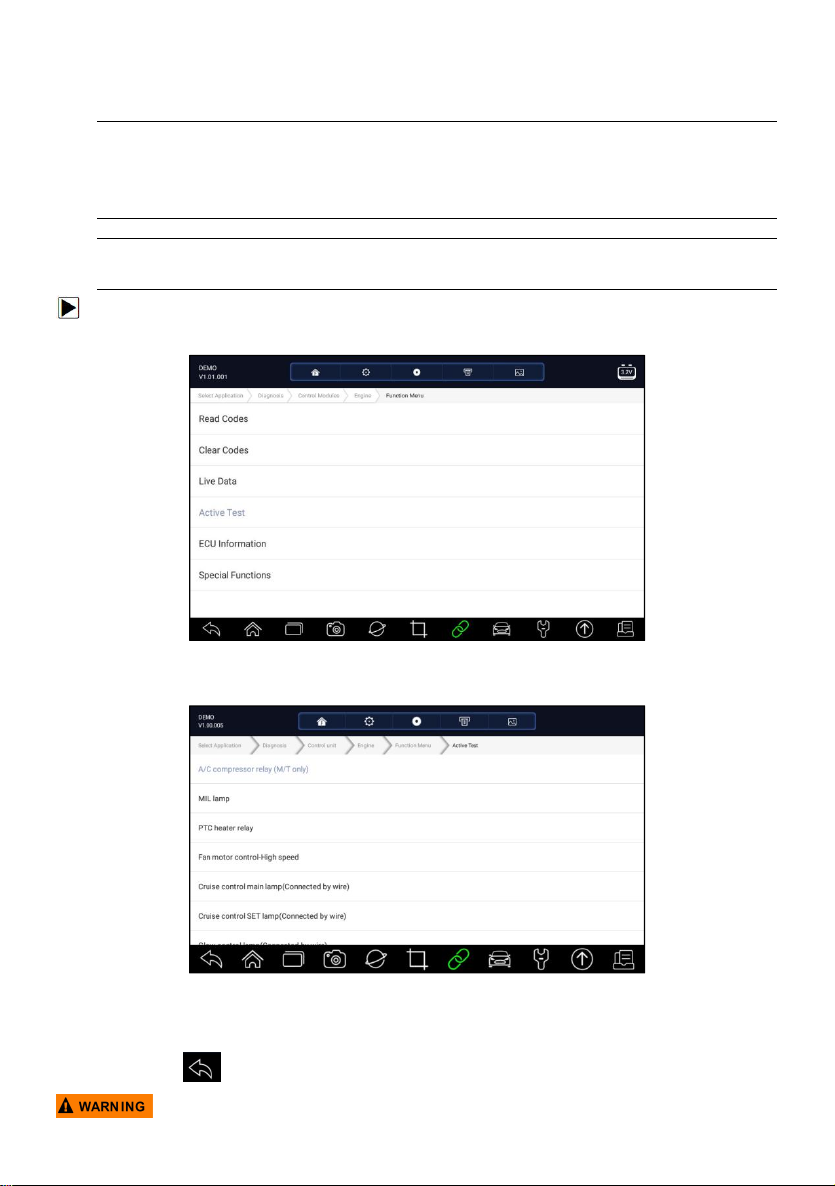
1. Press Active Test from the menu and a list of available options displays.
Figure 5-27 Sample Function Menu Screen
2. Select an option to start the test and live data of the selected test displays.
Figure 5-28 Sample Active Test Screen
3. Follow on-screen instructions to make proper selections and operations to
complete the tests.
4. Press to exit.
Premier Diagnostic Platform i70Pro User's Manual V1.01
48
Page 49
● Before running any tests, always observe the safety instructions provided in
this manual and the warnings provided by the vehicle manufacturer. In
addition, follow any warnings and descriptions provided on the scanner
screens.
● Never run the tests while the vehicle is moving.
5.2.6 Special Functions
These functions perform various component adaptations of the control
module under test, allowing you to recalibrate or configure certain
components after making repairs or replacement.
5.3 Special Functions
These functions perform various component adaptations, allowing you to
recalibrate or configure certain components after making repairs or
replacement. Typical service operation screens are a series of menu driven
executive commands. Follow on-screen instructions to complete the
operation.
Generally the menu options are:
●
Service
●
Programming
● Hot Function
5.3.1 Service
The Service section is specially designed to provide you quick access to the
vehicle systems for various scheduled service and maintenance
performances.
To start a service function:
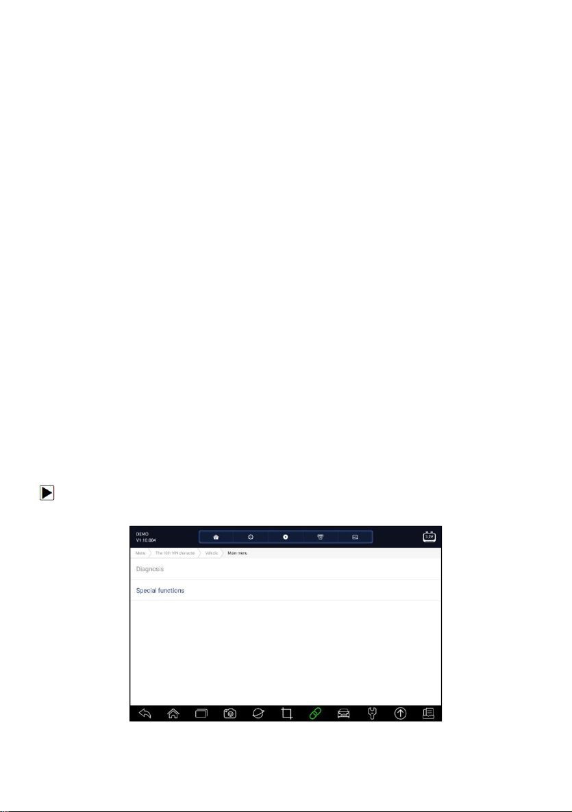
1. Select Special Functions from main menu and press ENTER to confirm.
Figure 5-29 Sample Main Menu Screen
Premier Diagnostic Platform i70Pro User's Manual V1.01
49
Page 50
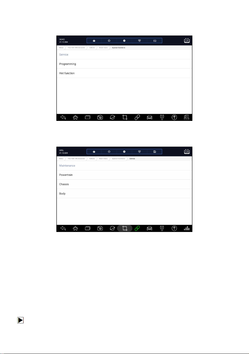
2. Select Service option from the Special Functions menu. A list of available
services display.
Figure 5-30 Sample Special Functions Screen
3. Select the service you want to perform. Follow on-screen instructions to
make proper selections and operations to complete the tests.
Figure 5-31 Sample Service Function Screen
5.3.2 Coding and Programming
i70Pro allows for the coding and programming of a replacement control
module or changing previously stored incorrect coding.
Coding also is known as Teach-in Program or Component Adaptation. It is
the process of selecting and activating one program for a specific vehicle
from a set of programs that the factory installed in the control module. This
allows one control module to be used for different models, countries, and
emission applications.
Programming is the process of taking a blank control module and then adding
the correct vehicle program to memory.
To start a coding & programming test:
1. Select Special Functions from main menu and press ENTER to confirm.
Premier Diagnostic Platform i70Pro User's Manual V1.01
50
Page 51
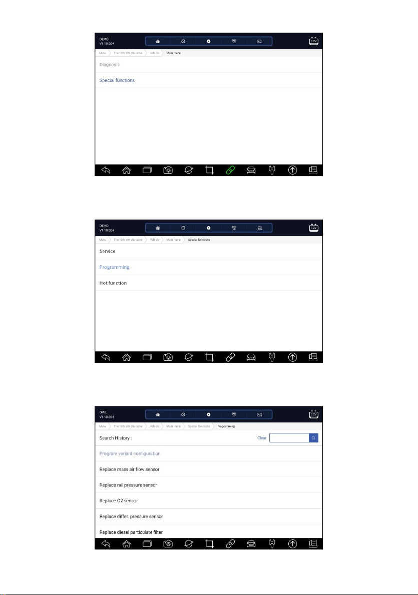
Figure 5-32 Sample Main Menu Screen
2. Select Programming option from the Special Functions menu. A list of
available services display.
Figure 5-33 Sample Special Functions Screen
3. Select the function you want to test. Follow on-screen instructions to make
proper selections and operations to complete the tests
Premier Diagnostic Platform i70Pro User's Manual V1.01
51
Page 52
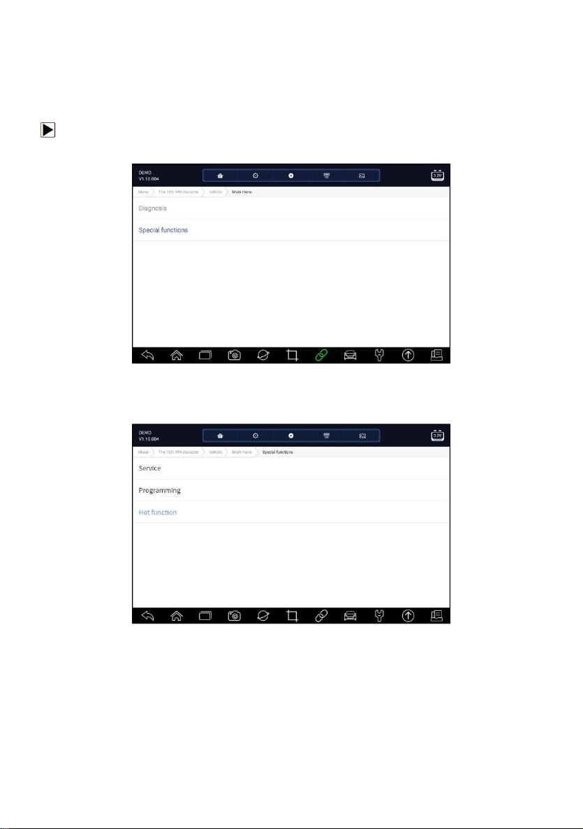
Figure 5-34 Sample Programming Screen
5.3.3 Hot Functions
It is designed for most common used functions like battery configuration, oil
light reset and provides quick access to service functions for the technicians.
To start a test:
1. Select Special Functions from main menu and press ENTER to confirm.
Figure 5-35 Sample Main Menu Screen
2. Select Hot Functions option from the Special Functions menu. A list of
available services display.
Figure 5-36 Sample Special Functions Screen
3. Select the function you want to test. Follow on-screen instructions to make
proper selections and operations to complete the tests
Premier Diagnostic Platform i70Pro User's Manual V1.01
52
Page 53

Figure 5-37 Sample Hot Functions Screen
6 Maintenance
This section gives brief instructions of the most commonly required service
and maintenance operations. Typical service operation screens are a series
of menu driven executive commands. Follow on-screen instructions to
complete the operation.
Available service and maintenance options include:
● Oil Light Reset
● EPB Service
●
Battery Configuration
●
DPF Regeneration
●
TPS/TBA
● SAS Calibration
● CVT
● Gear Learn
●
TPMS Programming Service
●
Odometer
●
Injector coding
● ABS Bleeding
● Key Programming/Immobilizer
6.1 Oil Light Reset
Oil Light Reset menu allows you to reset the service lamps on the
instrument cluster. The Service Indicator System is designed to alert the
driver when the vehicle is due for a service.
Oil service reset methods are determined by the vehicle being tested.
Depending on the vehicle being tested, any of the following means displays:
Premier Diagnostic Platform i70Pro User's Manual V1.01
53
Page 54

● Oil Reset with One Button - applicable to GM models only. It offers quick
and simple oil service reset with the click of one button.
●
Manual Reset - almost all Asian vehicles and most American and
European vehicles have mechanical oil service indicator reset. The
service tool does not have to communicate with the vehicle being tested,
but guides you to complete the service manually by providing
step-by-step on-screen instructions.
When Manual Reset is selected and the vehicle being tested identified, a
procedure opens on the screen. Scroll with arrow keys to read the entire
procedure and performing the necessary steps as directed by the
on-screen instructions. The exact order of the test operation steps may
vary depending on the test vehicle. Be sure to follow all on-screen
instructions. The manual reset procedure can be interrupted and aborted
if the ignition key position is changed.
●
Auto Reset - Auto Reset is a bi-directional communication procedure
directed by the service tool. The service tool displays guides for you
through the process. A number of instructions that require a response to
continue display, including an option to clear any stored codes once the
interval has been reset. Follow the on-screen instructions.
6.2 Electronic Parking Brake (EPB) Service
EPB Service menu allows you to perform the service and maintenance of
brake systems, including deactivation and activation of the brake control
system, bleeding brake fluid, opening and closing brake pads, and setting
brakes after disc or pad replacement, on multiple brands of vehicles where
electronic brake systems are fitted.
Some tests display a command to the operator. For example, if “Pressing
Brake Pedal” displays, the operator has to press and hold the brake pedal
and then continue. Actual tests vary by vehicle manufacturer, year, make.
Typical special test options include:
● Deactivate/Activate SBC/EPB systems - allows to deactivate brakes for
further service or maintenance work on brake systems or activate brakes
when service or maintenance work on brake systems are completed.
●
Adaptation on Audi A8 - allows to set new pad thickness of rear brakes
calipers after changing brake discs & pads on Audi A8 models.
●
Replace hydraulic brake systems fluid/bleed brake system on
Mercedes SBC vehicles - allows to change brake fluid/bleed brake
system.
● Perform service reset and service position on BMW EPB vehicles -
allows to do the CBS reset and CBS correction for front brake and rear
brake.
Premier Diagnostic Platform i70Pro User's Manual V1.01
54
Page 55

● Perform activation/service work on Volvo PBM vehicles – allows to
perform installation check, applying parking brake, releasing parking
brake, activating service mode and exiting service mode.
●
Reset memory on Toyota EPB vehicles – allows to clear the learned
memory of the EPB ECU.
● Perform brake cable replacement and electric parking brake
replacement – allows to fit in or remove the brake cable safely, adjust
brake cable’s tension and calibrate the electric parking brake
replacement.
●
Save and write clutch pedal programming on Renault EPB vehicles –
allows to save clutch pedal programming on Renault vehicles fitted with
manual gearbox. After this command is activated, the tool allows to "flash"
the electric parking brake unit with the saved clutch data.
●
Perform control function and reset function on Opel EPB vehicles allows to apply/release park brake cable service, provides park brake
cable service replacement procedures and calibrate the parking brake
systems after brake service.
● Sensor calibration on Honda EPB vehicles - allows to program the
current output value of each sensor into the electric parking brake unit.
●
Provides parking brake unjam procedure and perform longitudinal
accelerometer calibration on Land Rover EPB vehicles - allows to
drive the electronic park brake so it is unjamed in the releasing direction
and then drive it into mounting position or the latching position; also
allows to perform longitudinal accelerometer calibration.
●
EPB systems must be deactivated before carrying out any
maintenance/service work on the brakes such as changing of pads, discs
and calipers.
● Use proper tools to avoid the risk of body injuries of mechanics and
technicians and damage to the brake system.
●
Make sure the vehicle is properly blocked after deactivation of the
systems.
6.3 Battery Replacement (BRT)
BRT menu lets you to validate new battery, clear faults from the dashboard
and display current battery details of the vehicle such as Audi, BMW, Citroen,
Peugeot, Seat, Skoda, Volvo, VW and Ford.
1. Replace the old battery with the new one. Ensure the key is not in the
ignition.
2. Connect the scanner to the vehicle’s 16 pin Data Link Connector (DLC)
with the diagnostic cable.
Premier Diagnostic Platform i70Pro User's Manual V1.01
55
Page 56

3. Boost the device and select BRT; it will display all the vehicle makes
available. Choose your vehicle make and follow the scanner instruction to
start.
●
Sensor calibration on Honda EPB vehicles - allows to program the
current output value of each sensor into the electric parking brake unit.
● Perform BRT on Citroen/Peugeot cars – make several selections to
confirm your car model, and then complete the battery replacement
following on-screen instructions.
●
Perform BRT on Audi/VW/Seat/Skoda cars - after communicating with
vehicles, there’s two options under Replace battery menu - Validate
battery and Display data.
- Validate battery menu lets you to recode the new battery to the
vehicle’s ECU and to turn off dashboard warning lights. The on-screen
instructions would guide you step by step to complete the replacement.
- Display Data menu lets you to check the battery information or battery
replacement records
● Perform BRT on BMW/Volvo cars - after making several selections to
confirm your vehicle model, you can select Display data, Validate
Battery or Clear codes from Function menu.
6.4 Diesel Particulate Filter (DPF) Regeneration
DPF Regeneration menu let you perform the DPF cleaning to clear the
blockage through continuous burning of the particulates captured in the DPF
filter. When a DPF regeneration cycle is completed, the DPF light
automatically goes off.
6.5 Throttle Body Alignment (TPS/TBA)
It’s very common to see a customer pull into the shop with a Volkswagen or
Audi that just will not idle correctly. One of the possible causes is that the
throttle position is not known. When the motion range is not known, the ECU
simply has no idea where to set the throttle. The ECU must know the full
range of motion of the throttle in order for it to properly control the engine.
Using the throttle position sensors in the throttle body, the ECU learns the full
open and full closed positions through various states (idle, part throttle, WOT)
known as a Throttle Body Alignment (TBA).
6.6 Steering Angle Sensor (SAS) Calibration
SAS Calibration menu let you perform calibration of the Steering Angle
Sensor, which permanently stores the current steering wheel position as
straight-ahead in the sensor EEPROM. On successful calibration of the
sensor, its fault memory is automatically cleared.
Premier Diagnostic Platform i70Pro User's Manual V1.01
56
Page 57

6.7 Continuous Variable Transmission (CVT)
This function is used to reset the compensation code and initialize the ECT
after a solenoid valve or valve body assembly has been replaced.
6.8 Gear Learning
The crankshaft position sensor learns crankshaft tooth machining tolerance
and saves to the computer to more accurately diagnose engine misfires. If
tooth learning is not performed for a car equipped with Delphi engine, the MIL
turns on after the engine is started. The diagnostic device detects the DTC P
1336 'tooth not learned'. In this case, you must the diagnostic device to
perform tooth learning for the car. After tooth learning is successful, the MIL
turns off.
After the engine ECU, crankshaft position sensor, or crankshaft flywheel is
replaced, or the DTC 'tooth not learned' is present, tooth learning must be
performed.
6.9 Tire Pressure Monitoring System Programming
TPMS Service menu allows you to check the tire sensor IDs from the vehicle
ECU and to perform TPMS programming and reset after tires and/or TPM
sensors are replaced and/or tires are rotated.
6.10 Odometer
This function allows you to revise the date of odometer and write the original
date into new odometer.
6.11 Injector Coding
Write injector actual code or rewrite code in the ECU to the injector code of
the corresponding cylinder so as to more accurately control or correct
cylinder injection quantity. After the ECU or injector is replaced, injector code
of each cylinder must be confirmed or re-coded so that the cylinder can better
identify injectors to accurately control fuel injection.
6.12 ABS Bleeding
Anytime the brake system is opened to replace components such as calipers,
wheel cylinders, the master cylinder, or brake lines or hoses, air gets inside.
The air has to be removed by bleeding the brakes if you want a firm brake
Premier Diagnostic Platform i70Pro User's Manual V1.01
57
Page 58
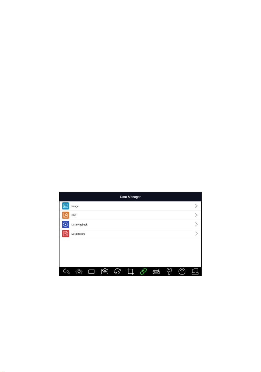
pedal. Air trapped in the lines, calipers or wheel cylinders will make the pedal
feel soft and spongy. Air is compressible, so when the brakes are applied any
air bubbles in the system must first be compressed before the hydraulic fluid
will transmit pressure to apply the brakes.
6.13 Key Programming/Immobilizer
The transponder key is an aftermarket option that can be programmed for a
number of vehicles. Also known as a chip key or ignition key, this key offers a
level of convenience and security for your car. If your car is equipped with a
chip key system, only a programmed key can turn on the ignition in your
vehicle.
7 Data Manager
Data Manager menu let you review stored screenshots and test reports,
playback recorded live data and other saved files.
Typical menu options include:
● Image
● PDF
● Data Playback
●
Data Record
Figure 7-1 Sample Data Manager Screen
7.1 Image
Image option leads to screens for review of stored screenshots. In case a
failure of i70Pro application or the Android system occurs, please just take a
screenshot and send it to our team to help with the troubleshooting.
Premier Diagnostic Platform i70Pro User's Manual V1.01
58
Page 59
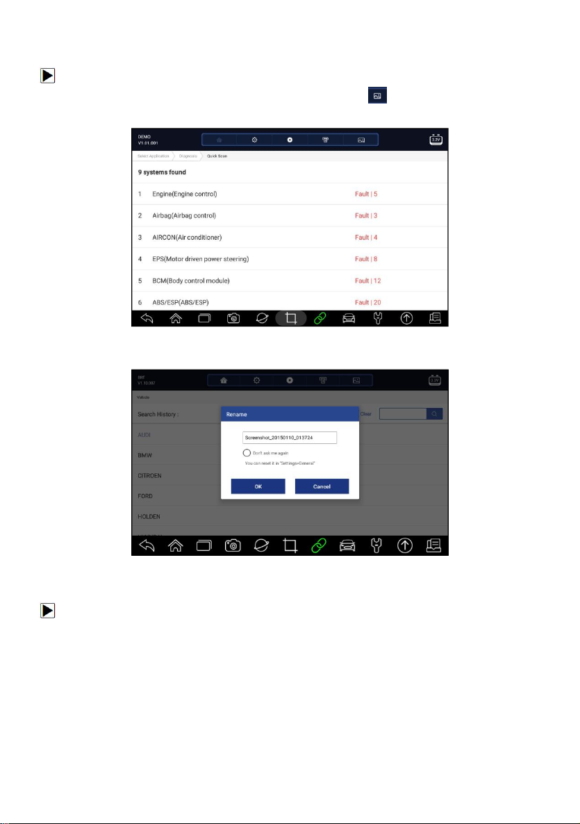
7.1.1 How to Save an Image
To take a screenshot:
1. If want to save data of current screen, press at the title bar to take a
screenshot.
Figure 7-2 Sample Screenshot Screen
2. Add a description of the image, and press the OK to save.
Figure 7-3 Sample Screenshot Screen
7.1.2 Review Image
To review the screenshots:
1. Press Data Manager from home screen of i70Pro diagnostic application.
2. Press Image and all available pictures will be displayed.
Premier Diagnostic Platform i70Pro User's Manual V1.01
59
Page 60
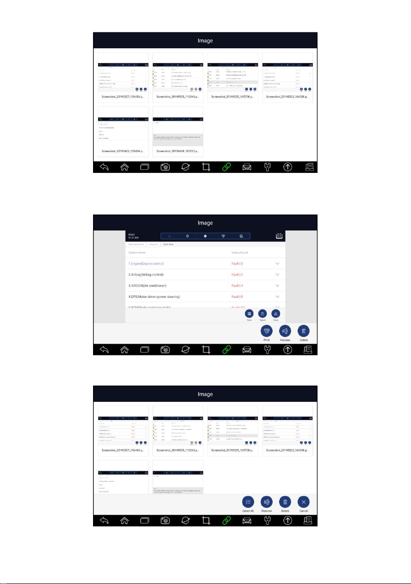
Figure 7-4 Sample Browse Picture Screen
3. To delete a picture, tap button Delete and answer OK to delete. Press
Print to print the pictures and press Rename to change the picture name.
Figure 7-5 Sample Edit Picture Screen
4. Long press the screen to edit all pictures like Rename or Delete.
Figure 7-6 Sample All Pictures Edit Screen
Premier Diagnostic Platform i70Pro User's Manual V1.01
60
Page 61
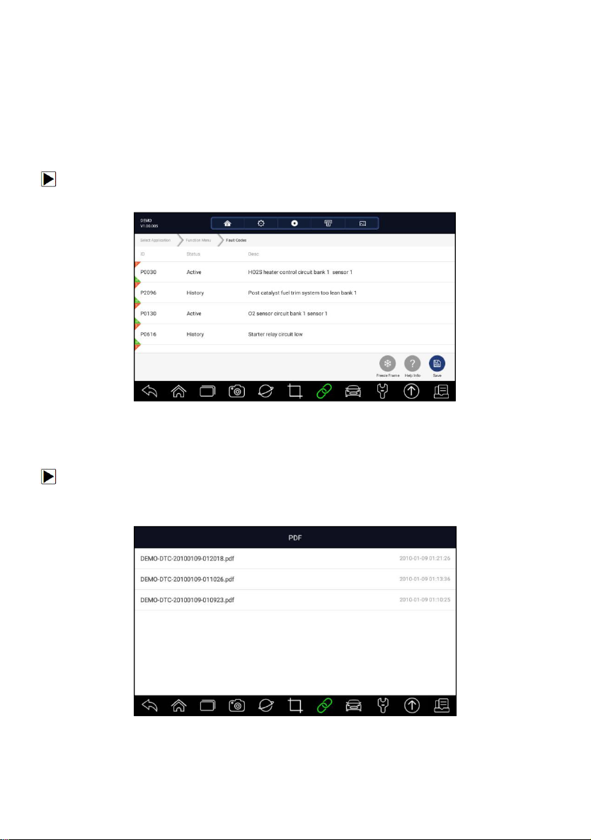
7.2 PDF Report
PDF option leads to screens for review of the vehicle test reports. You just
need to press the PDF icon on the test screen, add a description and press
OK button to save.
7.2.1 How to Create a PDF Report
To create a PDF report:
1. If need be, press the Save icon on the test screen to save the data.
Figure 7-7 Sample of DPF Screen
2. Add a description to the DPF report, and press the OK to save.
7.2.2 Review PDF Report
To review the PDF reports:
1. Press Data Manager from home screen of i70Pro diagnostic application.
2. Press PDF and all available PDF files will be displayed.
Figure 7-8 Sample Browse PDF Screen
3. Long press the screen to edit all PDF files like Rename or Delete the files.
Premier Diagnostic Platform i70Pro User's Manual V1.01
61
Page 62
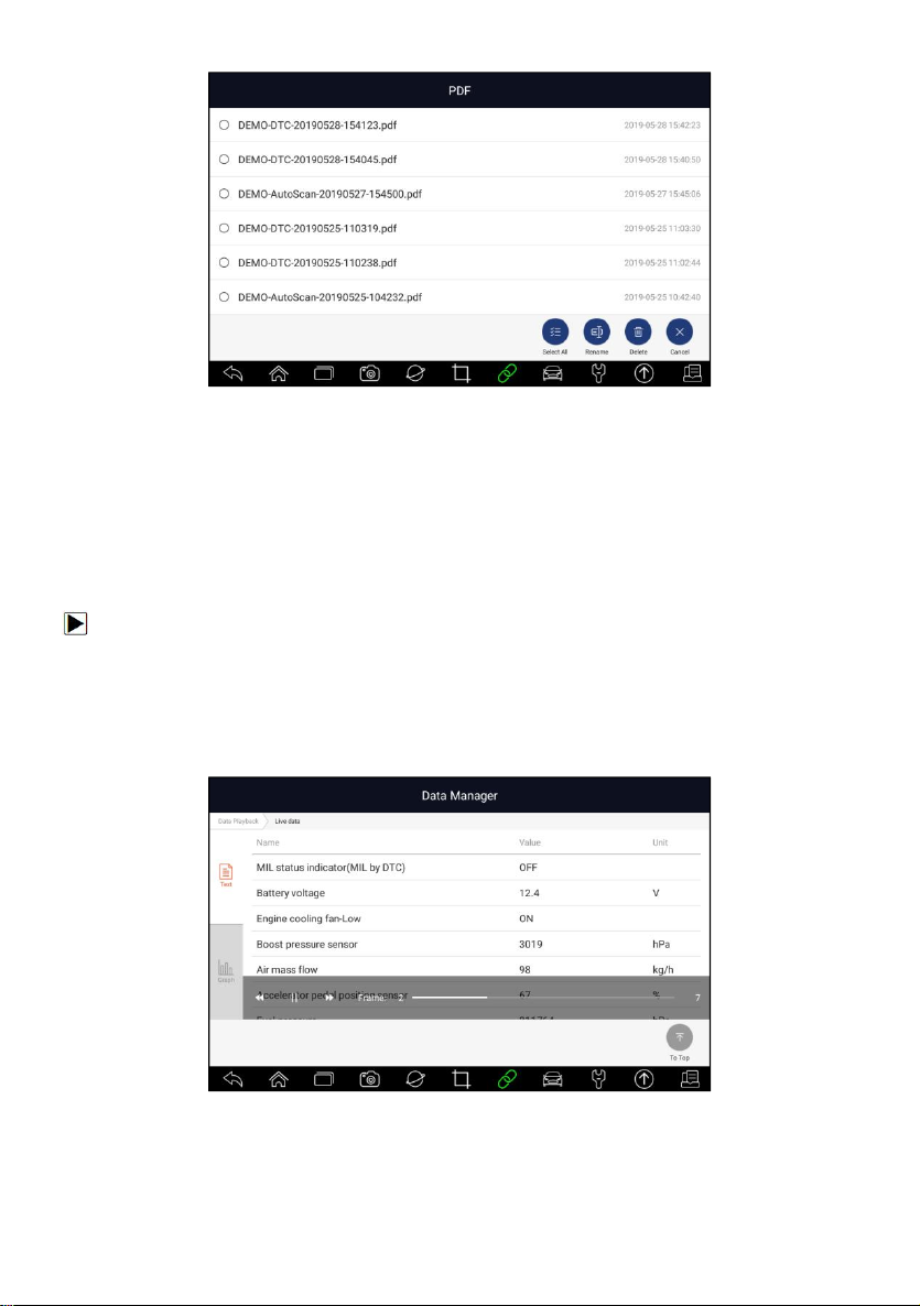
Figure 7-9 Sample Edit PDF Screen
7.3 Data Playback
The Data Playback option leads to screens for review of recorded live data.
Playing back a recording is just like using the scan tool on a live vehicle. It let
you review live data in text, graph and graph merging formats. Playback
speed and direction (forward or reverse) can also be controlled.
To review recorded live data:
1. Press Data Manager from home screen of i70Pro diagnostic application.
2. Press Data Playback and all available records display.
3. Select one record and press Select All button or choose some parameters,
then press the OK button to review. All recorded parameters display in text
format by default.
Figure 7-10 Sample Data Playback Screen
4. To view parameter graphs, press the Graph tab. And to merge the graphs,
press the tab Merge Graph or press the tab Multi Graph to view multiple
plots.
Premier Diagnostic Platform i70Pro User's Manual V1.01
62
Page 63
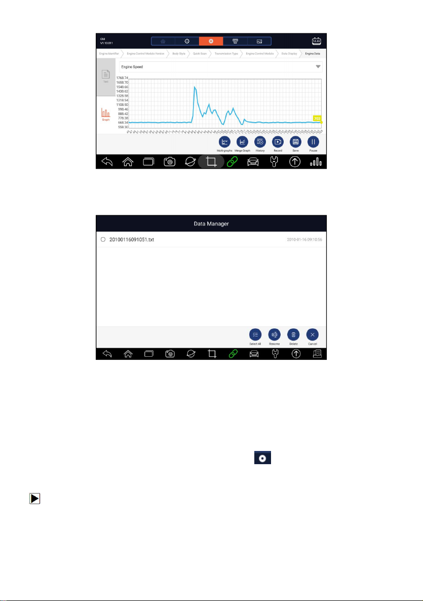
Figure 7-11 Sample Graph Screen
5. To move forward or reverse back of the playing, just drag the progress bar
forward or reverse. To stop, press the Pause button.
Figure 7-12 Sample Edit Data Playback Screen
6. Long press the record to Rename or Delete the records.
7.4 Data Logging & Data Record
Data Logging collects the communication data between the scanner and the
vehicle under test to help with troubleshooting of diagnostic failures. The logs
will be saved to the tablet. The logging icon displays on the title bar of
the diagnostic screen whenever the scanner builds communication with the
vehicle.
To create a debug data log:
1. When connected to a car, click the Data Logging icon to start record the
communication data between the tablet and the vehicle.
Premier Diagnostic Platform i70Pro User's Manual V1.01
63
Page 64
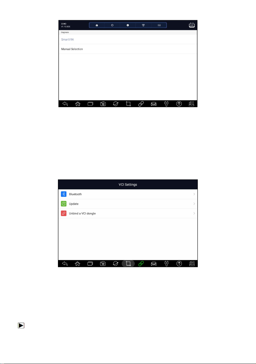
Figure 7-13 Sample Data Logging Screen
2. Click the Data Logging icon again to stop the recording and data log
record will be saved automatically.
3. Go to Data Manager -- Data Record to view the stored logs.
8 VCI Manager
VCI Manager allows you to make Bluetooth pairing between the tablet and
the VCI dongle, update VCI firmware and unbind a VCI dongle.
Figure 8-1 Sample VCI Manager Screen
8.1 Bluetooth
During the Bluetooth pairing process, make sure the VCI dongle is correctly
powered by either connected to a vehicle or connect to the tablet with the
USB Type-B cable.
To make Bluetooth pairing of the VCI dongle and the tablet
Premier Diagnostic Platform i70Pro User's Manual V1.01
64
Page 65
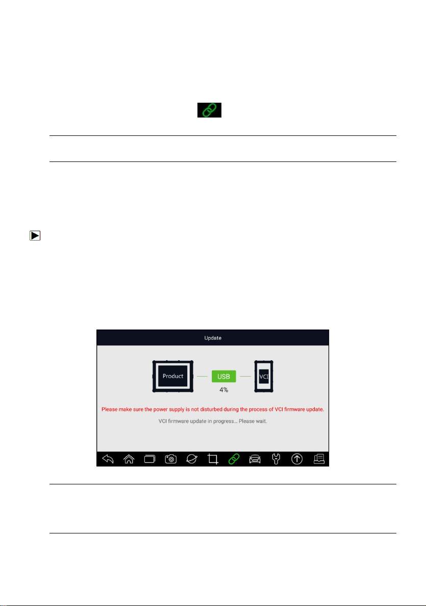
1. Connect the VCI dongle with a vehicle via diagnostic cable or connect to
the tablet with the USB Type-B cable.
2. Click the VCI Manager application on the i70Pro Menu.
3. Select Bluetooth option from the list.
4. Select the right device with the i70Pro serial number from the list.
5. When paring is successfully done, the status is shown as Paired.
6. Wait a few seconds, and the button at the toolbar illuminates green,
indicating the tablet is connected to the VCI dongle via Bluetooth.
NOTE
A VCI dongle can be paired with ONE tablet each time.
8.2 Update Firmware
Update option allows you to update VCI firmware when the new version is
available.
To update the VCI dongle firmware:
1. Connect the VCI dongle to the i70Pro tablet via USB or Bluetooth. And
make sure the power supply will not be disturbed during the process of
update.
2. Click the VCI Manager application on the i70Pro menu.
3. Select Update option from the option list.
4. It will start the update automatically. If update failed, please follow the
on-screen instructions to troubleshoot and repeat the process.
Figure 8-2 Sample VCI Updating Screen
NOTE
If there is a firmware update available, the update file will be saved
automatically when you try to update the diagnostic software of a vehicle.
And you will be prompted to upgrade the firmware.
Premier Diagnostic Platform i70Pro User's Manual V1.01
65
Page 66
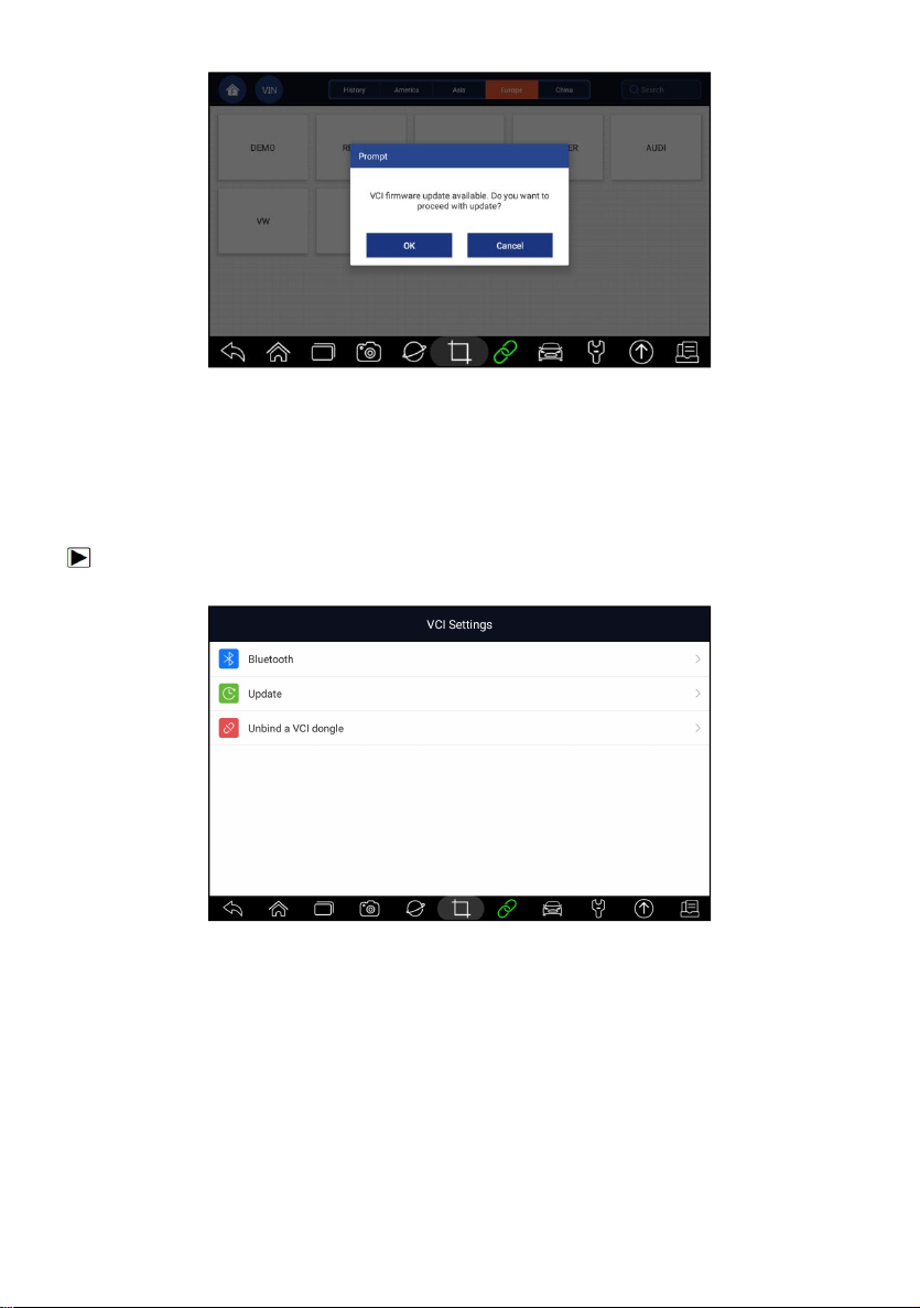
Figure 8-3 Sample Update Prompt Screen
8.3 Unbind a VCI dongle
This option allows you to unbind a VCI dongle when the VCI dongle is
defective or stolen.
To unbind a VCI dongle:
1. Click the VCI Manager application on the i70Pro Menu.
Figure 8-4 Sample VCI Manager Screen
2. Select Unbind a VCI dongle option from the option list and press OK to
confirm.
Premier Diagnostic Platform i70Pro User's Manual V1.01
66
Page 67
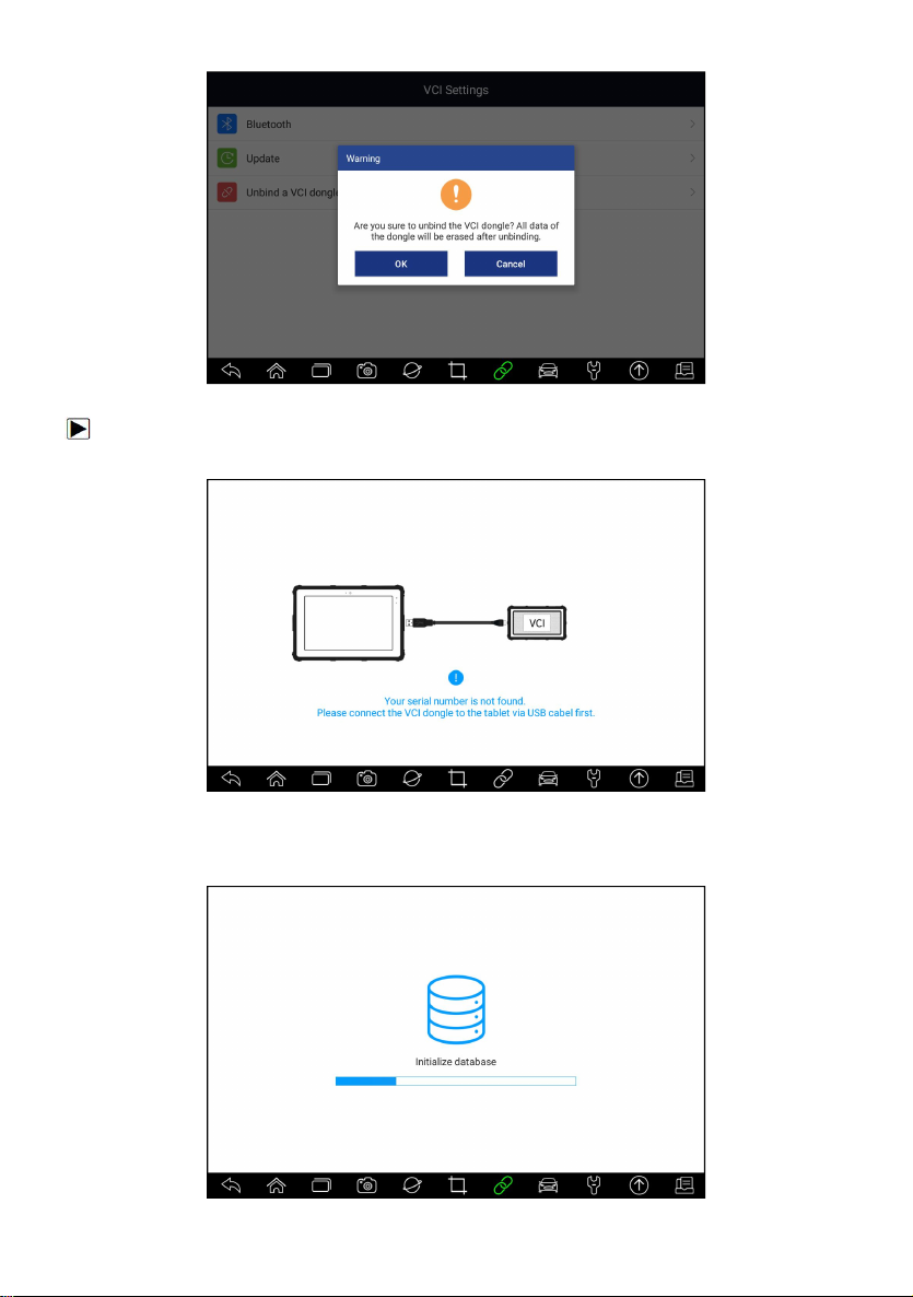
Figure 8-5 Sample Unbind Prompt Screen
To bind a new VCI dongle:
1. Connect the VCI dongle with i70Pro tablet via USB cable.
Figure 8-6 Sample Bind Prompt Screen
2. When system database initialization finished, you can use the tablet
normally.
Premier Diagnostic Platform i70Pro User's Manual V1.01
67
Page 68
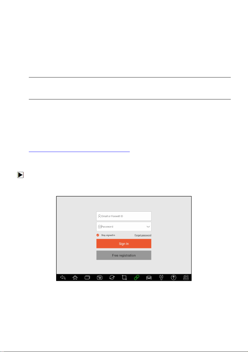
Figure 8-7 Sample Data Initialization Screen
9 Registration and Update
The scanner can be updated to keep you stay current with the latest
development of diagnosis. This section illustrates how to register and update
your scan tool. You can register both on Foxwell website or by the built-in
update client.
NOTE
Before registration and updating, please make sure your network works
correctly and the tablet is fully charged or connect to external power supply.
9.1 Registration
If you are new to FOXWELL, please get a FOXWELL ID first either by
●
Registering with the built-in update client;
●
Or registering through our website with the URL:
http://www.foxwelltech.us/register.html
9.1.1 Register with Built-in Update Client
You are allowed to create a Foxwell ID with the built-in update client.
To register with built-in update client:
1. Press Update from home screen of i70Pro diagnostic application, and the
update client starts up automatically.
Figure 9-1 Sample Update Client Main Screen
2. Click Free Registration button, and the registration window will pop up.
Premier Diagnostic Platform i70Pro User's Manual V1.01
68
Page 69
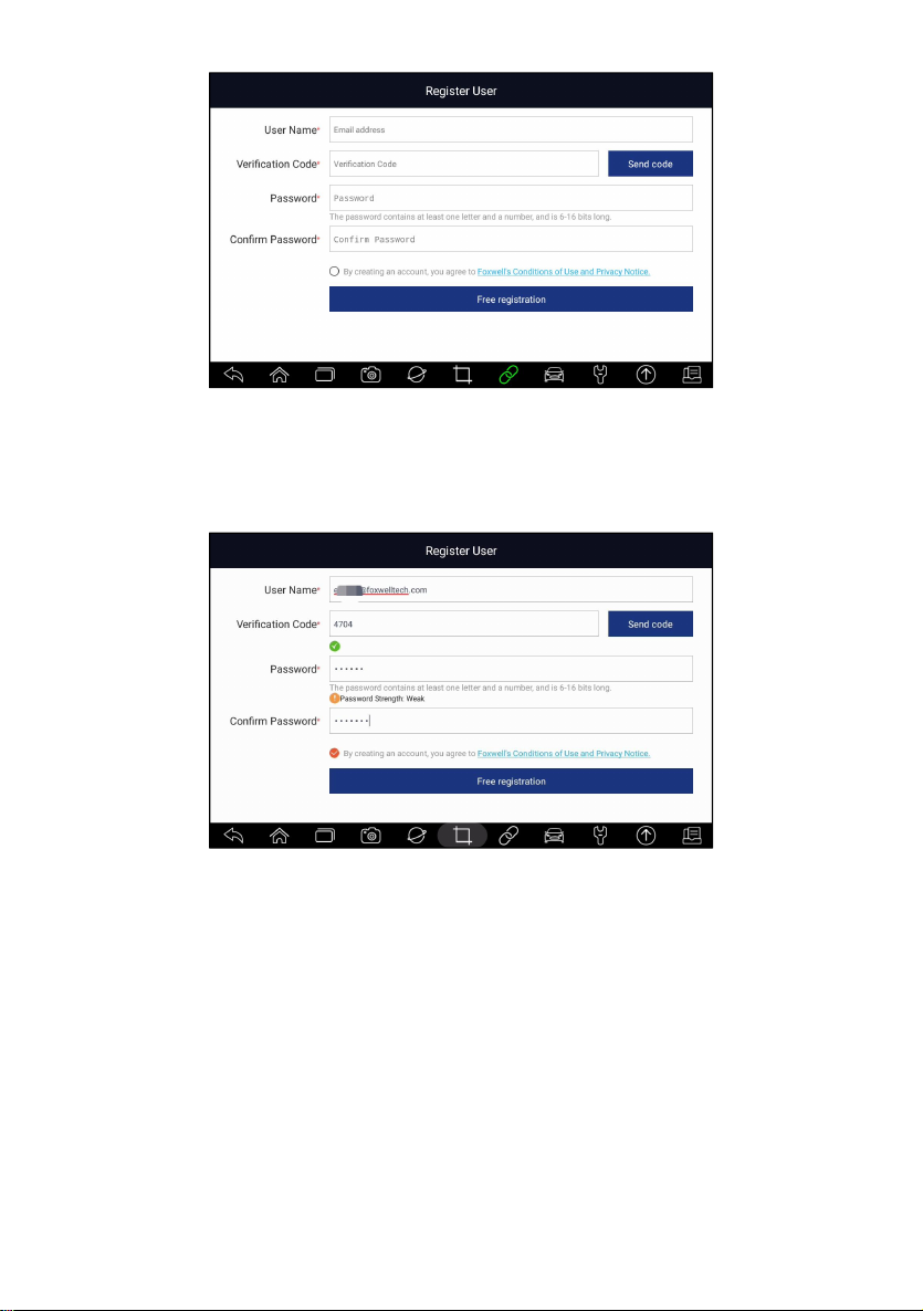
Figure 9-2 Sample ID Registration Screen
3. Enter one of your email addresses as your user ID and click the Send
Code button. We will send a 4-digit verification code to the email you just
entered. Find the security code in your mailbox, input the code, create a
password and click Free Registration to complete.
Figure 9-3 Sample ID Registration Screen
4. “The account has been created successfully” message will appear if you
registered successfully.
Premier Diagnostic Platform i70Pro User's Manual V1.01
69
Page 70
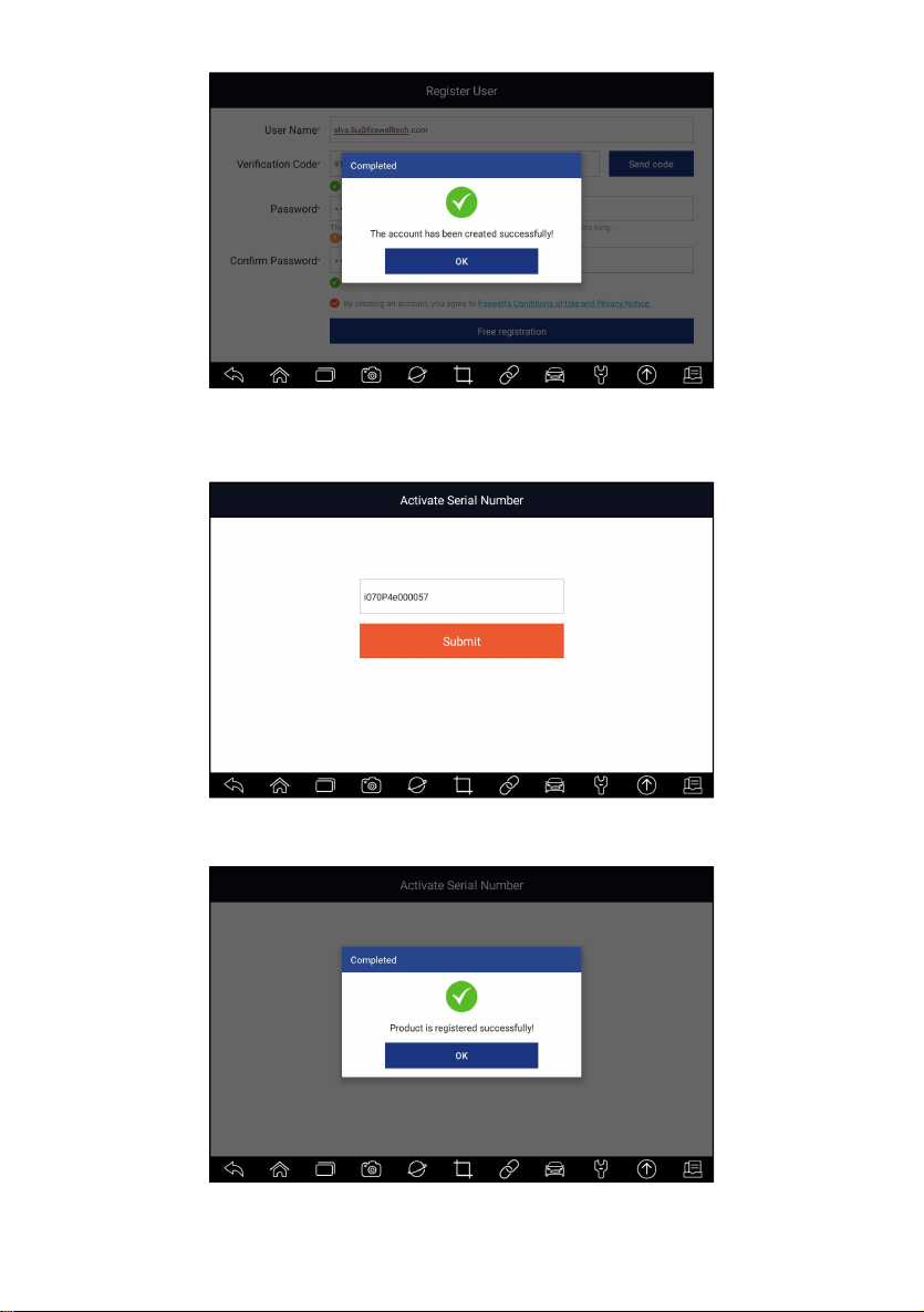
Figure 9-4 Sample Registration Done Screen
5. The serial number will be recognized automatically and click Submit to
activate the scanner.
Figure 9-5 Sample Product Activation Screen
6. The product is registered successfully.
Figure 9-6 Sample Activation Done Screen
Premier Diagnostic Platform i70Pro User's Manual V1.01
70
Page 71
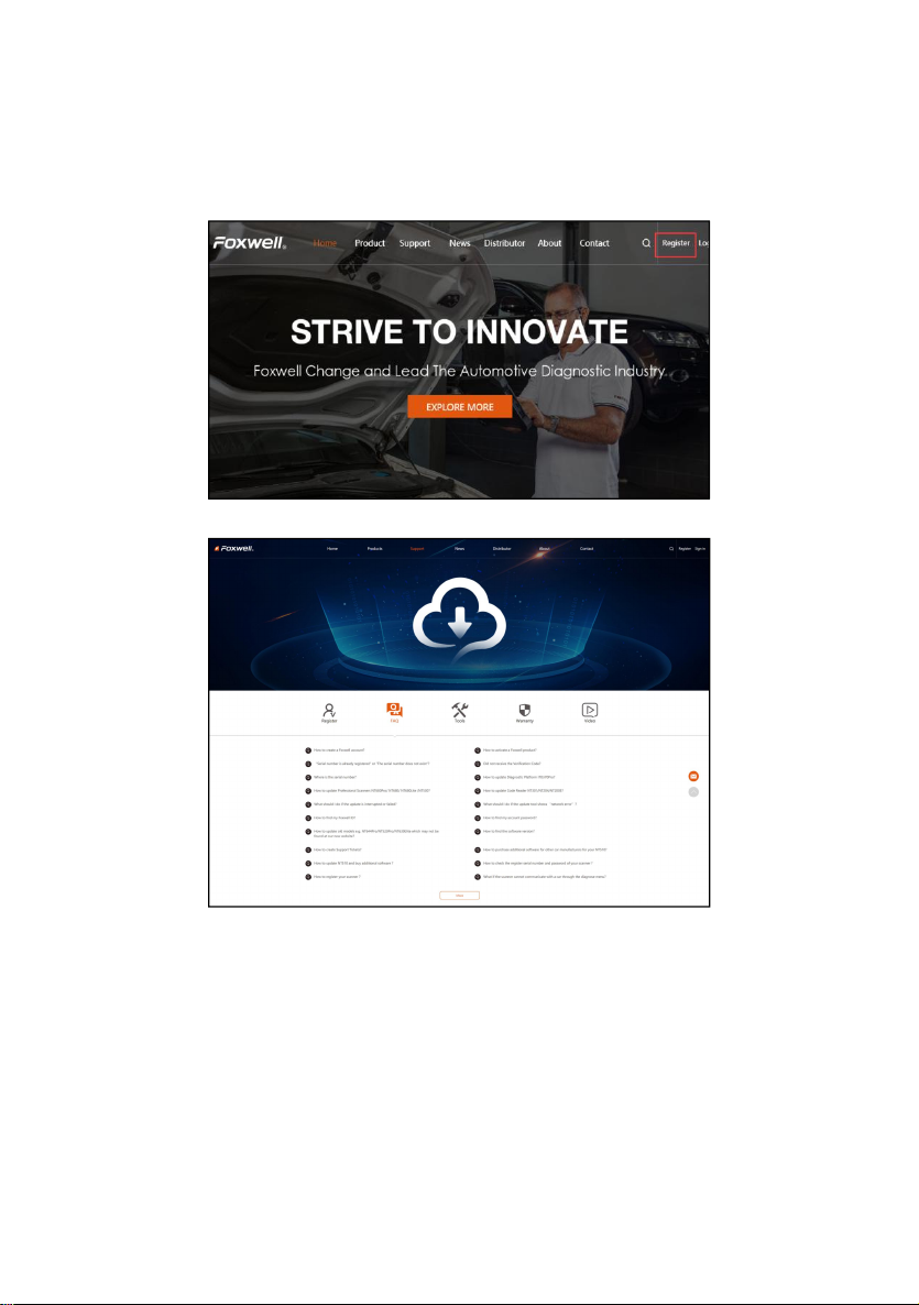
9.1.2 Register through Website
To register through our website:
1. Visit Foxwell official website www.foxwelltech.us and press Register icon,
or go to the registration page by selecting Support from home page and
then click Register.
Figure 9-7 Sample Website Register Screen
Figure 9-8 Sample Website Register Screen
2. Enter one of your email addresses as your user ID and click the Send
Code button. We will send a 4-digit verification code to the email you just
entered. Find the security code in your mailbox, input the code, create a
password and click Free Registration to complete.
Premier Diagnostic Platform i70Pro User's Manual V1.01
71
Page 72
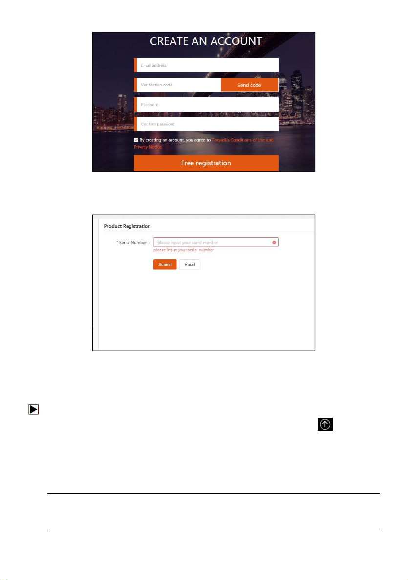
Figure 9-9 Sample Create Account Screen
3. Sign in to the Member Center, click New Registration, input the right
serial number and click Submit to activate the product.
Figure 9-10 Sample Product Register Screen
9.2 Update
To update the diagnostic application:
1. Press Update from home screen or press update shortcut at the tool
bar, and the update client starts up automatically.
2. The available updates display. Click the check box(s) in front of the
software you wish to update and then click the Update button to
download.
3. When all the items are updated, an “Update Done” message displays.
NOTE
Please make sure your network works correctly and the tablet is fully charged
or connect to external power supply.
Premier Diagnostic Platform i70Pro User's Manual V1.01
72
Page 73
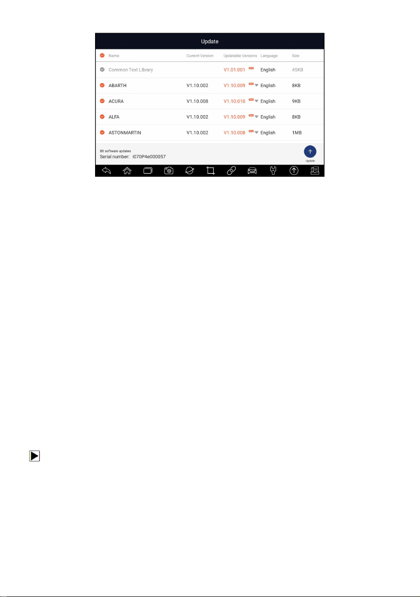
Figure 9-11 Sample Update Screen
10 Settings
This section illustrates how to program the scanner to meet your specific
needs.
When Settings application is selected, a menu with available service options
displays. Menu options typically include:
● Unit
● Language
● Push Message
●
Automatic Update
●
System Settings
●
General
● Uninstall Vehicle Software
● Print Settings
● About
10.1 Change Units
Selecting Unit opens a dialog box that allows you to choose between
Imperial customary or metric units of measure.
To change the unit setup:
1. Press Settings from home screen of the i70Pro diagnostic application.
2. Press Unit and available unit system display.
3. Select a unit system.
10.2 Language
Select Language opens a screen that allows you to choose system
language.
Premier Diagnostic Platform i70Pro User's Manual V1.01
73
Page 74
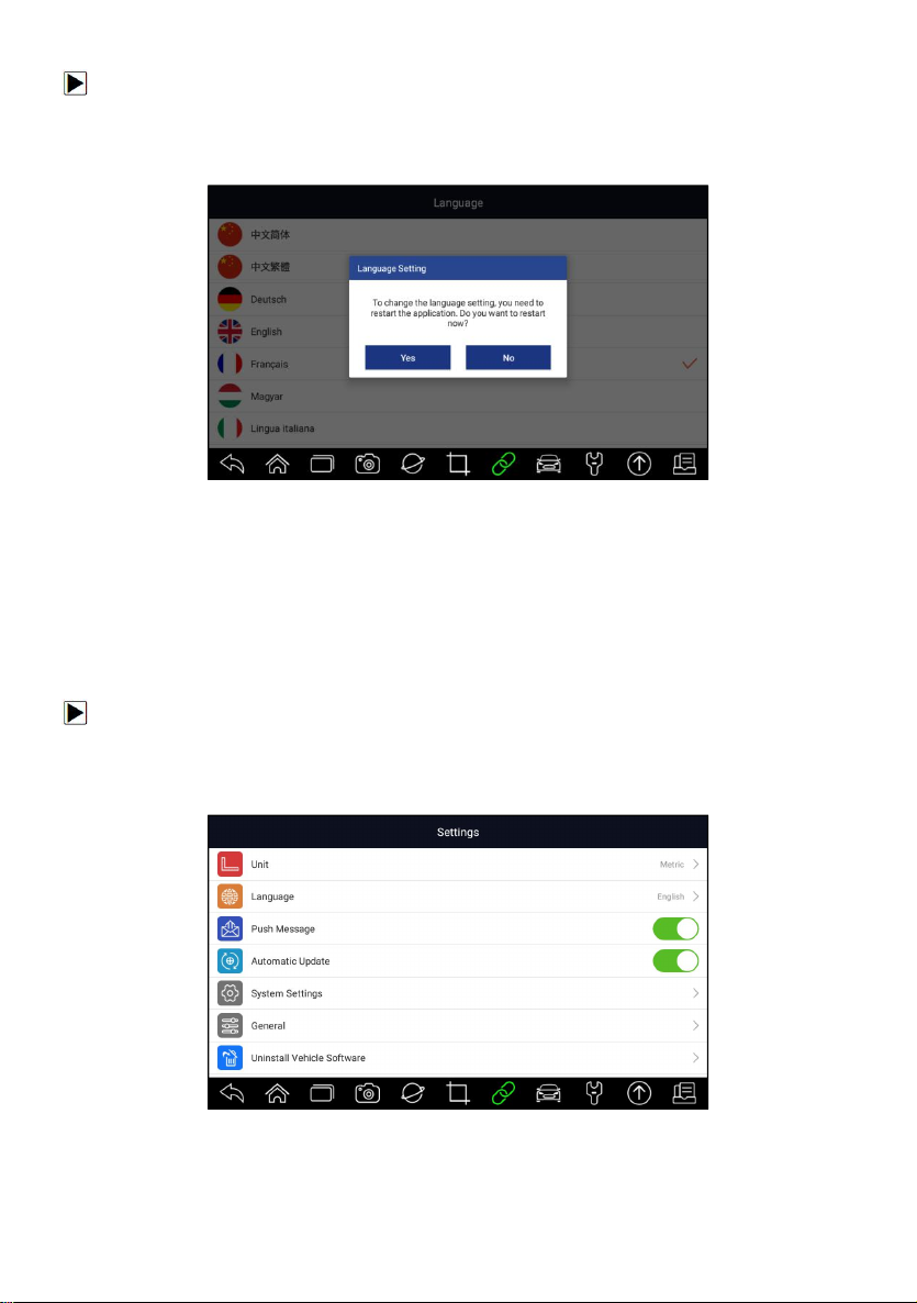
To configure system language:
1. Press Settings from home screen of the i70Pro diagnostic application and
select Language. Then all available language options display.
2. Select your preferred language and click Yes to confirm.
Figure 10-1 Sample Language Setting Screen
10.3 Push Message
This option allows you to enable/disable Push Message function. Software
updates and technical information will be delivered to you automatically. It is
highly recommended to enable it all the time, so you won’t miss out any new
updates from Foxwell.
To enable/disable Push Message:
1. Press Settings from home screen of the i70Pro diagnostic application.
2. Click the button on the right side. If turned to green, the Push Message
function is enabled. If turned to grey, the function is disabled.
Figure 10-2 Sample Push Message Setting Screen
Premier Diagnostic Platform i70Pro User's Manual V1.01
74
Page 75
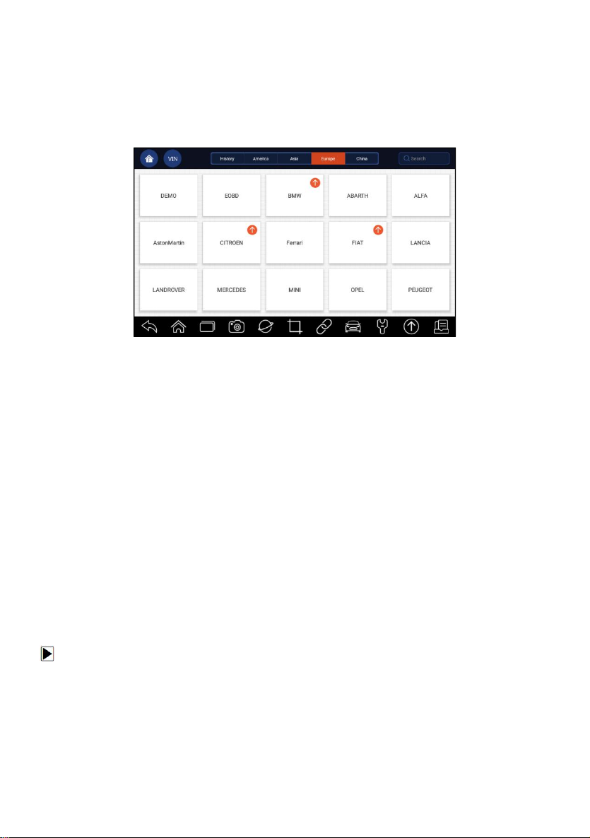
10.4 Automatic Update
This option allows you to enable/disable automatic update notice. If it is
enabled, an orange update mark will show on the upper right of the diagnostic
software icon whenever there is a new version available.
Figure 10-3 Sample Update Remark Screen
10.5 System Settings
This option provides you a direct access to the Android system settings, like
sound, display, system security and etc. Refer to Android documentation for
more information.
10.6 General
This option lets you to turn on/off the prompt when saving a file or login &
registration when started the scanner.
10.7 Uninstall Vehicle Software
This option allows you to uninstall the vehicle software installed in the
scanner.
To uninstall a vehicle software:
1. Tap Settings application on home screen of i70Pro.
2. Tap the Uninstall Vehicle Software option on the option list.
3. Choose the vehicle software you want to delete or choose Select All.
Premier Diagnostic Platform i70Pro User's Manual V1.01
75
Page 76
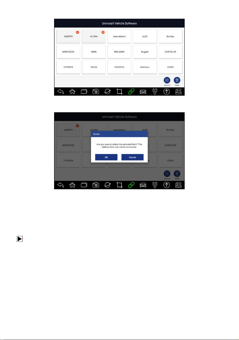
Figure 10-4 Sample Uninstall Vehicle Software Screen
4. Press Cancel to quit or and press OK to uninstall.
Figure 10-5 Sample Uninstall Vehicle Software Screen
10.8 Print Settings
This option allows you to print any data or information anywhere and anytime
either via PC network or Wi-Fi.
To setup the printer connection:
1. Tap the Settings application on home screen of i70Pro.
2. Tap the Printing Settings option on the option list.
Premier Diagnostic Platform i70Pro User's Manual V1.01
76
Page 77
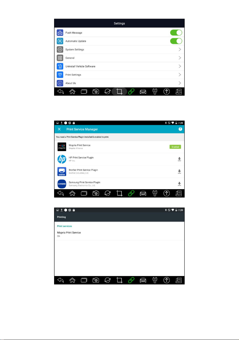
Figure 10-6 Sample Print Settings Screen
3. Tap Print Plugin Manager and turn on the Mopria Print Service, then
i70Pro will search for available printers automatically.
Figure 10-7 Sample Print Service Manager Screen
Figure 10-8 Sample Setting of Print Service Manager Screen
4. Choose the right printer.
Premier Diagnostic Platform i70Pro User's Manual V1.01
77
Page 78
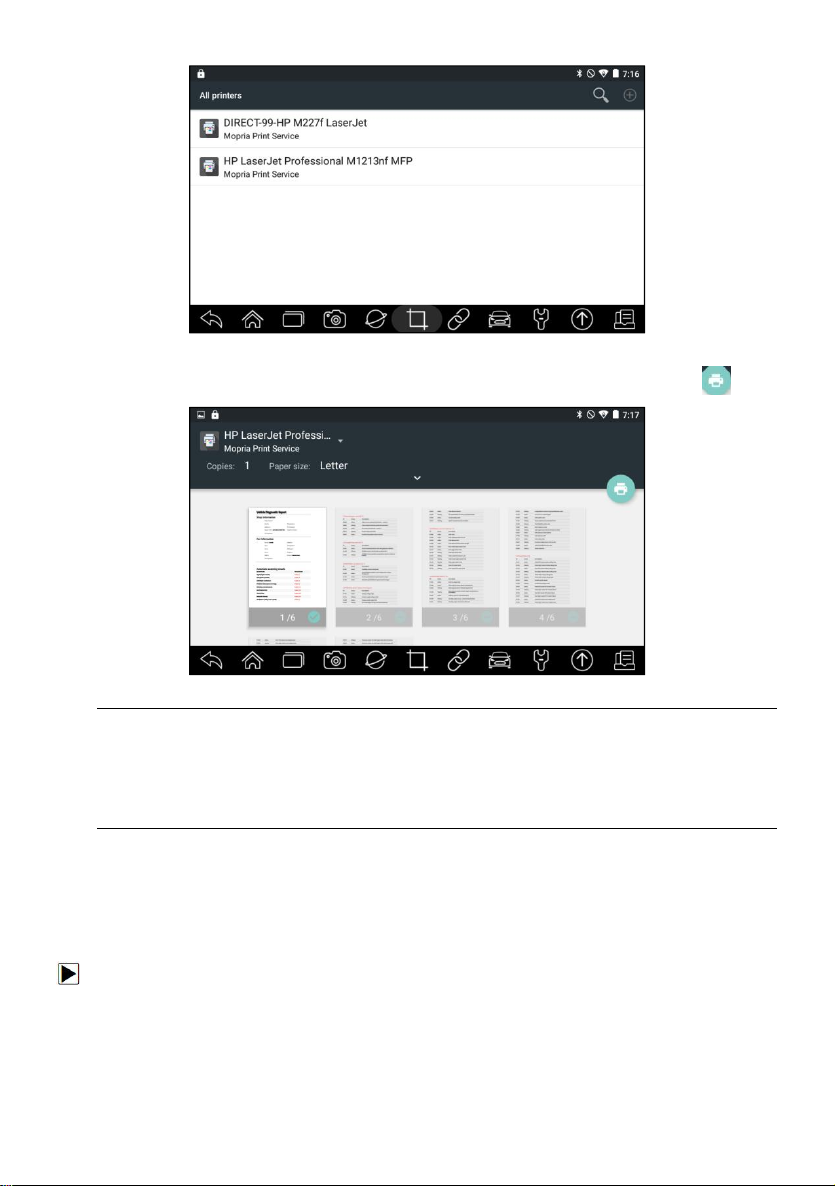
Figure 10-9 Sample of Printer Screen
5. Choose the file or report you want to print and press the print icon .
Figure 10-10 Sample of File Printing Screen
NOTE
1. Please make sure the printer and the i70Pro in the same Wi-Fi or Network
when printing.
2. If Mopria Print Service driver can’t workable for your printer, please
download the driver to work for your printer on Print Service Manager.
10.9 About
Selecting About option opens a screen that shows information about the
i70Pro, such as serial number, hardware and software version and etc.
To view information of your scan tool:
1. Press About from home screen of the i70Pro diagnostic application.
2. A screen with detailed information of the scanner displays.
Premier Diagnostic Platform i70Pro User's Manual V1.01
78
Page 79
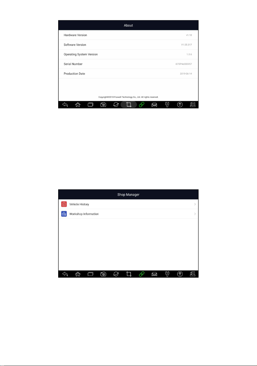
Figure 10-11 Sample Tool Information Screen
11 Shop Manager
This section illustrates how to manage the workshop information, vehicle test
records and customer information.
When Shop Manager application is selected, a menu with available service
options displays. Menu options typically include:
● Vehicle History
● Workshop Information
Figure 11-1 Sample Shop Manager Screen
11.1 Vehicle History
This function keeps records of tested vehicles, including vehicle information
and the fault codes from previous diagnostic sessions etc. Besides, Vehicle
History also allows you to start a new test of tested vehicle without the need
to do vehicle identification again by pressing the Diagnostic in the record.
Premier Diagnostic Platform i70Pro User's Manual V1.01
79
Page 80
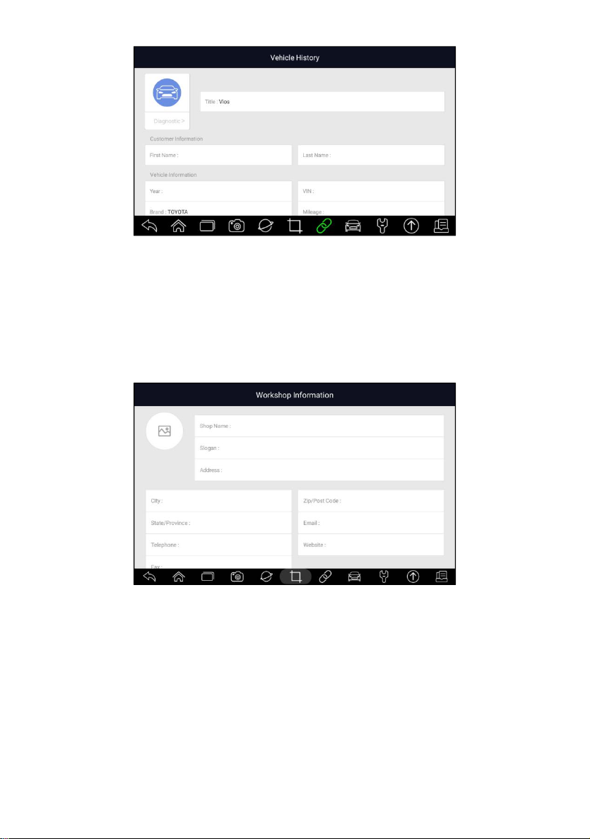
Figure 11-2 Sample Vehicle History Screen
11.2 Workshop Information
The Workshop Information allows you to edit, input and save the detailed
workshop information, such as shop name, slogan, address, phone number
and more. It will show as the header of the printed documents when printing
vehicle diagnostic reports and other test files.
Figure 11-3 Sample Workshop Information Screen
12 My Account
This section displays the information related to your account and product.
When My Account application is selected, a menu with available options
displays. Menu options typically include:
●
My Account
● My Products
● Push Message
● Complaints
Premier Diagnostic Platform i70Pro User's Manual V1.01
80
Page 81
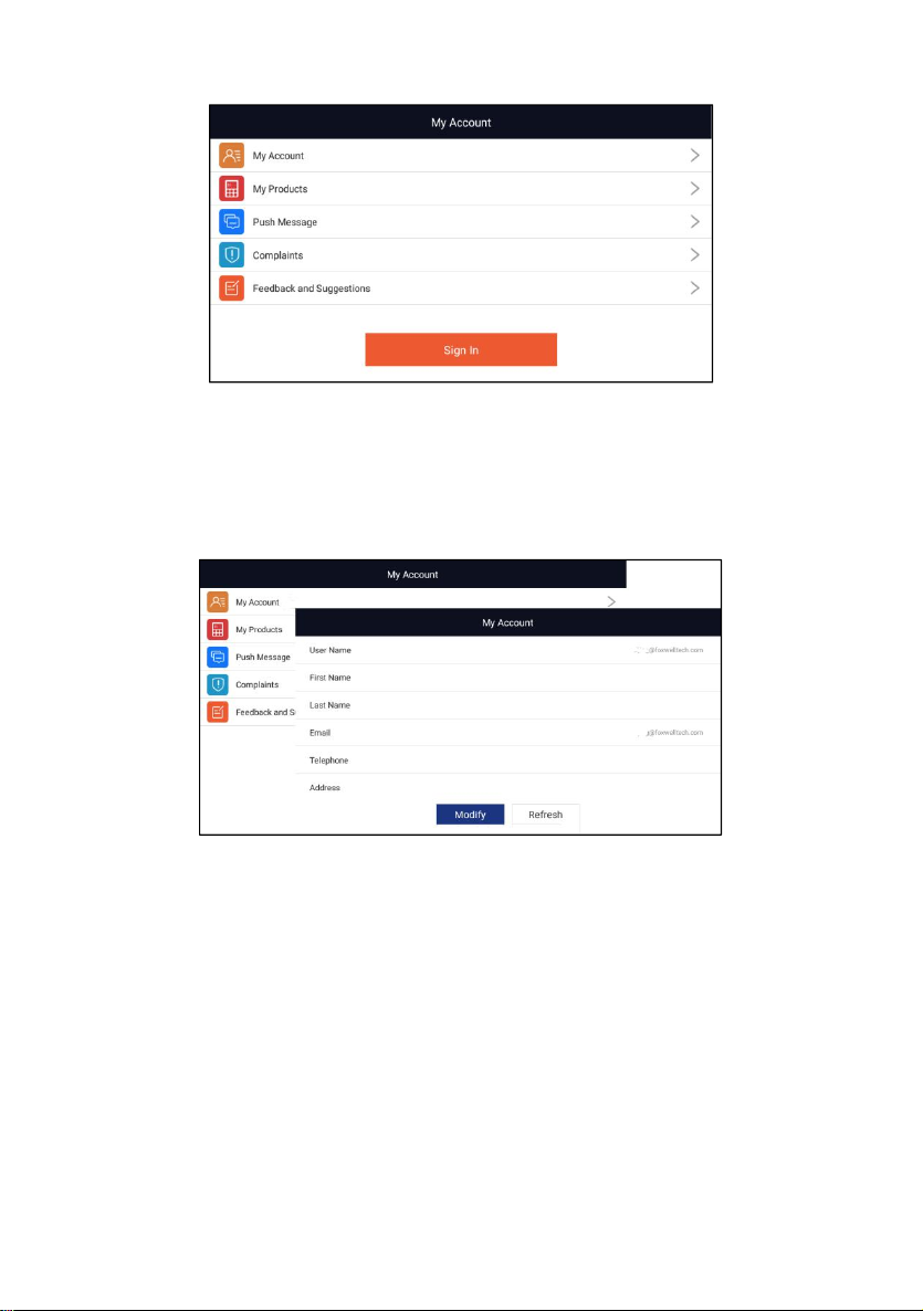
● Feedback and suggestions
Figure 12-1 Sample My Account Screen
12.1 My Account
My Account option allows you to check and modify your account information
including user name, e-mail, telephone, address and so on.
Figure 12-2 Sample My Account Screen
12.2 My Products
This option let you activate a new product and manage activated products
including serial number and expiration date.
Premier Diagnostic Platform i70Pro User's Manual V1.01
81
Page 82
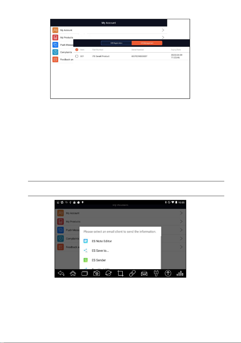
Figure 12-3 Sample My Products Screen
12.3 Push Message
It will display all messages you got from Foxwell including software update
notice and product news.
12.4 Feedback and suggestions
This option allows you to log on your e-mail and send feedback and
suggestions about Foxwell products.
NOTE
Please download e-mail client on the i70Pro before using this function.
Figure 12-4 Sample Feedback & Suggestions Screen
Premier Diagnostic Platform i70Pro User's Manual V1.01
82
Page 83
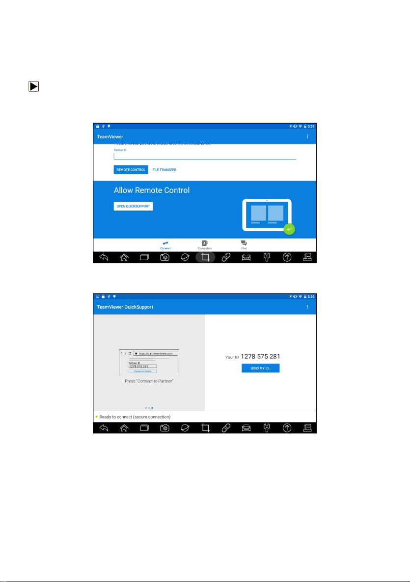
13 Remote Support
Remote Control enables you to get remote support from Foxwell with
TeamViewer when you have issues with Foxwell products.
If you need our team to remote control your i70Pro,
1. Click the Remote Control icon on the main menu of the i70Pro to start
TeamViewer.
Figure 13-1 Sample Remote Control Screen
2. Press QuickSupport icon and the TeamViewer ID will show.
Figure 13-2 Sample QuickSupport Screen
3. Send your ID to us to let our team to take control your tablet.
14 Technical Data
This option provides you with the quick access to technical data like wiring
diagram and repair tips provided by HaynesPro, AutoData or others.
Premier Diagnostic Platform i70Pro User's Manual V1.01
83
Page 84
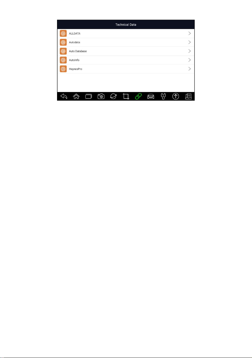
Figure 14-1 Sample Technical Data Screen
Premier Diagnostic Platform i70Pro User's Manual V1.01
84
 Loading...