


Fox Thermal
THERMAL MASS FLOW METER & TEMPERATURE TRANSMITTER
Model FT3
Mass Flow
An
ON
ICON
Brand
www.foxthermal.com | 399 Reservation Road Marina, CA. 93933
104488 Rev. G

Model FT3 
Notice
FOX THERMAL
This publication must be read in its entirety before performing any operation. Failure to understand and follow these instructions could result in serious personal injury and/or damage to the equipment. Should this equipment require repair or adjustment beyond the procedures given herein, contact the factory at:
FOX THERMAL INSTRUMENTS, INC.
399 RESERVATION ROAD
MARINA, CA 93933
TELEPHONE: 831-384-4300
FAX: 831-337-5787
EMAIL: SERVICE@FOXTHERMAL.COM
Download Technical Data Sheets from our website:
www.foxthermal.com
Fox Thermal Instruments (Fox Thermal) believes that the information provided herein is accurate; however, be advised that the information contained herein is NOT a guarantee for satisfactory results. Specifically, this information is neither a warranty nor guarantee, expressed or implied, regarding performance, merchantability, fitness, or any other matter with respect to the products; nor recommendation for the use of the product/process information in conflict with any patent.
Please note that Fox Thermal reserves the right to change and/or improve the product design and specification without notice.
All Fox Thermal Manuals and software available in English only.
2

Table Of Contents
1. |
Introduction |
Page 4 |
2. |
Installation (Mechanical) |
Page 8 |
|
a. Insertion Type |
Page 8 |
|
b. Inline Type |
Page 12 |
3. |
Wiring (Electrical) |
Page 14 |
|
a. General |
Page 14 |
|
b. Signal Wiring |
Page 14 |
|
c. Input Power |
Page 16 |
|
d. Alarm Wiring |
Page 21 |
|
e. Remote Switch |
Page 23 |
|
f. Remote Wiring |
Page 24 |
4. |
Operation (Standard Operation) |
Page 26 |
|
a. Start Up |
Page 26 |
|
b. Display Screens |
Page 27 |
|
c. Engineering Screens |
Page 28 |
|
d. Programming |
Page 29 |
|
e. Menu Trees |
Page 54 |
5. |
Maintenance |
Page 60 |
|
a. Troubleshooting |
Page 63 |
6. |
Dimensions |
Page 70 |
7. |
Appendices |
Page 78 |
|
a. Specifications |
Page 78 |
|
b. Agency Approvals |
Page 80 |
|
c. FT3 with 2 Gas Curves |
Page 82 |
|
d. Installation Variations |
Page 86 |
|
e. Returning your meter |
Page 88 |
8. |
Warranty |
Page 89 |
9. |
Glossary of Terms and Abbreviations |
Page 90 |
10. Index |
Page 92 |
|
 Model FT3
CONTENTS OF TABLE
3

INTRODUCTION
Model FT3 
Introduction
Thank you for purchasing the Model FT3 Thermal Gas Mass Flow Meter and Temperature
Transmitter from Fox Thermal. The Model FT3 is one of the most technically advanced flow meters in the world. Extensive engineering effort has been invested to deliver advanced features, accuracy measurement performance and outstanding reliability.
This Instruction Manual contains the electrical and mechanical installation instructions as well as details for programming, maintaining and troubleshooting the meter.
This manual is divided into the following sections: Introduction, Installation, Wiring, Operation, Maintenance, Troubleshooting, Appendices, Glossary and Index.
Theory of Operation
The Model FT3 is an innovative Thermal Mass Gas Flow Meter and Temperature Transmitter.
It is microprocessor-based and field programmable. The FT3 thermal sensor operates on the law that gases absorb heat. A heated sensor placed in an air or gas stream transfers heat
in proportion to the stream’s mass velocity. There are two sensor elements connected to a balanced bridge circuit. One sensor element detects the gas temperature and a second element is maintained at a constant temperature above the gas temperature. The energy
applied to the heated sensor to maintain a constant temperature differential (constant ∆ T) is directly proportional to the mass flow velocity. The FT3 flow meter maintains accurate flow measurement over a large temperature and pressure range.
Mass Flow
The Model FT3 measures mass flow; an advantage over other flow meters which measure volumetric flow rate. Volumetric flow is incomplete because temperature and pressure are unknown and must be measured separately. For example, the mass flow of a gas depends on its temperature and pressure. As temperature and pressure changes, the gas volume changes but not its mass. Therefore a device measuring mass flow is independent of temperature and pressure. The Model FT3 provides a direct measurement of gas flow in Mass units (kg/ hr, lb/hr), standard units (SCFM, SLPM) or normal units (NM3/hr, NLPM) with no additional temperature or pressure measurements required.
Calibration Validation
Fox Thermal has developed a method to validate the calibration of the flow meter in the field.
This method is called Calibration Validation and it is made up of two distinct tests: CAL-V™ and Zero CAL-CHECK®. The goal of Calibration Validation is to provide operators with the ability to verify that the meter is capturing accurate data at scheduled recalibration times - or at any time - instead of sending the meter back to the factory for recalibration.
By performing CAL-V™ in the field, operators can verify that the meter is running accurately by testing the functionality of the sensor and its associated signal processing circuitry. This test can be done in the pipe and in normal processing conditions. The second test, Zero CAL-
CHECK®, ensures the effectiveness and sensibility of the sensor at a "no flow" condition.
4

 Model FT3
Introduction
Flow Calibration
The Fox Thermal Calibration Lab maintains instrument calibration records on every flow meter.
This data can also be accessed by a computer using FT3 View™ software within the instrument.
Computer-generated calibration documents describe specific instrument details that can be sorted by serial number, tag number or customer purchase order.
Calibration files include details on process conditions, calibration fluid, line size and other information. All NIST-traceable equipment utilized for the calibration procedure is identified, as is the calibration history of all reference equipment. In addition to the Calibration Certificate, a certified flow table that correlates current outputs with scaled units of flow is produced for each calibrated device.
I/O Description
The FT3 features two galvanically isolated 4-20mA analog outputs, one isolated digital output that can be used for frequency or alarm, one programmable contact input and a USB connection for communication with a computer.
The first 4-20mA output is for flow rate. The second 4-20mA output can be configured either for flow rate or process gas temperature. Both 4-20mA outputs can be scaled by the user. The frequency output is programmable to represent flow rate and can be scaled for maximum flow/ maximum frequency, units-per-pulse or pulse-per-units. The maximum frequency is 100 Hz.
An isolated 24VDC output power option is provided for use with these outputs. It can supply a 42mA maximum total load (do not use for other external devices). FT3 View™ interfaces to the USB port and is a free Fox Thermal PC-based software program that displays flow meter readings and permits flow meter configuration. Industry standard communication options are available including HART or RS485 Modbus. Only one of these options can be provided in a single FT3 flow meter.
FT3 Optional Display and Configuration Panel
The configuration panel allows the user to change a variety of settings in the FT3. The display is 2 lines x 16 characters with 4 mechanical and 4 IR (infrared) buttons. The IR and mechanical (push) buttons perform the same function but the IR buttons can be used without opening the cover. The IR buttons can be calibrated (p. 53) for better operation in the field or disabled
(p. 52) when the meter is used in snow or ice in order to avoid false key detection.
Fig. 1.1: FT3 Optional Display and Configuration Panel
Display Window
IR (infrared) Buttons
Push Buttons
INTRODUCTION
5

INTRODUCTION
Model FT3 
Introduction
FT3 Functional Diagram
An optional on-board display is available to view flow rate, total flow, elapsed time, process gas temperature and alarms. The display is also used in conjunction with the Configuration Panel for field configuration of flow meter settings such as 4-20mA scaling, pulse output frequency scaling, pipe area, zero flow cutoff, flow filtering or damping, display configurations, diagnostics and alarm limits.
Fig. 1.2: FT3 Functional Diagram
24VDC Input Power |
|
|
|
Standard I/O |
||
|
|
|
4-20mA Flow |
|||
100-240VAC Optional |
|
|
|
|||
|
|
|
|
|||
Optional Display and |
|
|
|
|
|
4-20mA Flow or Temperature |
|
|
|
|
|
||
Configuration Panel |
|
|
|
|
Frequency or Alarm |
|
|
|
|
|
|||
|
|
|
|
|
|
|
|
|
|
|
|
|
Contact Input |
|
|
|
|
|
|
Standard Digital Communications |
|
|
|
|
|
|
USB |
|
|
|
|
|
||
|
|
|
|
|
|
(Free FT3 View™ Software) |
|
|
|
|
|
|
Optional Serial Communications |
|
|
|
|
|
|
HART |
|
|
|
|
|
|
Modbus RTU (RS485) |
|
|
|
|
|
|
Outputs and Communications are Galvanically Isolated |
6

 Model FT3
Introduction
Scope
This section describes how to install the Fox Thermal Model FT3 Flow Meter and how to get started. Installation methods will vary according to the flow meter type (insertion or inline).
For Insertion Types:
1.Determine lateral position on the pipe
2.Sensor installation depth
3.Sensor orientation in relation to sensor length and direction of flow
4.Proper tightening of compression fitting for mounting meter
For Inline Types:
1.Determine lateral position on the pipe
2.Flow body orientation in relation to direction of flow in pipe
3.Proper tightening of compression fitting
Installation procedures must be performed using a combination of the end user’s best engineering practices, in compliance with local codes, and manufacturer’s recommendations.
General Precautions
The following general precautions should be observed:
1.Exercise care when handling the flow meter to avoid damaging the probe, sensor or enclosure.
2.Close any unused conduit openings in the enclosure with plugs certified for your application.
3.The enclosure covers must be closed except during installation.
4.Mounting FT3 in direct sunlight can cause the temperature inside the enclosure to increase beyond design limits, resulting in failure of LCD display and reduced component life. It is recommended that a sunshade be installed to avoid direct sunlight.
5.Ensure the flow direction arrow points in the direction of flow.
6.Do not install the FT3 enclosure near an igniter, igniter-controller or switching equipment.
7.Do not install an external power supply in a cabinet containing an igniter controller or switching equipment.
8.Ensure that good engineering practices and applicable industry codes are followed throughout the installation process.
9.For accurate flow measurement: review flow meter placement instructions before installation to ensure a proper flow profile in the pipe.
INTRODUCTION
7

INSTALLATION
Model FT3 
Installation
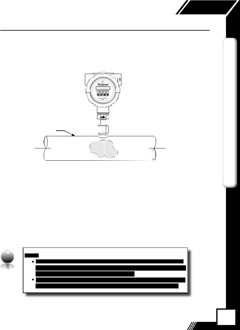
Instructions for Insertion Flow Meter Lateral Placement
Install the Model FT3 Insertion style flow meter so that it is far enough away from bends in the pipe, obstructions, or changes in line sizes to ensure a consistent flow profile. Fifteen diameters of straight pipe upstream and ten downstream are recommended.
For example, a 2" pipe would require 30" upstream and 20" downstream, but a 4" pipe would require 60" upstream and 40" downstream.
I |
NOTE! The probe diameter is ½". |
||
NOTE! Fox Thermal ¼" meters require 6" of straight pipe upstream and downstream of |
|||
|
|
|
the meter's inlet and outlet. |
|
|
|
|
|
|
|
NOTE! Fox Thermal flow meters can be mounted in either horizontal or vertical pipes. |
Fig. 2.1: Upstream and Downstream Pipe IDs for Insertion Meters
Proper
Profile
FLOW
15X Pipe ID |
10X Pipe ID |
 Irregular
Profile
8

 Model FT3
Installation
Installation Depth
The installation depth of the sensor in the pipe is dependent on the pipe size. To get the most accurate reading, proper placement of the sensor window within the pipe is necessary. As shown in Fig 2.2, the end of the sensor window should be 0.87" past the center line of the pipe.
Fig. 2.2: Cross Section of Insertion Sensor Depth in Pipe
INSTALLATION
Half Coupling, |
Compression Fitting |
(Supplied by Fox) |
|
3/4" NPT Female |
|
(Supplied by |
Probe Diameter, 1/2” |
Customer) |
|
|
Customer’s Pipe |
C
L
.87" (22.098 mm)
9

INSTALLATION
Model FT3 
Installation
Fig. 2.3: Orientation of Insertion Type Flow Meter
Flow Direction Arrow

Pipe
FLOW
I |
NOTE! Some flow meters are shipped with the sensor elements that are offset (see |
||
figure 2.4). Others are shipped with sensors that have equal length elements (see figure |
|||
|
|
|
2.5). The sensor type supplied was selected at the factory to be the best suited for your |
|
|
|
|
|
|
|
application. Follow the appropriate sensor orientation instructions. |
Unequal Length Sensor Elements
Install the shorter sensor element upstream from the longer one.
Fig. 2.4: Unequal Length Sensor Elements
+2°
FLOW
-2°
FLOW 
10
 Model FT3
Installation
Equal Length Sensor Elements
Install flow meter with both sensor elements facing the flow stream within ±2˚.
Fig. 2.5: Equal Length Sensor Elements
+2°
FLOW
-2°
FLOW
Insertion Mounting Instructions - Compression Fittings
The Model FT3 is mounted through a ¾" hole and a ¾" female NPT half coupling provided in the customer's pipe. Insertion style flow meters are not designed for use in pipes smaller than
1½".
•Install the compression fitting into the ¾-inch female NPT half coupling.
•When installing in a 2" pipe or larger, install the end of the probe 0.87" past the center line of the pipe and tighten the compression fitting nut (refer to figure 2.2 on p. 9).
•When installing into a 1½" pipe carefully install the probe into the pipe until it touches the opposite wall and pull back 0.1". Tighten the compression fitting nut.
CAUTION! Once the compression fitting is locked onto the probe, the probe can be removed or rotated, but the insertion depth is locked in place.
INSTALLATION
 I
I  NOTE! Do not overtighten compression fitting.
Fig. 2.6: Proper Tightening of the Compression Fitting Nut
While holding the fitting body steady, tighten the nut one and one-quarter turn to the 9
o'clock position.
11

INSTALLATION
Model FT3 
Installation
Instructions for Inline Flow Meter Placement
Install the Model FT3 Inline style flow meter so that it is far enough away from bends in the pipe, obstructions, or changes in line sizes to ensure a consistent flow profile. Eight diameters of straight pipe upstream and four downstream are recommended (for ¼" meters: 6” (152 mm) of straight, unobstructed pipe upstream and downstream are required).
For example, a 2" pipe would require 16" upstream from the edge of the flow body and 8" downstream from the other end of the flow body, whereas a 4" pipe would require 32" upstream and 16" downstream.
The Model FT3 is welded, threaded or flanged to the customer’s pipe. Care should be taken to ensure that the diameter of the mating pipe is the same diameter as the Model FT3 flow body or errors in flow readings can occur. The installation procedure should be a combination of the end user’s best engineering practices, in compliance with local codes, and the manufacturer’s recommendations.
See Figure 2.7 for a detailed look at upstream and downstream pipe diameters for inline meters.
Fig. 2.7: Upstream and Downstream Pipe IDs for Inline Meters
Proper
Profile
FLOW
8X Pipe ID |
4X Pipe ID |
 Irregular
Profile
12
 Model FT3
Installation
Inline Orientation
Install the flow body so that the engraved arrow on the fitting and the arrow on the flow body are pointing with the direction of flow.
Fig. 2.8: Orientation of an Inline Meter - Directional Arrows
Flow Body
FLOW
Tightening Compression Fittings
The compression fitting has been placed according to the proper depth in the flow body by Fox Thermal factory technicians. After the flow body has been correctly fitted to the process pipe, the compression fitting may need to be tightened correctly (see figure 2.6 on p. 11).
INSTALLATION


 I
I


13

Model FT3 
 Wiring
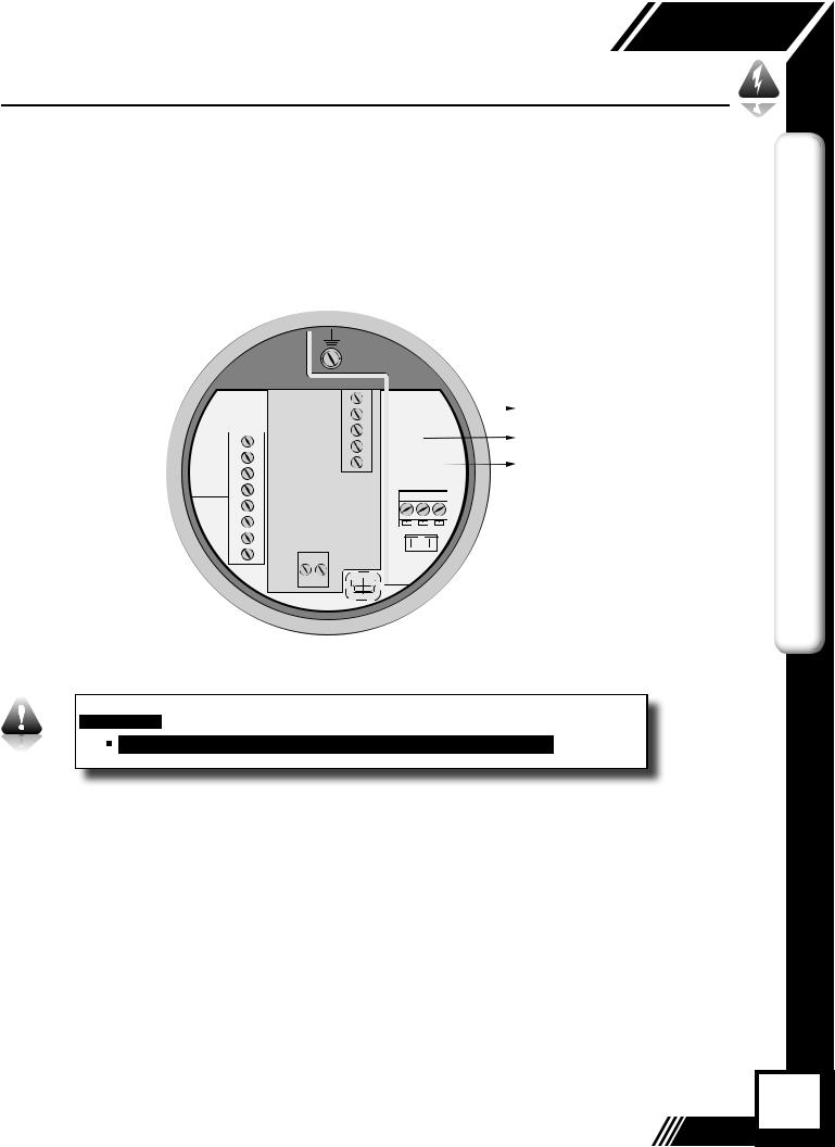
Wiring Instructions
Wire the FT3 by opening the rear enclosure cover, bringing customer supplied wires in through the conduit openings and connecting to the terminal blocks. The FT3 has two conduit openings to maintain separation between AC input power and output signal wiring. To eliminate the possibility of noise interference, use a separate conduit for AC power and cut all wires short for a minimum service loop.
|
Wiring Precautions |
|
WIRING |
• WARNING - DO NOT OPEN THE ENCLOSURE WHEN ENERGIZED OR AN EXPLOSIVE |
|
ATMOSPHERE IS PRESENT. |
||
|
||
|
• All plumbing and electrical installations of flow meters must be in compliance with local |
|
|
codes, the end user’s best engineering practices, and manufacturer’s recommendations. |
|
|
• An external power disconnect and 16A over-current protection are required for the AC |
|
|
and DC powered FT3. |
|
|
• Do not install the FT3 enclosure near an igniter, igniter-controller or switching equipment. |
|
|
• Do not install an external power supply in a cabinet containing an igniter controller or |
|
|
switching equipment. |
|
|
• This flow meter contains components that can be damaged by static electricity. You must |
|
|
discharge yourself by touching a grounded steel pipe or other grounded steel material |
|
|
prior to working inside this flow meter. |
|
|
• For the remote sensor option, the serial number of the electronics enclosure must match |
|
|
the remote sensor probe. |
|
|
• Close any unused entries using suitably certified plugs |
|
|
Power Wiring |
|
|
For power wiring, use stranded copper wire, no larger than 16-gauge. If an external 24VDC |
|
|
power source is used, twisted pair shielded cable is recommended. Supply connection wiring |
|
|
must be rated for at least 90°C. |
|
|
Grounding |
|
|
The enclosure must be properly grounded with a quality earth ground. 16 gauge, stranded |
|
|
wire is recommended. |
|
|
Signal Wiring |
|
|
For signal wiring, the recommended wire gauge is 18 to 22 AWG. Always use twisted pair |
|
|
shielded cable. The cable shield should not be connected at the flow meter, it should be |
|
|
connected at the power supply AC ground terminal or instrumentation AC ground. Do not |
|
|
route the power and signal wires in the same conduit. Power wires must enter left-hand conduit |
|
|
entry. Signal and remote sensor (where applicable) must enter right-hand conduit entry. |
14

 Model FT3
Wiring
Serial Communication Wiring
If you have purchased communications options, please refer to one of the following appropriate Fox Thermal Instruction Manuals:
•Fox Thermal FT3 RS485 Modbus Manual
•Fox Thermal FT3 HART Manual
FT3 Wiring
Fig. 3.1: FT3 Wiring
Input |
Signal Wiring, |
|
Power |
||
Serial Communication |
||
|
3x 3/4 inch NPT Female
Flow Meter Probe or
Remote Sensor Wiring
WIRING
I |
NOTE! Remote wiring is only required when the Remote Electronics options is |
|||
provided. Five wire shielded cable required, the recommended wire gauge is 18 AWG. |
||||
|
|
|
||
|
|
|
Make sure that the cable length does not exceed 100 feet and the wire resistance does |
|
|
|
|
||
|
|
|
not exceed one ohm. Do not connect the cable shield at the electronics enclosure end. |
|
15

Model FT3 
 Wiring
WIRING
Power Input Requirements: 24VDC Supply
External DC power supply must provide 24VDC ± 10%, at 0.7 Amps minimum.
The enclosure must be properly grounded with a quality earth ground. Sixteen (16) gauge, stranded wire, is recommended for power and earth ground.
Fig. 3.2: Connections for 24VDC Supply
|
TS2 |
|
|
|
|
|
|
Earth Ground |
|
TS3 |
|
|
|
|
|
|
24V Return |
4-20+1 |
REMOTE |
|
|
|
|
|
|
|
SENSOR |
|
|
|
|
|
|
|
|
FLOW-2 |
|
|
|
|
|
|
|
+24VDC |
4-20+3 |
|
|
|
|
|
|
|
|
|
|
|
|
|
|
|
|
|
|
1 |
2 |
3 |
|
||||
#2 -4 |
|
|
||||||
|
|
|
|
|
|
TS1 |
||
+5 |
|
|
|
|
|
|
||
|
|
|
|
|
|
|
|
|
PULSE |
|
|
|
|
|
|
|
|
/ALM-6 |
|
|
|
|
|
|
|
|
+7 |
|
|
|
|
|
|
F1 |
|
IN |
TS4 - |
|
|
|
|
|
|
|
-8 |
|
|
|
|
|
|
|
|
24V |
24V, 0.75A |
|
|
|
||||
|
|
|
|
|||||
|
OUT |
|
|
|
|
|
|
|
|
|
J2 |
|
|
|
|
|
|

 I
I


 NOTE! A power failure or resetting the total will cause the Contract Time to change.
 Data Logger with a Real Time Clock (RTC) option should be used to avoid this.
16
 Model FT3
Wiring
Power Input Requirements: 100 to 240VAC Supply
If the FT3 has the AC power supply option, the AC power must provide 100 to 240VAC -15% / +10% (85 to 264VAC) at 0.2 Amps minimum.
The enclosure must be properly grounded with a quality earth ground. Sixteen (16) gauge, stranded wire, is recommended.
Fig. 3.3: Connections for optional AC Power
|
TS2 |
|
|
|
|
|
Earth Ground |
|
|
|
|
|
|
||
|
TS3 |
|
|
|
|
|
|
+1 |
REMOTE |
|
|
|
|
|
AC (L) |
4-20 |
SENSOR |
|
|
|
|
|
|
FLOW-2 |
|
|
|
|
|
|
AC (N) |
4-20+3 |
|
|
|
|
|
|
|
|
|
|
|
|
|
|
|
|
1 |
2 |
3 |
|
|||
#2 -4 |
|
|
|||||
|
|
|
|
|
TS1 |
||
+5 |
|
|
|
|
|
||
|
|
|
|
|
|
|
|
PULSE |
|
|
|
|
|
|
|
-6 |
|
|
|
|
|
|
|
+7 |
|
|
|
|
|
F1 |
|
IN |
TS4 - |
|
|
|
|
|
|
-8 |
|
|
|
|
|
|
|
24V |
24V, 0.75A |
|
|
|
|||
|
|
|
|
||||
|
OUT |
|
|
|
|
|
|
|
|
J2 |
|
|
|
|
|
WIRING
17

Model FT3 
 Wiring
WIRING
4-20mA Output Wiring: Customer-Supplied Power Source
Bring the 4-20mA wiring in through the right-hand conduit hub. Connect FLOW RATE 4-20mA wiring to TS2, 1(+) & 2(-). Connect 4-20mA output #2 wiring to TS2, 3(+) & 4(-).
CAUTION! When using the 4-20mA output to control equipment in a failsafe application, see the wiring configuration on p. 20.
Fig. 3.4: 4-20mA Output Wiring for Customer-Supplied Power Source
|
|
FT3 |
Customer PLC or DCS |
|
|
TS2 |
+24VDC |
||
|
|
TS3 |
||
|
|
|
|
|
4-20+1 |
|
REMOTE |
|
|
|
SENSOR |
|
4 to 20mA FLOW RATE |
|
FLOW-2 |
|
|
|
* (see important note below) |
|
|
|
||
4-20+3 |
|
|
1 2 3 |
|
#2 -4 |
|
|
||
+5 |
|
|
|
24VDC Return TS1 |
PULSE |
|
|
|
|
/ALM-6 |
|
|
+24VDC |
|
+7 |
|
|
|
F1 |
IN |
|
TS4 +1 |
|
4 to 20mA TEMPERATURE OR |
-8 |
|
|
||
|
24V |
|
||
|
|
OUT |
|
24V, 0.75A FLOW RATE |
* (see important note below)
J2
24VDC Return


 I
I


18
 Model FT3
Wiring
4-20mA Output Wiring: Loop Power Provided by FT3
Bring the 4-20mA wiring in through the right-hand conduit hub. Connect the 4-20mA wiring to terminal blocks TS2 and TS4 as shown in the diagram below.
CAUTION! When using the 4-20mA output to control equipment in a failsafe application, see the wiring configuration on p. 20.
Fig. 3.5: 4-20mA Output Wiring for Loop Power Provided by FT3
|
|
FT3 |
|
Customer PLC or DCS |
|||
|
TS2 |
|
|
|
|
|
|
+1 |
|
TS3 |
|
|
|
|
|
4-20 |
|
REMOTE |
|
4 to 20mA FLOW RATE |
|||
FLOW |
|
SENSOR |
+ |
||||
-2 |
|
|
|
|
- |
* |
(see important note below) |
4-20+3 |
|
|
|
|
|||
|
|
|
|
+ |
|
1 2 3 |
|
#2 -4 |
|
|
|
|
|
||
|
|
|
|
- |
* |
(see important noteTS1below) |
|
+5 |
|
|
|
|
|||
|
|
|
|
|
4 to 20mA TEMPERATURE |
||
PULSE |
|
|
|
|
|
||
/ALM-6 |
|
|
|
|
|
|
OR FLOW RATE |
+7 |
(-)2 |
(+)1 |
|
|
F1 |
||
IN |
|
|
|
||||
-8 |
|
TS4 |
+1 |
|
|
24V, 0.75A |
|
|
TS4 |
|
|
|
|
||
|
|
|
|
|
|
||
|
|
24V |
|
|
|
|
|
|
|
OUT |
|
|
|
|
J1 |
|
|
|
|
|
|
|
|
WIRING

 I
I


 NOTE! This wiring option is only available with the isolated 24V ouput power option.


 I
I


19

Model FT3 
 Wiring
WIRING
Setting Up the NE-43 Alarms
The FT3 flow meter supports the NAMUR specification NE-43 for alarms on the 4-20 mA output. See p. 31 for the 4-20mA output NAMUR operation.
CAUTION! Configure the FT3 with the following setup when using the 4-20mA output to control equipment in a failsafe application.
4-20mA Failsafe Wiring: NAMUR NE-43
When the 4-20mA output is used to control equipment in failsafe applications:
•Wire the 4-20mA output in series with the Alarm output as shown in Fig. 3.6
•Configure the Pulse/Alarm output to Alarm and select System Alarm as shown in the
"Alarm Output" on page 34.
The System Alarm output is designed to allow current to flow during normal operation and interrupts current when power to the meter is lost or in a System Alarm condition.
In the 4-20mA Failsafe Wiring configuration of Fig. 3.6, the 4-20mA signal goes to 0mA if power to the FT3 is lost or a System Alarm occurs.
Fig. 3.6: 4-20mA Failsafe Wiring and Range of 4-20mA Output for NAMUR Alarm
FT3  Customer PLC or DCS
|
TS2 |
|
+24VDC |
||
|
|
TS3 |
|
||
|
|
|
|
|
|
4-20+1 |
|
REMOTE |
|
|
|
|
SENSOR |
|
|
||
FLOW-2 |
|
|
|
|
|
4-20+3 |
|
|
|
1 2 3 |
|
#2 -4 |
|
|
|
||
+5 |
|
|
|
|
TS1 |
|
|
|
|
|
|
PULSE |
|
|
|
|
|
/ALM-6 |
|
|
|
|
4 to 20mA FLOW RATE |
|
|
|
|
||
+7 |
|
|
|
|
|
|
|
|
|
F1 |
|
IN |
|
TS4 |
+1 |
|
24VDC Return |
-8 |
|
|
|||
|
24V |
|
|
||
|
|
|
|
24V, 0.75A |
|
|
|
OUT |
|
|
|
|
|
|
|
|
J2 |
NAMUR |
Range |
Alarm |
|
|
|
Working Range Normal Operation |
|
|
|
NAMUR |
Range |
Alarm |
|
21 mA
20 mA
4 mA
3.6 mA
0 mA
20
 Model FT3
Wiring
Frequency/Alarm Output Wiring
Bring frequency/alarm wiring in through the right-hand conduit hub. Connect to TS2, 5(+) & 6(-). The frequency/alarm output is an open collector circuit capable of sinking a maximum of
20mA of current. Frequency or Alarm selection is programmed using the display. Only one option, frequency or alarm, can be active at a time.
Fig. 3.7: Frequency/Alarm Output Isolated (Recommended)
FT3 |
Customer PLC or DCS |
TS2 |
TS3 |
|
|
|
|
|
|
4-20+1 |
|
REMOTE |
|
|
|
|
|
|
SENSOR |
|
|
+24VDC |
|||
FLOW-2 |
|
|
|
|
|
|
|
4-20+3 |
|
|
1 |
2 |
3 |
2.4K to 10K OHM |
|
#2 -4 |
|
|
|||||
|
|
|
|
|
|
||
+5 |
|
|
|
|
|
|
TS1 |
|
|
|
|
|
|
|
|
PULSE |
|
|
|
|
|
Frequency or Alarm Output |
|
/ALM-6 |
|
|
|
|
|
||
|
|
|
|
F1 |
|||
+7 |
|
|
|
|
|
||
IN |
TS4 +1 |
|
|
24VDC Return |
|||
-8 |
|
|
|
||||
|
24V |
24V, 0.75A |
|||||
|
|
||||||
|
|
OUT |
|
|
|
|
|
|
|
|
J1 |
|
|
|
|
WIRING


 I
I


21

Model FT3 
 Wiring
WIRING
Fig. 3.8: Frequency/Alarm Output Local +24V Power Option
|
|
|
FT3 |
|
|
Customer |
PLC or DCS |
|||||
|
TS2 |
|
|
|
|
|
|
|
|
|
|
|
|
|
TS3 |
|
|
|
|
|
|
|
|
|
|
4-20+1 |
|
REMOTE |
|
|
|
|
|
|
|
|
|
|
|
SENSOR |
|
|
|
|
|
|
|
|
|
|
|
FLOW-2 |
|
|
|
|
|
|
|
2.4K to 10K OHM |
|
|||
|
|
|
|
|
|
|
|
|||||
4-20+3 |
|
|
|
|
|
|
|
|
||||
|
|
|
|
1 |
2 |
3 |
|
|
|
|
||
#2 -4 |
|
|
|
|
|
|
|
|
||||
|
|
|
|
|
|
|
+TS1 |
|
||||
+5 |
|
|
|
|
|
|
|
|
||||
|
|
|
|
|
|
|
|
|
|
|
|
|
PULSE |
|
|
|
|
|
|
|
|
|
|
Frequency |
or Alarm Output |
/ALM-6 |
|
|
|
|
|
|
|
|
|
|
||
|
|
|
|
|
|
|
|
|
|
|||
|
|
|
|
|
|
|
F1 |
|
||||
+7 |
|
|
(-)2 (+)1 |
|
|
|
|
|||||
IN |
|
TS4 +1 |
TS4 |
|
|
|
|
|
|
|
|
|
-8 |
|
|
|
|
|
|
|
|
|
|||
|
|
24V |
24V |
24V, 0.75A |
|
|||||||
|
|
OUT |
OUT |
|
|
|
|
|
|
|
|
|
|
|
|
|
|
|
|
|
|
|
|
||
|
|
|
|
J1 |
|
|
|
|
|
|
|
|
|
|
|
|
|
|
|
|
|
|
|
|
|
22

 Model FT3
Wiring
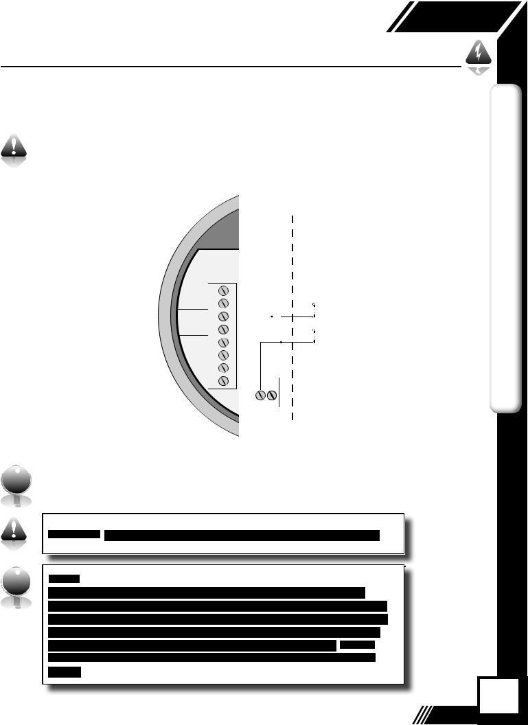
Remote Switch Wiring
A remote switch can be used to reset the Totalizer and elapsed time, if enabled in the programming settings. There is no polarity requirement on these connections. Use TS2, 7(+) & 8(-).
When the 2 gas curve option is ordered, the switch can be used to switch between curves.
Fig. 3.9: Remote Switch Wiring
|
|
|
|
|
|
|
|
|
|
FT3 |
|
Customer PLC |
|||
|
|
|
|
|
|
|
|
|
|
|
|||||
|
|
|
|
|
|
|
|
|
|
|
|||||
|
|
|
|
|
|
|
|
|
or DCS |
||||||
TS2 |
|
|
|
|
|
|
|
|
|
||||||
4-20+1 |
|
|
|
|
|
|
|
|
|
|
|
|
|
|
|
|
|
|
|
|
|
|
|
|
|
|
|
|
|
|
|
FLOW-2 |
|
|
|
|
|
|
|
|
|
|
|
|
|
|
|
4-20+3 |
|
|
|
|
|
|
|
|
|
|
1 |
2 |
|
3 |
|
#2 -4 |
|
|
|
|
|
|
|
|
|
|
|
||||
|
|
|
|
|
|
|
|
|
|
|
|
|
|
TS1 |
|
+5 |
|
|
|
|
|
|
|
|
|
|
|
|
|
|
|
|
|
|
|
|
|
|
|
|
|
|
|
|
|
|
|
PULSE |
|
|
|
EXTERNAL |
|||||||||||
/ALM |
|
|
|
||||||||||||
-6 |
|
|
|
|
|
|
|
|
|
|
|
|
SWITCH |
||
+7 |
|
|
|
|
|
|
|
|
|
|
|
|
|
|
F1 |
IN |
|
|
|
|
|
|
|
|
|
|
|
|
|
|
|
-8 |
|
|
|
|
|
|
|
|
|
|
|
24V, 0.75A |
|
|
|
|
|
|
|
|
|
|
|
|
|
|
|
|
|
||
|
|
|
|
|
|
|
|
|
|
|
J1 |
|
|
|
|
|
|
|
|
|
|
|
|
|
|
|
|
|
|
|
|
WIRING


 I
I


23

Model FT3 
 Wiring
WIRING
Remote Wiring
Remote wiring will be the same for both insertion and inline type FT3 flow meters.
Fig. 3.10: Remote Wiring
2X 3/4 " NPT, |
|
Signal Wiring |
|
|
|
Female |
|
|
Input |
|
|
Power |
|
|
|
|
|
|
|
|
Remote Cable, 5 Conductor,
Shielded, 100ft (30.48m) Max.
Signal Wiring includes:
4-20mA, pulse, alarm output, contact input, remote switch, USB, and communications options.
Power input is 24VDC or optional 100 to 240VAC (+10%/-15%).
I |
NOTE! Remote wiring is only required when the Remote Electronics option is |
||
provided. |
|||
|
|
|
|
Five wire shielded cable required. The shielded cable should be run through a separate grounded steel conduit (no other cables or wires in the conduit). If you are using your own cable, make sure that the cable length does not exceed 100 feet and has a wire resistance that does not exceed one ohm (18 AWG recommended).
 Do not connect the cable shield at the electronics enclosure end.
Use an extension cable to connect the terminals of the remote probe enclosure to connector TS3 of the electronics enclosure as shown in Figure 3.10 and Table 3.1 (p. 25).
24

 Model FT3
Wiring
Fig. 3.11: Remote Sensor Wiring
|
|
|
|
|
|
|
|
|
|
Shield |
#4 |
#2 |
BLK |
|
|
|
|
|
|
|
|
|
|
|
|
||
|
|
|
|
|
|
|
|
|
Cable Shield |
|
GRN |
RED |
|
|
|
|
|
|
|
|
|
|
|
GRN #6 |
WHT |
||
|
|
|
|
|
|
|
|
|
|
|
|
||
|
RED |
|
|
|
1 |
|
|
|
|
|
|
||
|
RED |
|
|
|
2 |
|
|
|
|
|
|
||
|
YEL |
|
|
|
3 |
|
|
|
|
|
|
||
|
WHT |
|
|
|
4 |
|
|
|
|
|
|
||
|
WHT |
|
|
|
5 |
|
|
|
|
|
|
||
|
|
|
|
|
|
TS3 |
1 |
2 |
3 |
|
|
|
|
|
|
|
|
|
|
|
|
|
|
|
|||
|
|
|
|
|
|
|
|
|
TS1 |
|
|
|
|
|
- |
|
|
|
|
|
|
|
F1 |
|
|
|
|
TS4 |
|
|
|
|
|
24V,0.75A |
|
|
|
|
|||
24V |
|
|
|
|
|
|
|
||||||
OUT |
|
|
|
|
|
Black Dot Denotes Pin #1 |
J2 |
|
|
|
|
|
|
|
|
|
|
|
||
|
|
|
|
|
|
|
Electronics Enclosure |
|
|
|
Sensor Wires |
||
|
|
|
||||
|
|
|
|
|
Probe Sensor Wired By Fox |
|
|
|
|
|
|
|
|
|
Remote Enclosure |
|||||
*Wire colors listed here represent the wire colors of cables supplied by Fox Thermal. Colors may vary if customer is supplying their own cable.
Table 3.1: Remote Sensor Cable Wiring
WIRING
25

OPERATION
Model FT3 
Operation
Start Up Sequence
The program automatically enters the Run/Measure mode after power up. If the Local display is installed, the screen will show the software versions for the FT3 and the display module during power up. Programming of the flow meter can also be accomplished using a Windowsbased PC program called FT3View™.
USB Interface
The USB interface is a standard feature which allows communication to a PC in order to monitor readings and configure settings. FT3View™, is a free application program from Fox Thermal that connects to the USB interface and allows data monitoring, configuration setting, data logging to Excel, and an option to save and recall FT3 configuration data. A serial communication manual is available for users who want to create their own PC application.
FT3 Optional Display Panel & Configuration Panel
The FT3 display is a 2 line x 16 character display with 4 mechanical and 4 IR (infrared) buttons. The IR and mechanical buttons perform the same function but the IR buttons can be used without opening the cover. The IR buttons can be calibrated (p. 53) for better operation in the field or disabled (p. 52) when the meter is used in snow or ice in order to avoid false key detection.
Fig. 4.1: FT3 Optional Display and Configuration Panel
Display Window 

IR (infrared) Buttons 

Push Buttons
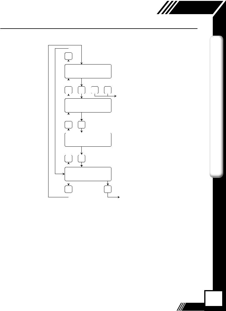
Measurement Mode
In the measurement mode, there are four different display screens (display 1, 2, 3 and a prompt screen to enter the programming mode), two display screens are user programmable (refer
to Display Setup p. 36). Scrolling through the display is accomplished by pressing the F1 or F2 key to view the next or previous screen. Pressing the F1 and F2 keys at the same time
enters the Engineering Menu screens (display 10 through 26). Keys F1 and F2 are used to scroll through the different screens and key F4 in order to exit to Display #1. Pressing the F3 and F4 keys at the same time brings up the Reset Total screen (see p. 45) prompt.
26
Operation
Fig. 4.2: FT3 Display Screen Navigation
|
F1 |
|
|
|
|
Display #1 |
1456.5 SCFM |
|
|
||
123456 SCF |
|
|
|||
|
|
|
|||
|
F1 |
F2 |
F3 |
F4 |
|
Display #2 |
Elp = 14.6 HR |
|
|
||
88.5˚ F |
|
|
|
||
|
|
|
|
||
|
F1 |
F2 |
|
|
|
Display #3 |
Alarm = None |
|
|
||
Elp = 14.6 HR |
|
|
|||
|
|
|
|||
|
F1 |
F2 |
|
|
|
|
|
|
|
||
|
|
|
|
|
|
Display #4 |
Set Parameter? |
|
|
||
No |
|
|
Yes |
||
|
|
|
|||
|
F2 |
|
|
F4 |
|
|
Model FT3 |
F1 key: Moves up one screen |
|
F2 key: Moves down one screen |
|
(User programable screen) |
OPERATION |
Enter “totalizer reset screen” |
|
when F3 & F4 are pressed at |
|
the same time |
|
(User programable screen) |
|
(Fixed screen) |
|
(Fixed screen) |
|
Enter programming screen |
|
Requires password. |
|
Default is 1234. |
|
27

OPERATION
Model FT3 
Operation
FT3 Engineering Displays
Pressing the F1 & F2 keys at the same time in the normal mode, brings up the engineering displays. These displays show internal parameters of the FT3 which are used by Fox Thermal service technicians.
Press F4 to exit. Use the F1 & F2 keys to navigate.
Fig. 4.3: FT3 Engineering Displays
Flow in selected unit |
3124.6 SCFM |
Sensor voltage in volts |
csv=0.3432 Volt |
Sensor average volts |
|
CsvAv=366809 |
|
Velocity in selected unit |
Vel=112345.7 FT/M |
Sensor filtered average in volts |
FloFlt=3666805.3 |
Velocity in Meter/Hour |
Vel=2356.45 M/H |
TSI average count |
TsiAvr=512.5 cnt |
TSV average count |
TsvAvr=323.7 cnt |
TSI in volts |
Tsi= 2.1345 Volt |
TSV in volts |
Tsv=0.9856 Volt |
TSI current in Amp |
Tsi = 0.0435 Amp |
TSI resistance in Ohm |
Tsi = 221.5 Ohm |
RTD9 count |
RTD9= 345.5 cnt |
Gas Temperature in C |
Gas Temp=123.7 °C |
CH1 4-20ma current loop count |
CH1_420=2167 cnt |
CH2 4-20 ma current loop count |
CH2_420=1234 cnt |
Frequency output count |
|
Feq=1234.5 cnt |
|
Alarm codes |
Alarm=33,35 |
High flow limit alarm |
FloHi= 1234 SCFM |
Low flow limit alarm |
FloLo=0 SCFM |
High temperature limit alarm |
TmpHi=300 °C |
Low temperature limit alarm |
TmpLo=10 °C |
Elapsed time in hour |
Elp=12.5 HR |
Status in hexadecimal |
Stat(hex)=2800 |
FT3 main board firmware revision |
FT3 V3.02d |
FT3 display board firmware revision |
Display V2.03b |
Power cycle count |
Pwr_Cycl=24 |
Error with totalizer count |
Err_tot=0 |
TSI resistance in ohm |
Tsi=221.5 Ohm |
RTD9 resistance in ohm |
RTD9=10.3 Ohm |
CAL-V™ Value |
CAL V=23.51 |
CAL-V™ last verify value |
CAL V Chk=0.2% |
Bridge shutdown detection count |
BrShtDnCnt=0 cnt |
|
|
Zero CAL-CHECK® Pipe Ref |
ZRO_Pref=xx.xxxx |
Zero CAL-CHECK® % difference |
ZRO_diff=x.xx% |
Zero CAL-CHECK® Bottle Ref |
ZRO_Bref=xx.xxxx |
Zero CAL-CHECK® % difference |
ZRO_diff=x.xx% |
|
|
28

 Model FT3
Operation
Data Entry using the local display module
There are 2 basic types of menu entries: one for changing value or string and one for selecting from a selection list.
To Change a Value or String :
VALUE = 0.91234 |
|
CHG |
OK |
F1 F2 F3 F4
Press CHG (F1) key to change the value, OK (F4) to accept the value.
VALUE = 0.91234
UP DN NXT OK
F1 F2 F3 F4
Press the UP (F1) or DN (F2) key to select a new digit or character, the cursor points to the selected digit. Press NXT (F3) to select the next digit and OK (F4) to accept the entry.
 I
I 
 NOTE! If the UP (F1) or DN (F2) key is held down for more than 1 second, the program


 will progressively select new digits at increasing speed as time increases.
To Select from a List:
FLO UNT = SCFM |
|
NXT |
OK |
F1 F2 F3 F4
Press NXT (F1) key repeatedly until the correct selection is made and OK (F4) key to accept the entry.
Entering the Programming Mode
To enter the programming mode, press the F1 or F2 key repeatedly in the normal running mode until the following screen is shown:
SET PARAMETERS ?
No Yes
F1 F2 F3 F4
Press YES (F4) and the following screen will prompt the user to enter the password if it is active:
PASWD:_ |
|
|
|
UP |
DN |
NXT |
OK |
F1 |
F2 |
F3 |
F4 |
OPERATION
29
 Loading...