

Page 1
Model FT3
®
Thermal Gas
Mass Flow Meter
and Temperature
Transmitter
For Industrial, Environmental,
Energy Monitoring and Process
Control Applications
FM / FMc
ATEX / IECEx
Precision Mass Flow Measurement
An ON
I
CON Brand
399 RESERVATION RD
MARINA, CA 93933
PHONE: 831-384-4300
FAX: 831-337-5786
sales@foxthermal.com
www.foxthermal.com
APPROVED!
Page 2
Smart, Real-Time Mass
Flow Measurement
The Fox Model FT3 measures two
important process variables with a
single instrument, providing isolated
4-20mA and pulse outputs for ow
rate, and a 4-20mA pulse output for
process gas temperature or a second
ow rate output.
Direct mass ow measurement,
exceptional low-ow sensitivity, fast
response, and low maintenance
requirements distinguish the Fox
Model FT3. Virtually immune to
changes in temperature and pressure,
the ow meter delivers repeatable,
accurate mass ow measurement
under varying loads. It’s rugged, no-
moving-parts design is also ideal for
high-vibration industrial environments,
and enhanced EMI immunity makes
it suitable for environments where
electric motors, ignitors or dirty power
may affect instrument performance.
Creative Solutions - Calibration
Validation with Fox Model FT3
Fox Thermal knows that customers
want creative and effective solutions
to some of their common process
problems. Downtime due to
equipment maintenance or calibration
costs money and wastes valuable time.
Calibration Validation of ow meters
in the eld provides assurance of the
functionality of the meter and avoids
the downtime associated with annual
calibrations.
Used in succession, Fox’s CAL-V™
and Zero CAL-CHECK® Tests can
give you the reassurance that your
meter is performing accurately in the
eld without the need to interrupt
ow or send the meter back to the
factory. The tests are quick and easy
to perform at any time and help with
CALIBRATION VALIDATION:
Typical Requirements of Competitive Models
Stop the ow*
Remove meter from pipe*
Disconnect wires from ow meter
Look up data on ow meter’s calibration certicate
Measure electrical characteristics with volt ohm meter
Perform calculations to evaluate ow meter performance
Set process pressure to manufacturer’s calibration pressure
Connect auxiliary test equipment and/or test gases to ow
meter
*When using a packing gland assembly for Zero CAL-CHECK®
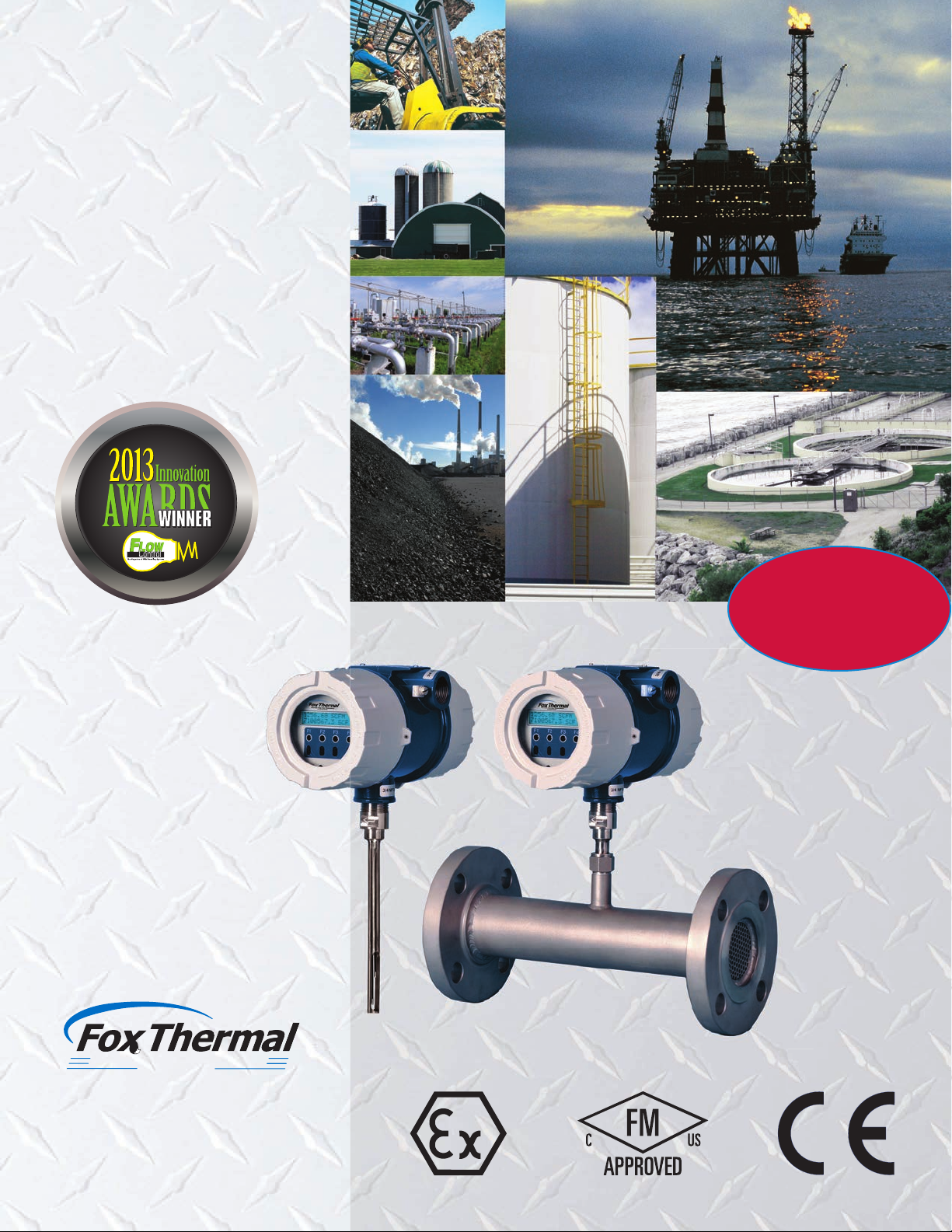
NORMAL MEASUREMENT MODE
Sensor Control Signal
SENSOR
SIGNAL
PROCESSING
ELECTRONICS
PowerPro™ Sensor
In normal measurement mode the signal processing electronics control the sensor.
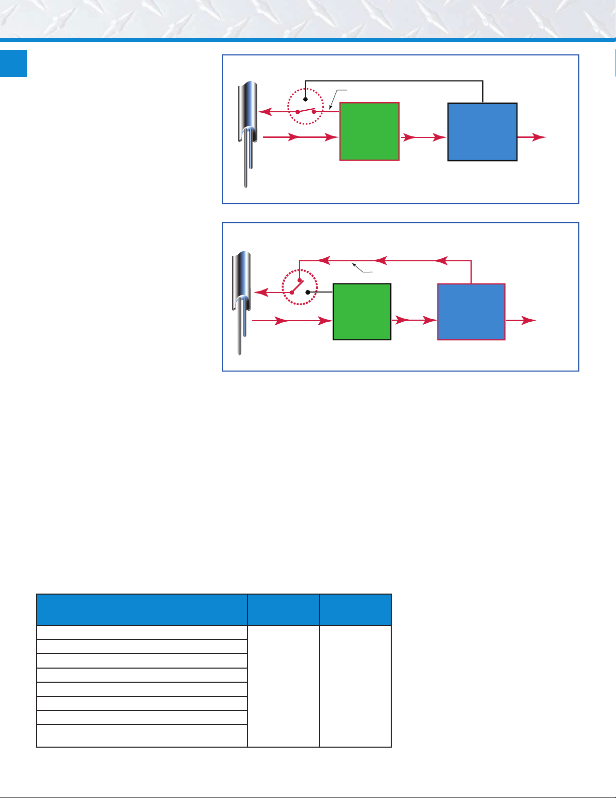
CAL-V™ MODE
Sensor Control Signal
SENSOR
SIGNAL
PROCESSING
ELECTRONICS
PowerPro™ Sensor
In CAL-V™ mode, the microprocessor controls the sensor and determines the resulting electrical
characteristics.
the challenging requirements for
measuring the ow of air and gases.
look-up at any time.
CAL-V™ is an operator-initiated test
MICROPROCESSOR
MASS FLOW
MEASUREMENT
MICROPROCESSOR
CALIBRATION
VALIDATION
Calibration
Validation
PASS/FA IL
that can be performed at any ow rate,
CAL-V™
The CAL-V™ feature is an in-situ
calibration routine that validates the
ow meter’s calibration accuracy by
testing the functionality of the sensor
and its associated signal processing
circuitry. This innovative approach lets
you validate instrument calibration
in the pipe, at process conditions,
with just a push of a button. At the
conclusion of the test, the meter will
display a pass/fail message and the
CAL-V™ data is saved in the meter for
Other Thermal
Flow Meters
FT3 with CALV™ & Zero CALCHECK®
including zero, and is completed in just
three to four minutes. During the test,
the meter’s microprocessor adjusts
the signal to the sensor elements and
determines the resulting electrical
characteristics. These site-determined
characteristics are compared with the
data that was collected and stored in
the instrument electronics during the
original factory calibration. Matching
data within established tolerances
conrms the meter is measuring
accurately.
Zero CAL-CHECK® Tests
The Zero CAL-CHECK® tests are
used to ensure that the ow meter
still retains its original NIST-traceable
calibration at zero ow. The test can
be performed in one of two ways: In-
situ or Out-of-Pipe.
Required Not Required
In-situ Zero CAL-CHECK®
If zero ow can be established, the
sensor does not need to be removed
and the procedure can be done in
the pipe. If zero ow cannot be
established, a Fox Packing Gland
Assembly is used to remove the sensor
Outputs
Page 3

24VDC Input Power
85 to 264VAC Optional
Optional Display
and Configuration
The Model FT3 is a full-featured thermal mass ow meter with a conguration panel that comes
equipped with IR buttons for easy conguration of the meter’s settings.
Panel
from the gas stream to simulate a “no
ow” condition.
The test compares sensor
characteristics at zero ow with
customer-set zero ow baseline
and takes less than ve minutes to
complete after zero ow condition has
been established.
Out-of-Pipe Zero CAL-CHECK®
If zero ow cannot be established and
the meter must be removed from the
pipe, this test may be used. The test
will compare the sensor characteristics
at zero ow at ambient temperature
and atmospheric pressure with the
factory characteristics. This test can
also be performed in less than ve
minutes once the set up is complete.
Easy Accuracy Reporting
Both CAL-V™ and the Zero CALCHECK® Tests can be initiated from
the front panel, USB connection,
Modbus RTU (RS485) or HART. If
initiated by Fox’s FT3 View™ software
tool, CAL-V™ or Zero CAL-CHECK®
Calibration Validation Certicates can
be produced at the conclusion of the
tests.
This feature is of particular value
in environmental monitoring
applications, such as ares and vents,
where periodic calibration validation
is mandated. These tests help
operators comply with environmental
mandates and eliminates the cost
and inconvenience of annual factory
calibration. It can also be used
to streamline quality assurance,
improve process initiatives, and apply
Precision Mass Flow Measurement
An ON
I
CON Brand
Rugged, Reliable Performance
The Fox PowerPro™ sensor operates at
a higher power level than competitive
thermal ow sensors resulting in
improved response time and wider
turndown. The PowerPro™ sensor also
provides exceptional accuracy at high
velocities - up to 60,000 SFPM (280
NMPS).
The Model FT3 features a dualcompartment, explosion-proof
electronics enclosure. One
compartment houses the instrument
electronics and the second
compartment is accessible for wiring.
A waterproof seal between the
compartments helps prevent moisture
damage and maintain the integrity of
the instrument electronics.
An optional on-board 2 line x 16
character backlit display is available to
view ow rate, total ow, elapsed time,
process gas temperature and alarms.
The display is also used in conjunction
with the Conguration Panel for eld
conguration of ow meter settings
such as 4-20mA and pulse output
scaling, pipe area, zero ow cutoff,
ow ltering or damping, display
congurations, diagnostics and alarm
limits. Optically activated keys provide
interface to the ow meter without
removing the cover.
The Model FT3 features galvanically-
isolated outputs and enhanced
EMI immunity. A variety of meter
congurations, materials, process
connections and output options offer
improved design exibility, lower cost-
of-ownership and enhanced control
capabilities.
Standard I/O
4-20 mA Flow
4-20 mA Flow or Temperature
Frequency or Alarm
Contact Input
All Outputs are
Galvanically Isolated
Standard Digital Communication
USB (free FT3 View Software)
Optional Digital Communication
HART
Modbus RTU (RS485)
scheduled maintenance procedures.
The Model FT3 is available in both
insertion and inline models. The
insertion meter is easily installed with
a weld-o-let and compression tting.
The inline model is available in ¼-inch
to 6-inch sizes and includes built-in
ow conditioners that eliminate the
need for long, straight pipe runs.
Communications Options
A USB connection is standard on
the Model FT3, and Fox’s free FT3
View™ software provides complete
conguration and remote process
monitoring functions. FT3 View™
lets you adjust meter conguration,
evaluate transmitter alarm conditions,
collect process data, and view
measurements from your PC or
control station. HART and Modbus
RTU (RS485) are available options.
All digital communication is isolated
to provide immunity from electrical
interference.
NIST Traceable Factory Calibration
Fox calibrations are performed
with NIST traceable ow standards.
Whether you require a straightforward
air calibration or a complex mixed
gas calibration, our goal is to achieve
the highest accuracy and the fastest
turnaround time. The Fox Calibration
Lab employs a wide range of gases,
gas mixtures, temperatures, pressures
and line sizes to simulate actual uid
and process conditions. This realworld approach improves installed
accuracy and minimizes measurement
uncertainty.
Built-in ow conditioning improves
measurement accuracy in space-constrained
applications.
Precision Mass Flow Measurement
An ON
I
CON Brand
Page 4

Summary Specications
Performance Specs
Flow Accuracy:
Inline meter: ± 1% of reading ± 0.2% of full scale.
Insertion meter: ± 1% of reading ± 0.2% of full scale.
Straight, unobstructed pipe requirement:
Inline: 8 diameters upstream; 4 downstream.
Insertion: 15 diameters upstream; 10 downstream.
Insertion (¼” size): 6” (152mm) upstream & downstream
Flow Repeatability: ± 0.2% of full scale
Flow Response Time: 0.9 seconds (one time constant)
Temperature Accuracy:
± 1.8° F (± 1.0° C) -40 to 250° F (-40 to 121° C); ± 3.6° F (± 2.0° C), 250 to
650° F (121 to 343° C); 60 SFPM minimum.
Calibration:
Factory Calibration to NIST traceable standards
CAL-V™ & Zero CAL-CHECK
®: In situ, user-initiated calibration validation
Operating Specs
Units of Measurement (eld selectable):
SCFM, SCFH, NMPS, NM3/M, NM3/H, NM3/D, NLPS, NLPM, NLPH, MCFD,
MSCFD, SCFD, MMSCFD, MMSCFM, SMPS, SM3/D, SM3/H, SM3/M, LB/S,
LB/M, LB/H, LB/D, KG/S, KG/M, KG/H, SLPM, SFPM, MT/H
Flow Rates for Insertion Flow Meter:
15 to 60,000 SFPM (0.07 to 280 NMPS) - Air at 70°F (20°C) & 1 ATM
Turndown: up to 1000:1; 100:1 typical
Typical Flow Ranges for Insertion Flow Meters
Pipe size SCFM MSCFD NM³/HR
1.5” (40mm) 0 - 840 0 - 1,220 0 - 1,325
2” (50mm) 0 - 1,400 0 - 2,020 0 - 2,210
2.5”(63mm) 0 - 2,000 0 - 2,880 0 - 3,150
3” (80mm) 0 - 3,100 0 - 4,440 0 - 4,890
4” (100mm) 0 - 5,300 0 - 7,650 0 - 8,360
6” (150mm) 0 - 12,000 0 - 17,340 0 - 18,930
8” (200mm) 0 - 20,840 0 - 30,020 0 - 32,870
10” (250mm) 0 -32,800 0 - 47,250 0 - 51,740
12” (300mm) 0 - 46,600 0 - 67,180 0 - 73,500
Flow Ranges for Inline Flow Meters
Pipe size SCFM MSCFD NM³/HR
0.25” 0 - 7.5 0 - 10.8 0 - 11.8
0.5” 0 - 125 0 - 180 0 - 200
0.75” 0 - 220 0 - 320 0 - 350
1” 0 - 360 0 - 520 0 - 570
1.25” 0 - 625 0 - 900 0 - 990
1.5” 0 - 840 0 - 1,220 0 - 1,325
2” 0 - 1,400 0 - 2,020 0 - 2,210
2.5” 0 - 2,000 0 - 2,880 0 - 3,150
3” 0 - 3,100 0 - 4,440 0 - 4,890
4” 0 - 5,300 0 - 7,650 0 - 8,360
6” 0 - 12,000 0 - 17,340 0 - 18,930
Note: Standard conditions of air at 70°F and one atmosphere. Consult factory for other gases and for
ow ranges above those listed. Inline meters above 5,000 SCFM (7,900 NM3/H) air may require third
party Calibration. Contact Fox.
Gas Pressure (maximum):
Insertion: 500 psig (34.5 barg)
316 SS inline with NPT ends: 500 psig (34.5 barg)
316 SS inline with 150 lb. flanges: 230 psig (16 barg)
CS inline with NPT ends: 300 psig (20.1 barg)
CS inline with 150 lb. flanges: 285 psig (19.7 barg)
Retractor: 125 psig (8.6 barg)
High pressure retractor: NPT 600 psig (41.4 barg), ANSI 150lb flange &
ANSI 300lb flange, no valve supplied.
Notes:
• Check with factory for higher pressure options.
• With teflon ferrule option, gas pressure max: 60psig (4.1 barg)
• Pressure ratings stated for temperature of 100°F (38°C).
Relative Humidity: 90% RH maximum; non-condensing
Temperature (see Agency Approvals table to the right):
ST sensor: -40 to 250°F (-40 to 121°C)
HT Sensor: -40 to 650°F (-40 to 343°C)
Enclosure Ambient Temperature:
Without display or AC power supply: -40 to 158°F (-40 to 70°C)
With display and/or AC power supply: -4 to 158°F, (-20 to 70°C)
Remote sensor junction box: -40 to 212°F (-40 to 100˚C)
Input Power:
– – –
24 VDC
100 to 240VAC~(+10%/-15%), 50-60Hz, 0.2 Amps (with AC power option)
Note: Fluctuations of AC and DC power supply are not to exceed ±10% of rating.
Class I Equipment (Electrical Grounding Required for Safety).
Installation (Over-voltage) Category II for transient over-voltages.
Outputs:
Two isolated 4-20mA outputs (output one is for ow rate and output two is
programmable for ow rate or temperature); fault indication per NAMUR NE43.
Isolated pulse output 0 to 100Hz, 5 to 24 volts p/p for ow (the pulse output can
be used as an isolated solid state output for alarms); 10mA max.
Serial Communication:
USB communication port is standard. The free PC-based software tool - FT3
View™ - provides complete conguration, remote process monitoring, and data
logging functions.
Optional serial communication: HART and Modbus RTU (RS485).
4-20mA Loop Verication:
Simulation mode used to align 4-20mA output with the input to customer’s PLC/
DCS.
± 10%), 0.7 Amps (standard DC power)
—
(
Physical Specs
Sensor Material: 316 stainless steel standard; Hastelloy C276 optional
Enclosure: NEMA 4X (IP67), Aluminum, dual conduit entries with ¾” NPT or
optional M20 x 1.5mm.
Cabling to remote enclosure: 5-conductor, 18 AWG, twisted, shielded, 100 feet
maximum.
Insertion Flow Meter Installation:
Fox-supplied compression tting connects to customer-supplied 3/4” female
coupling welded to pipe.
Dimensions:
www.foxthermal.com/literature/
Agency Approvals
CE: Approved
EMC Directive; 2014/30/EU
Electrical Equipment for Measurement, Control and Lab Use: EN61326-1:2013
Low Voltage Directive (LVD): 2014/35/EU
Product Safety Testing: EN 61010-1: 2010
Pressure Equipment Directive: 2014/68/EU
Weld Testing: EN ISO 15614-1 and EN ISO 9606-1, ASME B31.3
FM/FMc: Approved
Class I, Div. 1, Gps B, C, D; Class II, Div. 1, Gps E, F, G; and Class III, Div. 1; T3C,
Ta = -40° to 70°C; Class I, Zone 1, AEx/Ex d IIB + H2 (T6, T4 or T1*); Ta = -20°C to
70°C; Type 4X, IP67.
ATEX (FM12ATEX0034X): Approved
II 2 G Ex d IIB + H2 (T6, T4 or T1*); Gb Ta = -20°C to 70°C; IP67
II 2 D Ex tb IIIC (T85°C, T135°C or T450°C*) Db Ta = -20°C to 70°C; IP67
IECEx (IECEx FMG 12.0010X): Approved
Ex d IIB + H2 (T6, T4 or T1*) Gb Ta = -20°C to 70°C; IP67
Ex tb IIIC (T85°C, T135°C or T450°C*) Db Ta = -20°C to 70°C; IP67**
Model Code Temp. Code (Gas) Temp. Code (Dust)
Encl. Sensor Mn. Encl. Remote Mn. Encl. Remote
E1 ST T4 N/A 135°C N/A
E2 ST T4 N/A 135°C N/A
E3 ST T6 T4 85°C 135°C**
E4 ST T6 T4 85°C 135°C**
E3 HT T6 T1 85°C 450°C**
E4 HT T6 T1 85°C 450°C**
*
Temperature code ratings for Zones are dependent on external process temperature factors and equipment
enclosure conguration. See table above for specic temperature code ratings.
**The IECEx dust rating does not apply to the Remote Enclosure.
FT3 Brochure Rev N
 Loading...