

Page 1
Model
Thermal Mass
Flow Meter &
Temperature
Transmitter
Precision Mass Flow Measurement
Model FT2A Gas Mass Flow Meter
For Industrial & Wastewater
Applications
• Measures gas flow rate in SCFM,
NM3/HR, LBS/HR, KG/HR, & many
more
• Wide measurement range; 100:1
turndown typical
• Measures process gas temperature
• 4-20mA for flow rate & temperature;
pulse output for flow/total
• USB port to connect to a PC standard;
Modbus RTU (RS485), BACnet MS/
TP (RS485), Profibus-DP, DeviceNet or
Ethernet Modbus TCP
• Insertion and Inline models
• Welded, 316 SS sensor construction;
Hastelloy C276 optional
• Microprocessor based, field
programmable electronics
• On-board 2 line x 16 character, backlit
display with configuration panel to
view/set readings and parameters
• Free FT2A View ™ Software available
• NIST traceable calibration
• Low-end sensitivity for leak detection
• Negligible pressure drop
• No moving parts design
• FM (U.S.) & FMc (CANADIAN)
approved for Class I, II, III, Division
2, Groups A, B, C, D, E, F, G T4A
hazardous locations. NEMA 4X and CE
approved.
• EMC Certification to: EN 613261:2013
• LVD Certification to: EN 61010-1:2010
• EU Directive: 2014/68/EU
• Weld Testing: EN ISO 15614-1 and EN
ISO 9606-1, ASME B31.3
FOX THERMAL
399 RESERVATION ROAD
MARINA, CA 93933
PHONE: 831-384-4300
FAX: 831-337-5786
sales@foxthermal.com
www.foxthermal.com
An ON
I
CON Brand
FT2A
Fox Model FT2A Gas Mass Flow Meter & Temperature
Transmitter
The Fox Model FT2A measures gas ow rate in standard units without
the need for temperature or pressure compensation. It provides isolated
4-20mA and pulse outputs for ow rate, and a 4-20mA output for process
gas temperature. The pulse output is normally used for totalization.
With an on-board 2 line x 16 character, backlit display, operators can view
ow rate, total, elapsed time, process gas temperature, and alarms. The
display is also used in conjunction with the Conguration Panel to congure
ow meter settings, pulse output frequency scaling, pipe area, zero ow
cutoff, ow ltering (damping), display congurations, diagnostics and high
or low alarm limits.
The Model FT2A is available in both insertion and inline models. The insertion
meter is easily installed by drilling a ¾” hole in the pipe and welding on a
¾” NPT coupling. A Fox-supplied compression tting secures the probe in
place. The inline model is available in ¼-inch to 6-inch sizes and includes
built-in ow conditioners that eliminate the need for long, straight pipe runs.
The meter can be ordered with ange or NPT end connections.
Both models are supplied with 316 stainless steel wetted materials standard
or Hastelloy C-276 as an option (inline ow bodies also available in carbon
steel). A USB port to connect to a computer or laptop is standard; interface
options include Modbus RTU (RS485), BACnet MS/TP (RS485), Probus-DP,
DeviceNet or Ethernet Modbus TCP.
Fox has certied cleaning and bagging procedures for ow meters to be
used in oxygen applications.
Page 2
100
10
1
110 100 1000 10,000
6"
.25"
.5"
.75"
1"
1.5"
2"
3"
4"
1.25"
2.5"
6"
4"4"
1000
100
10
1
110 100 1000 10,000
6"
.25"
.5"
.75"
1"
1.5"
2"
3"
4"
1.25"
2.5"
6"
3.3
THERMAL MASS TECHNOLOGY
Theory of Operation
Fox Thermal Flow Meters use a constant temperature
differential (constant Δ T) technology to measure mass flow
rate of air and gases. The thermal mass flow sensor consists
of two Resistance Temperature Detectors (RTD’s). The sensor
elements are constructed of a reference grade platinum
NIST Traceable Factory Calibration
Fox calibrations are performed with NIST traceable ow
standards. Whether you require a straightforward air
calibration or a complex mixed gas calibration, our goal is
to achieve the highest accuracy and the fastest turnaround
time.
wire wound around ceramic mandrels that are inserted into
stainless steel or Hastelloy tubes.
The Fox Calibration Lab employs a wide range of gases,
gas mixtures, temperatures, pressures and line sizes to
The Reference RTD measures the gas temperature. The
instrument electronics heat the mass flow sensor, or heated
element, to a constant temperature differential (constant Δ T)
simulate actual uid and process conditions. This real-
world approach improves installed accuracy and minimizes
measurement uncertainty.
above the gas temperature and measures the cooling effect
of the gas flow. The electrical power required to maintain a
constant temperature differential is directly proportional to
the gas mass flow rate. The microprocessor linearizes this
signal to deliver a linear 4-20mA signal.
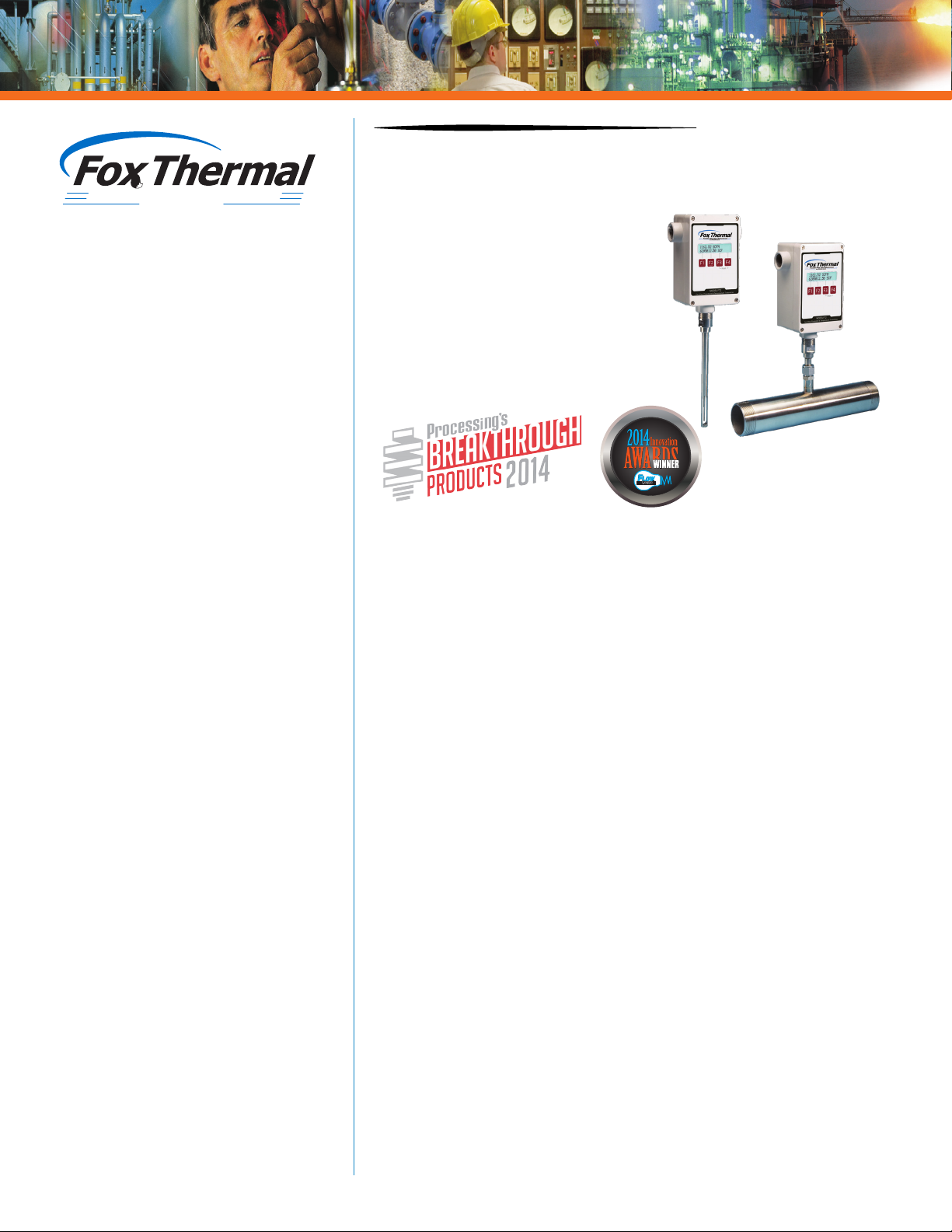
PRESSURE DROP DIMENSIONS
Pressure Drop Charts for Inline Flow Meters
As seen in the charts below, pressure drop is negligible and energy
losses are minimal.
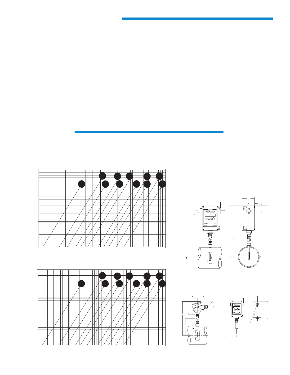
Meter Dimensional Drawings
The FT2A is available in many different
configurations. An example of the
local insertion and remote inline flange
configurations are shown below. To see more
configurations, visit our website at www.
foxthermal.com/literature/
Inches of Water
millibars
Local Insertion
(84)
1.50
(38.0)
1.40
(35)
7.12
(181)
SCFM
2x 3/4 inch NPT Female
FLOW
5.35
(136)
Input
Power
MODEL FT2A
Gas Mass Flowmeter & Temperature Transmitter
C
L
Signal
Wiring
“HH”
“LL”
Remote Insertion
3.3
2X 3/4” NPT,
FEMALE
SHIELDED, 100ft (30.48m) MAX
(84)
1.50
(38)
1.4
(35)
7.12
(181)
4.4
“HH”
(112)
2.0
(51)
4.5
(114)
“LL”
FLOW
CONDUIT,
3/4”, METAL
C
L
5.35
(136)
MODEL FT2A
Gas Mass Flowmeter & Temperature Transmitter
REMOTE CABLE, 5 CONDUCTOR,
NM3/hr
Page 3

SIZING
Dimensions
Assuming there is no insulation or retractor, Fox
recommends the following probe lengths:
Pipe Size Probe Length
1.5" (40mm) to 6" (150mm) 6-inch
8" (200mm) to 12" (300mm) 9-inch
14" (350mm) to 18" (450mm) 12-inch
Use the equation on previous page for larger pipe sizes
Probe Lengths (LL) in inches(cm) =
6.0 (15.2) 9.0 (22.9) 12.0 (30.5)
15.0 (38.1) 18.0 (45.7) 24.0 (61.0)
30.0 (76.2) 36.0 (91.4)
Insertion Flow Meters: Probe diameter: ½”
Equation for selecting insertion ow meter probe length:
Probe length = ½ pipe ID (in inches) + 2” + thickness of
insulation (if any) + dimension of retractor (if supplied).
Round up to the next standard probe length available.
Contact Fox for longer probes.
Inline Flow Meter Dimensions
Pipe size L
0.25" 5.80 (147) 9.9 (251)
0.5" 12.0 (305) 9.9 (251)
0.75" 12.0 (305) 9.9 (251)
1" 12.0 (381) 9.9 (251)
1.25" 12.0 (305) 9.9 (251)
1.5" 12.0 (305) 9.9 (251)
2" 12.0 (305) 9.9 (251)
2.5" 18.0 (457) 10.0 (254)
3" 18.0 (457) 10.0 (254)
4" 18.0 (457) 10.5 (267)
6" 24.0 (610) 11.6 (295)
HH
Note: Dimensions are in inches (mm). For certified drawings,
consult factory or view at www.foxthermal.com/literature/
Approvals
CE: Approved
EMC Directive; 2004/108/EC
Electrical Equipment for Measurement, Control, and Lab
Use: EN61326-1:2008
Low Voltage Directive (LVD): 2006/95/EC
Product Safety Testing: EN 61010-1: 2010
Pressure Equipment Directive: 97/23/EC
Weld Testing: EN ISO 15614-1 and EN ISO 9606-1, ASME
B31.3
FM and FMc: Approved
Class I, II, III, Division 2, Groups A, B, C, D, E, F, G, T4A
hazardous locations.
NEMA 4X Approved
NOTE! The EU Pressure Equipment Directive (PED) requires
that the minimum ambient and uid temperature rating for
carbon steel ow bodies not be below -29C.
Try the Fox thermal online congurator
Precision Mass Flow Measurement
An ON
I
CON Brand
399 RESERVATION ROAD
MARINA, CA 93933
PHONE: 831-384-4300
FAX: 831-337-5786
sales@foxthermal.com
www.foxthermal.com
to request a quote for a meter suited for your
APPROVALS & SPECIFICATIONS
Performance Specs
Flow Accuracy:
Inline meter: ± 1% of reading ± 0.2% of full scale.
Insertion meter: ± 1% of reading ± 0.2% of full scale.
Straight, unobstructed pipe requirement:
Inline: 8 diameters upstream; 4 downstream.
Insertion: 15 diameters upstream; 10 downstream.
Insertion (¼” size): 6” (152mm) upstream &
downstream
Flow Repeatability: ± 0.2% of full scale
Flow Response Time: 0.9 seconds (one time constant)
Temperature Accuracy:
± 1.8° F (± 1.0° C) over -40 to 250° F (-40 to 121° C);
± 3.6° F (± 2.0° C) over 250 to 650° F (121 to 343° C).
Minimum velocity 60 SFPM.
specic process conditions.
www.foxthermal.com
Page 4

SPECIFICATIONS
Operating Specs
Units of Measurement (field-selectable):
SCFM, SCFH, NMPS, NM3/M, NM3/H, NM3/D, NLPS,
NLPM, NLPH, MCFD, MSCFD, SCFD, MMSCFD, MMSCFM,
SMPS, SM3/D, SM3/H, SM3/M, LB/S, LB/M, LB/H, LB/D,
KG/S, KG/M, KG/H, SLPM, SFPM, MT/H
Flow Rates for Insertion Flow Meters:
15 to 60,000 SFPM (0.07 to 280 NMPS) - Air at 70°F
(20°C) & 1 ATM
Turndown: up to 1000:1; 100:1 typical
To determine if an insertion ow meter will operate
properly, divide the maximum ow rate by the pipe area.
The application is acceptable if the velocity is within the
velocity range above.
Typical Flow Ranges for Insertion Flow Meters
Pipe size SCFM MSCFD NM3/hr
1.5" (40mm) 0 - 840 0 - 1,220 0 - 1,325
2" (50mm) 0 - 1,400 0 - 2,020 0 - 2,210
2.5” (63mm) 0 - 2,000 0 - 2,880 0 - 3,150
3" (80mm) 0 - 3,100 0 - 4,440 0 - 4,890
4” (100mm) 0 - 5,300 0 - 7,650 0 - 8,360
6" (150mm) 0 - 12,000 0 - 17,340 0 - 18,930
8" (200mm) 0 - 20,840 0 - 30,020 0 - 32,870
10” (250mm) 0 - 32,800 0 - 47,250 0 - 51,740
12" (300mm) 0 - 46,600 0 - 67,180 0 - 73,500
Flow Ranges for Inline Flow Meters
Size
0.25" 0 - 7.5 0 - 10.8 0 - 11.8
0.5" 0 - 125 0 - 180 0 - 200
0.75" 0 - 220 0 - 320 0 - 350
1" 0 - 360 0 - 520 0 - 570
1.25" 0 - 625 0 - 900 0 - 990
1.5" 0 - 840 0 - 1,220 0 - 1,325
2" 0 - 1,400 0 - 2,020 0 - 2,210
2.5" 0 - 2,000 0 - 2,880 0 - 3,150
3" 0 - 3,100 0 - 4,440 0 - 4,890
4" 0 - 5,300 0 - 7,650 0 -8,360
6" 0 - 12,000 0 - 17,340 0 - 18,930
Note: Standard conditions of air at 70°F and one
atmosphere. Consult factory for other gases and for flow
ranges above and below those listed above.
Gas Pressure (maximum):
Insertion: 500 psig (34.5 barg)
316 SS inline with NPT ends: 500 psig (34.5 barg)
316 SS inline with 150 lb. flanges: 230 psig (16 barg)
CS inline with NPT ends: 300 psig (20.1 barg)
CS inline with 150 lb. flanges: 285 psig (19.7 barg)
Retractor: 125 psig (8.6 barg)
High pressure retractor: NPT 600 psig (41.4 barg), ANSI
150 flange & ANSI 300 flange, no valve supplied.
Notes:
• Check with factory for higher pressure options.
• When teflon ferrule option ordered, gas pressure is
60psig (4.1 barg) maximum.
• Pressure ratings stated for temperature of 100°F
(38°C).
SCFM MSCFD NM3/hr
Relative Humidity: 90% RH maximum; non-condensing
Temperature:
Std sensor: -40 to 250°F (-40 to 121°C)
HT Sensor: -40 to 650°F (-40 to 343°C)
Enclosure: -40 to 158°F (-40 to 70°C) DC Power*
-4 to 158˚F (-20 to 70˚C) AC Power
*Note: Display dims below -4˚F (-20˚C); function returns
once temperature rises again.
Remote sensor junction box ambient temperature: -40 to
212˚F (-40 to 100˚C)
Input Power (without the Anybus serial communication
option):
24VDC
—
(±10%), 0.4 Amps (standard DC Power)
– – –
100 to 240VAC ~(+10%/-15%), 50-60Hz, 0.2 Amps (with
AC power option)
Input Power (with Anybus serial communication option):
24VDC
—
±10%), 0.7 Amps (standard DC Power)
– – –
(
100 to 240VAC~(+10%/-15%), 50-60Hz, 0.2 Amps (with
AC power option)
Note: Fluctuations of AC and DC power supply are not
to exceed ±10% of rating.
Class I Equipment (Electrical Grounding Required for
Safety).
Installation (Over-voltage) Category II for transient overvoltages.
Outputs:
Two isolated 4-20mA outputs (output one is for ow
rate & output two is programmable for ow rate or
temperature); fault indication per NAMUR NE43.
Isolated pulse output 0 to 100Hz, 5 to 24 volts p/p for
ow (the pulse output can be used as an isolated solid
state output for alarms); 20mA max.
Serial Communication:
USB connector for connecting to a laptop or computer
is standard; free PC-based software tool - FT2A View™ provides complete conguration, remote process monitoring and data logging functions.
Optional isolated communication outputs: RS485-
Modbus, BACnet MS/TP, Probus-DP, DeviceNet or
Ethernet Modbus TCP.
4-20mA Loop Verication:
Simulation mode used to align 4-20mA output with the
input to customer’s PLC/DCS.
Physical Specs
Sensor Material:
316 stainless steel standard; Hastelloy C276 optional
Inline Flow Body Material:
316 Stainless Steel ow bodies standard; Optional A106
Grade B carbon steel ow bodies and A105 anges.
Enclosure:
NEMA 4X, aluminum, dual conduit entries with ¾” NPT or
optional M20 x 1.5mm.
Remote Sensor Cable:
5-conductor, 18 AWG, twisted, shielded, 100 feet
maximum.
Retractor Assemblies:
Packing gland assembly: 125 psig (8.6 barg ) max.
High pressure (crank) retractor: NPT 600 psig (41.4 barg),
ANSI 150 ange & ANSI 300 ange, no valve supplied.
FT2A Rev. N
 Loading...