

Page 1

Fox Thermal Instruments, Inc.
THERMAL MASS FLOW METER & TEMPERATURE TRANSMITTER
Model FT2A - Anybus:
Profibus/DeviceNet/Modbus TCP Ethernet
www.foxthermalinstruments.com | 399 Reservation Road Marina, CA. 93933
105436
Rev. A
Page 2

Anybus
Notice
This publication must be read in its entirety before performing any operation. Failure
to understand and follow these instructions could result in serious personal injury
and/or damage to the equipment. Should this equipment require repair or adjustment
beyond the procedures given herein, contact the factory at:
FOX THERMAL INSTRUMENTS, INC.
399 RESERVATION ROAD
MARINA, CA 93933
TELEPHONE: 831-384-4300
FAX: 831-337-5787
EMAIL: SERVICE@FOXTHERMALINSTRUMENTS.COM
Download Technical Data Sheets from our website:
www.foxthermalinstruments.com
Fox Thermal Instruments believes that the information provided herein is accurate
however be advised that the information contained herein is NOT a guarantee
FOX THERMAL INSTRUMENTS
for satisfactory results. Specifically, this information is neither a warranty nor
guarantee, expressed or implied, regarding performance; merchantability; fitness;
or any other matter with respect to the products; nor recommendation for the use
of the product/process information in conflict with any patent. Please note that Fox
Thermal Instruments, Inc. reserves the right to change and/or improve the product
design and specification without notice.
Fox FT2A Manuals:
• Model FT2A Instruction Manual
• Fox FT2A View™ Instruction Manual
• Fox FT2A Modbus and BACnet MS/TP Manual
2
Page 3

Table Of Contents
1. Introduction Page 4
a. Scope Page 4
b. Description Page 4
c. Related Documents Page 4
2. Data Organization Page 5
a. FT2A Registers Page 5
b. Status Bit Definitions Page 6
c. Control Page 6
3. Wiring and Configuration for Profibus/Devicenet/Ethernet Page 7
a. Profibus Page 7
b. DeviceNet Page 9
c. Ethernet Page 11
Anybus
TABLE OF CONTENTS
4. LED Indicators Page 14
5. Programming Page 15
a. Anybus Chip Programming Page 15
6. Appendices Page 16
a. Attachment A Page 16
b. Attachment B Page 19
7. Glossary of Terms and Abbreviations Page 22
8. Index Page 23
3
Page 4

Anybus
Introduction
Scope
Introduction
INTRODUCTION
Scope
Thank you for purchasing the Model FT2A Thermal Gas Mass Flow meter and
Temperature Transmitter from Fox Thermal Instruments. The Model FT2A is
one of the most technically advanced flow meters in the world. Extensive
engineering effort has been invested to deliver advanced features, accurate
measurement performance and outstanding reliability.
This document describes how to connect and use the Profibus/DeviceNet/
Modbus TCP Ethernet for the Model FT2A.
Description
The Model FT2A uses a pre-programmed Anybus-IC from HMS-Network to
interface to Profibus, DeviceNet or Modbus TCP Ethernet.
Related Documents
Documentation for the Anybus-IC is available on the HMS-Networks Website
at www.anybus.com/support. Select Anybus-IC to go to the support
documentation. Design guides are available under any single chip selection.
The following documents can be downloaded from the Anybus Website:
• Single chip for Profibus, Design Appendix
• Single chip for DeviceNet, Design Appendix
• Single chip for Ethernet/IP and Modbus TCP, Design Appendix
Other related documents:
• Fox FT2A Instruction Manual
• Fox FT2A View™ Manual
• Fox FT2A Modbus/BACnet MS/TP Manual
www.foxthermalinstruments.com
4
Page 5

Data Organization
Anybus
Data Organization
Byte Modbus
Address
00
30001
01
02
30002
03
04
30003
05
06
30004
07
08
30005
09
10
30006
11
12
30007
13
14
30008
15
16
30009
17
18
30010
19
202130011 Status (low register, MSB)
222330012 Flow *100 (low register, MSB)
242530013 Total *100 (low register, MSB)
Data Organization
Data from the FT2A is updated into the Anybus IC every 300 ms. Data is
organized as a set of two 16 bit registers (32 bits) for data and one 16 bit
register for status. Table 2.1 defines the FT2A registers.
Table 2.1: FT2A Registers
Data Type Scaling Comment
Flow in Eng units (low register, MSB)
Flow in Eng units (low register, LSB)
Flow in Eng units (high register, MSB)
Flow in Eng units (high register, LSB)
Total (low register, MSB)
Total (low register, LSB)
Total (high register, MSB)
Total (high register, LSB)
Temperature (low register, MSB)
Temperature (low register, LSB)
Temperature (high register, MSB)
Temperature (high register, LSB)
Elapsed time (low register, MSB)
Elapsed time (low register, LSB)
Elapsed time (high register, MSB)
Elapsed time (high register, LSB)
Velocity (low register, MSB)
Velocity (low register, LSB)
Velocity (high register, MSB)
Velocity (high register, LSB)
Status (low register, LSB)
Flow *100 (low register, LSB)
Total *100 (low register, LSB)
No Mass flow in selected units
No Total in selected units
X 10 Temperature in selected units X 10 (Times
ten)
High register in not used
X 10 Elapsed time in hours X 10 (Times ten)
No Velocity in nm/hr
No Status/Alarm
X 100 Flow X 100
X 100 Total X 100
DATA ORGANIZATION
i
Note: Items 22/23 and 24/25 are only used for low flow and total to obtain more precision.
Velocity can be used to obtain flow rate in engineering units using pipe area and unit
conversion factor.
5
Page 6

Anybus
Data Organization
Status Bits
Table 2.2: Status Bits Definitions
Bit Definition Comment
0 Power up indication
1 Flow rate reached high limit threshold
2 Flow rate reached low limit threshold
3 Temperature reached high limit threshold
4 Temperature reached low limit threshold
5 Sensor reading is out of range
6 Velocity flow rate outside of calibration table
7 Incorrect Settings
8 In simulation mode
9 Frequency output is out of range
10 Analog 4-20 mA for flow is out of range
11 Analog 4-20 mA for temperature is out of range
12 Anybus error
13 Bridge Shut Down
DATA ORGANIZATION
14 EEPROM CRC error
15 Totalizer Error Detected
Reset when out of the power up sequence
Set limit to zero to disable
Set limit to zero to disable
Set limit to zero to disable
Set limit to zero to disable
Check sensor wiring
Check sensor wiring
Check settings
Set simulation value to 0 to disable
Check frequency output settings
Check analog output settings
Check analog output settings
Check wiring from RS485 to Anybus IC
Check sensor wiring
Check parameters and reset CRC
Reset the total
Control
One control register is used to reset the total and elapsed time. Data for that
register must be set to 0x02 to reset the total. Only a transition from a 0 to
2 will clear the total. Keeping that bit set will not continuously clear the total.
This register needs to be cleared after the reset operation.
6
Page 7
ETHERNET
RESET TOTAL
SWITCH
USB
COMMUNICATION
J1
S5
J4
Wiring: Profibus
Anybus
Probus Wiring
Profibus Wiring from Master
Wiring connections are made to terminal block TS3 for Profibus
communication. The following lists the wiring connections.
Display board Connector TS3:
FB1 A-Line
•
• FB2 B-Line
• FB3 RTS
• FB4 NC (NC = No Connection)
• FB5 GND BUS
• FB6 +5 V BUS
• FBPE PE
• SHIELD NC
Fig. 3.1: Profibus Wiring and Configuration
Inside Display/Cover
Profibus Master
PROFIBUS
TS3
1
2
3
4
5
6
7
8
OPTIONAL
COMMUNICATION
(DEVICENET
PROFIBUS)
FB1 - A-Line
FB2 - B-Line
FB3 - RTS
FB4 - No Connection
FB5 - GND Bus
FB6 - +5 V Bus
FBPE - PE
SHLD - SHLD
7
Page 8

Anybus
Configuration: Profibus
Model FT2A
Probus
Conguration
PROFIBUS
Baud Rate - Profibus
The Module supports all standard baud-rates from 9600 bps to 12 Mbps,
according to the Profibus specification. The Anybus-IC PDP supports
automatic baud rate detection, which means that the actual baud rate is only
configured in the Profibus Master.
Configuration File - Profibus
A GSD configuration file is needed by the master and is available from the
HMS-Networks Website under the AnyBus-IC/Profibus selection.
An example of the file is included for reference as Attachment A.
http://www.anybus.com/support/support.
asp?PID=88&ProductType=AnyBus-IC
Profibus Functions
The following functions are not supported with the Standard GSD-file:
User Parameter Data (Set_Prm).
Extended Diagnostic Data (Slave_Diag).
ID Number - Profibus
The Standard AnyBus-IC Profibus ID number is 1810h. This ID number is
related to the GSD file. If the AnyBus IC PDP is to be customized with other
functions or names, a new ID-number must be used (ordered from the
Profibus organization).
8
Page 9

ETHERNET
RESET TOTAL
SWITCH
USB
COMMUNICATION
J1S5J4
Wiring: DeviceNet
Anybus
DeviceNet Wiring
DeviceNet Wiring from Master
Wiring connections are made to terminal block TS3 for DeviceNet
communication. The following lists the wiring connections.
Display board Connector TS3:
• FB1 CAN_H
• FB2 CAN_L
• FB3 NC
• FB4 NC
• FB5 V- (GND)
• FB6 V+ (24 Volt DC)
• FBPE PE
• SHIELD SHIELD
CAN-H and CAN-L Termination Resistor
Connect a termination resistor across the receive/transmit signals of the
last device on the DeviceNet communication line. To connect the 120 ohm
termination resistor on the FT2A, set jumper W4 to the TERM position.
The termination resistor of the FT2A is disconnected by setting jumper W4 to
the NC (Not Connected) position.
DEVICENET
Fig. 3.2: DeviceNet Wiring from Master
Inside Display/Cover
W4
TERM NC
TS3
1
2
3
4
5
6
7
8
OPTIONAL
COMMUNICATION
(DEVICENET
PROFIBUS)
DeviceNet Master
FB1 - CAN_H
FB2 - CAN_L
FB3 - No Connection
FB4 - No Connection
FB5 - V -
FB6 - V+
FBPE - PE
SHLD - SHIELD
9
Page 10

Anybus
Configuration: DeviceNet
DeviceNet
Conguration
DEVICENET
Baud Rate - DeviceNet
Automatic baud rate detection is not supported. The baud rates that are
supported by the Anybus-IC DeviceNet are:
125 kbps
250 kbps
500 kbps
Configuration File - DeviceNet
Electronic Data Sheet (.EDS)
An EDS configuration file used by the master, it can be downloaded from the
HMS-Networks Website under the Anybus-IC and DeviceNet selection.
An example of the file is included for reference as Attachment B.
http://www.anybus.com/support/support.
asp?PID=88&ProductType=Anybus-IC or a quick Google search for AnybusIC.
10
Page 11

Inside Display/Cover
OPTIONAL
COMMUNICATION
(DEVICENET
PROFIBUS)
RESET TOTAL
SWITCH
USB
COMMUNICATION
1
2
3
4
5
6
7
8
TS3
S5
J4
W4
TERM
NC
Wiring: Ethernet
Anybus
Ethernet Wiring
Ethernet Wiring
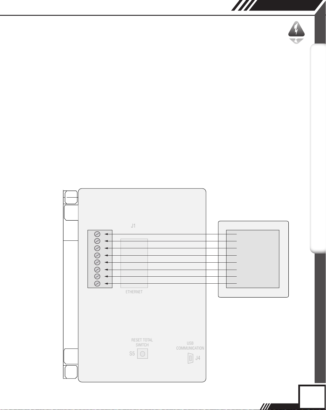
Connection to the network is accomplished by simply connecting to the
Ethernet connector mounted on the local display board (J1). If you are
connecting directly to a PC, you will need a crossover Ethernet cable.
Fig. 3.3: Ethernet Connector Location
ETHERNET
J1
ETHERNET
11
Page 12

Anybus
Configuration: Ethernet
Ethernet
Conguration
ETHERNET
Manual IP Address Configuration
Set the rotary switch setting to any desired position except zero. The IP
address will be set to 192.168.0.x, where x is the setting on the 2 digits of the
rotary switches.
Automatic IP Address Configuration
Set the rotary switches to zero. The Anybus chip has been programmed for
DHCP.
The control register for Ethernet is at address zero.
The Anybus-IC offers many other ways to operate. See the Anybus-IC Design
Guide. Programming of the Anybus-IC can be accomplished by connecting
a PC with a terminal emulator to the P2 connector on the local display with a
special Fox adapter board. The Anybus document can be downloaded from the
web at the following link :
http://www.anybus.com/support/support.asp?PID=88&ProductType=Anybus-IC or a
quick Google search for Anybus-IC.
Configuring the FT2A Ethernet IP with a Fixed Address
Set rotary IP address switches located on the local display board to an address
(i.e. 2, sw1=2, sw2=0)
Cycle the power and connect a cross-over Ethernet cable to a PC.
12
Note: Some PC/laptops can use a straight cable as they detect and switch the
lines automatically.
i
Open the web browser and enter 192.168.0.2 for the address and press enter.
The HMS Configurator should now be displayed. If not, check the cable and the
switch settings. (Addresses other than 2 may be used).
• Enter the IP address, Subnet mask and the gateway address in the HMS
Configurator.
• Uncheck “DHCP Enable” box.
• Click on “Save Configuration”.
• Reset the rotary IP switch address to 0 (sw1=0, sw2=0).
• Cycle the power and connect a straight Ethernet cable to the network.
• Ping the device with the IP address entered to verify the communication
link.
Page 13

Configuration: Ethernet
Anybus
Ethernet
Conguration
Protecting Access to FT2A HMS Configurator for Ethernet IP
Access to the HMS Configurator can be protected by creating a file containing
user names and passwords and storing it in the FT2A Anybus root directory as
specified in section 6-2 of the HMS Anybus Ethernet manual (see note below
for manual downloads). The file can be created using Notepad or any other
text editor.
For example:
User1:1234
User2:5678
Using Windows Explorer or any FTP program, transfer the file that you just
created into the FT2A Anybus root directory (See section 4-2 of the HMS
Ethernet manual). First connect to the FT2A by opening Windows Explorer and
replace the address with “FTP://xxx.xxx.xxx.xxx (where x is the IP address) and
press return. Windows explorer should now show the content of the specified
FT2A Anybus directory. Highlight the file that was created and drag it into the
folder that has the IP address.
Slave Address
The Slave Address is set using the two BCD rotary switches. Address can be
set from 0 to 99, for the Profibus/Modbus TCP Ethernet and from 0 to 63 for
the DeviceNet. Power needs to be cycled before the settings take effect. Rotary
switch SW1 controls the low digit address, SW2 the high digit address (ie
SW1=5, SW2=6, Address=65).
ETHERNET
i
Note: Links to HMS Manual Downloads
http://www.anybus.com/products/abic.shtml
Ethernet:
http://www.hms.se/upload/90-9118-ABIC-EIP_1_56_ROHS_SCM_1200_055.pdf
Ethernet
Profibus:
http://www.hms.se/upload/88-2310-Anybus-IC_PROFIBUS_2_00_SCM-1200-
022.pdf
DeviceNet:
http://www.hms.se/upload/89-7638-Anybus-IC_DeviceNet_user_manual.pdf
13
Page 14

J1
U2
J3
TS3
SW1
SW2
S6
Anybus
LED Indicators
LED Indicators
LED INDICATORS
LED’s
The local display board with the Anybus-IC option provides 3 LED’s with the
following functionality:
• LP1, Green LED: Flashes at 1 Hz indicating normal local display
operation
• LP2, Green LED: Showing green when Fieldbus communication/
connection is working properly
• LP3, Red LED: Showing red when Fieldbus communication/connection
is not working properly.
Fig. 4.1: LED Locations
LP2LP3
LP1
14
Page 15

Programming
Anybus
Anybus Chip
Programming
i
Anybus Chip Programming
The Anybus chip (U2) is shipped pre-programmed. If an AnyBus-IC PDP is
used in a customer-specific implementation, the Profibus ID-number and the
GSD-file must be changed to match the new implementation. This can be
accomplished using a terminal emulator (like "Hyperterminal") through a serial
or USB interface to connector P2 (see Fig. 5.1). A special cable is available
from FOX. HyperTerminal communication parameters should be set to 9600
Baud, 8 Bits, 1 Stop bit. Refer to the Anybus documentation for programming.
Note: After changing parameters for the Anybus Chip from the local display
(i.e baudrate, bus type) the FT2A needs to have the power cycled OFF and
back ON twice before the changes can take effect.
Fig. 5.1: Anybus Circuitry
PROGRAMMING
15
Page 16

Anybus
Appendices
Attachment A
APPENDICES
Attachment A
AnyBus_Profibus.gsd
;===================================
=========================
; Profibus Device Database of HMS Industrial Networks AB
; Model : ANYBUS-IC PDP
; Description : ANYBUS-IC Profibus DP slave
; Language : English
; Date : 30 September 2003
; Author : HMS Industrial Networks AB
;
; MODIFICATIONS:
; 30 September 2003:
; - 'MaxTsdr_xxx' for all baudrates have been optimized for the SPC3 ASIC.
; - 'Revision' upgrade
; - 'Hardware_Release' upgrade
; - 'Software_Release' upgrade
;===================================
=========================
#Profibus_DP
16
GSD_Revision = 2
; Device identification
Vendor_Name = "HMS Industrial Networks AB"
Model_Name = "AnyBus-IC PDP"
Revision = "Version 1.1"
Ident_Number = 0x1810
Protocol_Ident = 0 ; DP protocol
Station_Type = 0 ; Slave device
FMS_supp = 0 ; FMS not supported
Hardware_Release = "Version 1.1"
Software_Release = "Version 1.1"
;Used bitmap
Bitmap_Device = "ABIC_DE"
Bitmap_Diag = "ABIC_DI"
Bitmap_SF = "ABIC_SF"
Page 17

Appendices
Anybus
Attachment A
; Supported baudrates
9.6_supp = 1
19.2_supp = 1
45.45_supp = 1
93.75_supp = 1
187.5_supp = 1
500_supp = 1
1.5M_supp = 1
3M_supp = 1
6M_supp = 1
12M_supp = 1
; Maximum responder time for supported baudratesMaxTsdr_9.6 = 15
MaxTsdr_19.2 = 15
MaxTsdr_45.45 = 15
MaxTsdr_93.75 = 15
MaxTsdr_187.5 = 15
MaxTsdr_500 = 15
MaxTsdr_1.5M = 25
MaxTsdr_3M = 50
MaxTsdr_6M = 100
MaxTsdr_12M = 200
APPENDICES
; Supported hardware features
Redundancy = 0 ; not supported
Repeater_Ctrl_Sig = 2 ; TTL
24V_Pins = 0 ; not connected
Implementation_Type = "SPC3"
; Supported DP features
Freeze_Mode_supp = 1 ; supported
Sync_Mode_supp = 1 ; supported
Auto_Baud_supp = 1 ; supported
Set_Slave_Add_supp = 1 ; supported
; Maximum polling frequency
Min_Slave_Intervall = 1 ; 100 us
; Maximum supported sizes
Modular_Station = 1 ; modular
17
Page 18

Anybus
Appendices
Attachment A
APPENDICES
Max_Module = 24
Max_Input_Len = 48
Max_Output_Len = 48
Max_Data_Len = 96
Modul_Offset = 1
Fail_Safe = 1 ; Data telegram without data in state
CLEAR accepted
Slave_Family = 0
Max_Diag_Data_Len = 6
; Definition of modules
Module = "IN/OUT: 1 Byte" 0x30
EndModule
;
Module = "IN/OUT: 2 Byte ( 1 word)" 0x70
EndModule
;
Module = "IN/OUT: 4 Byte ( 2 word)" 0x71
EndModule
;
Module = "IN/OUT: 8 Byte ( 4 word)" 0x73
EndModule
;
Module = "IN/OUT: 16 Byte ( 8 word)" 0x77
EndModule
;
Module = "IN/OUT: 32 Byte (16 word)" 0x7F
EndModule
;
Module = "INPUT: 1 Byte" 0x10
EndModule
;
Module = "INPUT: 2 Byte ( 1 word)" 0x50
EndModule
;
Module = "INPUT: 4 Byte ( 2 word)" 0x51
EndModule
;
18
Page 19

Appendices
Anybus
Attachment A
Module = "INPUT: 8 Byte ( 4 word)" 0x53
EndModule
;
Module = "INPUT: 16 Byte ( 8 word)" 0x57
EndModule
;
Module = "INPUT: 32 Byte (16 word)" 0x5F
EndModule
;
Module = "OUTPUT: 1 Byte" 0x20
EndModule
;
Module = "OUTPUT: 2 Byte ( 1 word)" 0x60
EndModule
;
Module = "OUTPUT: 4 Byte ( 2 word)" 0x61
EndModule
;
Module = "OUTPUT: 8 Byte ( 4 word)" 0x63
EndModule
;
Module = "OUTPUT: 16 Byte ( 8 word)" 0x67
EndModule
;
Module = "OUTPUT: 32 Byte (16 word)" 0x6F
EndModule
APPENDICES
Attachment B
Attachment B
89-0754-EDS_ABIC_DEV_3_1.EDS
[File]
DescText = "HMS Anybus-IC DEV";
CreateDate = 11-22-2001;
CreateTime = 07:23:00;
ModDate = 03-14-2007;
ModTime = 14:30:00;
Revision = 3.1;
[Device]
VendCode = 90;
19
Page 20

Anybus
Appendices
Attachment B
APPENDICES
VendName = "HMS Networks";
ProdType = 12;
ProdTypeStr = "Communications Adapter";
ProdCode = 61;
MajRev = 3;
MinRev = 1;
ProdName = "Anybus-IC DeviceNet";
Catalog = "Anybus-IC DeviceNet";
DNetQC =
0x0001, $ Quick Connect supported at Powerup
265; $ 265 ms Powerup time
[IO_Info]
Default = 0x0001; $ Default IO Connection = Poll
PollInfo =
0x000F, $ Compatible IO type mask = All connections
1, $ Input1
1; $ Output1
StrobeInfo =
COSInfo =
CyclicInfo =
Input1 =
0x000F, $ Compatible IO type mask = All connections
1, $ Input1
1; $ Output1
0x0007, $ Compatible IO type mask = All connections
1, $ Input1
1; $ Output1
0x000B, $ Compatible IO type mask = All connections
1, $ Input1
1; $ Output1
1, $ 1 byte
0, $ All bits are significant
0x000F, $ Compatible IO type mask = All connections
20
Page 21

Appendices
Anybus
Attachment B
"ABIC Produce", $ Name
6, $ Path size
"20 04 24 64 30 03", $ Assembly object, Inst 100, Attr 3
"Data produced by the Anybus-IC";
Output1 =
1, $ 1 byte
0, $ All bits are significant
0x000F, $ Compatible IO type mask = All connections
"ABIC Consume", $ Name
6, $ Path size
"20 04 24 96 30 03", $ Assembly object, Inst 150, Attr 3
"Data consumed by the Anybus-IC ";
[ParamClass]
MaxInst = 0; $ Max Instances - total # configuration parameters
Descriptor = 0x0000; $ Parameter Class Descriptor - No parameters
CfgAssembly = 0; $ The config assembly is not supported.
APPENDICES
21
Page 22

Anybus
Definitions
Glossary of Terms
and Denitions
Aa
DEFINITIONS
EDS Electronic Data Sheet
IP Internet Protocol
PC Personal Computer
TERM Termination Resistor
22
Page 23

Index
Index
Anybus Chip Location, p. 15
Attachment A, p. 16
Attachment B, p. 19
CAN-H and CAN-L Termination Resistor, p. 9
Configuring Ethernet IP (Fixed Address), p. 12
Configuration
DeviceNet, p. 10
Ethernet, p. 12
Profibus, p. 8
Data Organization, p. 5
FT2A Registers, p. 5
Status Bits Definitions, p. 6
Control, p. 6
DeviceNet Baud Rate, p. 10
DeviceNet Configuration File, p. 10
Ethernet Automatic IP Address Configuration, p. 12
Ethernet Manual IP Address Configuration, p. 12
Introduction, p. 4
Scope, p. 4
LED Indicators, p. 14
Profibus Baud Rate, p. 8
Profibus Configuration File, p. 8
Profibus Functions, p. 8
Profibus ID File, p. 8
Programming, p. 15
Anybus, p. 15
Protecting Access (Ethernet), p. 13
Scope, p. 4
Slave Address, p. 13
Wiring
DeviceNet, p. 9
Ethernet, p. 11
Profibus, p. 7
Anybus
INDEX
23
Page 24

i
Information
Caution
Wiring
Aa
Definition of Terms
Troubleshooting Tips
 Loading...