

Page 1
sales@foxthermalinstruments.com
Company Name and Address: Customer P.O. Number:
Tag Number: (20 characters maximum)
For Fox Office Use:
Phone:
Contact:
Email Address:
Describe type of application (e.g. boiler feed, flare gas, etc.). F1 F2 F3 F4
F5 F6 F7 F8
N/A for Remote
Gas Name: 4 mA Value 20 mA Value
Output Units:
SCFM NLPS SMPS KG/S
SCFH NLPM SM3/M KG/M
SCFD NLPH SM3/H KG/H
NMPS MSCFD SM3/D SLPM
Minimum Nominal Maximum Units NM3/M MMSCFD LB/S SFPM
NM3/H MMSCFM LB/M MT/H
Flow Rate: NM3/D MCFD LB/H LB/D
Temperature: (Normally Zero)
Pressure:
Standard: 60°F and 14.73 psia (AGA standard for natural gas)
70°F and 14.73 psia
0°C and 760mm Hg
N/A for lbs or kg units
Other (indicate units):
and
Pipe size Schedule Pipe ID*
For Fox Office Use:
Velocity: SFPM
Rep/Distributor: Contact:
Factory Use Only: Tunnel Cal. Gas Hours psig Cal. Pres.
Model #:
Flow meter and Display Orientation - See Code Sheet
Flow Rate 4 to 20 mA Scaling and Display Units Selection
Temperature Setup
Temperature Units: F or C
Application Description
Please attach a gas composition analysis.
Fox Thermal Instruments, Inc.
399 Reservation Road, Marina, CA 93933
Phone: (831) 384-4300 Fax: (831) 384-4312
CUSTOMER INFORMATION
Application Data Sheet
Model FT2A Flow Meters
2/18/2014
Standard Temperature and Pressure (STP)
straight pipe diameters downstream of the flow meter.
Insertion Flow meters: Fox recommends 15 pipe diameters of straight pipe upstream of the flow meter and 10 diameters downstream.
Inline Flow meters: Fox recommends 8 pipe diameters of straight pipe upstream of the flow meter and 4 diameters downstream.
If you do not have the recommended straight pipe please enter upstream and downstream information for your application:
* Accurate pipe/duct inside diameter required for Insertion Flow Meter applications to ensure correct flow rate calculation.
INSTRUMENT DETAILS
PROCESS DETAILS
Process Conditions
Mixed Gas Information
Gas Information
Total composition must add up to 100%.
S.O. #:
Serial #:
Indicate if data is % Volume (moles) or % Weight (mass).
20 mA Value:
4 mA Value:
straight pipe diameters upstream of the flow meter.
PIPING INFORMATION AND STRAIGHT PIPE REQUIREMENTS
Duct Dimensions*
Non Resettable Totalizer
Configure as Non Resettable Totalizer.
F-143, FT2A Application Data Sheet (PDF) Rev. B, 02/18/14
Page 2
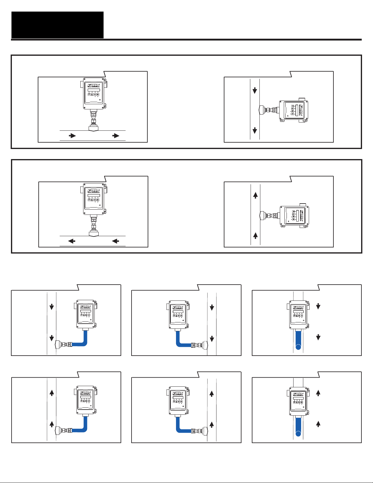
Fox Thermal Instruments FT2A Display Configuration Codes
FLOW
Reset
Gas Mass Flowmeter & Temperature Transmitter
MODEL FT2A
FM/FMc
FLOW
Reset
Gas Mass Flowmeter & Temperature Transmitter
MODEL FT2A
FM/FMc
FLOW
Reset
Gas Mass Flowmeter & Temperature Transmitter
MODEL FT2A
FM/FMc
FLOW
Reset
Gas Mass Flowmeter & Temperature Transmitter
MODEL FT2A
FM/FMc
FLOW
Reset
Gas Mass Flowmeter & Temperature Transmitter
MODEL FT2A
FM/FMc
FLOW
Reset
Gas Mass Flowmeter & Temperature Transmitter
MODEL FT2A
FM/FMc
FLOW
Reset
Gas Mass Flowmeter & Temperature Transmitter
MODEL FT2A
FM/FMc
FLOW
Reset
Gas Mass Flowmeter & Temperature Transmitter
MODEL FT2A
FM/FMc
FLOW
Reset
Gas Mass Flowmeter & Temperature Transmitter
MODEL FT2A
FM/FMc
FLOW DIRECTION - NO ELBOW KIT
(F1) Flow - Le to Right
OR
FLOW DIRECTION - NO ELBOW KIT
(F2) Flow - Right to Le (F2) Flow Up
OR
(F1) Flow Down
VERTICAL FLOW DIRECTION AND FLOWMETER POSITION
** Elbow Kit required (P/N 102299) - EXTRA CHARGE OPTION **
(F3) Flow Down - Meter Right (F4) Flow Down - Meter Le
(F6) Flow Up - Meter Right
FLOW
FM/FMc
Gas Mass Flowmeter & Temperature Transmitter
Reset
MODEL FT2A
(F7) Flow Up - Meter Le
(F5) Flow Down - Meter Front
(F8) Flow Up - Meter Front
Rev. A, 10/02/13F-142, FT2A Display Conguration Codes
 Loading...