

Page 1

MODEL FT2
THERMAL MASS FLOWMETER & TEMPERATURE TRANSMITTER
399 RESERVATION ROAD
MARINA, CA 93933
101364 Revision L
Page 2

Revision L ECO0762 08/17/11
Notice
This publication must be read in its entirety before performing any operation.
Failure to understand and follow these instructions could result in serious
personal injury and/or damage to the equipment. Should this equipment
require repair or adjustment beyond the procedures given herein, contact the
factory at:
FOX THERMAL INSTRUMENTS, INC.
399 RESERVATION ROAD
MARINA, CA 93933
TELEPHONE: 831-384-4300
FAX: 831-384-4312
EMAIL: SALES@FOXTHERMALINSTRUMENTS.COM
Download Technical Data Sheets from our website:
www.foxthermalinstruments.com
Fox Thermal Instruments believes that the information provided herein is
accurate however be advised that the information contained herein is NOT a
guarantee for satisfactory results. Specifically, this information is neither a
warranty nor guarantee, expressed or implied, regarding performance;
merchantability; fitness; or any other matter with respect to the products; nor
recommendation for the use of the product/process information in conflict
with any patent. Please note that Fox Thermal Instruments, Inc. reserves the
right to change and/or improve the product design and specification without
notice.
101364 Revision L
Page 3

TABLE OF CONTENTS
1. Introduction ..................................................................................................... 1
1.1. Scope ............................................................................................................................................................. 1
1.2. Product Description ....................................................................................................................................... 1
1.3. Block Diagram ................................ ................................ ................................................................ ............... 2
1.3.1. Menu Tree .............................................................................................................................................. 3
1.4. Analog 4-20 mA outputs................................................................................................................................ 5
1.5. Discrete I/O .................................................................................................................................................... 5
1.6. Frequency/Alarm Output ............................................................................................................................... 5
1.7. Local Display Options ................................................................................................................................... 5
1.8. Communication Features ............................................................................................................................... 5
1.9. Dimension Details ......................................................................................................................................... 5
2. Installation......................................................................................................10
2.1. Scope ........................................................................................................................................................... 10
2.2. Insertion Style .............................................................................................................................................. 10
2.2.1. Mounting – Insertion Style .................................................................................................................. 10
2.2.2. Installation Depth ................................................................................................................................. 11
2.2.3. Sensor Orientation ............................................................................................................................... 11
2.2.4. Flowmeter Placement - Insertion Style ................................ ................................................................ 13
2.2.5. Flowmeter Placement - Flow Body Style ............................................................................................ 14
2.2.6. Flow Body Orientation ........................................................................................................................ 15
3. Start Up ..........................................................................................................16
3.1. Scope ........................................................................................................................................................... 16
3.2. Wiring .......................................................................................................................................................... 16
3.2.1. Power Input Wiring and Grounding .................................................................................................... 17
3.2.2. 4 to 20 mA Output Wiring ................................................................................................ ................... 18
3.2.3. Frequency/Alarm Output Wiring ......................................................................................................... 19
3.2.4. RS485 Wiring ...................................................................................................................................... 20
3.2.5. Remote Switch Wiring ......................................................................................................................... 21
3.2.6. Local Sensor Wiring (4 wires) ............................................................................................................. 22
3.2.7. Local Sensor Wiring High Temperature (5 Wire) ............................................................................... 23
3.2.8. Remote Sensor Wiring Installation ...................................................................................................... 24
3.3. Start Up Sequence ........................................................................................................................................ 25
3.4. Measurement Mode ..................................................................................................................................... 25
3.5. 4 to 20 mA Outputs ...................................................................................................................................... 25
3.6. Frequency/Alarm Output ............................................................................................................................. 25
3.7. Local Display Screens ................................................................................................................................. 26
3.7.1. Display Screens ................................................................................................................................... 26
3.7.2. Engineering Screens ............................................................................................................................ 27
3.8. Resetting Total and Elapsed Time ............................................................................................................... 28
3.9. Alarm Indications ........................................................................................................................................ 28
4. Programming .................................................................................................29
4.1. Programming using the Local Display ........................................................................................................ 29
4.1.1. Data Entry using the local display module .......................................................................................... 29
4.1.2. Entering the Programming Mode ......................................................................................................... 30
4.1.3. Analog 4-20 mA Output ...................................................................................................................... 30
4.1.4. Frequency Output ................................................................................................................................ 31
4.1.5. Discrete Input/Output .......................................................................................................................... 33
4.1.6. RS485 Serial Communication Settings ................................................................................................ 34
4.1.7. Display Setup ....................................................................................................................................... 36
4.1.8. Password .............................................................................................................................................. 37
4.1.9. Units Settings ....................................................................................................................................... 38
4.1.10. Flow Parameters .................................................................................................................................. 40
4.1.11. Calibration Parameters ................................................................................................ ......................... 43
Fox Thermal Instruments Inc., 399 Reservation Road, Marina, CA 93933 Page i
Page 4

TABLE OF CONTENTS … CONTINUED
4.1.12. Reset Total and Elapsed Time ............................................................................................................. 44
4.1.13. Restore Database ................................................................................................................................. 44
4.1.14. Reset CRC ........................................................................................................................................... 45
4.1.15. Simulation ............................................................................................................................................ 46
5. Preventative Maintenance ............................................................................48
5.1. Access to Electronics ................................................................................................................................... 48
5.2. Sensor Cleaning ........................................................................................................................................... 48
5.3. Broken or Damaged Probe ........................................................................................................................... 48
5.4. Calibration ................................................................................................................................................... 48
5.5. Fuse Replacement (Standard and NFP version) .......................................................................................... 48
6. Troubleshooting .............................................................................................49
6.1. Replacements Parts ...................................................................................................................................... 50
6.2. Return Procedure ......................................................................................................................................... 51
Warranty .................................................................................................................52
Glossary of Terms and Abbreviations .................................................................53
Index ........................................................................................................................54
Page ii Fox Thermal Instruments, Inc., 399 Reservation Road, Marina, CA 93933
Page 5

101364 Model FT2
1. Introduction
1.1. Scope
This Instruction Manual describes the electrical and mechanical considerations involved with installing
and maintaining the hardware associated with the Fox FT2 Thermal Mass Flowmeter and Temperature
Transmitter.
This manual is divided into the following sections:
Introduction:
Installation:
Start up:
Programming:
Preventive maintenance:
Troubleshooting:
1.2. Product Description
Theory of Operation
The Model FT2 is an advanced thermal mass flowmeter with temperature transmitter. It is
microprocessor-based and field programmable. The FT2 thermal sensor operates on the law that fluids
absorb heat. Therefore, a heated sensor placed in an air or gas stream transfers heat in proportion to
the stream’s mass velocity. There are two sensors in different legs of a balanced bridge circuit, one
sensor detects the fluid’s temperature and a second sensor is maintained at a constant temperature
(constant T) above the fluid’s temperature. The energy applied to the heated sensor to keep this
constant temperature difference is directly proportional to the mass of the flow velocity. The bridge
circuit maintains accurate flow measurement over a large temperature and pressure range.
Mass Flow
The Model FT2 measures mass flow, an advantage over most flowmeters, which measure volumetric
flow rate. Volumetric flow is incomplete because temperature and pressure are unknown and must be
measured separately. For example, the volume of a gas depends on its temperature and pressure. As
temperature and pressure changes, the gas volume changes but not it’s mass. Therefore a device
measuring mass flow is independent of temperature and pressure. By defining a Standard at 70° F and
1 Atmosphere (14.7 psia), 1 Standard cubic foot of gas equals the mass that is in 1 cubic foot of this
gas at 70° F and 1 Atmosphere.
The Model FT2 provides a direct measurement of Standard or Mass units with no additional
temperature and pressure measurements required.
I/O Description
The FT2 comes with two industry standard 4-20 mA isolated analog outputs, one isolated digital
output that can be used for frequency or alarm output, one programmable discrete input and a RS232
communication channel that can interface to a Palm™ handheld or a PC. The two 4 -20 mA outputs
are scalable for the 4 and 20 mA values and are assigned to flow rate and temperature. The frequency
output is programmable to represent flow rate and can be programmed using span/maximum
frequency, unit per pulse or pulse per units. The maximum frequency is 100 Hz. An optional Modbus
protocol is available in a configurable full or half duplex RS485 interface. In addition, a local display
Fox Thermal Instruments Inc., 399 Reservation Road, Marina, CA 93933 Page 1
Page 6
Model FT2 101364
and keypad for field programming the flowmeter and a serial communication channel for Profibus,
DeviceNet or Ethernet are also available as options.
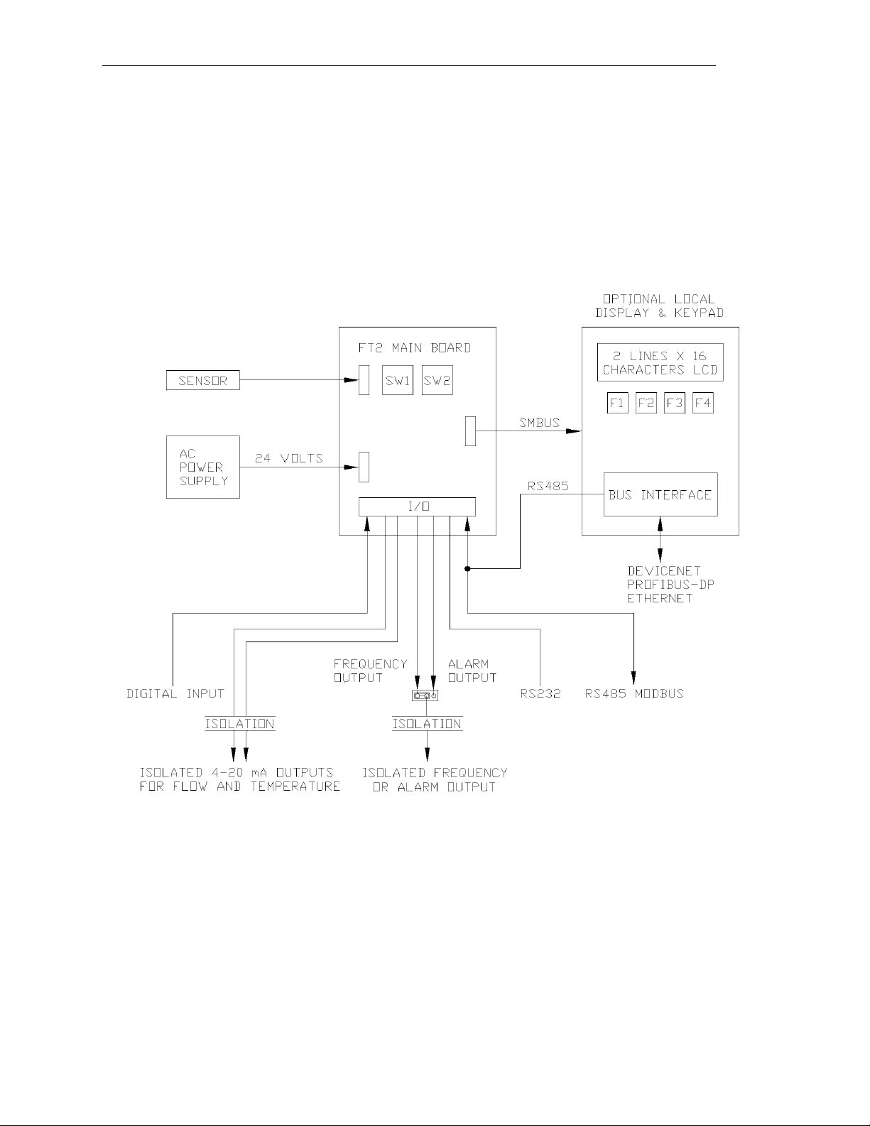
1.3. Block Diagram
The main parts of the FT2 Mass Flowmeter are: The FT2 main board, the sensor assembly, an
optional front panel, and an optional power supply. The two PCBs are mounted inside of the enclosure
and the sensor assembly is mounted external to the enclosure. The optional power supply is mounted
under the main PCB.
Figure 1-1 Block Diagram
Page 2 Fox Thermal Instruments, Inc., 399 Reservation Road, Marina, CA 93933
Page 7
101364 Model FT2
PASWD=
UP DN NXT OK
SET PARAMETERS
I/O FLO DSP EXIT
SET I/O
I/O FEQ 420 EXIT
SET I/O
COM CTC EXIT
Bus = Modbus
NXT OK
Baud = 9600
NXT OK
Parity = EVEN
NXT OK
Data Bits = 8
NXT OK
Stop Bits = 1
NXT OK
LoopID = 1
CHG OK
CONTACT
INP ALM EXIT
Inp = Not Used
NXT OK
ALM = HiFloAlm
NXT OK
FREQUENCY OUTPUT
P/U U/ P FEQ EXIT
PLS/UNT = 12.56
CHG OK
UNT/PLS=0.876
CHG OK
MAXFREQ=100 hz
CHG OK
MAXFLO= 100 SCFM
CHG OK
DISPLAY/PASSWORD
FLOW PARAMETERS
SET 4-20 MA
FLO TMP EXIT
20mACnt=4091
CHG OK
4mACnt=3
CHG OK
20 mA=3750 SCFM
CHG OK
4 ma=0 SCFM
CHG OK
Level2
Level2
If password is accepted
RS485
HiFloAlm=0 SCFM
CHG OK
20mACnt=4093
CHG OK
4mACnt=5
CHG OK
20 mA=112 °F
CHG OK
4 mA=10 °F
CHG OK
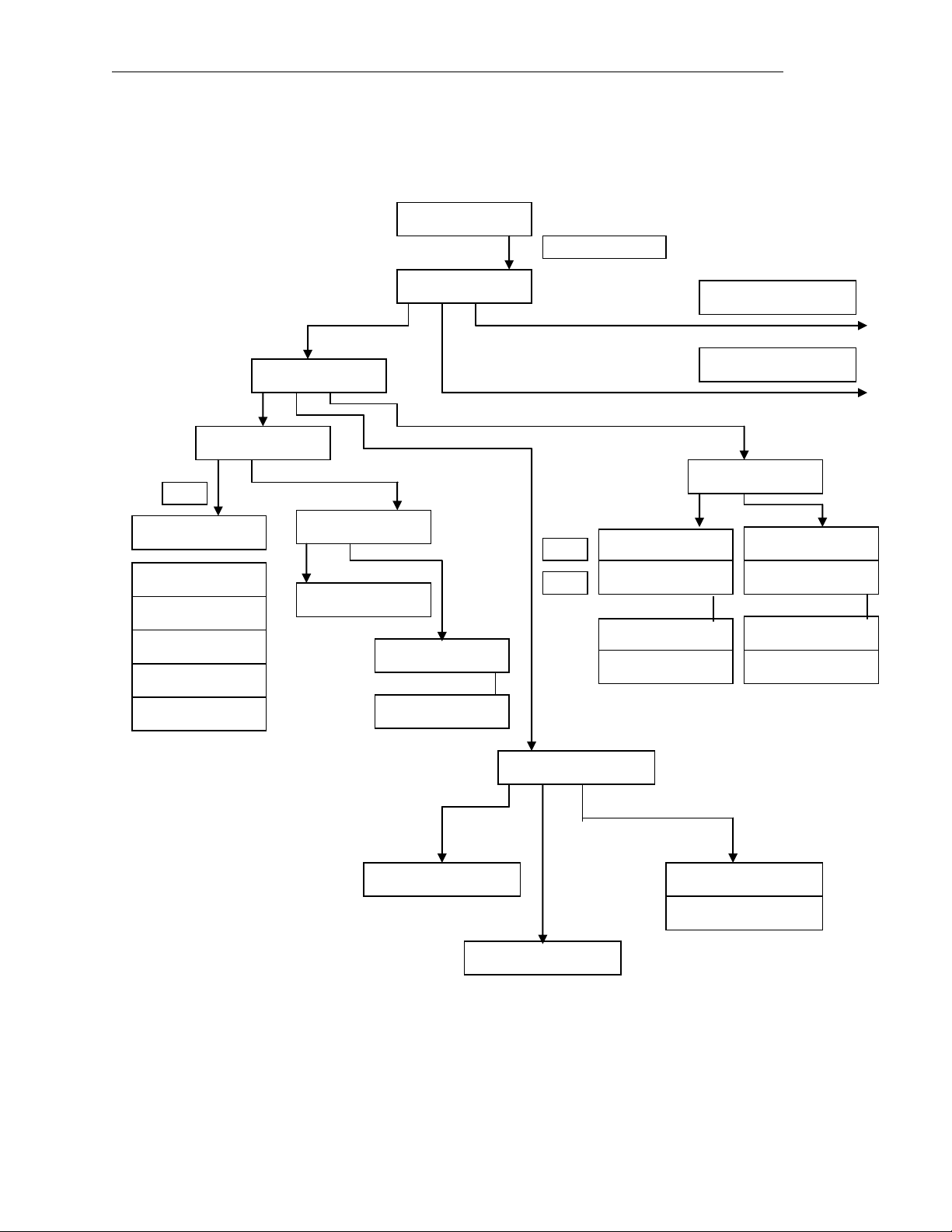
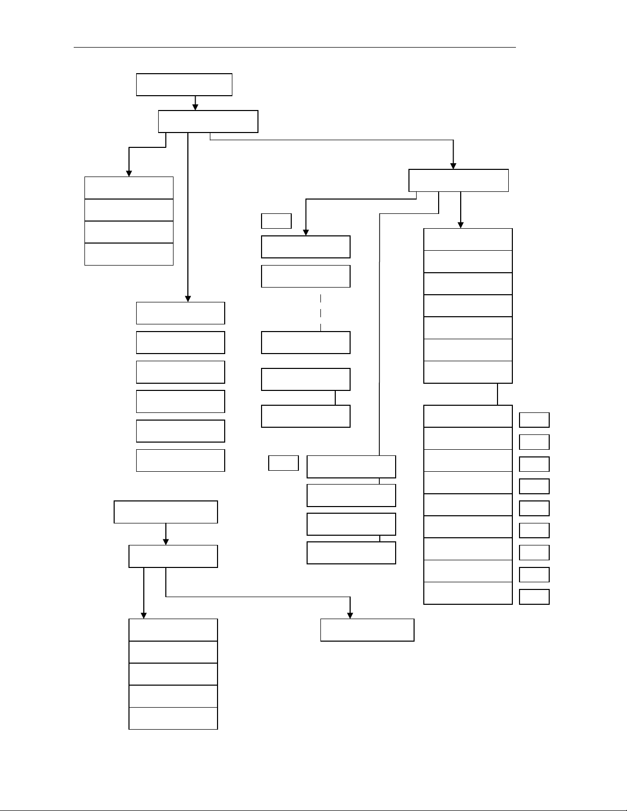
1.3.1. Menu Tree
*
*
*
*
*
* ONLY available for MODBUS
Fox Thermal Instruments Inc., 399 Reservation Road, Marina, CA 93933 Page 3
Page 8
Model FT2 101364
FLOW PARAMETER 1
SIM UNT PRM EXIT
FLOW PARAMETERS
FloSim=0 SCFM
CHG OK
TmpSim=0 °F
CHG OK
CsvSim=0 V
CHG OK
FLO UNT=SCFM
NXT OK
TMP UNT=°F
NXT OK
TmpRef= 60 °F
CHG OK
PRES UNT=mmHG
NXT OK
PresRef=760
CHG OK
DNS = 0.9234 Kg/M3
CHG OK
FLOW PARAMETER 2
CAL SPC PRM EXIT
Volt1=0.9345
CHG PRV NXT EXIT
Flo1=0.0
CHG PRV NXT EXIT
Volt20=1.245
CHG PRV NXT EXIT
Flo20=3756
CHG PRV NXT EXIT
CalDate= 12/7/03
CHG OK
RtdHiRes=282.4 Ohm
CHG OK
RtdHi_F=300 °F
CHG OK
RtdLoRes=192.1 Ohm
CHG OK
RtdLo_F=70 °F
CHG OK
AdcF=0.0005893
CHG OK
Rx= 49.9 Ohm
CHG OK
Restore Database?
Yes No
DISPLAY/PASSWORD
DSP1L1= Flo Rate
NXT OK
DSP1L2= Flo Total
NXT OK
DSP2L1= Temp
NXT OK
DSP2L2= Elps time
NXT OK
ALTERNATE=Off
NXT OK
DISPLAY/PASSWORD
DSP PSW EXIT
PASSWD=1234
CHG OK
Level2
Level 2
Level2
Level2
Level2
Level2
Level2
Level2
ShResOfst=0
CHG OK
Tsv_rt=0.197656
CHG OK
R20_value=2.5
CHG OK
Level2
Level2
Level2
ENABLE SIM ?
YES NO
Cutoff=1.0 SCFM
CHG OK
A2=0.0865 FT^2
CHG OK
Filter=0.5
CHG OK
HiFloAlm=0 SCFM
CHG OK
LoFloAlm=0 SCFM
CHG OK
HiTmpAlm=0 °F
CHG OK
LoTmpAlm=0 °F
CHG OK
Reset CRC?
Yes No
K fact = 0 %
CHG OK
MaxRTD9 = 16 Ohm
CHG OK
**
** ONLY for Kg/ and LB/
Page 4 Fox Thermal Instruments, Inc., 399 Reservation Road, Marina, CA 93933
Page 9
101364 Model FT2
1.4. Analog 4-20 mA outputs
Two industry standard 4-20 mA isolated analog outputs are available to monitor flow rate and
temperature. Each output is scalable for the 4 and 20 mA values. See the programming section for
details.
1.5. Discrete I/O
One discrete input is available for remote resetting of the totalizer and elapsed time.
One isolated discrete output is available for generating an alarm for High or Low limits for temperature
or flow rate, if the output is not used for the pulse output.
1.6. Frequency/Alarm Output
One isolated frequency output is available to monitor flow rate and is typically used for totalization.
The maximum frequency output is 100 Hz. The output can be scaled by using the flow setting and
maximum frequency or using the pulse per unit or unit per pulse method of entry. The isolated digital
output can be used either as a frequency output or an alarm output but not both. The output type is
selected by JP1.
1.7. Local Display Options
An optional front panel with a LCD display and keypad is available to display measured data and
allow field programming of the flowmeter. The display is an easy to read, two-lines, 16 characters
backlit LCD and 4 function keys. The local display/keypad module is wired to the FT2 electronics
through connector TS6. TS6 is on the main board. Refer to the Programming section for a detailed
explanation of its usage.
1.8. Communication Features
The FT2 offers a RS232 serial link that communicates to a Palm™ PDA handheld or with a PC
application for data display and programming. Also, RS485 is available to connect to the optional
front panel with an interface to a specific bus converter (Profibus, DeviceNet or Ethernet). The RS485
can connect directly as an optional Modbus interface. Only one bus protocol is supported at one time.
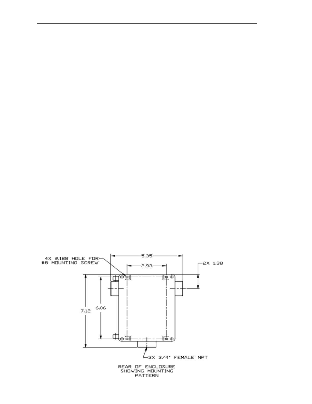
1.9. Dimension Details
Figure 1-2 Enclosure Mounting Dimensions
Rear View of
enclosure without
sensor or conduit.
AC power enters on
one side, DC power
and signals enter on
the other side.
Fox Thermal Instruments Inc., 399 Reservation Road, Marina, CA 93933 Page 5
Page 10
Model FT2 101364
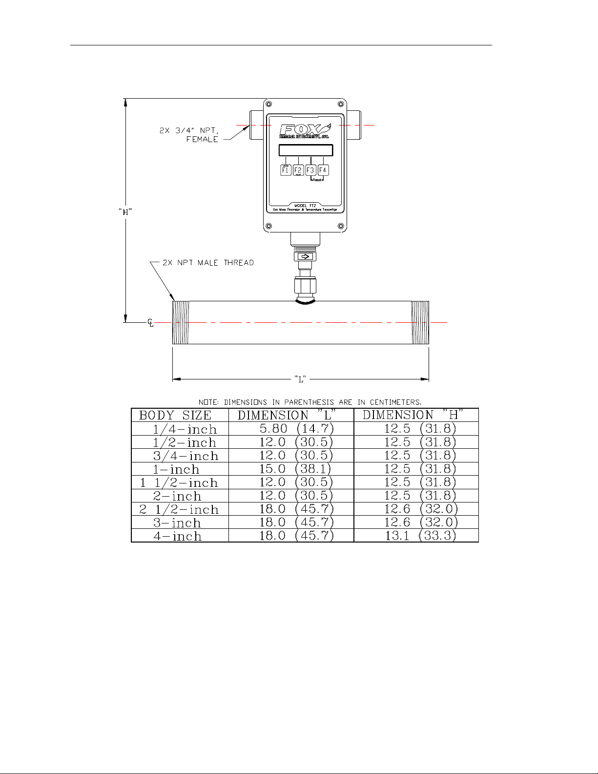
Figure 1-3 Dimensions for Flow Body Style with NPT Connections
Page 6 Fox Thermal Instruments, Inc., 399 Reservation Road, Marina, CA 93933
Page 11

101364 Model FT2
Figure 1-4 Dimensions for Flow Body with Flange Connections
Fox Thermal Instruments Inc., 399 Reservation Road, Marina, CA 93933 Page 7
Page 12
Model FT2 101364
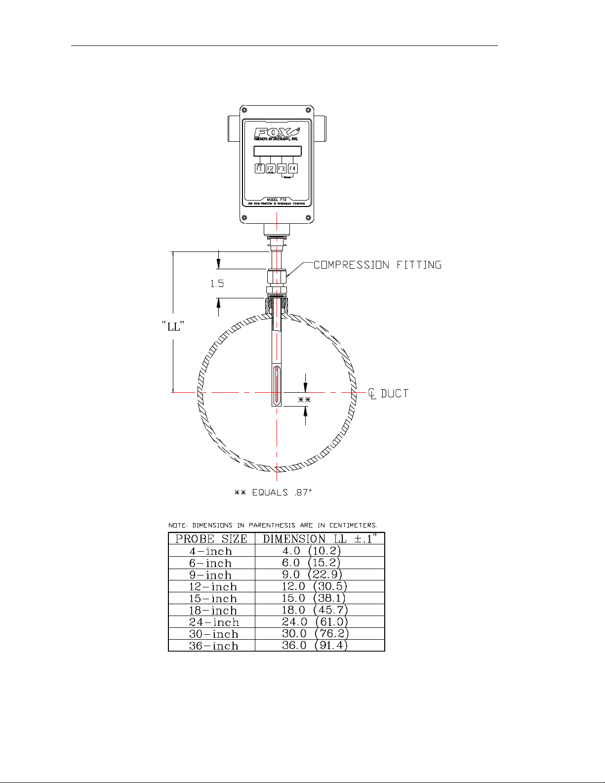
Figure 1-5 Dimensions for Insertion Style
Page 8 Fox Thermal Instruments, Inc., 399 Reservation Road, Marina, CA 93933
Page 13

101364 Model FT2
Figure 1-6 Dimensions for Remote NEMA 4 Enclosure
Fox Thermal Instruments Inc., 399 Reservation Road, Marina, CA 93933 Page 9
Page 14
Model FT2 101364
2. Installation
2.1. Scope
This section describes how to install the FT2 flowmeter and how to get started.
The following, general precautions should be observed:
a. Exercise care during handling to avoid damaging the probe, sensor or enclosure.
b. The enclosure cover must be closed except during installation and programming.
c. Mounting FT2 in direct sunlight can cause the temperature inside the enclosure to increase
beyond design limits, resulting in failure of the LCD display and reduced component life. It
is recommended that a sunshade be installed to avoid direct sunlight.
d. Ensure that the arrow on the flow body is pointing in the direction of flow.
e. Do not install the FT2 enclosure near an igniter, igniter controller or switching equipment.
f. Do not install an external power supply in a cabinet containing an igniter controller or
switching equipment.
g. Do not power the power supply with an AC power source that is also used to power an igniter
or igniter controller.
2.2. Insertion Style
2.2.1. Mounting – Insertion Style
The Model FT2 is mounted through a ¾-inch hole and a ¾-inch female NPT half coupling
provided in the customer’s pipe. Installation procedures must be a combination of end user’s best
engineering practices, in compliance with local codes, and manufacturer’s recommendations.
Insertion style flowmeters are not recommended for pipes smaller than 1½”.
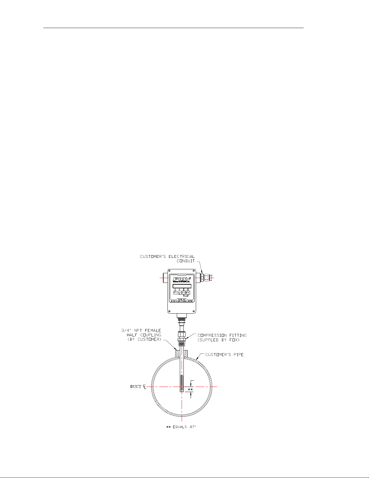
Figure 2-1 Insertion Style
Page 10 Fox Thermal Instruments, Inc., 399 Reservation Road, Marina, CA 93933
Page 15
101364 Model FT2
2.2.2. Installation Depth
Note: Some flowmeters are shipped with sensors that have equal length elements (see Figure 2-2).
Others are shipped with the sensor elements that are offset (see Figure 2-3). The sensor type supplied
was selected at the factory to be the best suited for your application. Follow the appropriate sensor
orientation instructions below. (Refer to Figure 1-5)
a. Install the compression fitting into the ¾-inch female NPT half coupling.
b. When installing in a 2-inch pipe or larger, install the end of the probe 0.87-inch past the
centerline of the pipe and tighten the compression fitting nut. Refer to Figure 2-1.
c. When installing into a 1½-inch pipe carefully install the probe into the pipe until it touches the
opposite wall and pull back 0.1-inch. Tighten the compression fitting nut.
Caution: Once the compression fitting is locked onto the probe, the probe can be removed or
rotated, but the insertion depth is locked in place.
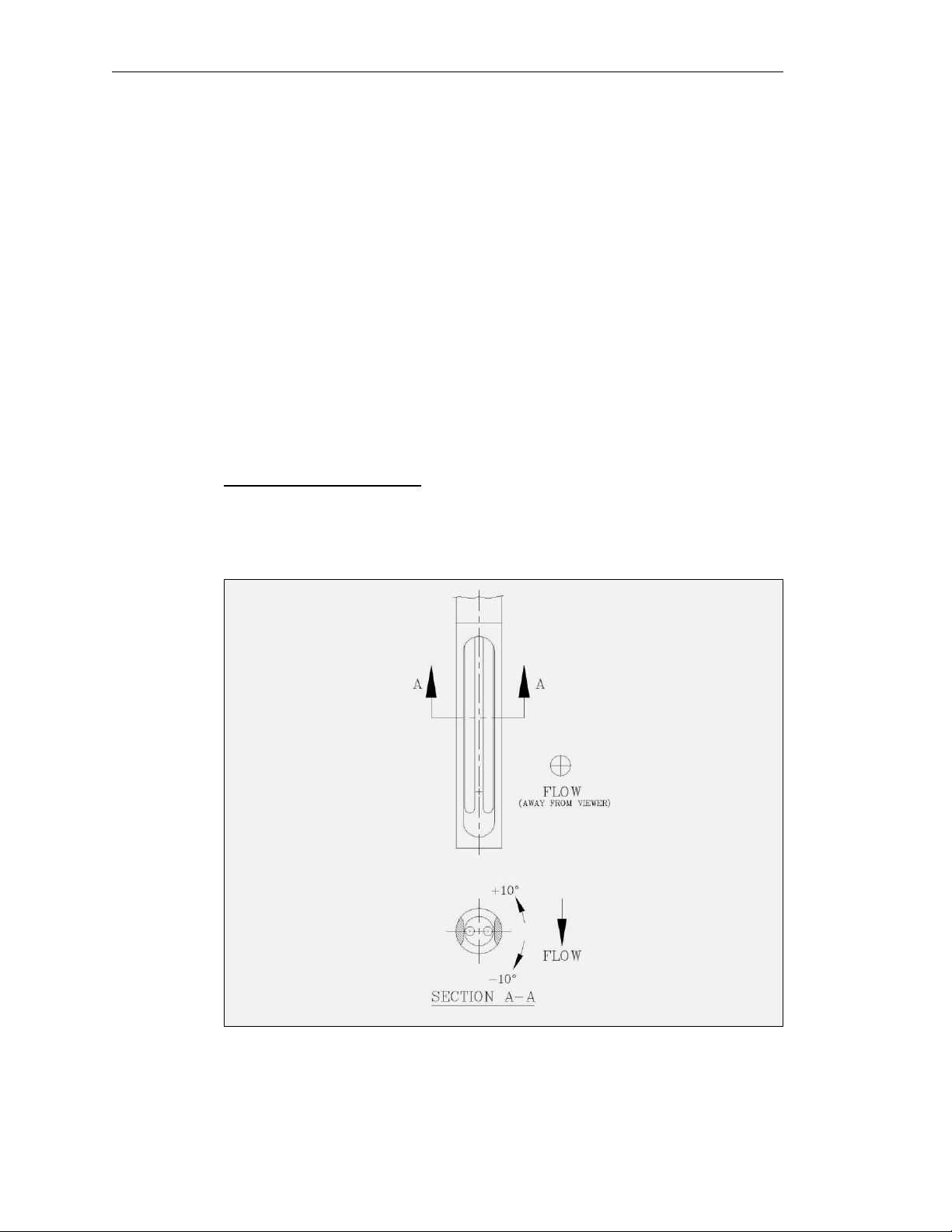
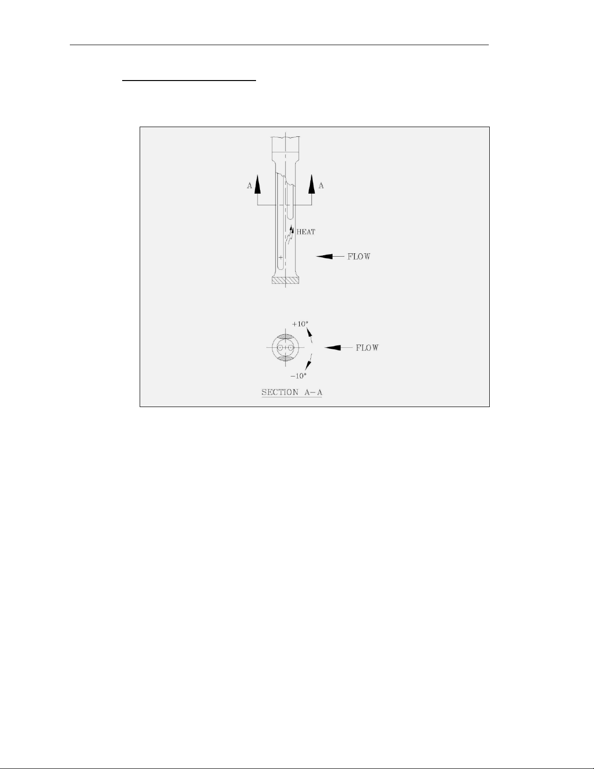
2.2.3. Sensor Orientation
Equal length sensor elements:
Install flowmeter with both sensor elements facing the flow stream within +/-10 degree.
Figure 2-2. Equal Length Sensor Elements.
Fox Thermal Instruments Inc., 399 Reservation Road, Marina, CA 93933 Page 11
Page 16
Model FT2 101364
Unequal length sensor elements:
Install the shorter sensor element upstream from the longer one.
Figure 2-3 Unequal Length Sensor Element
Note: In extreme low flow measurements (below 30 standard feet per minute), convection heat
from the longer probe can affect the shorter probe. In these applications, chose a mounting that
prevents this from occurring (ex. Horizontal mounting).
Page 12 Fox Thermal Instruments, Inc., 399 Reservation Road, Marina, CA 93933
Page 17
101364 Model FT2
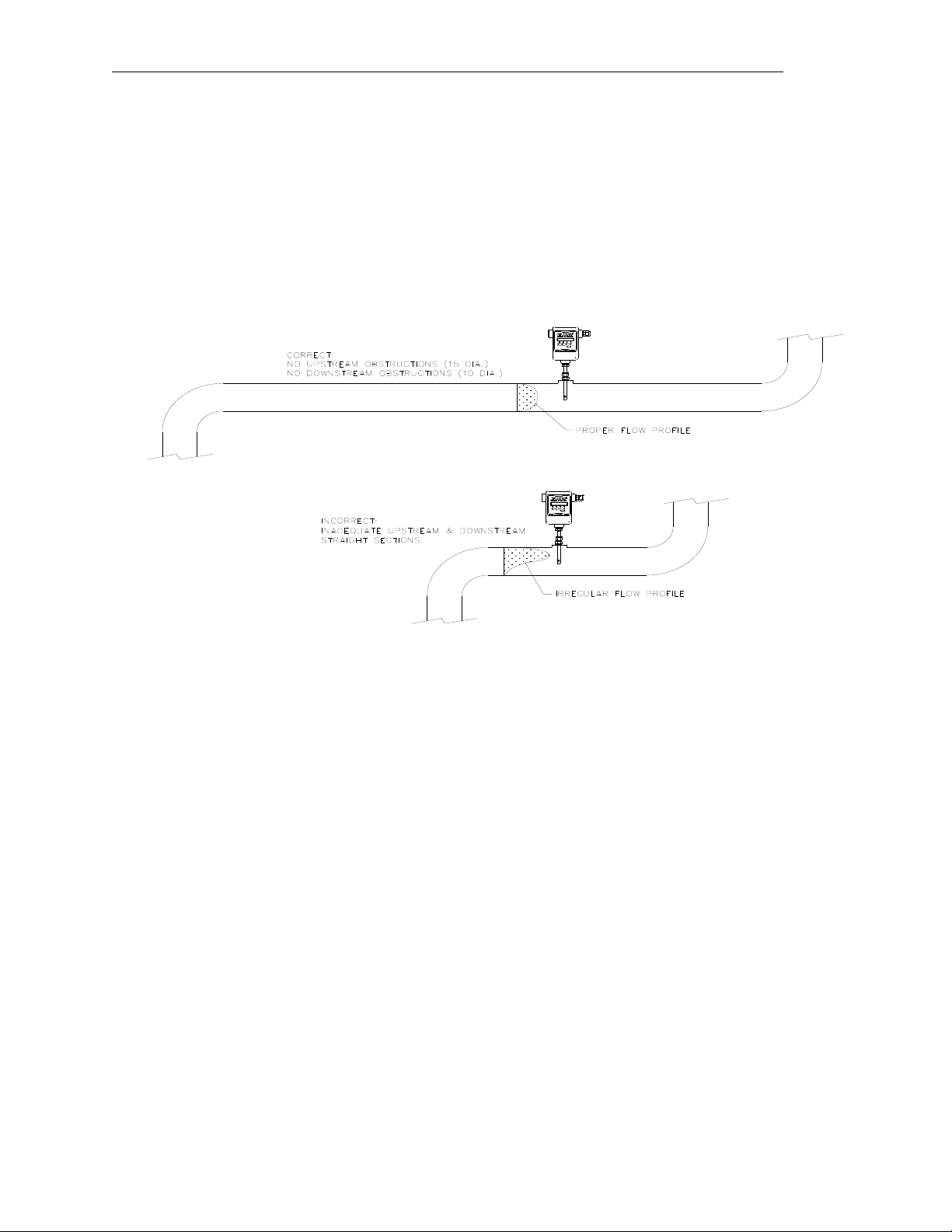
2.2.4. Flowmeter Placement - Insertion Style
Install the Model FT2 Insertion style flowmeter so that it is far enough away from bends in the
pipe, obstructions, or changes in line sizes to ensure a consistent flow profile. Fifteen diameters of
straight pipe upstream and ten downstream are recommended.
Figure 2-4 Flowmeter Placement – Insertion Style
Fox Thermal Instruments Inc., 399 Reservation Road, Marina, CA 93933 Page 13
Page 18
Model FT2 101364
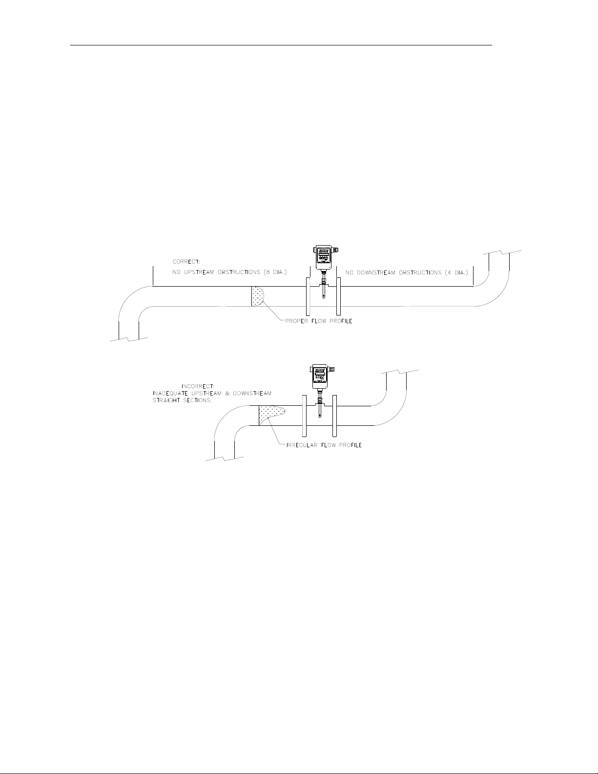
2.2.5. Flowmeter Placement - Flow Body Style
Install the Model FT2 Inline style flowmeter so that it is far enough away from bends in the pipe,
obstructions, or changes in line sizes to ensure a consistent flow profile. Eight diameters of
straight pipe upstream and four downstream are recommended.
The Model FT2 is welded, threaded or flanged to the customer’s pipe. Care should be taken to
ensure that the diameter of the mating pipe is the same diameter as the Model FT2 flow body or
errors in flow readings can occur. Installation procedure should be a combination of the end
user’s best engineering practices, in compliance with local codes, and the manufacturer’s
recommendations.
Figure 2-5 Flowmeter Placement - Flow Body Style
Page 14 Fox Thermal Instruments, Inc., 399 Reservation Road, Marina, CA 93933
Page 19

101364 Model FT2
Figure 2-6 Flow Body Style
2.2.6. Flow Body Orientation
Install the flow body so that the arrow on the outside of the flow body is in the direction of flow.
This will ensure the correct sensor orientation.
Note: In extreme low flow measurements (below 30 standard feet per minute), convection heat
from the longer probe may affect the shorter probe (see Figure 2-3, View A-A). In these
applications, chose a mounting orientation that prevents this from occurring (ex. horizontal
mounting).
Figure 2-7 Flow Body Orientation
Fox Thermal Instruments Inc., 399 Reservation Road, Marina, CA 93933 Page 15
Page 20

Model FT2 101364
3. Start Up
3.1. Scope
This section describes the steps needed to get the FT2 Flowmeter running.
The enclosure has two separate conduit entries to maintain separation between AC input power and
output signal wiring. To eliminate the possibility of noise interference, use a separate cable entry for
AC power and signal lines.
Figure 3-1 Input Wiring
Note: All references to conduit orientation are from the Front Panel perspective.
3.2. Wiring
Warning! All installation procedures must be performed with power Off.
All plumbing and electrical installations of flow meters must be a combination of the end user’s best
engineering practices, in compliance with local codes, and the manufacturer’s recommendations.
Do not install the FT2 enclosure near an igniter, igniter controller or switching equipment.
Do not install an external power supply in a cabinet containing an igniter controller or switching
equipment.
Do not power the power supply with an AC power source that is also used to power an igniter or
igniter controller.
Wiring Installation
Warning! This flowmeter contains components that can be damaged by static electricity. You
must discharge yourself by touching a grounded steel pipe or other grounded steel material prior
to working inside this flowmeter.
Wiring is accomplished by loosing the 4 captive screws holding the cover of the enclosure to expose
the electronic circuit boards. Bring customer supplied wires into the enclosure through the conduit
access on the sides of the enclosure. Cut wires for a 2-inch service loop. Use stranded copper wire, no
larger than 16-gauge. If you are using the optional AC power supply, connect the two AC wires and
the safety ground to the TS7 connector marked as AC (bring AC wires in through the left-hand conduit
hub). If an external 24 VDC power source is used, it is recommended that a twisted shielded pair cable
be used. Connect the wires to connector TS1 being careful to connect with the correct polarity (bring
DC wires in through the right-hand conduit hub).
Page 16 Fox Thermal Instruments, Inc., 399 Reservation Road, Marina, CA 93933
Page 21

101364 Model FT2
Signal Wires
Always use a separate shielded cable for each output signal, select the proper wire gauge. The
recommended wire gauge is 18 to 22 AWG. The cable shield should not be connected at the
flowmeter, the shield should be connected at the AC ground terminal at the power supply or
instrumentation AC ground terminal.
3.2.1. Power Input Wiring and Grounding
If the optional AC power supply is supplied by FOX, the input power can be 85 to 250 VAC. If the
customer supplies an external power supply, it must supply 24 VDC +/- 10 %, with a minimum of one
amp.
The enclosure must be properly grounded with a quality earth ground to protect the electronics from
static discharges. It is recommended that 16 gauge, stranded wire be used.
Figure 3-2 Power Input Wiring
Fox Thermal Instruments Inc., 399 Reservation Road, Marina, CA 93933 Page 17
Page 22

Model FT2 101364
Important note: The load
resister on the Fox
Flowmeter 4 to 20 mA
signal is typically 250
ohms and is located in or
at the customers PLC or
DCS. A 250 ohm resister
in the 4 to 20 mA line will
result in a 1 to 5 VDC
signal to the PLC or DCS.
Some PLC/DCS
equipment has the load
resister built into the unit;
please refer to the
PLC/DCS technical
manual. Do not exceed a
600 ohm load on the Fox
Flowmeter 4 to 20 mA
signal.
3.2.2. 4 to 20 mA Output Wiring
Bring the 4 to 20 mA wiring in through the right-hand conduit hub. Connect FLOW RATE 4 to 20
mA output to TS2, 1(+) & 2(-). Connect TEMPERATURE 4 to 20 mA output to TS2, 3(+) & 4(-).
Figure 3-3 Isolated Wiring for the 4-20mA Outputs
Page 18 Fox Thermal Instruments, Inc., 399 Reservation Road, Marina, CA 93933
Figure 3-3A Non-Isolated Wiring for the 4-20mA Outputs
Page 23

101364 Model FT2
3.2.3. Frequency/Alarm Output Wiring
Bring frequency/alarm wiring in through the right-hand conduit hub. Connect to TS2, 5(+) & 6(-). The
frequency/alarm output is an open collector circuit capable of sinking a maximum of 10 mA of current.
The frequency output is selected when JP1 pins 1 & 2 are connected together using the shunt provided.
The alarm output is selected when JP1 pins 2 & 3 are connected together. Only one of the options can
be active at one time.
Figure 3-4 Frequency/Alarm Output Wiring
Fox Thermal Instruments Inc., 399 Reservation Road, Marina, CA 93933 Page 19
Page 24

Model FT2 101364
3.2.4. RS485 Wiring
W1 jumper is to terminate the bus with a 121ohm resistor and should only be installed on the last
instrument of the daisy chain. W3 and W4 are used for half duplex operation. (W3 connects TX+ &
RX+, W4 connects TX- & RX-).
Figure 3-5 RS485 Wiring and Configuration
Page 20 Fox Thermal Instruments, Inc., 399 Reservation Road, Marina, CA 93933
Page 25

101364 Model FT2
3.2.5. Remote Switch Wiring
A remote switch can be used to reset the Totalizer and elapsed time, if enabled by the
programming mode. The switch contacts are de-bounced on the FT2 board. There is no polarity
requirement on these connections. Use TS2-12 and TS2-13.
When the 2 curve option is ordered the switch can be used to switch between curves.
Figure 3-6 Remote Switch Wiring
Note: Remote switch functionality needs to be enabled using the display front panel.
See programming section 4.1.5.1
Fox Thermal Instruments Inc., 399 Reservation Road, Marina, CA 93933 Page 21
Page 26

Model FT2 101364
3.2.6. Local Sensor Wiring (4 wires)
Note: Sensor terminations are performed at the factory except when Remote Electronics are provided.
Figure 3-7 Local Sensor Wiring (4 Wire)
Page 22 Fox Thermal Instruments, Inc., 399 Reservation Road, Marina, CA 93933
Page 27

101364 Model FT2
3.2.7. Local Sensor Wiring High Temperature (5 Wire)
Note: Sensor terminations are performed at the factory except when Remote Electronics are provided.
Figure 3-8 Local Sensor Wiring High Temperature (5 Wire)
Fox Thermal Instruments Inc., 399 Reservation Road, Marina, CA 93933 Page 23
Page 28

Model FT2 101364
3.2.8. Remote Sensor Wiring Installation
Note: Remote wiring is only required when the Remote Electronics options is provided.
Five wire shielded cable required. The shielded cable should be ran through a separate grounded steel
conduit. (No other cables or wires in the conduit.)
Connect sensor wires as follows: Red wires to terminals # 1 and # 2, white wires to # 5 and # 6 and
yellow wire to # 3, cable shield to # 4 (see Figure 3-8).
Connect other end to connector TS8 (see Figure 3-7) on the main FT2 board as follows:
Red wires to TS8 pin 1 & 2, white wires to TS8 pins 5 & 6 and yellow wire to TS8 pin 3.
If you are using your own cable, make sure that the cable does not exceed 100 feet and has a wire
resistance that does not exceed one ohm (18 AWG recommended). Do not connect the shield at the
FT2 enclosure end. On the FT2 board, make sure that the jumper W2 is not across both pins when a
5-wire sensor is supplied (see Figure3-8).
Figure 3-9 Remote Sensor Wiring (5 wire) (see also Figure 1-6)
Page 24 Fox Thermal Instruments, Inc., 399 Reservation Road, Marina, CA 93933
Page 29

101364 Model FT2
3.3. Start Up Sequence
The program automatically enters the Run/Measure mode after power up. If the Local display is
installed, the screen will show the software versions for the FT2 and the display module.
Refer to section 4.1 Programming using the Local Display. Programming of the flowmeter can also
be accomplished using a Palm™ handheld or a Windows-based PC program. The PC requires a null
modem connection.
The device used to program the unit must have FOX software installed, prior to beginning the
programming operation. FT2 View required for Windows.
3.4. Measurement Mode
In the measurement mode, there are 4 different display screens (display 1, 2, 3 and a prompt screen to
enter the programming mode), 2 display screens are user programmable (refer to section 4.1.7).
Scrolling through the display is accomplished by pressing the F1 or F2 key to view the next or
previous screen. Pressing the F1 and F2 keys at the same time enters the Engineering Menu screens
(display 10 through 22). Keys F1 and F2 are use to scroll through the different screens and key F4 to
EXIT to the normal menu screen.
Pressing the F3 & F4 keys at the same time brings up the Total Reset screen prompt.
3.5. 4 to 20 mA Outputs
The two isolated analog 4-20 mA outputs are available at connector TS2. Pins 1(+) & 2(-) are used for
the analog output associated with the flow rate. Pins 3(+) & 4(-) are used for the 4-20 mA output
associated with the temperature. Both require power for the loop to operate. Refer to Figure 3-3 for
wiring.
3.6. Frequency/Alarm Output
The frequency or alarm isolated output is available at connector TS2 pins 5(+) & 6(-). When using the
frequency output, it can be scaled to represent flow rate for totalizing or flow rate indication. Refer to
Figure 3-4 for wiring.
Fox Thermal Instruments Inc., 399 Reservation Road, Marina, CA 93933 Page 25
Page 30

Model FT2 101364
1456.5 SCFM
123456 SCF
Elp=14.6 HR
88.5 °F
Alarm=None
Elp=14.6 H
SET PARAMETER?
No Yes
F2
F1
F1
F1
F2
F2
F3
F4
F4
F2
F1
3.7. Local Display Screens
3.7.1. Display Screens
F1 key: Moves up one screen
F2 key: Moves down one screen
Display #1 (User programmable screen)
Enter “totalizer reset screen” when F3 & F4
are pressed at the same time.
Display #2 (User programmable screen)
Enter “engineering display screens” when
F1 & F2 are pressed at the same time
Display #3 (Fixed screen)
Prompt screen to enter programming mode
Display #4
Enter programming screen
Requires correct password. Default is 1234.
Note: CRC ERROR will flash on the display if a CRC Error is detected while reading the EEPROM.
Alarm Code 36 will be displayed in the Alarm Display. Refer to 4.1.14 RESET CRC.
Page 26 Fox Thermal Instruments, Inc., 399 Reservation Road, Marina, CA 93933
Page 31

101364 Model FT2
Flo=1255 SCFM
Csv=0.45678 Volt
Csv=1456.5 cnt
Vel=123456 FT/H
CsvFlt=1456.2 cnt
Vel=23456.1 M/H
TsiAvr = 761.6 cnt
TsvAvr=932.6 cnt
Tsi=0.8765 Volt
Tsv=0.8675 Volt
Tsi=0.09827 Amp
Tsi=247.8 Ohm
RTD9 = 11.9 Ohm
GasTemp = 88.5 °F
Flo_420=4091 cnt
Tmp_420 = 2356 cnt
Feq = 2345 cnt
Alarm = None
FloHi = 1000 SCFM
FloLo = 0 SCFM
TmpHi = 100 °F
TmpLo = 50 °F
ELP = 11.77 HR
Stat(hex)=0000
Vers=FT2 V1.40
Display V1.22
Back to Display #10
Pwr_cyc=0
Err_tot=0
3.7.2. Engineering Screens
Pressing F1 and F2 keys at the same time in the normal mode, brings the engineering screens.
These screens display internal parameters of the FT2, which are used by Fox service personnel.
Display # 10 F1 key: Move up one screen
F2 key: Move down one screen.
F4 key: Exit engineering screen.
Display #11
Display #12
Display #13
Display #14
Display #15
Display #16
Display #17
Display #18
Display #19
Display #22
Display #20
Display #23
Display #21
Fox Thermal Instruments Inc., 399 Reservation Road, Marina, CA 93933 Page 27
Page 32

Model FT2 101364
Code
Description
12
Power up Initializing
13
Flow rate above high limit
14
Flow below low limit
15
Temperature above high limit
16
Temperature below low limit
22
Sensor out of range
23
Velocity out of calibration table range
24
Check settings
25
Simulation mode
26
Frequency output over range
32
4 to 20 mA for flow rate is out of range
33
4 to 20 mA for temperature is out of range
34
ANYBUS communication error
35
RTC Error
36
EEPROM CRC Error
37
Totalizer error detected
Reset Total ?
NO YES
F1
F2
F3
F4
PASWD:
UP DN NXT OK
F1
F2
F3
F4
3.8. Resetting Total and Elapsed Time
Pressing F3 and F4 at the same time in the normal running mode brings the prompt to reset the
totalizer and elapsed time:
If the password is active the program will prompt the user to enter the password:
If the password is correct, the reset will be performed, otherwise a “Wrong Password” message will be
displayed briefly before returning to the normal mode.
Note: To disable the programmable password set it to “0”.
3.9. Alarm Indications
Alarm indications are provided to indicate any malfunctions, out of range values or saturated analog
outputs.
The following list is a description of alarm codes:
Page 28 Fox Thermal Instruments, Inc., 399 Reservation Road, Marina, CA 93933
Page 33

101364 Model FT2
VALUE = 0.91234
CHG OK
F1
F2
F3
F4
VALUE = 0.91234
UP DN NXT OK
F1
F2
F3
F4
FLO UNT = SCFM
NXT OK
F1
F2
F3
F4
4. Programming
4.1. Programming using the Local Display
4.1.1. Data Entry using the local display module
There are 2 basic types of menu entries: one for changing value or string and one for selecting
from a selection list.
4.1.1.1. To Change a Value or String :
Press CHG (F1) key to change the value, OK (F4) to accept the value.
Press the UP (F1) or DN (F2) key to select a new digit or character, the cursor points to
the selected digit. Press NXT (F3) to select the next digit and OK (F4) to accept the
entry.
Note: If the UP (F1) or DN (F2) key is held down for more the 1 second, the program
will progressively select new digits at increasing speed as time increases.
4.1.1.2. To Select from a List:
Fox Thermal Instruments Inc., 399 Reservation Road, Marina, CA 93933 Page 29
Press NXT (F1) key repeatedly until the correct selection is made and OK (F4) key to
accept the entry.
Page 34

Model FT2 101364
SET PARAMETERS ?
No Yes
F1
F2
F3
F4
PASWD:_
UP DN NXT OK
F1
F2
F3
F4
SET PARAMETERS
I/O FLO DSP EXIT
F1
F2
F3
F4
SET I/O
I/O FEQ 420 EXIT
F1
F2
F3
F4
4.1.2. Entering the Programming Mode
To enter the programming mode, press the F1 or F2 key repeatedly in the normal running mode
until the following screen is shown:
Press YES (F4) and the following screen will prompt the user to enter the password if it is active:
Enter the correct password, follow the instructions for changing a value as specified in section
4.1.1. The default Level 1 password is “1234”.
If the wrong password is entered, the message “Wrong Password” will be displayed for a few
seconds and then returns to the programming entry screen.
If the password is accepted, the following screen will be shown:
This is the base screen for the programming mode.
Press EXIT (F4) repeatedly until “Normal Mode” is seen briefly to exit the programming
mode.
4.1.3. Analog 4-20 mA Output
The following menu allows the scaling of the analog 4-20 mA outputs.
From the base screen, press I/O (F1) and then in the next screen press 420 (F3).
Page 30 Fox Thermal Instruments, Inc., 399 Reservation Road, Marina, CA 93933
Page 35

101364 Model FT2
20 mA = 3751 SCFM
CHG OK
F1
F2
F3
F4
4 mA = 0 SCFM
CHG OK
F1
F2
F3
F4
FREQUENCY OUTPUT
P/U U/P FEQ EXIT
F1
F2
F3
F4
SET 4-20 MA
FLO TMP EXIT
F1
F2
F3
F4
Then select either FLO (F1) or TMP (F2) for flow rate or temperature channel.
Enter the value for the 20 mA and press OK (F4) key to accept setting.
Then the following screen will show:
Enter the value for the 4 mA and press OK (F4).
Note: 4 mA is normally set to 0.
Press EXIT (F4) repeatedly until “Normal Mode” is seen briefly to exit the programming mode.
Note: When the flow rate exceeds the programmed value for the 20 mA set point, the analog
output will stay at 20 mA and an alarm code will be generated.
4.1.4. Frequency Output
From the base screen, press I/O (F1) and then FEQ (F2)
Fox Thermal Instruments Inc., 399 Reservation Road, Marina, CA 93933 Page 31
The frequency output can be configured in three different ways: (1) specifying a maximum
frequency to a defined maximum value of flow rate, (2) specifying how many flow unit total per
pulse, U/P (i.e. 0.1 lb per pulse) or (3) specifying how many pulses per unit, P/U, of mass. All
these approaches are equivalent.
Use P/U (F1) to enter pulse per unit, U/P (F2) for Unit per pulse and FEQ (F3) to enter the flow
and maximum frequency to scale the frequency output.
Page 36

Model FT2 101364
PLS/UNT = 100
CHG OK
F1
F2
F3
F4
UNT/PLS = 0.01
CHG OK
F1
F2
F3
F4
MaxFreq=98.52 Hz
CHG OK
F1
F2
F3
F4
Maxflo=2000 SCFM
CHG OK
F1
F2
F3
F4
When data is entered with any of the 3 methods, the other values will be re-calculated according to
the settings.
4.1.4.1. Entering data in Pulse per Unit:
Press P/U (F1) and the following screen will show:
Press CHG (F1) to change the setting and then OK (F4) to accept entry.
The value entered is in pulse per selected flow unit total (i.e. 10 pulses per SCF)
4.1.4.2. Entering data in Unit per Pulse:
Press U/P (F2) and the following screen will show:
Press CHG (F1) to change the setting and then OK (F4) to accept entry.
The value entered is in unit per pulse (i.e. 0.01 flow unit total per pulse)
4.1.4.3. Entering data with flow and maximum frequency:
Press FEQ (F3) and the following screen will show:
Enter the maximum frequency and press OK (F4)
(Maximum frequency should not exceed 100 Hz)
The next screen will show:
Page 32 Fox Thermal Instruments, Inc., 399 Reservation Road, Marina, CA 93933
Page 37

101364 Model FT2
SET I/O
I/O FEQ 420 EXIT
F1
F2
F3
F4
SET I/O
COM CTC EXIT
F1
F2
F3
F4
CONTACTS
INP ALM EXIT
F1
F2
F3
F4
INP = Not Used
NXT OK
F1
F2
F3
F4
Note: When the flow rate exceeds the maximum frequency set point, the output will stay at that
maximum frequency but the FT2 will issue an alarm code.
4.1.5. Discrete Input/Output
To program the discrete input or output, press I/O (F1) key from the base menu
Then press I/O (F1) again:
Then press CTC (F2) to select contact input/output
4.1.5.1. For Discrete Input Settings:
Press INP (F1) key to select input, then menu will display:
Press NXT (F1) repeatedly until the correct selection is shown and then press OK (F4) to
accept the setting.
Selections are: Not used
Tot Reset to reset the totalizer
Switch Crv Multi Curve Option Only
Fox Thermal Instruments Inc., 399 Reservation Road, Marina, CA 93933 Page 33
Page 38

Model FT2 101364
ALM = HiFloAlm
NXT OK
F1
F2
F3
F4
HiFloAlm = 1000 SCFM
CHG OK
F1
F2
F3
F4
SET I/O
I/O FEQ 420 EXIT
F1
F2
F3
F4
4.1.5.2. For Discrete Output Setting:
Press ALM (F2) key to select alarm output, then menu will display:
Press NXT (F1) repeatedly until the correct selection is shown and then press OK (F4) to
accept the setting.
Selections are: Not used
HiFloAlm for High Flow Alarm
LoFloAlm for Low Flow Alarm
HiTempAlm for High Temperature Alarm
LoTempAlm for Low Temperature Alarm
If a Limit type is selected, then the menu will display:
Enter the limit value to trigger the contact alarm output and then press OK (F4) to accept
the setting.
Press EXIT (F4) repeatedly until “Normal Mode” is seen briefly to exit the programming
mode.
The JP1 selection jumper needs to be installed between pin 2 & 3 on the main FT2
board to select the isolated digital output for the alarm.
4.1.6. RS485 Serial Communication Settings
To program the RS485 settings, press I/O (F1) key from the base menu
Then press I/O (F1) again:
Page 34 Fox Thermal Instruments, Inc., 399 Reservation Road, Marina, CA 93933
Page 39

101364 Model FT2
SET I/O
COM CTC EXIT
F1
F2
F3
F4
Bus=Modbus
NXT OK
F1
F2
F3
F4
Baud=9600
NXT OK
F1
F2
F3
F4
Parity=None
NXT OK
F1
F2
F3
F4
Press COM (F1) to select RS485 communication bus type and then OK (F4)
Selections are: None
Modbus
Profibus
Ethernet
DeviceNet
Note: Special hardware is needed to use Profibus, DeviceNet and Ethernet
For Modbus selection only
Press NXT (F1) to select the baud rate and press OK (F4)
Selections are: 19200
9600
4800
2400
1200
For Modbus selection only
Press NXT (F1) to select the parity and press OK (F4)
Selections are: NONE
ODD
EVEN
Fox Thermal Instruments Inc., 399 Reservation Road, Marina, CA 93933 Page 35
Page 40

Model FT2 101364
DISPLAY/PASSWORD
DSP PSW EXIT
F1
F2
F3
F4
DSP1L1 = Flo Total
NXT OK
F1
F2
F3
F4
Data Bit=8
NXT OK
F1
F2
F3
F4
Stop Bit=1
NXT OK
F1
F2
F3
F4
Loop ID = 1
CHG OK
F1
F2
F3
F4
For Modbus selection only
Press NXT (F1) to select the data bit and press OK (F4)
Selections are: 7 or 8
For Modbus selection only
(Should always be 1)
Press NXT (F1) to select the stop bit and press OK (F4)
Selections are: 1 or 2
For Modbus selection only
Press CHG (F1) to change the Modbus address and then press OK (F4). To avoid conflicts on the
Modbus this must be a unique address.
NOTE: If any parameter for MODBUS is changed the unit requires a RESET or power cycle for
the new parameters to be loaded.
4.1.7. Display Setup
From the base programming menu press DSP (F3) to select the display menu:
4.1.7.1. To Program the Display:
Press DSP (F1) key. The display will show:
Page 36 Fox Thermal Instruments, Inc., 399 Reservation Road, Marina, CA 93933
Page 41

101364 Model FT2
ALTERNATE = Off
NXT OK
F1
F2
F3
F4
DISPLAY/PASSWORD
DSP PSW EXIT
F1
F2
F3
F4
These are the selections for the display #1 line #1.
Selections are: Flo rate for Flow rate
Flo Total for Total mass
Elps time for elapsed time
Temp for temperature
Errors for error codes
When the selection is correct, press OK (F4) to accept it and then the display will go
through the same process for all 4 lines of the 2 programmable displays (DSP1L1,
DSP1L2, DSP2L1 and DSP2L2).
After the last line of display 2 is accepted, the display will show the following menu:
This menu allows you to alternate between menu display 1 and 2 every few seconds.
Selections are: On or Off
Press OK (F4) to accept selection.
Press EXIT (F4) repeatedly until “Normal Mode” is seen briefly to exit the programming
mode.
4.1.8. Password
There are 2 user level passwords, only Level 1 is programmable and gives access to all the normal
settings. The second one is used to allow access to calibration factors, that should normally never
be changed, and to set a new password in the event that the user forgets the Level 1 password.
Default Level 1 password is “1234”, and Level 2 password is “9111”.
The Level 1 programmable password can be disabled by setting it to “0”.
From the base programming menu press DSP (F3) to select the display menu:
Fox Thermal Instruments Inc., 399 Reservation Road, Marina, CA 93933 Page 37
Page 42

Model FT2 101364
PASSWD = 1234
CHG OK
F1
F2
F3
F4
SET PARAMETERS
I/O FLO DSP EXIT
F1
F2
F3
F4
FLOW PARAMETERS 1
SIM UNT PRM EXIT
F1
F2
F3
F4
FLO = SCFM
NXT OK
F1
F2
F3
F4
4.1.8.1. To Program the Password:
Press PSW (F2) key to select password.
This screen displays the current Level 1 password.
Press CHG (F1) key to change the password and enter new value accordingly to 4.1.1
description of entering data.
Press OK (F4) to accept new data and exit programming by pressing EXIT (F4) key
repeatedly until out of the programming mode.
Note: Password can be number or letter characters up to 4 digits.
4.1.9. Units Settings
This menu is used to set the units for mass flow, temperature, pressure reference and the settings
of reference temperature, reference pressure and density of gas when using Lbs/time or Kg/time.
These values will be set at FOX, using the Application Data Sheet values. If the customer changes
the application, these values can be changed to match the new application. Check with FOX
customer service before changing the application gas.
The unit setting is accessed from the base programming menu by pressing
FLO (F2) key:
Press UNT (F2) for Unit selection:
Press NXT (F1) key to change selection and OK (F4) to accept it
Page 38 Fox Thermal Instruments, Inc., 399 Reservation Road, Marina, CA 93933
Page 43

101364 Model FT2
TMP UNT= Deg C
NXT OK
F1
F2
F3
F4
TmpRef = 60 C
CHG OK
F1
F2
F3
F4
Selections for Flow unit are: SCFM
SCFH
NM3/H
NM3/M
KG/HR
KG/M
KG/S
LBS/H
LBS/M
LBS/S
NLPH
NLPM
SMPS
NMPS
SFPM
MMSCFD
LBS/D
SLPM
NLPS
MSCFD
SM3/H
MT/H
NM3/D
MMSCFM
WARNING:
The FT2 re-calculates area, 4 & 20 ma values, Maximum flow for the frequency output and zero
flow cutoff when changing flow units, going to and from volumetric and mass flow. When going
to and from Velocity or velocity to velocity, the FT2 will not re-calculate these values and these
values must be re-entered manually.
After pressing OK (F4) to accept the Flow unit the display will prompt for the temperature unit
setting:
Press NXT (F1) key to change selection and OK (F4) to accept it.
Selections for Temperature unit are: DEG C
DEG F
After pressing OK (F4) to accept the temperature unit setting, the display will prompt for
temperature reference in selected unit.
Press CHG (F1) to change the reference and OK (F4) to accept it.
Fox Thermal Instruments Inc., 399 Reservation Road, Marina, CA 93933 Page 39
Page 44

Model FT2 101364
PRES UNT= mmHG
NXT OK
F1
F2
F3
F4
PresRef= 760
CHG OK
F1
F2
F3
F4
DNS = 0.988876 KG/m3
CHG OK
F1
F2
F3
F4
SET PARAMETERS
I/O FLO DSP EXIT
F1
F2
F3
F4
After pressing OK (F4) to accept the reference temperature, the display will prompt for the
pressure unit selection:
Press NXT (F1) to select next entry and OK (F4) to accept it.
Selections are: mmHG
Psia
bara
After the pressure unit selection is made, the display will show a menu to enter the pressure
reference:
Press CHG (F1) to change it and OK (F4) to accept.
After the pressure reference is accepted, the display will prompt for the gas density if LBS or KG
was selected for flow unit:
Press CHG (F1) to change and OK (F4) to accept.
Note: The density entry is only used when KG/time or LBS/time is selected for flow rate units.
Density conditions are referenced to 0 C° at 760 mmHg.
4.1.10. Flow Parameters
This is the menu used to set various flow parameter values. They are:
The menu is accessed from the base programming menu by pressing FLO (F2) key:
Page 40 Fox Thermal Instruments, Inc., 399 Reservation Road, Marina, CA 93933
Flow cutoff, pipe area, filter, high and low alarm for flow and temperature.
Page 45

101364 Model FT2
FLOW PARAMETER 1
SIM UNT PRM EXIT
F1
F2
F3
F4
FLOW PARAMETER 2
CAL SPC PRM EXIT
F1
F2
F3
F4
CUTOFF = 2.0 SCFM
CHG OK
F1
F2
F3
F4
A^2 = 0.05672 Ft^2
CHG OK
F1
F2
F3
F4
FILTER = 0.8
CHG OK
F1
F2
F3
F4
Then press PRM (F3) key:
Note: The CAL and SPC function key will only appear and be accessible from a Level 2
password.
Then press PRM (F3) key:
Enter the value for the percent low flow cutoff and then press OK (F4) key.
When the flow rate falls below the zero flow cutoff, the flowmeter will display a flow value of
zero.
Enter the pipe area in square meters or square feet and then press OK (F4) key.
Use square meter for metric flow unit selection and square feet for English flow unit selection.
The filter value is also referred to as a dampening factor and is used to quiet the readings.
The filter value is an exponential filter that dampens the noise and is used as follows:
Flow Value = (FA * new value) + (FB * average) where
FA = filter value, FA + FB is equal to 1.0.
Fox Thermal Instruments Inc., 399 Reservation Road, Marina, CA 93933 Page 41
Page 46

Model FT2 101364
Filter
Response (sec)
(65% of target)
0.9
0.10
0.8
0.15
0.7
0.20
0.6
0.25
0.5
0.30
0.4
0.35
0.3
0.40
0.2
0.60
0.1
1.00
0.05
2.00
0.03
3.00
0.01
10.3
HiFloAlm = 1234 SCFM
CHG OK
F1
F2
F3
F4
LoFloAlm = 100 SCFM
CHG OK
F1
F2
F3
F4
HiTmpAlm = 230 C
CHG OK
F1
F2
F3
F4
For example if we enter a filter of 0.8, the weight ratio for new average is:
New average = (80% new sample) + (20% last average)
Filter range is 0.01 to 1.0, 0.01 being a high filter value and 1.0 = no filter.
Enter the filter value and then press OK (F4) key.
This is the upper flow limit alarm value that can be associated with a discrete output. An alarm
code is generated when the flow value exceeds this limit. If no checking is needed, this value
should be set to zero.
Press OK (F4) to accept the value.
This is the lower flow limit alarm value that can be associated with a discrete output. An alarm
code is generated when the flow value is below this limit. If no checking is needed, this value
should be set to zero.
Press OK (F4) to accept the value.
Page 42 Fox Thermal Instruments, Inc., 399 Reservation Road, Marina, CA 93933
Page 47

101364 Model FT2
LoTmpAlm = 50 C
CHG OK
F1
F2
F3
F4
FLOW PARAMETER 2
CAL SPC PRM EXIT
F1
F2
F3
F4
Volt1 = 0.92367
CHG PRV NXT EXIT
F1
F2
F3
F4
Flo1 = 0
CHG PRV NXT EXIT
F1
F2
F3
F4
This is the upper temperature limit alarm value that can be associated with a discrete output. An
alarm code is generated when the temperature value exceeds this limit. If no checking is needed,
this value should be set to zero.
Press OK (F4) to accept the value.
This is the lower temperature limit alarm value that can be associated with a discrete output. An
alarm code is generated when the temperature value is below this limit. If no checking is needed,
this value should be set to zero.
Press OK (F4) to accept the value.
Note: If the programming menu was entered with a Level 2 password, then more menus will be
shown that deal with factory set parameters that should not be changed.
4.1.11. Calibration Parameters
This menu allows changing the factory calibrated setting of the flowmeter and is accessible with a
Level 2 password. Calibration parameters values are set for temperature and pressure at 0 degree
C and 760 mmHg.
These settings should normally never be changed except by Fox Thermal
Instrument personnel at the factory.
This menu is entered from the base menu and pressing FLO, PRM and CAL.
Press CAL (F1) then the display will show:
Fox Thermal Instruments Inc., 399 Reservation Road, Marina, CA 93933 Page 43
Page 48

Model FT2 101364
RESET TOTAL ?
NO YES
F1
F2
F3
F4
RESTORE DATABASE ?
YES NO
F1
F2
F3
F4
CalDate=2/24/03
CHG OK
F1
F2
F3
F4
Use the CHG (F1) key to change the entry, PRV (F2) to move to the previous entry, NXT (F3) to
move to the next entry and EXIT (F4) to return.
The calibration table can hold up to 20 data pair points. Each data point has a voltage and mass
velocity associated with it.
Pressing the NXT (F3) key will show the data point voltage and then mass velocity and then go to
the next data point. The number after Volt (ie.Volt1) or Flo (i.e. Flo1) indicated the data point
number.
Upon exiting the menu, the display will prompt for a calibration date as follows:
4.1.12. Reset Total and Elapsed Time
The resetting of the totalizer and elapsed time is accomplished by pressing the F3 and F4 keys at
the same time in the normal running mode.
Press YES (F4) to reset total and NO (F1) to cancel.
If you entered the programming menu with a Level 2 password,
The following menu Restore Database will be displayed:
4.1.13. Restore Database
Before restoring the factory default, please contact the Fox’s service department for advice.
Restoring the original factory settings is accomplished from the “Flow Parameter 2” menu
by entering a Level 2 password “9111” and pressing the SPC key (F2).
Page 44 Fox Thermal Instruments, Inc., 399 Reservation Road, Marina, CA 93933
Press YES (F1) ONLY if you want to restore your database to the initial factory setting that the
meter was shipped with. All current user-entered settings will be overwritten.
The F1 key must be pressed while the push button S2 on the FT2 main board is pressed. The green
LP1 LED will flash at a faster pace until the recall is performed.
Page 49

101364 Model FT2
4.1.14. Reset CRC
If the EEPROM CRC check fails (Error Code 36), the EEPROM values will need to be verified
and corrected before clearing the error. Call FOX Customer Service if you need assistance.
Fox Thermal Instruments Inc., 399 Reservation Road, Marina, CA 93933 Page 45
Page 50

Model FT2 101364
FLOW PARAMETER 1
SIM UNT PRM EXIT
F1
F2
F3
F4
FloSim = 0 SCFM
CHG OK
F1
F2
F3
F4
TmpSim = 0 C
CHG OK
F1
F2
F3
F4
RESET CRC?
YES NO
F1
F2
F3
F4
Press YES (F1) ONLY if you want to reset the CRC and generate a new CRC value.
4.1.15. Simulation
This menu allows for the simulation of flow rate, temperature and flow input voltage. It should
only be used for testing and demonstration purposes.
Make sure to return all of these simulation values to zero, before returning to
the normal mode of operation.
Note: Simulated values are only enabled when not set to zero.
Caution:
If the 4 to 20 mA and/or the pulse outputs are connected to controllers, set the controllers to
“manual”. This will ensure that the simulated signals do not cause false controller action.
The menu is accessible from the main programming menu by pressing FLO, and SIM:
Pressing SIM (F1) will show:
Enter the value and then press OK (F4).
Note: Enter zero to disable this feature.
Enter the value and then press OK (F4).
Note: Enter zero to disable this feature.
Page 46 Fox Thermal Instruments, Inc., 399 Reservation Road, Marina, CA 93933
Page 51

101364 Model FT2
CsvSim = 0 V
CHG OK
F1
F2
F3
F4
Enable SIM ?
YES NO
F1
F2
F3
F4
Enter the value and then press OK (F4).
Note: This value is used to simulate the Current Sense Voltage (CSV) and should be set to zero for
normal mode.
Press YES (F1) to start the simulation mode, NO (F4) otherwise.
Upon pressing either key, the program will return to the FLOW PARAMTER 1 menu.
NOTE: Simulation Mode will be cleared if the power is cycled.
Fox Thermal Instruments Inc., 399 Reservation Road, Marina, CA 93933 Page 47
Page 52

Model FT2 101364
5. Preventative Maintenance
Warning! Before attempting any maintenance, take the necessary safety precautions before removing the probe
from the duct (example: purge lines of toxic and/or explosive gas, depressurize, etc...)
Turn OFF input power before removing or installing a circuit board assembly from the enclosure.
5.1. Access to Electronics
After turning OFF the power, loosen the 4 captive screws from the cover plate to expose the circuit
boards. This should give access to the TS2 connector.
Caution needs to be exercised to not damage the cable connecting the LCD/Keypad board to the main
board.
5.2. Sensor Cleaning
Even though the sensor is insensitive to small amount of contamination, continued use in dirty
environments will necessitate periodic cleaning. Remove power before removing the unit from duct,
exposing the sensor elements. If they are visibly dirty, clean them with water or alcohol (ethanol)
using an artist’s brush until they appear clean again. Even though the sensor elements are rugged and
breakage resistant, avoid touching them with any solid object and use a light touch while cleaning
them.
5.3. Broken or Damaged Probe
If the sensor is broken or damaged, the probe and electronics must be returned to the factory.
A new sensor will be installed and calibrated. Refer to Section 6.2, Return Procedure.
5.4. Calibration
To insure continuing high accuracy of your Model FT2 Flow Meter, Fox Thermal Instruments Inc.
provides a full NIST traceable calibration. The minimum re-calibration interval is 2 years, unless
otherwise recommended by FOX.
5.5. Fuse Replacement (Standard and NFP version)
Warning! Turn input power OFF before removing or installing a circuit board assembly from
the enclosure and before removing or installing the fuse. Use only recommended fuse
replacements.
Verify the fuse is defective by measuring it with an Ohm Meter (Two replacement fuses are provided
with each unit).
To replace the fuse:
The fuse F1 is located on the edge of the main circuit board and can be removed by using a sharp
instrument or a small screwdriver (wrist watch type screwdriver).
Page 48 Fox Thermal Instruments, Inc., 399 Reservation Road, Marina, CA 93933
Page 53

101364 Model FT2
Problem
Possible Cause
Action
Unit will not power-up
a) No power input
b) Bad fuse
c) Bad Power supply
a) Turn power on
b) Replace fuse. See section 5.5
c) Verify 24 VDC input power.
Velocity Measurement seems low
a) Probe not oriented properly
b) Sensor dirty
a) Orient probe per Section 2.2.3
b) Clean sensor. (Refer to section 5.2,
Preventative Maintenance)
Velocity measurement is erratic
or fluctuating
a) Very turbulent flow
b) Sensor dirty
c) Sensor broken
d) Probe not mounted securely
e) Malfunction in flow meter
f) Verify Installation guidelines
(see Figure 2-4).
a) Adjust dampening per section 4.1.10
b) Clean sensor (refer to section 5.2)
c) Return flow meter to Fox for repair
(refer to section 6.2 for shipping
instruction)
d) Probe must be mounted securely
without vibration
e) Return flow meter to Fox for repair
(refer to section 6.2 for shipping
instruction)
f) Install meter accordingly to
guidelines.
6. Troubleshooting
Caution! The electronics, sensor and sensor interconnect wires supplied by Fox are calibrated as a single
precision mass flowmeter. Interchanging sensors or sensor wiring will impair the accuracy of the flow meter.
If you experience any problem with your Model FT2 Flow Meter, call Fox’s Customer Service Department,
Technical Assistance at (831) 384-4300.
The following is a summary listing of problems occasionally encountered with the FT2 Thermal Mass Flowmeter
and it’s installation.
1. Inadequate power source.
For those models that are powered by 24VDC, a 24VDC 1VDC, 25-watt power supply is
recommended. If the voltage supplied is not within this range or if the power supply is not rated
for 25 watts minimum, a variety of problems can occur including inaccurate flow readings, dim
display and faulty programming action. The input voltage must be within the range of 23 to 25
VDC as measured at the power input terminals of the flowmeter electronics.
2. Improper wiring connections for power and/or 4-20mA output signal.
The FT2 requires a separate power source for the main board and the two 4-20mA output signals.
Two wires supply 24VDC power to the main board. Two wires are used for each of the 4-20 mA
output signals. Refer to Figure 3-2 and Figure 3-3.
3. Improper 4-20mA wiring.
The FT2 flowmeter can have the 4-20mA signal connected in an “isolated configuration” or “non-
isolated configuration”. In the isolated configuration, the customers signal receiving equipment
(PLC, DCS, etc.) powers the 4-20 mA loop. Refer to Figure 3-3.
Fox Thermal Instruments Inc., 399 Reservation Road, Marina, CA 93933 Page 49
Page 54

Model FT2 101364
In the non-isolated configuration, the 24 VDC power supplied to board power input connector
(TS1) can be connected to the 4-20 mA (+) input supply voltage. The 24 VDC return wire and the
(-) connection of the 4-20mA output must be connected back to the customer’s measuring device.
4. Improper sensor wiring
The FT2 monitors the sensor signals and will issue an Error Code 22 when a sensor is out of
range. If the temperature of the probe is excessive it will shut down the current to the sensor in
order to protect it. The display indicating flow may fluctuate on and off from 0 to some value
every ten seconds.
5. Flow measurement seems inaccurate.
Ensure that the flowmeter is installed so that the Flow Direction Arrow engraved on the flat
surface of the fitting below the electronics housing is properly pointing in the direction of flow.
Refer to Figure 2-6.
If you have a Fox Insertion Flowmeter, verify that the insertion depth of the sensor/probe is
correct. The end of the probe should be adjusted as per section 2.2.2. Refer to Figure 2-1.
Ensure there is a minimum of ten diameters of straight pipe upstream of the sensor and five
diameters downstream. If complex flow disturbances are upstream of the sensor, extension of the
straight pipe may be required. Contact Fox for assistance.
The internal cross sectional area of the pipe is programmed into the flowmeter through the front
panel (see section 4.1.10 Flow Parameters). This area is programmed in square feet or square
meters. The Calibration Certificate delivered with the flowmeter contains the area that was
programmed into the flowmeter at the Fox factory. Verify that this area was entered correctly.
6. Erratic flow reading especially a flow reading spiking high.
This is a symptom of moisture in the flow stream. Fox flowmeters are designed to work in
relatively dry gas applications only. Contact Fox to discuss resolutions to this problem.
7. The FT2 flowmeter is not responding to flow.
This problem could be caused by a number of items. First check to ensure adequate power is
supplied to the flowmeter as described above. If things appear to be correct, an easy functional test
can be performed. Carefully remove the probe and sensor from the pipe or flow body. Caution:
the sensor is HOT. For flowmeters with a display is reading zero, blow on the sensor to see if a
response occurs. If nothing happens, take a damp rag or sponge and place it in contact with the
sensor. A reading should occur. Contact Fox Customer Service with this information.
8. Display and/or 4-20mA signal reading above zero flow when no flow is occurring in the pipe.
If the reading is less than 5% of full scale, it is likely this is a normal condition caused by
convection flow created by the heated sensor. It does not mean that the zero of the instrument is
improperly set. The Fox sensor is extremely sensitive to gas flow and can even read the small
flow caused by convection. If this is an unacceptable condition, please contact Fox Customer
Service for alternatives.
6.1. Replacements Parts
F1 – Fuse. FOX Part Number 100045. Digi-Key Part Number F1142CT-ND.
Front Panel Display Module.
Page 50 Fox Thermal Instruments, Inc., 399 Reservation Road, Marina, CA 93933
Page 55

101364 Model FT2
6.2. Return Procedure
The Fox Thermal Instruments, Inc. Customer Service Department can be reached at (831) 384-4300.
Please have the model and serial number available when you call.
If it becomes necessary to return a Model FT2 Mass Flow Meter to Fox Thermal Instruments, obtain a
Return Material Authorization Number from Customer Service Department.
Unless specially instructed to do otherwise, the entire flow meter must be returned, including all
electronics.
Clean and decontaminate all wetted parts.
Please include information describing the difficulties experienced, purchase order number under which
the equipment was purchased, and a contact name and phone number.
Be sure to include complete return shipping instructions. We cannot deliver to post office boxes.
Ship to the following address:
Fox Thermal Instruments, Inc.
399 Reservation Road
Marina, CA 93933
Attn: Service Dept.
RMA Number
Fox Thermal Instruments Inc., 399 Reservation Road, Marina, CA 93933 Page 51
Page 56

Model FT2 101364
Warranty
a. FOX warrants that the products furnished under this Agreement will be free from defects
in material and workmanship for a period of one year from the date of shipment. The
customer shall provide notice of any defect to FOX, within one week after the Customer’s
discovery of such defect. The sole obligation and liability of FOX under this warranty
shall be to repair or replace, at its option, without cost to the Customer, the defective
product or part.
b. Upon request by FOX, the product or part claimed to be defective shall immediately be
returned at the Customer's expense to FOX. Replaced or repaired products or parts will be
shipped to the Customer at the expense of FOX. FOX shall have the right of final
determination as to the existence and cause of defect.
c. There shall be no warranty or liability for any products or parts that have been subject to
misuse, accident, negligence, failure of electric power or modification by the Customer
without the written approval of FOX. This warranty does not cover damage caused by
Customer’s exposure of the goods to corrosive or abrasive environments. Final
determination of warranty eligibility shall be made by FOX. If a warranty claim is
considered invalid for any reason, the Customer will be charged for services performed and
expenses incurred by FOX in handling and shipping the returned unit.
d. The liability of FOX shall be limited to replacing or repairing, at its option, any defective
parts which are returned. Labor and related expenses incurred by the Customer to install
replacement parts are not covered by this warranty.
e. As to replacement parts supplied or repairs made during the original warranty period, the
warranty period for the replacement or repaired part shall terminate with the termination of
the warranty period of the original product or part.
f. The use of FOX products are under exclusive control of the buyer. No warranty, express
or implied, is given for the calibration, accuracy or workmanship of end-use product into
which Fox products are installed. FOX can only be held responsible for the calibration and
accuracy of product supplied by FOX. FOX specifically denies any liability arising from
the buyer’s application of FOX products including any physical injuries or death arising
directly or indirectly out of or in connection with the manufacture, sale, use, or defect of
the products sold hereunder.
g. No warranty is made with respect to custom equipment or products produced to Buyer's
specifications except as specifically stated in writing by FOX and contained in the
agreement.
h. THE FOREGOING WARRANTY CONSTITUTES THE SOLE LIABILITY OF FOX
AND THE CUSTOMER'S SOLE REMEDY WITH RESPECT TO THE PRODUCT AND
IS IN-LIEU OF ALL OTHER WARRANTIES. FOX DISCLAIMS ALL WARRANTIES,
EXPRESS OR IMPLIED, INCLUDING ANY WARRANTY OF MERCHANTABILITY
OR FITNESS FOR A PARTICULAR PURPOSE.
In no case are products to be returned without first obtaining permission and a
Return Material Authorization number from FOX.
Page 52 Fox Thermal Instruments, Inc., 399 Reservation Road, Marina, CA 93933
Page 57

101364 Model FT2
Glossary of Terms and Abbreviations
AC Alternating Current
AWG American Wire Gauge
Bara Bar absolute
CTC Contact
CAL Calibration
CHG Change
COM Communication
CSV Current Sense Voltage
DC Direct Current
DN Down
DSP Display
ELP Elapsed time
Feq Frequency
Ft^2 Square Feet
Hz Hertz
I/O Input/Output
INP Input
LB Pound
LB/D Pound per Day
LB/H Pound per Hour
LB/M Pound per Minute
LB/S Pound per Second
LCD Liquid Crystal Display
KG Kilogram
KG/H Kilogram per Hour
KG/M Kilogram per Minute
KG/S Kilogram per Second
M^2 Square Meter
mA milliamps
mmHG Pressure in millimeters of mercury
MMSCFD Million Standard Cubic Feet per Day
MMSCFM Million Standard Cubic Feet per Minute
MSCFD Thousand Standard Cubic Feet per Day
MT/H Metric Ton per Hour
MXFLO Maximum Flow
NEMA National Electrical Manufactures
Association
NIST National Institute of Standards and
Technology
NLP Normal Liter
NLPH Normal Liter per Hour
NLPM Normal Liter per Minute
NM3 Normal cubic Meter
NM3/D Normal cubic Meter per Day
NM3/H Normal cubic Meter per Hour
NM3/M Normal cubic Meter per Minute
NPT National Pipe Thread
NXT Next
OUT Output
PDA Personal hand held computer
PC Personal Computer
PCB Printed Circuit Board
P/U Pulse per Unit
PIP A^2 Pipe Area
PLC Programmable Logic Controller
PRM Parameters
PRS Pressure
PSIA Pounds per Square Inch Absolute
Pt Point
PSW Password
RTD9 9 Ohm RTD Resistance
SIM Simulation
SCF Standard Cubic Feet
SCFM Standard Cubic Feet per Minute
SCFH Standard Cubic Feet per Hour
SPC SPecial Control
STP Standard Temperature and Pressure
TMP Temperature
TSI Internal Variable
TSV Internal Variable
UNT Unit
U/P Unit per Pulse
VDC Volts of Direct Current
420 4 to 20 mA output
Fox Thermal Instruments Inc., 399 Reservation Road, Marina, CA 93933 Page 53
Page 58

Model FT2 101364
Index
4 to 20 mA Outputs, 25
Access to Electronics, 47
Alarm Indications, 28
Analog 4-20 mA outputs, 5, 30
Block Diagram, 2
Breakage or Damage of Probe, 46
Calibration, 47
Calibration Parameters, 43
Communication Features, 5
dampening factor, 40
Dimension Details, 5
Discrete I/O, 5
discrete input settings, 33
discrete output setting, 34
Display Screens, 26
Display Setup, 36
Engineering Screens, 27
Entering the programming mode, 30
filter value, 40
Flow Body Style, 6
Flowmeter Placement, 13
Flow Parameters, 40
Frequency / Alarm Output Wiring, 19
Frequency/Alarm output, 5, 25
Frequency Output, 31
Fuse Replacement, 47
Glossary of Terms & Abbreviations, 52
Installation, 10
Introduction, 1
level 2 password, 40, 42, 43
Local Display, 5
Measurement Mode, 25
Menu Tree, 3
Mounting – Flow Body Style, 14
Mounting – Insertion Style, 10
Password, 37
Power Input Wiring and Grounding, 17
Preventative Maintenance, 47
Product Description, 1
Programming 4-20 mA Output, 29
Programming Flow Parameters, 39
Programming Frequency Output, 30
Programming Input/Output, 32
Programming Password, 36
Programming the Units, 37
Programming using the Local Display, 29
Remote NEMA, 9
Remote Switch Wiring, 21
Remote Sensor Wiring Installation, 24
Replacements Parts, 49
Reset CRC, 44
Reset Total and Elapsed Time, 44
Resetting Total and elapsed time, 28
Restore Database, 44
Return Procedure, 50
RS485 Serial Communication Settings, 34
RS485 Wiring, 20
Scope, 1
Sensor Cleaning, 47
Sensor Orientation, 15
Sensor wiring 4 wire (local), 22
Sensor wiring 5 wire (local), 23
Simulation Mode, 44
Start Up, 16
Start Up Sequence, 25
Theory of Operation, 1
To program the display, 36
Troubleshooting, 48
Unit Settings, 38
Warranty, 51
Wiring Installation, 16
Page 54 Fox Thermal Instruments, Inc., 399 Reservation Road, Marina, CA 93933
 Loading...