

Page 1

Model FT1 Gas Mass Flow Meter
Model
Thermal Mass
Flow Meter &
Temperature
Transmitter
Precision Mass Flow Measurement
An ON
I
CON Brand
For Industrial & Wastewater
Applications
• 2nd Generation DDC-Sensor™:
Robust, non-cantilevered design
• Gas-SelectX®: menu of field
selectable gas compositions
• CAL-V™ Calibration Validation
• Insertion and Inline styles
• Measures gas flow rate in SCFM,
MSCFD, KG/HR, & many more
• Wide measurement range: up to
1000:1 turndown; 100:1 typical
• 4-20mA for flow rate or temperature;
HART communication option
• Choice of second output: pulse
output for flow/total, Modbus RTU
(RS485), or BACnet MS/TP (RS485)
• USB port to connect to a PC, standard
• Free FT1 View™ Software available
• Welded, 316 SS sensor and flow body
construction, carbon steel flow body
optional
• Microprocessor based, fieldprogrammable electronics
• Optional on-board 2 line x 16
character, backlit display with
configuration panel
• NIST traceable calibration
• Low-end sensitivity for leak detection
• Negligible pressure drop
• FM (U.S.) & FMc (CANADA) approved
for Class I, Div 1; ATEX/IECEx
approved for Zone 1
• NEMA 4X and CE Mark
• 2015 Flow Control Innovation Award
Winner
• Processing’s 2015 Breakthrough
Product Award Winner
FOX THERMAL
399 RESERVATION ROAD
MARINA, CA 93933
PHONE: 831-384-4300
FAX: 831-337-5786
sales@foxthermal.com
www.foxthermal.com
F T 1
Innovation
2015
Innovation
2015
WINNER
WINNER
DDC-Sensor™ Technology
The Fox Thermal DDC-Sensor™ is a state-of-the-art sensor technology
used in the Fox Thermal Model FT1 Thermal Gas Flow Meter. The
DDC-Sensor™, a Direct Digitally Controlled sensor, is unlike other
thermal flow sensors available on the market. Instead of using
traditional analog circuitry, the DDC-Sensor™ is interfaced directly to
the FT1 microprocessor for more speed and programmability. The
DDC-Sensor™ accurately responds to changes in process variables
(gas flow rate, pressure, and temperature) to determine mass flow rate,
totalized flow, and temperature.
Fox Thermal’s DDC-Sensor™ provides a technology platform for
calculating accurate gas correlations. The FT1 correlation algorithms
allow the meter to be calibrated on a single gas in the factory while
providing the user the ability to select other gases in the Gas-SelectX®
menu. With its DDC-Sensor™ and advanced correlation algorithm, the
FT1 is a precision, multi-gas-capable thermal gas flow meter.
Gas-SelectX® Gas Selection Menu
Process Engineers need a fast solution to their monitoring needs. For
these cases, Fox Thermal has developed the Gas-SelectX® gas menu
feature for the Model FT1 flow meter. Gas-SelectX® allows the user
to choose from a menu of several common gases or gas mixtures for
their application. Available gases: Air, Argon, Butane, Carbon Dioxide,
Ethane, Methane, Natural Gas (NAESB composition), Nitrogen, Oxygen,
Helium, Hydrogen, Propane, & gas mix (any five gases in this list to
create a custom gas composition totalling 100%).
The meter’s proprietary algorithms allow the user to switch gases
or gas mixes in the field, as needed. This makes the FT1 ideal for
measurement of Digester Gas, Liquefied Petroleum Gas (LPG) and a
variety of other biogases. Whether you need to measure natural gas or
air, CO2 or digester gas, the FT1 brings these options and more to the
user with a push of a button.
Page 2
THERMAL MASS TECHNOLOGY
Fast and Flexible Gas Flow
Measurement
The Model FT1 thermal mass flow meter and temperature
transmitter can be used in a large variety of industrial and
commercial gas flow measurement applications. The FT1
offers the flexibility to monitor multiple gas types at the
push of a button, rotate the housing as needed for tight
installations, and configure meter settings from advanced
software.
Theory of Operation
Fox Thermal flow meters use a constant temperature
differential (constant Δ T) technology to measure the mass
flow rate of gases. The thermal mass flow sensor consists
of 2 Resistance Temperature Detectors (RTD’s).
The Reference RTD measures the gas temperature.
Meanwhile, the instrument electronics heat the mass flow
sensor, or heated element, to a constant temperature
differential (constant Δ T) above the gas temperature and
measures the cooling effect of the gas flow. The electrical
power required to maintain a constant temperature
differential is directly proportional to the mass flow rate of
the gas.
The Model FT1 flow meter and temperature transmitter is
approved for FM/FMc Class I, Division 1, ATEX/IECEx Zone 1.
CE Mark.
MODEL FT1
Fox Thermal Model FT1 Thermal Gas
Mass Flow Meter Features
The Fox Thermal Model FT1 measures gas ow rate in
standard units without the need for temperature or
pressure compensation. It provides an isolated 4-20mA
output (with a HART option) and a selection of pulse,
Modbus RTU (RS485), or BACnet MS/TP (RS485) for a
second output.
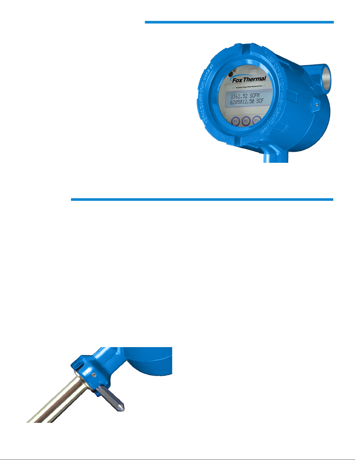
With an optional on-board 2-line x 16-character backlit
display, operators can view ow rate, total, elapsed time,
process gas temperature, and alarms. The display is also
used in conjunction with the Conguration Panel to access
ow meter settings, such as 4-20mA and pulse output
scaling, pipe diameter, zero ow cutoff, ow ltering
(damping), display options, and high or low alarm limits.
The Model FT1 is available in insertion and inline styles.
The insertion style FT1 has a robust stainless steel
probe and is easily installed by drilling a hole in the
pipe and welding on a 1” NPT coupling. A Fox Thermal-
supplied compression tting secures the probe in place.
It is supplied with 316 stainless steel wetted materials
standard. Inline styles of the FT1 are available in both
stainless steel and carbon steel with NPT and 150lb ange
options. See Specication section for details on sizing. A
USB port to connect to a computer or laptop is standard;
interface options include HART, Modbus RTU (RS485) and
BACnet MS/TP (RS485).
Fox Thermal has certied cleaning and bagging
procedures for ow meters to be used in oxygen
applications.
Advanced Features
Suitable for harsh and hazardous environments, the
instrument features:
• Robust DDC-Sensor™ Design
• Gas-SelectX® with a selection of pure gases or a
gas mix up to five gases
• CAL-V™ Calibration Validation
• Rotatable probe: allows ±180 degree swivel
• FM/FMc, ATEX, IECEx approvals. CE mark.
• 10-30VDC power input, standard
• NIST-traceable calibration
• Free FT1 View™ Software
• High and low alarm limits
• Wetted materials are all welded, 316 stainless steel
The DDC-Sensor™ allows the user to swivel the probe ±180°
into four positions.
Perfect for commercial and industrial applications, the
Model FT1 is a superior flow measurement instrument
with excellent accuracy!
Page 3

ADVANCED FEATURES
CAL-V™
For customers that need a quick and easy way to verify the
calibration of the meter in the field, the Model FT1 offers
the CAL-V™ feature. This feature can be initiated through
the meter’s optional display configuration panel or the FT1
View™ Software. The test takes fewer than 5 minutes to
run and produces a pass/fail result at the conclusion of the
test. A fail result may indicate either a dirty sensor or the
need to recalibrate.
If the CAL-V™ test is performed using the FT1 View™
software, a Calibration Validation Certificate can be
produced at the conclusion of the test. The certificate
will show the date and time of the test along with meter
data such as firmware version and meter serial number.
This in situ calibration validation helps operators comply
with environmental mandates and eliminates the cost and
inconvenience of annual factory calibration.
FT1 View™ Software
Fox Thermal has developed advanced software - FT1
View™ - a free PC-compatible application available for
download from the Fox Thermal website. Connect your
laptop, PC, or control station to the meter using the USB
port interface to access the meter’s data and configure the
meter’s settings.
FT1 View™ allows:
• Quick access to all configuration parameters with
pop-up windows and pull down menus
• Selection of measurement units, flow and
temperature ranges, alarm settings and more
• Print or save a CAL-V™ Calibration Validation
Certificate
• Set alarms; display alarm codes
• Storage of meter configurations to a file that can be
archived
• Simulation mode used to align 4-20mA output with
the input to customer’s PLC/DCS
• Raw data to be viewed in order to diagnose or
troubleshoot your meter
• Data logging to an Excel® spreadsheet
Approvals
CE Mark: Approved
EMC Directive: 2014/30/EU
Electrical Equipment for Measurement, Control, and Lab
Use: EN61326-1:2013
EU Directive: 2014/68/EU
Weld Testing: EN ISO 15614-1 and EN ISO 9606-1, ASME
B31.3
FM (FM16US0005X) & FMc (FM16CA0005X): Approved
Class I, Division 1, Groups B, C, D;
Class II, Division 1, Groups E, F, G;
Class III, Division 1; T4, Ta = -40˚ to 70˚C;
Class I, Zone 1, AEx/Ex db IIB + H2 T4; Gb Ta = -40˚C to
70˚C;
Type 4X, IP66/67
ATEX (FM16ATEX0013X): Approved
II 2 G Ex db IIB + H2 T4; Gb Ta = -40˚C to 70˚C; IP66/67
II 2 D Ex tb IIIC T135˚C; Db Ta = -40˚C to 70˚C; IP66/67
IECEx (IECEx FMG 16.0010X): Approved
Ex d IIB + H2 T4; Gb Ta = -40˚C to 70˚C; IP66/67
Ex tb IIIC T135˚C; Db Ta = -40˚C to 70˚C; IP66/67
APPROVALS & SPECIFICATIONS
Performance Specs
Flow Accuracy:
Air: ±1% of reading ±0.2% of full scale
Other gases: ±1.5% of reading ±0.5% of full scale
Accuracy specification applies to customer’s selected
flow range
Maximum range: 15 to 25,000 SFPM (0.07 to 120 NMPS)
Minimum range: 15 to 500 SFPM (0.07 to 2.4 NMPS)
Straight, unobstructed pipe requirement:
Insertion: 15 diameters upstream; 10 downstream.
Inline: 8 diameters upstream; 4 downstream.
Flow Repeatability: ±0.2% of full scale
Flow Response Time: 0.8 seconds (one time constant)
Temperature Accuracy: ±1° F (±0.6° C)
Calibration:
Factory Calibration to NIST traceable standards
CAL-V™: In-situ, operator-initiated calibration validation
ATEX and IECEx Standards:
EN 60079-0:2012 + A11:2013 IEC 60079-0:2011
EN 60079-1:2014 IEC 60079-1:2014
EN 60079-31:2014 IEC 60079-31:2013
EN 60529:1991 + A1:2000 IEC 60529:2001
Precision Mass Flow Measurement
An ON
I
CON Brand
Page 4

SPECIFICATIONS
Operating Specs
Gas-SelectX® Gas Selections:
Air, Argon, Butane, Carbon Dioxide, Ethane, Methane, Natural
Gas (NAESB gas composition), Nitrogen, Oxygen, Helium,
Hydrogen, Propane, 5-gas mix (any five gases in this list
equalling 100%). See the Fox Thermal website for more
information on current gases.
Gas Pressure (maximum; at 100°F):
Insertion: 740 psig (51 barg)
316 SS inline w/NPT ends: 500 psig (34 barg)
316 SS inline w/150lb flanges: 230 psig (16 barg)
CS inline w/NPT ends: 500 psig (34 barg)
CS inline w/150lb flanges: 285 psig (20 barg)
Retractor: 150 psig (10.3 barg)
Notes:
• Check with factory for higher pressure options.
• With Teflon Ferrule option (P/N 106415), maximum gas
pressure is 60 psig (4.1 barg).
• Pressure ratings for temperatures up to 100°F (38°C).
Temperature:
DDC-Sensor™: -40 to 250°F (-40 to 121°C)
Enclosure: -40 to 158°F (-40 to 70°C)**
**NOTE! Display dims below -4˚F (-20˚C); function returns once
temperature rises again.
Flow Velocity Range: 15 to 25,000 SFPM at 70°F (0.07 to 120
NMPS at 0°C)
Turndown: up to 1000:1; 100:1 typical
Flow Ranges - Insertion Meters
Pipe Diameter SCFM MSCFD NM3/H
1.5" (40mm) 0 - 354 0 - 510 0 - 558
2" (50mm) 0 - 583 0 - 840 0 - 920
2.5” (63mm) 0 - 830 0 - 1,310 0 - 1,200
3" (80mm) 0 - 1,280 0 - 1,840 0 - 2,020
4” (100mm) 0 - 2,210 0 - 3,180 0 - 3,480
6" (150mm) 0 - 5,010 0 - 7,210 0 - 7,910
8" (200mm) 0 - 8,680 0 - 12,500 0 - 13,700
10" (250mm) 0 - 13,600 0 - 19,600 0 - 21,450
12" (300mm) 0 - 19,400 0 - 27,900 0 - 30,600
NOTE! To determine if the FT1 will operate accurately in other pipe sizes,
divide the maximum ow rate by the pipe area. The application is acceptable
if the resulting velocity is within the velocity range above. Check Fox Thermal
website for velocity calculator.
Flow Ranges - Inline Meters
Pipe Diameter SCFM MSCFD NM3/H
0.75” 0 - 93 0 - 134 0 - 146
1” 0 - 150 0 - 216 0 - 237
1.25” 0 - 260 0 - 374 0 - 410
1.5" 0 - 354 0 - 510 0 - 558
2" 0 - 583 0 - 840 0 - 920
2.5” 0 - 830 0 - 1,310 0 - 1,200
3" 0 - 1,280 0 - 1,840 0 - 2,020
4” 0 - 2,210 0 - 3,180 0 - 3,480
6" 0 - 2,500 0 - 3,600 0 - 3,950
NOTE! Consult factory for ow ranges above those listed. Inline meters above
2,500 SCFM (3,950 NM3/H) may require third party calibration. Contact Fox
Thermal.
Relative Humidity: 90% RH maximum; non-condensing
Units of Measurement (field-selectable):
SCFM, SCFH, NM3/M, NM3/H, NM3/D, NLPS, NLPM, NLPH, MCFD,
MSCFD, SCFD, MMSCFD, MMSCFM, SM3/D, SM3/H, SM3/M, LB/S,
LB/M, LB/H, LB/D, KG/S, KG/M, KG/H, SLPM, MT/H
Input power: 12 to 28 VDC, 6 watts max.
Full input power range: 10 to 30 VDC.
A 20 Watt or greater power supply is recommended to power
the FT1
Outputs:
Channel 1: Standard isolated 4-20mA output for ow or
temperature; fault indication per NAMUR NE43; HART
communication option.
Channel 2: Option of a) pulse output or b) Serial
Communication (Modbus RTU (RS485) or BACnet MS/TP
(RS485))
Isolated pulse output: 5 to 24VDC, 20mA max., 0 to 100Hz
for ow (the pulse output can be used as an isolated solid
state output for alarms).
Serial Communication:
USB connector for connecting to a laptop or computer is
standard.
Optional isolated communication outputs: Modbus RTU
(RS485), BACnet MS/TP (RS485).
Free PC-based software tool - FT1 View™ - provides
complete conguration, remote process monitoring and
data logging functions.
4-20mA and Pulse Verication:
Simulation mode used to align 4-20mA output and pulse
output (if ordered) with the input to user’s PLC/DCS.
Physical Specs
Probe diameter: ¾”
Sensor Material: 316 stainless steel
Enclosure: NEMA 4X, aluminum, dual ¾” FNPT conduit entries.
Fox Thermal recommends the following probe lengths
(assuming no insulation around pipe):
Pipe Diameter Probe Length
1.5" (40mm) to 6" (150mm) 6-inch
8" (200mm) to 12" (300mm) 9-inch
14" (350mm) to 18" (450mm) 12-inch
Use equation below for selecting probe length of larger pipe sizes
Probe Lengths (LL*) in inches (cm) =
6.0 (15.2) 9.0 (22.9) 12.0 (30.5)
15.0 (38.1) 18.0 (45.7) 24.0 (61.0)
30.0 (76.2) 36.0 (91.4)
*See dimensional drawings on Fox Thermal website.
Dimensional
Refer to dimensional drawings on Fox Thermal website.
Equation for Selecting Probe Length
Probe length = ½ pipe ID (in inches) + 3” + thickness of
insulation (if any). Round up to the next standard probe length
available.
FT1 Rev. M
 Loading...