

Page 1
FC10 Installation Instructions for Insertion
Meters
For use with All Fox Flow Meters
Definition: The FC10 is a flow conditioner installed between two flanges upstream of the flow
meter that corrects irregular flow profiles ensuring flow meter accuracy.
Scope: The FC10 is used with flanges in schedule 40 pipe with insertion style meters.
Purpose: This procedure describes proper installation of the FC10 to ensure flow meter
accuracy.
Directions:
1. Ensure proper installation of the branch outlet for the flow meter. See Fox Document
107590 for more information.
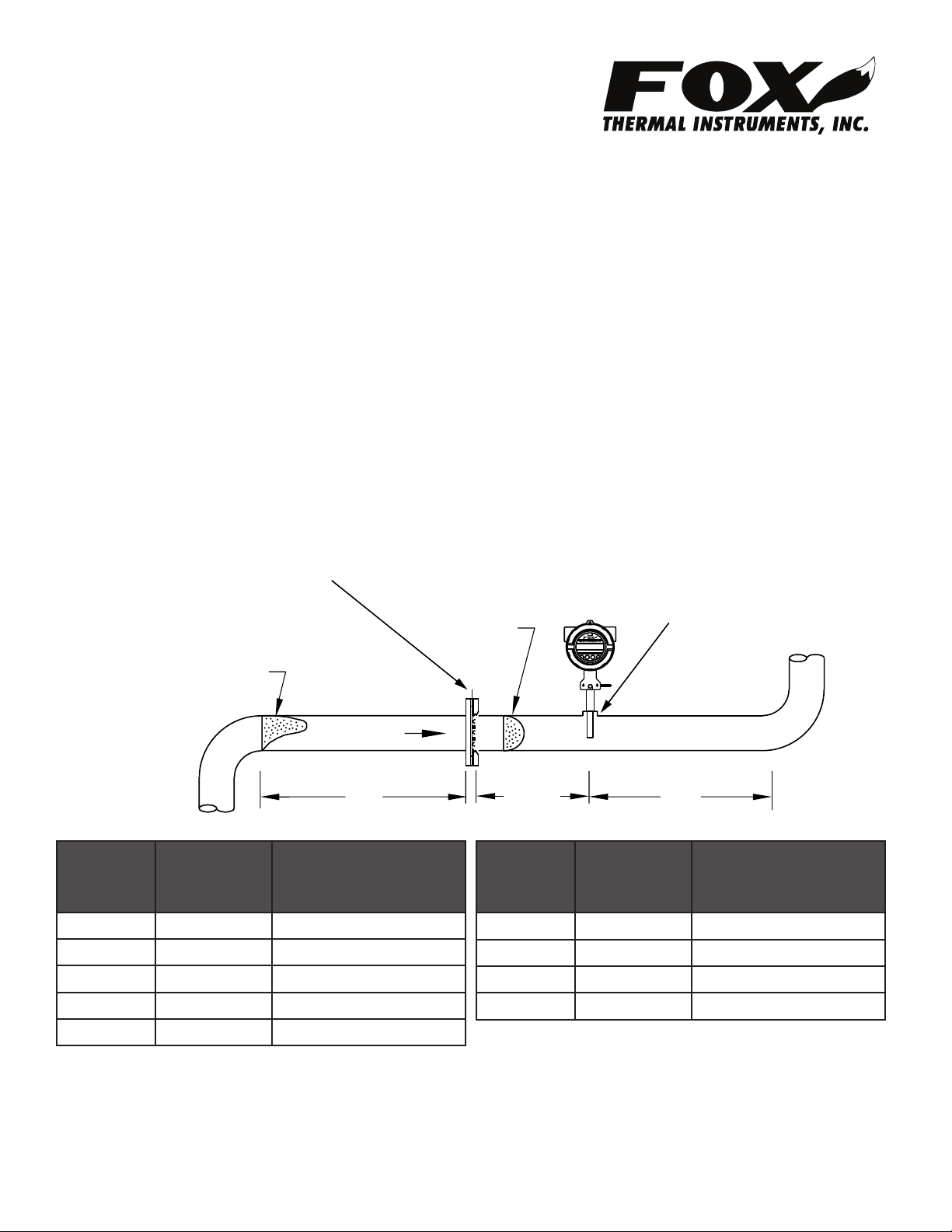
2. Determine the correct distance for dimension “X” for the appropriate schedule 40 pipe in
the table below.
Figure 1.1: FC10 Minimum Straight Run Requirements
FC10 Flow Conditioner
installed between two anges
Irregular Flow
Prole
FLOW
Schedule
40 Pipe
Size
1.5 6 (152) 8 (203)
2 6 (152) 10 (254)
2.5 9 (229) 15 (381)
3 9 (229) 15 (381)
4 9 (229) 20 (508)
“X”
Inch (mm)
5D Min. Up/Downstream
Inch (mm)
Proper
Flow
Prole
Schedule
Branch Outlet
F1
F2 F3 F4
“X”
“X”
40 Pipe
Size
5 10 (254) 25 (635)
6 12 (305) 30 (762)
8 16 (406) 40 (1016)
10 20 (508) 50 (1270)
Inch (mm)
(installed by customer)
5D5D
5D Min. Up/Downstream
Inch (mm)
Fox Thermal Instruments, Inc.
399 Reservation Road, Marina, CA 93933
www.foxthermalinstruments.com
831-384-4300
DOCUMENT NO.: 107679, REV.: B
Page 1 of 2
Page 2

3. Position the FC10 Flow Conditioner correctly between the flanges.
(customer supplied)
• The FC10 must be installed between flanges and two gaskets for optimum seal.
• Center the flow conditioner between the flanges.
• The FC10 is equipped with an orientation marker. This marker must be aligned in parallel
with the probe of the flow meter.
• The Orientation marker is also etched with “UPSTREAM” to indicate which side, or face,
of the FC10 must be pointed upstream. When installed correctly, the louvers will point
downstream.
Figure 1.2: Orientation of FC10 Flow Conditioner
Orientation marker
must be parallel to
ow meter probe
FC10 Orientation marker
with “UPSTREAM” etching
FLOW
Gaskets
(supplied by customer)
(see table previous page)
4. Tighten bolts on the flanges to complete installation of the FC10.
“X”
F1
Flow meter
F2 F3 F4
Probe
Branch Outlet
Fox Thermal Instruments, Inc.
399 Reservation Road, Marina, CA 93933
www.foxthermalinstruments.com
831-384-4300
DOCUMENT NO.: 107679, REV.: B
Page 2 of 2
 Loading...