

Page 1
Model FC10 Flow Conditioner
Precision Mass Flow Measurement
An ON
I
CON Brand
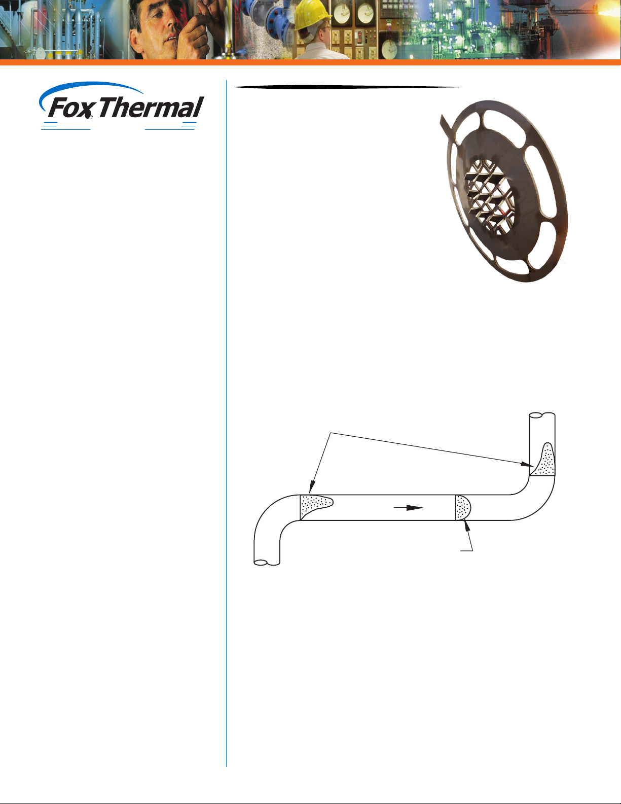
Irregular flow
profiles
Proper flow profile
FLOW
for Gas Applications
• Reduces the need for long straight pipe
runs
• Precision, laser-cut design
• 316 stainless steel material
• Creates proper gas flow profile from
irregular flow profiles
• Negligible pressure drop
• Use with insertion style flow meters
• Available in 10 sizes for schedule 40
pipes: 1.5”, 2”, 2.5”, 3”, 4”, 5”, 6”, 8”, 10”,
and 12”
• Install upstream from the flow meter
probe between 150 lb. flanges
• Easy installation in the center of the
pipe via flange matching pipe outer
diameter (OD)
FC10
Flow Conditioner
for use with Insertion
Style Flow Meters
Flow conditioners installed upstream
of ow meters reduce the need for
long, straight pipe runs.
Installation Solutions for Limited Pipe Runs
Flow meter accuracy is often dependent on achieving a uniform flow
profile near the center of the pipe. Distortion and swirl are disturbances
in flow that can be remedied either by extending the length of space
between the cause of the disturbance and the sensing element
(increasing straight pipe runs) or by adding a flow conditioner to correct
the disturbance directly.
FOX THERMAL
399 RESERVATION ROAD
MARINA, CA 93933
PHONE: 831-384-4300
FAX: 831-337-5786
sales@foxthermal.com
www.foxthermal.com
In certain circumstances, the extra space needed to accommodate flow
meters requiring more straight pipe runs upstream or downstream of
the flow meter’s flow sensor isn’t available. In these cases, it’s necessary
to find solutions to these space limitations.
Insertion thermal mass flow meters are easy to install and require
minimal straight pipe runs. In the past, the only option to reducing
straight pipe runs for very tight spaces was to order inline flow meters
with flow conditioners. In order to give customers more flexibility,
Fox Thermal has developed the FC10 flow conditioner for use with
insertion style flow meters.
Each flow meter is calibrated with the flow conditioner to ensure the
highest accuracy.
FC10 Rev. A
Page 2
SPECIFICATIONS
Flow meter
(customer supplied)
Sizing
The FC10 was designed to be used in a variety of pipe
sizes. FC10s are available in 10 sizes for schedule 40 pipes:
1.5”, 2”, 2.5”, 3”, 4”, 5”, 6”, 8”, 10”, and 12”. For pipe sizes
outside of this range, an inline ow meter is recommended.
NOTE: For pressure drop data, please visit the Fox website.
Figure 1.1: Straight Pipe Run Requirements
FC10 Flow Conditioner
installed between two flanges
Irregular Flow
Profile
FLOW
Table 1.1: Straight Pipe Run Requirements
Proper
Flow
Profile
“X”
F1
F2 F3 F4
Lateral Placement
To determine where to install the FC10 flow conditioner,
the pipe size is important. FC10s require 5D upstream.
The flow meter’s sensor should also have 5D before any
downstream disturbances. The distance between the FC10
flow conditioner and the flow meter’s sensor is dependent
on the pipe size and is listed in Table 1.1 and illustrated in
Figure 1.1 below.
TECH TIP
Branch Outlet
(installed by customer)
5D5D
Compare Upstream &
Downstream Straight
Run Requirements for
Common Flow Meter
Technologies
DP METERS
20 Upstream
10 Downstream
Schedule 40
Pipe Size
“X”
Inch (mm)
Min. Up/Downstream
Pipe Diameters Inch (mm)
1.5 6 (152) 5D 8 (203)
2 6 (152) 5D 10 (254)
2.5 9 (229) 5D 15 (381)
3 9 (229) 5D 15 (381)
4 9 (229) 5D 20 (508)
5 10 (254) 5D 25 (635)
6 12 (305) 5D 30 (762)
8 16 (406) 5D 40 (1016)
10 20 (508) 5D 50 (1270)
12 24 (610) 5D 60 (1524)
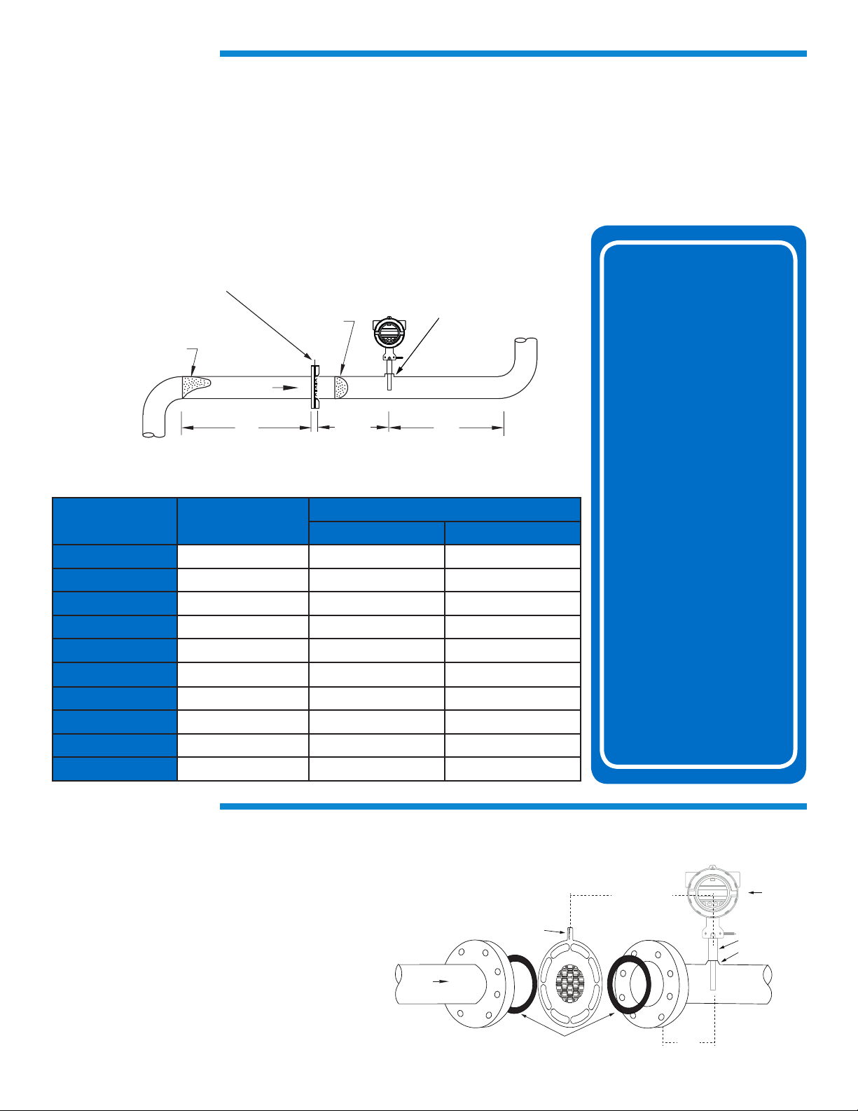
INSTALLATION
FC10 Orientation
Every FC10 has “UPSTREAM” etched into the
orientation marker at the top of the flow conditioner.
This marker should be pointing parallel to the probe
with the “UPSTREAM” etching pointing toward the
upstream portion of the pipe.
The FC10 is installed between two 150lb flanges and
gaskets (supplied by customer) should be placed on
both sides of the flow conditioner to ensure a tight
seal.
Please refer to document #107679 for further
installation instructions.
VORTEX METERS
35 Upstream
5 Downstream
TURBINE METERS
20 Upstream
5 Downstream
ULTRASONIC
METERS
10 - 20 Upstream
10 - 20 Downstream
Figure 1.2: Orientation of FC10 Flow Conditioner
Orientation marker
FLO
FC10 Orientation marker
with “UPSTREAM” etching
(supplied by customer)
Gaskets
must be parallel to
flow meter probe
(see table previous page)
F1
F2 F3 F4
Probe
Branch Outlet
“X”
 Loading...