


In order to prevent improper operation before use, please carefully read this manual.
User Manual

Table of Contents
1. Introduction............................................................................................................................................ 1
2. Symbols ................................................................................................................................................. 1
3. Safety ..................................................................................................................................................... 2
3.1 Handling ....................................................................................................................................... 2
3.2 Installation .................................................................................................................................... 2
4. Response to Emergency Situations ....................................................................................................... 2
5. Product Information ................................................................................................................................3
5.1 ECS2800 Specifications .............................................................................................................. 3
5.1.1 CS2800 Specifications .............................................................................................................. 3
5.1.2 CM2800 Specifications ............................................................................................................. 3
5.1.3 Battery System Specifications for ECS2800 ............................................................................. 4
5.2 ECS2900 Specifications .............................................................................................................. 5
5.2.1 CS2900 Specifications .............................................................................................................. 5
5.2.2 CM2900 Specifications ............................................................................................................. 5
5.2.3 Battery System Specifications for ECS2900 ............................................................................. 6
5.3 ECS4000 Specifications .............................................................................................................. 7
5.3.1 CS4000 Specifications .............................................................................................................. 7
5.3.2 CM4000 Specifications ............................................................................................................. 7
5.3.3 Battery System Specifications for ECS4000 ............................................................................. 8
5.4 ECS4100 Specifications .............................................................................................................. 9
5.4.1 CS4100 Specifications .............................................................................................................. 9
5.4.2 CM4100 Specifications ............................................................................................................. 9
5.4.3 Battery System Specifications for ECS4100 ........................................................................... 10
5.5 ECS4300H Specifications .......................................................................................................... 11
5.5.1 CS4300H Specifications ......................................................................................................... 11
5.5.2 CM4300H Specifications .........................................................................................................11
5.5.3 Battery System Specifications for ECS4300H ........................................................................ 12
5.6 ECS4800 Specifications ............................................................................................................ 13
5.6.1 CS4800 Specifications ............................................................................................................ 13
5.6.2 CM4800 Specifications ........................................................................................................... 13
5.6.3 Battery System Specifications for ECS4800 ........................................................................... 14
6. Product Features ................................................................................................................................. 15

6.1 Battery System Features ........................................................................................................... 15
7. Installation ............................................................................................................................................ 16
7.1 Items in the package .................................................................................................................. 16
7.2 Clearance ...................................................................................................................................17
7.3 Tools ...........................................................................................................................................18
7.4 Installation Steps ........................................................................................................................18
7.5 Wiring Steps ...............................................................................................................................22
7.6 System Start up ..........................................................................................................................24
8. Commissioning .....................................................................................................................................24
9. Exclusion ..............................................................................................................................................27
10. Troubleshooting and Maintenance .....................................................................................................27
10.1 Maintenance ............................................................................................................................ 27
10.2 Troubleshooting....................................................................................................................... 28
1
1. Introduction
Symbol Explanation CE mark. The inverter complies with the requirements
of the applicable CE guidelines.
This mark indicates compound UK product safety certification
requirements.
Caution, risk of electric shock.
Do not place nor install near flammable or explosive materials.
Install the product out of reach of children.
Read the instruction manual before starting installation and operation.
Do not dispose of the product with household wastes.
Disconnect the equipment before carrying out maintenance or repair.
Observe precautions for handling electrostatic discharge sensitive devices.
PE conductor terminal
Caution, risk of electric shock, energy storage timed discharge.
The document describes the installation, commissioning, maintenance and troubleshooting of the
following high voltage battery listed below.
ECS
Note: ECS = CM+CS
The battery chemistry of these products is Lithium Iron Phosphate. This manual is designed for qualified
personnel only. The tasks described in this document should be performed by authorized and qualified
technicians only.
After Installation the Installer must explain the user manual to the end user.
2. Symbols

2
3. Safety
Any work on the Batteries should be handled by authorized technicians and hence it is understood that
the technicians should familiarize themselves with the contents of this manual before any maintenance or
installation is carried out on the system.
3.1 Handling
· Do not expose battery to open flame.
· Do not place the product under direct sunlight.
· Do not place the product near flammable materials. It may lead to fire or explosion in case of
accident.
· Store in a cool and dry place with ample ventilation.
· Do not store the product near water sources.
· Store the product on a flat surface.
· Store the product out of reach of children and animals.
· Do not damage the unit by dropping, deforming, impacting, cutting or penetrating with a sharp object.
It may cause leakage of electrolyte or fire.
· Do not touch any liquid spilled from the product. There is a risk of electric shock or damage to skin.
· Always handle the battery wearing the insulated gloves.
· Do not step on the product or place any foreign objects on it. This can result in damage.
· Do not charge or discharge damaged battery.
· Do not store the battery near water sources.
3.2 Installation
· Do not connect the ECS to inverter conductors or Photo-Voltaic conductors. This will damage the
battery and may result in explosion.
· After unpacking, please check the product for damages and missing parts.
· Make sure that the inverter and battery is completely turned off before commencing installation.
· Do not interchange the positive and negative terminals of the battery.
· Ensure that there is no short circuit of the terminals or with any external device.
· Do not exceed the battery voltage rating of the inverter.
· Do not connect the battery to any incompatible inverter.
· Do not connect different battery types together.
· Please ensure that all the batteries are grounded properly.
· Do not open the battery to repair or disassemble. Only FOXESS is allowed to carry out any such
repairs.
· In case of fire, use only dry powder fire extinguisher. Liquid extinguishers should not be used.
· Install the batteries only inside approved FOXESS enclosure. Installing the battery anywhere outside
is strictly forbidden.
· Do not install the battery near water sources or places where the battery can get wet.
· Install the battery away from children or pets.
· Do not use battery in high static environment where the protection device might be damaged.
· Do not install with other batteries or cells.
· Please ensure on installation site that the deviation of voltages between new batteries and every
single present battery is less than 0.5V.
· Please ensure the new batteries mounted on-site comply to the warranty scope or have ever been
re-charged within 5 months; on top of that, please make sure the SOC of present battery system
onsite is 50%±5%.
4. Response to Emergency Situations
The batteries comprise of multiple batteries connected in series. It is designed to prevent hazards or
failures. However, FOXESS cannot guarantee their absolute safety.
Under exposure to the internal materials of the battery the following recommendations should be carried
out by the user.
· If there has been inhalation, please leave the contaminated area immediately and seek medical
attention.
· If there has been contact with eyes, rinse the eyes with running water for 15 minutes and seek
medical attention immediately.

3
· If there has been contact with the skin, wash the contacted area with soap thoroughly and seek
Specifications for CS
Model NO.
CS2800
Max. charge/discharge current (A)
48
Operating temperature (°C)
-10 ~55
Storage temperature (°C)
-10 ~ 35
Humidity
5 ~95%
Normal voltage (V)
57.6
Normal capacity (Ah)
48
Normal energy (kWh)
2.76
Battery voltage range [V]
52.2-66.2
Max. Continuous discharge/charge current (A)
48/48
(CC-CV) Standard charging current (A)
24
Constant current and voltage charging cut-off
current (A)
3
Peak discharge current (60s)
65
Dimensions (L*W*H) (mm)
570*380*163
Weight (Kg)
31±1
Communication interfaces
CAN
Specifications for CM
Model NO.
CM2800
Max. charge/discharge current (A)
48
Operating temperature (°C)
-10 ~55
Storage temperature (°C)
-10 ~ 35
Humidity
5 ~95%
Normal voltage (V)
57.6
Normal capacity (Ah)
48
Normal energy (kWh)
2.76
Battery voltage range [V]
52.2-66.2
Max. Continuous discharge/charge current (A)
48/48
(CC-CV) Standard charging current (A)
24
Constant current and voltage charging cut-off
current (A)
3
Peak discharge current (60s)
65
Dimensions (L*W*H) (mm)
570*380*178
Weight (Kg)
35±1
Communication interfaces
CAN
medical attention immediately.
· If there has been ingestion, induce vomiting and seek medical attention.
Fire Situation
In situations where the battery is on fire, if it is safe to do so, disconnect the battery pack by turn off the
circuit breaker to shut off the power to the system. Use FM-200 or Co2 fire extinguisher for the battery
and an ABC fire extinguisher for the other parts of the system.
Under any fire situation, please evacuate the people from the building immediately before trying to
extinguish it.
Water Situation
The battery modules are not water resistant. Hence care should be taken not to get it wet. If you find the
battery completely or partially submerged in water do not try to open. Contact an authorized personnel or
Fox for further instructions.
5. Product Information
1. CS is the battery module, and CM includes system controller and battery module;
2. CM contains the controller of the entire system, so each system must have one CM;
3. Our system consists of at least 1 CM+1 CS and up to 1 CM+6 CS.
4. Only ECS4000 can be used in the US market and the max battery system consists of 1CM+4CS.
5.1 ECS2800 Specifications
5.1.1 CS2800 Specifications
5.1.2 CM2800 Specifications
4
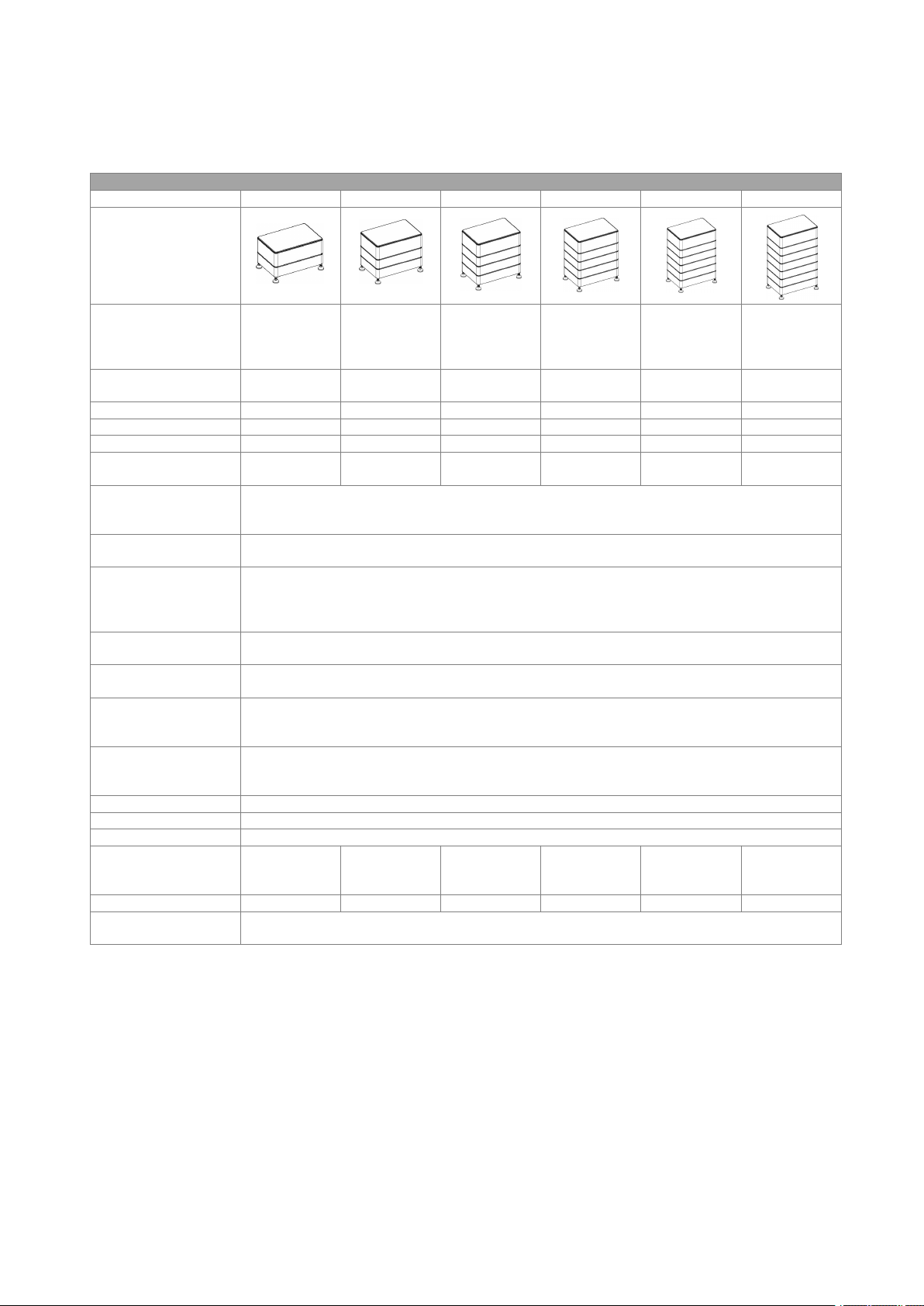
5.1.3 Battery System Specifications for ECS2800
Specifications for ECS2800
Model No.
ECS2800-H2
ECS2800-H3
ECS2800-H4
ECS2800-H5
ECS2800-H6
ECS2800-H7
Technical Properties
Battery designation*
IFpP/21/115/
103/[(2P18S)
2S]M/-10+50
/90
IFpP/21/115/
103/[(2P18S)
3S]M/-10+50
/90
IFpP/21/115/
103/[(2P18S)
4S]M/-10+50
/90
IFpP/21/115/
103/[(2P18S)
5S]M/-10+50
/90
IFpP/21/115/
103/[(2P18S)
6S]M/-10+50
/90
IFpP/21/115/
103/[(2P18S)
7S]M/-10+50
/90
The number of
batteries
1CM+1CS
1CM+2CS
1CM+3CS
1CM+4CS
1CM+5CS
1CM+6CS
Normal voltage (V)
115.2
172.8
230.4
288
345.6
403.2
Normal capacity (Ah)
4848484848
48
Normal energy (kWh)
5.53
8.29
11.06
13.82
16.59
19.35
Battery voltage
range(V)
104.4-132.4
156.6-198.7
208.8-264.9
261-331.2
313.2-397.4
365.4-463.6
Max.
charge/discharge
current (A)
48/48
(CC-CV) Standard
charging current (A)
24
Constant current and
constant voltage
charging cut-off
current (A)
3
Peak discharge
Current (60s) (A)
65
Storage
temperature (°C)
-10°C ~35°C
Operating
Temperature range
(°C)
Charge: 0°C ~55°C
Discharge: -10°C ~55°C
Discharge capacity
(Ah)
-20±2°C @1C @75%
25±2°C @0.5C @100%
55±2°C @0.5C @100%
Cycle life
≥6000 @25°C @ 70%SOH
Ingress protection
IP65
Protective class
Class 1
Demensions
(L x W x H) (mm)
570*380*366
570*380*494
570*380*622
570*380*750
570*380*878
570*380*100
6
Weight (kg)
67.5
98.5
129.5
160.5
191.5
222.5
Communication
interfaces
CAN

5
5.2 ECS2900 Specifications
Specifications for CS
Model NO.
CS2900
Max. charge/discharge current (A)
50
Operating temperature (°C)
-10 ~ 55
Storage temperature (°C)
-20 ~ 55
Humidity
5 ~95%
Normal voltage (V)
57.6
Normal capacity (Ah)
50
Normal energy (kWh)
2.88
Battery voltage range [V]
48.6-65.7
Max. Continuous discharge/charge current (A)
50/50
(CC-CV) Standard charging current (A)
25
Constant current and voltage charging cut-off
current (A)
2.5
Peak discharge current (60s)
65
Dimensions (L*W*H) (mm)
570*380*155
Weight (Kg)
31±1
Communication interfaces
CAN
Specifications for CM
Model NO.
CM2900
Max. charge/discharge current (A)
50
Operating temperature (°C)
-10 ~ 55
Storage temperature (°C)
-20 ~ 55
Humidity
5 ~95%
Normal voltage (V)
57.6
Normal capacity (Ah)
50
Normal energy (kWh)
2.88
Battery voltage range [V]
48.6-65.7
Max. Continuous discharge/charge current (A)
50/50
(CC-CV) Standard charging current (A)
25
Constant current and voltage charging cut-off
current (A)
2.5
Peak discharge current (60s)
65
Dimensions (L*W*H) (mm)
570*380*170
Weight (Kg)
35±1
Communication interfaces
CAN
5.2.1 CS2900 Specifications
5.2.2 CM2900 Specifications
6
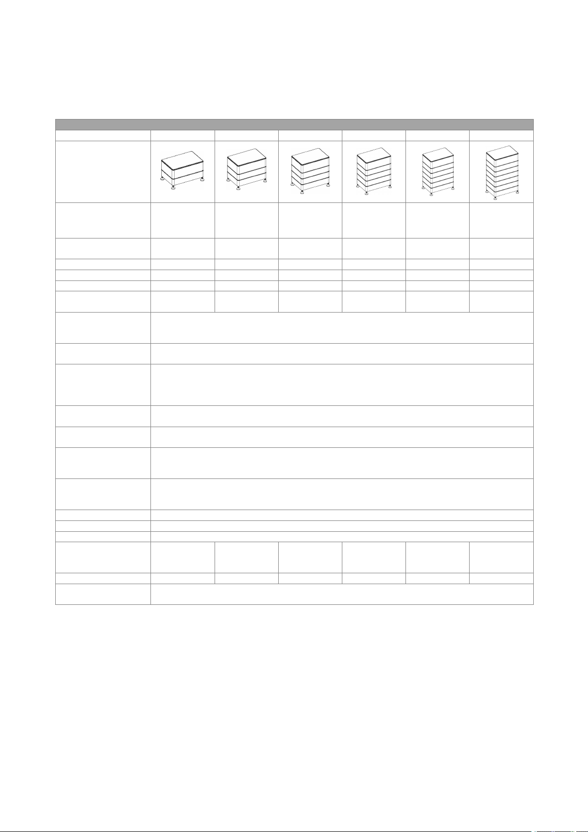
5.2.3 Battery System Specifications for ECS2900
Specifications for ECS2900
Model No.
ECS2900-H2
ECS2900-H3
ECS2900-H4
ECS2900-H5
ECS2900-H6
ECS2900-H7
Technical Properties
Battery designation*
IFpP42/151/
108/[(18S)2S
]E/-10+50/90
IFpP42/151/
108/[(18S)3S
]E/-10+50/90
IFpP42/151/
108/[(18S)4S
]E/-10+50/90
IFpP42/151/
108/[(18S)5S
]E/-10+50/90
IFpP42/151/
108/[(18S)6S
]E/-10+50/90
IFpP42/151/
108/[(18S)7S
]E/-10+50/90
The number of
batteries
1CM+1CS
1CM+2CS
1CM+3CS
1CM+4CS
1CM+5CS
1CM+6CS
Normal voltage (V)
115.2
172.8
230.4
288
345.6
403.2
Normal capacity (Ah)
5050505050
50
Normal energy (kWh)
5.76
8.64
11.52
14.4
17.28
20.16
Battery voltage
range(V)
97.2-131.4
145.8-197.1
194.4-262.8
243-328.5
291.6-394.2
340.2-459.9
Max.
charge/discharge
current (A)
50/50
(CC-CV) Standard
charging current (A)
25
Constant current and
constant voltage
charging cut-off
current (A)
2.5
Peak discharge
Current (60s) (A)
65
Storage
temperature (°C)
-20°C ~55°C
Operating
Temperature range
(°C)
Charge: 0°C ~55°C
Discharge: -10°C ~55°C
Discharge capacity
(Ah)
-20±2°C @1C @70%
25±2°C @1C @100%
55±2°C @1C @95%
Cycle life
≥6000 @25°C @ 70%SOH
Ingress protection
IP65
Protective class
Class 1
Demensions
(L x W x H) (mm)
570*380*350
570*380*470
570*380*590
570*380*710
570*380*830
570*380*950
Weight (kg)
67.5
98.5
129.5
160.5
191.5
222.5
Communication
interfaces
CAN

7
5.3 ECS4000 Specifications
Specifications for CS
Model NO.
CS4000
Max. charge/discharge current (A)
50
Operating temperature (°C)
-10 ~ 55
Storage temperature (°C)
-20 ~ 55
Humidity
5 ~95%
Normal voltage (V)
57.6
Normal capacity (Ah)
69
Normal energy (kWh)
3.97
Battery voltage range [V]
48.6-65.7
Max. Continuous discharge/charge current (A)
50/50
(CC-CV) Standard charging current (A)
35
Constant current and voltage charging cut-off
current (A)
3.5
Peak discharge current (60s)
65
Dimensions (L*W*H) (mm)
570*380*155
Weight (Kg)
35±1
Communication interfaces
CAN
Specifications for CM
Model NO.
CM4000
Max. charge/discharge current (A)
50
Operating temperature (°C)
-10 ~ 55
Storage temperature (°C)
-20 ~ 55
Humidity
5 ~95%
Normal voltage (V)
57.6
Normal capacity (Ah)
69
Normal energy (kWh)
3.97
Battery voltage range [V]
48.6-65.7
Max. Continuous discharge/charge current (A)
50/50
(CC-CV) Standard charging current (A)
35
Constant current and voltage charging cut-off
current (A)
3.5
Peak discharge current (60s)
65
Dimensions (L*W*H) (mm)
570*380*170
Weight (Kg)
39±1
Communication interfaces
CAN
5.3.1 CS4000 Specifications
5.3.2 CM4000 Specifications

8
5.3.3 Battery System Specifications for ECS4000
Specifications for ECS4000
Model No.
ECS4000-H2
ECS4000-H3
ECS4000-H4
ECS4000-H5
ECS4000-H6
ECS4000-H7
Technical Properties
Battery designation*
IFpP42/151/1
08/[(18S)2S]
E/-10+50/90
IFpP42/151/1
08/[(18S)3S]
E/-10+50/90
IFpP42/151/1
08/[(18S)4S]
E/-10+50/90
IFpP42/151/1
08/[(18S)5S]
E/-10+50/90
IFpP42/151/1
08/[(18S)6S]
E/-10+50/90
IFpP42/151/1
08/[(18S)7S]
E/-10+50/90
The number of
batteries
1CM+1CS
1CM+2CS
1CM+3CS
1CM+4CS
1CM+5CS
1CM+6CS
Normal voltage (V)
115.2
172.8
230.4
288
345.6
403.2
Normal capacity (Ah)
6969696969
69
Normal energy (kWh)
7.95
11.92
15.90
19.87
23.85
27.82
Battery voltage
range(V)
97.2-131.4
145.8-197.1
194.4-262.8
243-328.5
291.6-394.2
340.2-459.9
Max. charge/discharge
current (A)
50/50
(CC-CV) Standard
charging current (A)
35
Constant current and
constant voltage
charging cut-off current
(A)
3.5
Peak discharge
Current (60s) (A)
65
Storage
temperature (°C)
-20°C ~55°C
Operating
Temperature range
(°C)
Charge: 0°C ~55°C
Discharge: -10°C ~55°C
Discharge capacity
(Ah)
-20±2°C @1C @88%
25±2°C @1C @100%
55±2°C @1C @100%
Cycle life
≥6000 @25°C @ 70%SOH
Ingress protection
IP65
Protective class
Class 1
Demensions
(L x W x H) (mm)
570*380*350
570*380*470
570*380*590
570*380*710
570*380*830
570*380*950
Weight (kg)
75.5
110.5
145.5
180.5
215.5
250.5
Communication
interfaces
CAN

9
5.4 ECS4100 Specifications
Specifications for CS
Model NO.
CS4100
Max. charge/discharge current (A)
50
Operating temperature (°C)
-10 ~ 55
Storage temperature (°C)
-20 ~ 55
Humidity
5 ~95%
Normal voltage (V)
57.6
Normal capacity (Ah)
70
Normal energy (kWh)
4.03
Battery voltage range [V]
48.6-65.7
Max. Continuous discharge/charge current (A)
50/50
(CC-CV) Standard charging current (A)
35
Constant current and voltage charging cut-off
current (A)
3.5
Peak discharge current (60s)
65
Dimensions (L*W*H) (mm)
570*380*155
Weight (Kg)
35±1
Communication interfaces
RS485
Specifications for CM
Model NO.
CM4100
Max. charge/discharge current (A)
50
Operating temperature (°C)
-10 ~ 55
Storage temperature (°C)
-20 ~ 55
Humidity
5 ~95%
Normal voltage (V)
57.6
Normal capacity (Ah)
70
Normal energy (kWh)
4.03
Battery voltage range [V]
48.6-65.7
Max. Continuous discharge/charge current (A)
50/50
(CC-CV) Standard charging current (A)
35
Constant current and voltage charging cut-off
current (A)
3.5
Peak discharge current (60s)
65
Dimensions (L*W*H) (mm)
570*380*170
Weight (Kg)
39±1
Communication interfaces
CAN/RS485
5.4.1 CS4100 Specifications
5.4.2 CM4100 Specifications

10
5.4.3 Battery System Specifications for ECS4100
Specifications for ECS4100
Model No.
ECS4100-H2
ECS4100-H3
ECS4100-H4
ECS4100-H5
ECS4100-H6
ECS4100-H7
Technical Properties
Battery designation*
IFpP42/151/1
08/[(18S)2S]
E/-10+50/90
IFpP42/151/1
08/[(18S)3S]
E/-10+50/90
IFpP42/151/1
08/[(18S)4S]
E/-10+50/90
IFpP42/151/1
08/[(18S)5S]
E/-10+50/90
IFpP42/151/1
08/[(18S)6S]
E/-10+50/90
IFpP42/151/1
08/[(18S)7S]
E/-10+50/90
The number of
batteries
1CM+1CS
1CM+2CS
1CM+3CS
1CM+4CS
1CM+5CS
1CM+6CS
Normal voltage (V)
115.2
172.8
230.4
288
345.6
403.2
Normal capacity (Ah)
7070707070
70
Normal energy (kWh)
8.06
12.09
16.12
20.15
24.18
28.21
Battery voltage
range(V)
97.2-131.4
145.8-197.1
194.4-262.8
243-328.5
291.6-394.2
340.2-459.9
Max. charge/discharge
current (A)
50/50
(CC-CV) Standard
charging current (A)
35
Constant current and
constant voltage
charging cut-off current
(A)
3.5
Peak discharge
Current (60s) (A)
65
Storage
temperature (°C)
-20°C ~55°C
Operating
Temperature range
(°C)
Charge: 0°C ~55°C
Discharge: -10°C ~55°C
Discharge capacity
(Ah)
-20±2°C @1C @80%
25±2°C @1C @100%
55±2°C @1C @100%
Cycle life
≥6000 @25°C @ 70%SOH
Ingress protection
IP65
Protective class
Class 1
Demensions
(L x W x H) (mm)
570*380*350
570*380*470
570*380*590
570*380*710
570*380*830
570*380*950
Weight (kg)
75.5
110.5
145.5
180.5
215.5
250.5
Communication
interfaces
CAN

11
5.5 ECS4300H Specifications
Specifications for CS
Model NO.
CS4300H
Max. charge/discharge current (A)
50
Operating temperature (°C)
-10 ~ 55
Storage temperature (°C)
-20 ~ 55
Humidity
5 ~95%
Normal voltage (V)
57.6
Normal capacity (Ah)
72
Normal energy (kWh)
4.14
Battery voltage range [V]
48.6-65.7
Max. Continuous discharge/charge current (A)
50/50
(CC-CV) Standard charging current (A)
35
Constant current and voltage charging cut-off
current (A)
3.5
Peak discharge current (60s)
65
Dimensions (L*W*H) (mm)
570*380*163
Weight (Kg)
37±1
Communication interfaces
CAN
Specifications for CM
Model NO.
CM4300H
Max. charge/discharge current (A)
50
Operating temperature (°C)
-10 ~ 55
Storage temperature (°C)
-20 ~ 55
Humidity
5 ~95%
Normal voltage (V)
57.6
Normal capacity (Ah)
72
Normal energy (kWh)
4.14
Battery voltage range [V]
48.6-65.7
Max. Continuous discharge/charge current (A)
50/50
(CC-CV) Standard charging current (A)
35
Constant current and voltage charging cut-off
current (A)
3.5
Peak discharge current (60s)
65
Dimensions (L*W*H) (mm)
570*380*178
Weight (Kg)
40±1
Communication interfaces
CAN
5.5.1 CS4300H Specifications
5.5.2 CM4300H Specifications

12
5.5.3 Battery System Specifications for ECS4300H
Specifications for ECS4300H
Model No.
ECS4300H-
H2
ECS4300H-
H3
ECS4300H-
H4
ECS4300H-
H5
ECS4300H-
H6
ECS4300H-
H7
Technical Properties
Battery designation*
IFpP42/151/
108/[(18S)2S
]E/-10+50/90
IFpP42/151/
108/[(18S)3S
]E/-10+50/90
IFpP42/151/
108/[(18S)4S
]E/-10+50/90
IFpP42/151/
108/[(18S)5S
]E/-10+50/90
IFpP42/151/
108/[(18S)6S
]E/-10+50/90
IFpP42/151/
108/[(18S)7S
]E/-10+50/90
The number of
batteries
1CM+1CS
1CM+2CS
1CM+3CS
1CM+4CS
1CM+5CS
1CM+6CS
Normal voltage (V)
115.2
172.8
230.4
288
345.6
403.2
Normal capacity (Ah)
7272727272
72
Normal energy (kWh)
8.29
12.44
16.59
20.74
24.88
29.03
Battery voltage
range(V)
97.2-131.4
145.8-197.1
194.4-262.8
243-328.5
291.6-394.2
340.2-459.9
Max.
charge/discharge
current (A)
50/50
(CC-CV) Standard
charging current (A)
35
Constant current and
constant voltage
charging cut-off
current (A)
3.5
Peak discharge
Current (60s) (A)
65
Storage
temperature (°C)
-20°C ~55°C
Operating
Temperature range
(°C)
Charge: 0°C ~55°C
Discharge: -10°C ~55°C
Discharge capacity
(Ah)
-20±2°C @1C @88%
25±2°C @1C @100%
55±2°C @1C @100%
Cycle life
≥6000 @25°C @ 70%SOH
Ingress protection
IP65
Protective class
Class 1
Demensions
(L x W x H) (mm)
570*380*366
570*380*494
570*380*622
570*380*750
570*380*878
570*380*100
6
Weight (kg)
78.5
115.5
152.5
189.5
226.5
263.5
Communication
interfaces
CAN

13
5.6 ECS4800 Specifications
Specifications for CS
Model NO.
CS4800
Max. charge/discharge current (A)
50
Operating temperature (°C)
Charge: 0°C ~55°C
Discharge: -10°C ~55°C
Storage temperature (°C)
-10 ~ 35
Humidity
5 ~95%
Normal voltage (V)
44.8
Normal capacity (Ah)
104(1C)/106(1/3C)
Normal energy (kWh)
4.66(1C)/4.74(1/3C)
Battery voltage range [V]
40.6-51.5
Max. Continuous discharge/charge current (A)
50/50
(CC-CV) Standard charging current (A)
30
Constant current and voltage charging cut-off
current (A)
5.3
Peak discharge current (60s)
65
Dimensions (L*W*H) (mm)
570*380*172
Weight (Kg)
39±1
Communication interfaces
CAN
Specifications for CM
Model NO.
CM4800
Max. charge/discharge current (A)
50
Operating temperature (°C)
Charge: 0°C ~55°C
Discharge: -10°C ~55°C
Storage temperature (°C)
-10 ~ 35
Humidity
5 ~95%
Normal voltage (V)
44.8
Normal capacity (Ah)
104(1C)/106(1/3C)
Normal energy (kWh)
4.66(1C)/4.74(1/3C)
Battery voltage range [V]
40.6-51.5
Max. Continuous discharge/charge current (A)
50/50
(CC-CV) Standard charging current (A)
30
Constant current and voltage charging cut-off
current (A)
5.3
Peak discharge current (60s)
65
Dimensions (L*W*H) (mm)
570*380*188
Weight (Kg)
43±1
Communication interfaces
CAN
5.6.1 CS4800 Specifications
5.6.2 CM4800 Specifications

14
5.6.3 Battery System Specifications for ECS4800
Specifications for ECS4800
Model No.
ECS4800-H2
ECS4800-H3
ECS4800-H4
ECS4800-H5
ECS4800-H6
ECS4800-H7
Technical Properties
Battery designation*
IFpP/53/149/
113/[(14S)2S
]M/-10+50/90
IFpP/53/149/
113/[(14S)3S
]M/-10+50/90
IFpP/53/149/
113/[(14S)4S
]M/-10+50/90
IFpP/53/149/
113/[(14S)5S
]M/-10+50/90
IFpP/53/149/
113/[(14S)6S
]M/-10+50/90
IFpP/53/149/
113/[(14S)7S
]M/-10+50/90
The number of
batteries
1CM+1CS
1CM+2CS
1CM+3CS
1CM+4CS
1CM+5CS
1CM+6CS
Normal voltage (V)
89.6
134.4
179.2
224
268.8
313.6
Normal capacity (Ah)
104(1C)/106(
1/3C)
104(1C)/106(
1/3C)
104(1C)/106(
1/3C)
104(1C)/106(
1/3C)
104(1C)/106(
1/3C)
104(1C)/106(
1/3C)
Normal energy (kWh)
9.32(1C)/9.4
9(1/3C)
13.98(1C)/14
.24(1/3C)
18.64(1C)/18
.99(1/3C)
23.30(1C)/23
.74(1/3C)
27.96(1C)/28
.49(1/3C)
32.61(1C)/33
.24(1/3C)
Battery voltage
range(V)
81.2-103.0
121.8-154.5
162.4-206.0
203-257.6
243.6-309.1
284.2-360.6
Max.
charge/discharge
current (A)
50/50
(CC-CV) Standard
charging current (A)
30
Constant current and
constant voltage
charging cut-off
current (A)
5.3
Peak discharge
Current (60s) (A)
65
Storage
temperature (°C)
-10°C ~35°C
Operating
Temperature range
(°C)
Charge: 0°C ~55°C
Discharge: -10°C ~55°C
Discharge capacity
(Ah)
-20±2°C @0.5C @84%
25±2°C @0.5C @100%
55±2°C @0.5C @100%
Cycle life
≥6000 @25°C @ 70%SOH
Ingress protection
IP65
Protective class
Class 1
Demensions
(L x W x H) (mm)
570*380*386
570*380*524
570*380*662
570*380*800
570*380*938
570*380*107
6
Weight (kg)
178.5
217.5
256.5
295.5
334.5
373.5
Communication
interfaces
CAN
Note:The battery designation is a series of numbers that represent the battery's positive and
negative electrode types, structure and size, charge and discharge rate, and operating
temperature range.

15
6. Product Features
6.1 Battery System Features
The batteries have been fitted with multiple protection systems to ensure the safe operation of the system.
Some of the protection system includes:
· Inverter interface protection: Over voltage, Over current, External Short Circuit, Reverse Polarity,
Ground Fault, Over Temp, In rush current
· Battery Protection: Internal Short Circuit, Over voltage, over current, over temp, Under voltage
The battery system contains the following Interface to allow it to connect and operate efficiently.
CS Features:
- interface:
CM Features:
- interface
DC switch
Power switch, battery charge and discharge circuit switch.
DC OUT +
Connect bat + of inverter.
DC OUT -
Connect bat - of inverter.
POWER switches
System power on switch, press this switch, the system starts to work.

16
B-Start switches
No.
Items
A
Mounting screw pack
B
Installation guide
A B
E F G
A B C D
Quick
Installation
Guide
H I J
Quick
Installation
Guide
K
After power on, press this button for 5s.
BMS Status LED and SOC LED
LED display specific alarm information and battery system power.
Operating status LED
This LED is used to indicate if the battery is operating effectively. A green light on this LED means the
battery is ON and operating normally. If the battery is operating failure, a red light on this LED means the
battery is operating abnormally.
7. Installation
7.1 Items in the package
Please check if following items are including with the package:
For CS
For CM

17
For CM4000(US only)
No.
Items
No.
Items
A
Mounting screw pack
H
Installation guide
B
Fixing bracket
I
Expansion tube*2 & Expansion screw*2
C
Footstand
J
Waterproof cover
D
Communication cable (BMS-Inverter)
K
RJ45
E
Grounding cable
L
Junction box
F
DC positive output cable
M
PLUG*2
G
DC negative output cable
L M
7.2 Clearance
Make sure to leave a space of at least 300 mm. A clearance of at least 300 mm must be Ieft around the
battery pack for proper cooling.

18
Note: Make sure that the battery pack is always exposed to the ambient air. The battery pack is cooled by
natural convection. If the battery pack is entirely or partially covered or shielded, it may cause the battery
pack to stop operating.
7.3 Tools
The following tools will be required to install CM and CS.
Screw Driver Crimping Modular Safety Shoes Multimeter
Safety Gloves Safety Goggles Plier Ribbon
Electric Drill Track Level Bar Tape Marker
7.4 Installation Steps
Step 1: Install a CS with four footstand (Item C) and place it on the ground and adjust it to the level. After
installing the footstand, use a track level bar to confirm the level. Insert the waterproof cover(Item
J) into the bottom of the battery and lock it in place with the clip.

19
Step 2: Place the battery 20mm against the wall.
model.
Note: Please make sure the Operating Status LED is on your left handside when you facing the battery
Step 3: Stack the batteries one by one.
Step 4: Place the two fixing brackets (Item B) close to the wall and install them on both sides of the
battery.

20
Step 5: Mark the wall through the bracket hole.
Step 6: Punch after removing the CM. Drill holes with electric drill, make sure the holes are at least 50mm
deep, and then tighten the expansion tubes (Item I).
Step 7: After stacking CM again, fix the battery on the wall.

21
Step 8: Fix the mounting screw packs (Item A) on both sides of the battery, the installation is over.
Note: Please make sure each system including 1 CM and 1 CS. CS less than 6(1~6) pieces:
For CM4000(US only):
Note: Please make sure each system including 1 CM and 1 CS. CS less than 4(1~4) pieces:

22
Please refer to the video for the installation of the junction box and the cable gland.
For CM4000(US only):
7.5 Wiring Steps
A: Connect the inverter to make sure the wiring position is correct, as shown in the figure below.
Note: Inverter wiring refer to the inverter user manual.
For outdoor use,please use item K and proceed as follows
Connection steps:
Step 1: Prepare a standard network cable and cable connector, then insert the network cable through the
cable connector.
Step 2: Crimp the cable with a Rj45 plug which is inside of the cable connector.

23
If the usage is indoor, please use item D
Step 3: Insert the cable connector into BMS port at the bottom of inverter and screw it tightly.
B: Connect the grounding cable to ensure that all batteries are grounded. Wiring shall be connected in the
sequence as shown in below.

24
7.6 System Start up
Green LED
Red LED
Batteries Status
On for 0.5s, Off for 0.5s
On for 0.5s, Off for 0.5s
Runing in boot
On for 0.1s, Off for 0.1s
On for 0.1s, Off for 0.1s
Upgrading
On for 1s, Off for 1s
Off
Normal Working
Off
On for 1s, Off for 1s
Alarm
· When the grid connected system is started, the inverter should be turned on first to avoid the current
pulse of the inverter increasing to the battery pack.
· All installation and operation must comply with local electrical standards.
· Check all power cables and communication cables carefully.
1.
Turn on the POWER switch
· Turn on DC switch and press the POWER switch, firstly Mater LED will light up once, and then the
BMS Status LED will light up for 0.5s,Operating Status LED will light up for 1s at the same time,it
means that the system works normally.
8. Commissioning
The operating status light on the left side of the battery pack shows its working status.
For CS

25
For CM
SOC
Status
Green LED
Red LED
LED4-1
=100%
Standby
■/●●●
●
100% > SOC >= 75%
■/●●●
●
75% > SOC >= 50%
■//●●
●
50% > SOC >= 25%
■///●
●
25% > SOC >= 0%
■////
●
=100%
Discharge
●/●●●
●
100% > SOC >= 75%
●/●●●
●
75% > SOC >= 50%
●//●●
●
50% > SOC >= 25%
●///●
●
25% > SOC >= 0%
●////
●
=100%
Charge
●■■■■
100% > SOC >= 75%
●■■■■
75% > SOC >= 50%
●/■■■
50% > SOC >= 25%
●//■■
25% > SOC >= 0%
●////
■

26
Remark:
Fault
Green LED
Red LED
LED4-1
Under voltage fault
/■///
●
Over voltage fault
/■//●
/
Over temperature fault
/■//●
●
Under temperature fault
/■/●/
/
Discharge over current
/■/●/
●
Charge over current
/■/●●
/
Discharge over power
/■/●●
●
Charge over power
/■●//
/
Pre-Charge failed
/■●//
●
Short circuit Protection
/■●/●
/
AFE communication failed
/■●/●
●
Module Addressing failed
/■●●/
/
IVU Communication failed
/■●●/
●
BMU Communication failed
/■●●●
/
PCS Communication failed
/■●●●
●
HVB FUSE fault
/●///
●
Module FUSE fault
/●//●
/
Power failed
/●//●
●
Internal total voltage sampling failed
/●/●/
/
Temperature sampling failed
/●/●/
●
Relay adhesion
/●/●●
/
Relay Not Close
/●/●●
●
Relay drive failed
/●●//
/
Single Cell "0V" fault
/●●//
●
Temperature high permanent failed
/●●/●
/
The Single voltage high permanently
failed
/●●/●
●
SOH low protection
/●●●/
/
AFE failed(UV/OV/UT/OT)
/●●●/
●
Shutdown failed
/●●●●
/
Other fault
/●●●●
●
■: LED flash display (on: 0.5s, off: 0.5s)

27
●: LED on display
Storage environment
temperature
Relative humidity of the
storage environment
Storage time
SOC
Below -20℃
/
Not allowed
/
-20~35℃
5%~70%
≤ 6 months
20%≤SOC≤60%
35~55℃
5%~70%
≤ 3 months
20%≤SOC≤60%
Above 55℃
/
Not allowed
/
NOTICE
Damage to the system due to under voltages
Charge the over-discharged system within seven days when the temperature is above 25℃.
Charge the over-discharged system within seven days when the temperature is below 25℃.
9. Exclusion
The warranty shall not cover the defects caused by normal wear and tear, inadequate maintenance,
handling, storage faulty repair, modifications to the battery or pack by a third party other than FOXESS or
FOXESS agent, failure to observe the product specification provided herein or improper use or
installation, including but not limited to the following.
· Damage during transport or storage.
· Incorrect Installation of battery into pack or maintenance.
· Use of battery pr pack in inappropriate environment.
· Improper, inadequate, or incorrect charge, discharge or production circuit other than stipulated
herein.
· Incorrect use or inappropriate use.
· Insufficient ventilation.
· Ignoring applicable safety warnings and instructions.
· Altering or attempted repairs y unauthorized personnel.
· In case of force majeure (ex: lightning, storm, flood, fire, earthquake, etc.).
· There are no warranties-implied or express-other than those stipulated herein. Fox or FOXESS shall
not be liable for any consequential or indirect damages arising or in connection with the product
specification, battery or pack.
10. Troubleshooting and Maintenance
10.1 Maintenance
A. Regularly check whether the service environment of the battery meets the requirements, and the
installation position should be far away from the heat source.
B. The battery module should be stored in an environment with a temperature range between -20℃-
+55℃, and charged regularly according to the table below with no more than 0.5 C(A C-rate is a
measure of the rate at which a battery is discharged relative to its maximum capacity.) to the SOC
of 50% after a long time of storage.
C. Regularly check whether the battery and its supporting terminals, connecting cables and indicator
lights are normal.

28
10.2 Troubleshooting
When the red / green LED on the panel is flashing or normally on, it does not mean that the CS is
abnormal, it may be just an alarm or protection. Please check the ‘LED status indicators’ in chapter 7 for
the detailed faulty definition before any trouble-shooting steps. In general, the alarm indication is normal
without manual intervention. When the alarm triggering state is removed, CS will automatically return to
normal use.
- Problem determination based on the following points
1) Whether the green light on the power switch is on;
2) Whether the buzzer in CM on;
3) Whether the battery system can be communicated with inverter;
4) Whether the battery can be output voltage or not.
- Preliminary determination steps
Battery system cannot work, when DC switch on and POWER on, the LED doesn’t light up or flash,
please consider contact the local distributor.
1) The LED display of CM and CS is normal, but it cannot charge and discharge. Observe the display
screen of inverter and there is no SOC. Please check whether the CAN communication between
CM to inverter is well connected. If the connection is good, please replace a CAN communication
cable. If the SOC is still not visible on the inverter display screen, please contact the local
distributor.
2) After the battery system is powered on, if you can see the alarm information on the LED and inverter
display screen at the same time, please contact the local distributor.

The copyright of this manual belongs to FOXESS CO., LTD. Any corporation
or individual should not plagiarize, partially or fully copy (including software, etc.), and no
reproduction or distribution of it in any form or by any means is permitted. All rights reserved.
Add: No.939, Jinhai Third Road, New Airport Industry Area, Longwan District, Wenzhou,
Zhejiang, China
Tel: 0510- 68092998
WWW.FOX-ESS.COM.
V1.1
10-500-10068-01
 Loading...