

Page 1
1
Easy Installation Guide
P/N: 91-185-U48-A0-0E
Remark:
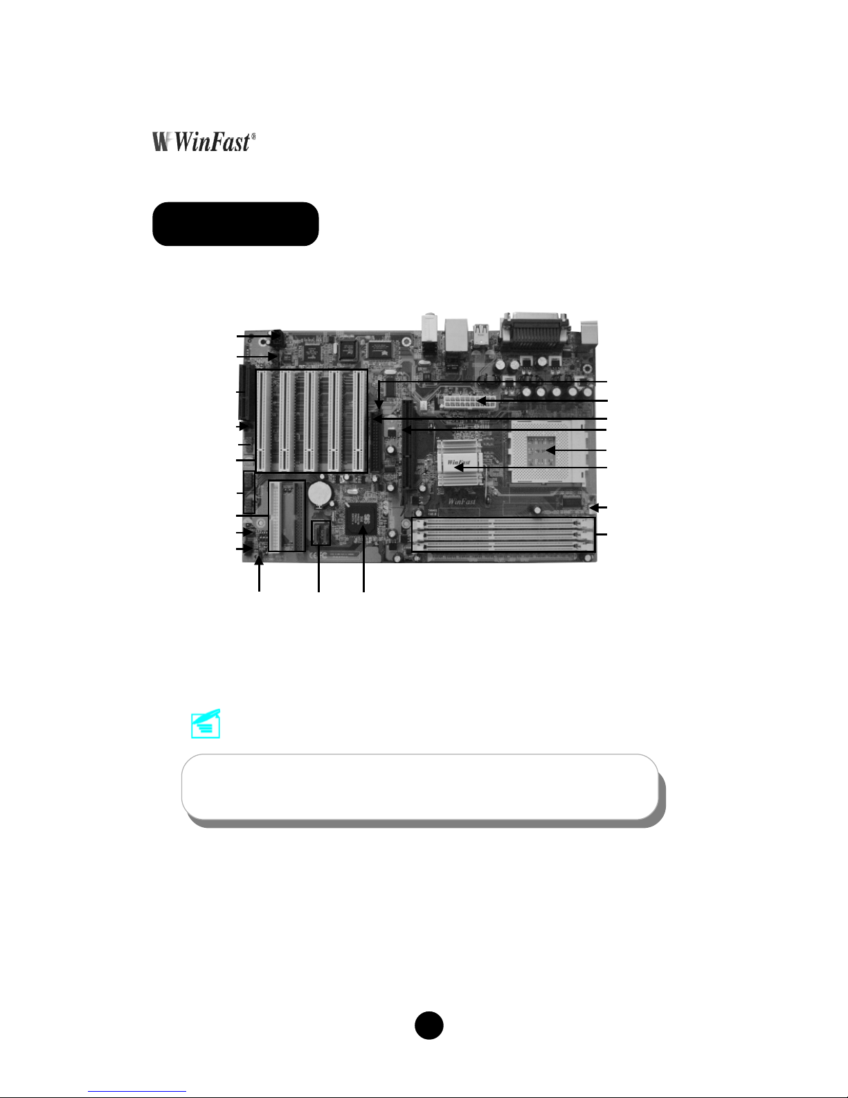
The above motherboard layout is provided for reference only;
please refer to the physical motherboard.
748K7AA Layout
SiS 964/964L
Chipset
CD_IN Connector
FDD Connector
SATA
Connector
(optional)
Front Panel
Connector
184-pin DIMM Slots
CPU FAN Connector
462-pin CPU Socket
SiS 748 Chipset
USB2.0 Connector
Front Audio
Connector
8X AGP Slot
PCI Expansion Slots
Clear CMOS Jumper
ATA 66/100/133
IDE Connectors
Speaker Connector
1394 Connector
(optional)
CNR AudioSelection
Jumper (optional)
CNR Slot (optional)
ATX Power Connector
FSB100MHz CPU
Selection Jumper
Page 2
2
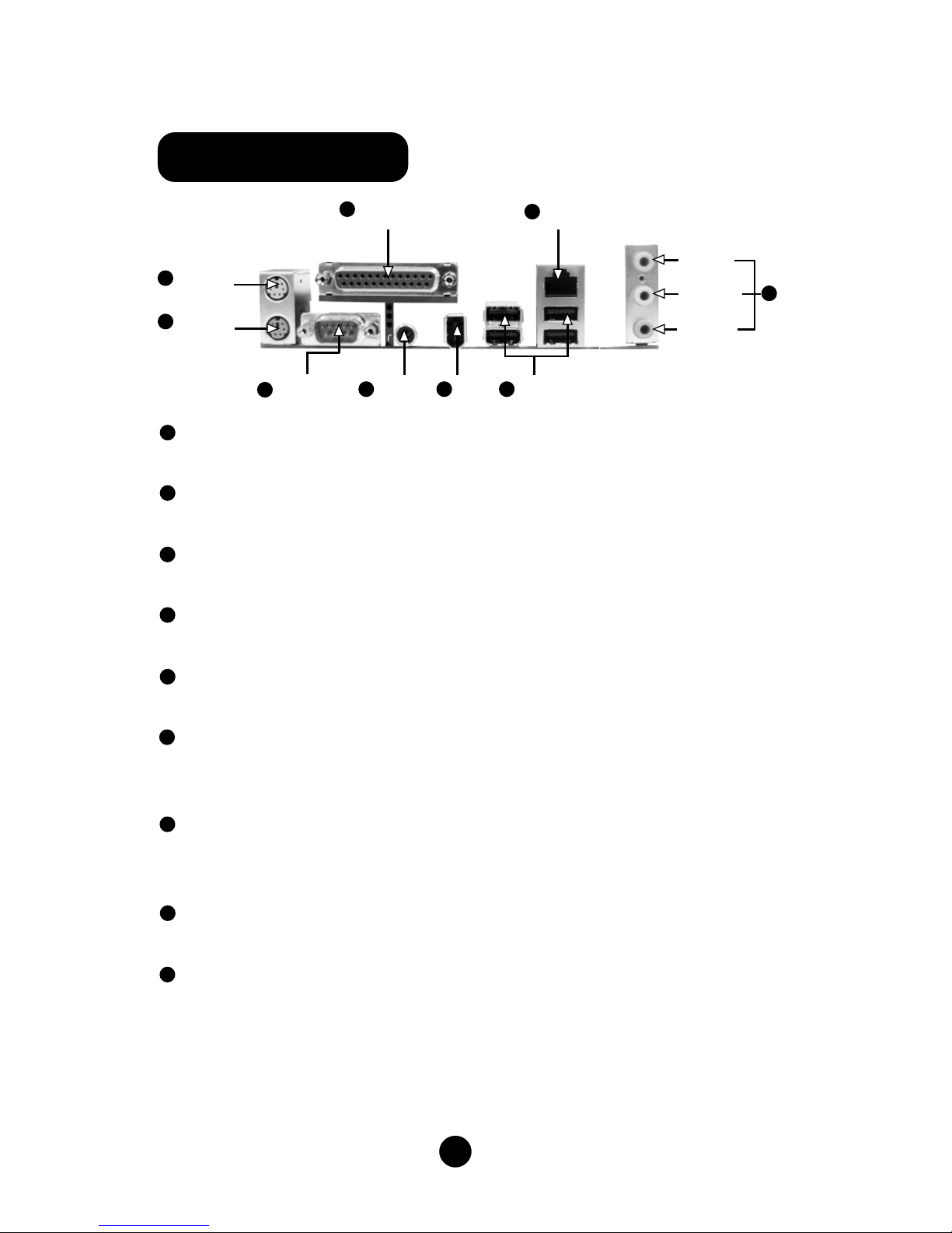
748K7AA Rear Panel
PS/2 Mouse Connector
This green 6-pin connector is for a PS/2 mouse.
PS/2 Keyboard Connector
This purple 6-pin connector is for a PS/2 keyboard.
Serial Port (COM1)
This 9-pin COM1 port is for pointing devices or other serial devices.
Parallel Port (Printer Port)
This 25-pin port connects a parallel printer, a scanner, or other devices.
S/PDIF Coaxial Out Port
This port connects to external audio output devices with coaxial cable connectors.
1394 Port (optional)
This digital interface supports electronic devices such as digital cameras,
scanners, and printers.
USB 2.0 Ports
These four Universal Serial Bus (USB) ports are available for connecting USB 2.0 /
1.1 devices.
LAN Connector
This port allows connection to a Local Area Network (LAN) through a network hub.
Line-in jack, Line-out jack, Microphone jack
Use the three audio ports to connect audio devices. The Line-in jack is for a tape
player or other audio sources. The Line-out jack is for a headphone or a speaker.
The Microphone jack is for a microphone. In 6-Channel mode, the function of the
three jacks becomes Rear Speaker Out, Front Speaker Out and Center/Subwoofer
Speaker respectively.
Serial Port
(COM1)
1394
Port
USB 2.0
Ports
PS/2 Mouse
Connector
Parallel Port
(Printer Port)
LAN Connector
1
2
7
8
PS/2 Keyboard
Connector
3
Line-in jack
Line-out jack
9
Microphone
jack
6
4
5
S/PDIF
Coaxial Out
Port
1
2
5
3
4
6
7
8
9
Page 3

3
748K7AA Motherboard (x1)
WinFast Utility CD (x1)
Easy Installation Guide (x1)
IDE Ribbon Cable (x1)
FDD Ribbon Cable (x1)
I/O Shield (x1)
S-AT A Signal Cable (x2) (optional)
S-ATA Power Cable (x1) (optional)
SiS 964 RAID Floppy Disk (x1) (optional)
CPU:
Supports AMD K7 CPU
Supports FSB at 200/266/333/400 MHz
Memory:
Supports PC3200/PC2700/PC2100
Supports 128/256/512 Mb technology up to 3 GB
Accessory Checklist
1. Support CPU & Memory
Page 4

4
You can clear CMOS to restore default system setting. To clear the CMOS, follow
the procedures described below.
1. Turn off the AC power supply and connect pin 1 and 2 together using the jumper
cap .
2. Return the jumper setting to normal (pin2 and 3 together with the jumper cap).
3. Turn the AC power supply back on.
Normal (Default)
Clear CMOS
CLS_CMOS
2. Clear CMOS Jumper: CLS_CMOS
1
1
This jumper is used to select FSB100MHz K7 CPU. The default state for J8 is
OPEN. When you want to use FSB100 MHz K7 CPU, set this jumper as CLOSE.
3. FSB100 MHz CPU Selection Jumper: J8
J8
1
Open
(Default)
1
Close for
FSB100MHz CPU
Page 5

5
This jumper is used to set enable or disable CNR audio function. The default state
for J9 is set to disable (Pin1 & Pin2 together), then you cannot use the CNR audio
and onboard audio is avaliable. If you want to use CNR audio function, set J9 to
enable (Pin2 & Pin3 together).
4. CNR Audio Selection Jumper (optional): J9
1
1
Enable
CNR Audio
Disable
CNR Audio
(Default)
J9
Attach the power LED, IDE LED, reset switch and power switch connectors to the
corresponding pins.
5. Front Panel Connector: FP
FP
+
-
1 +
-
NC
IDE_LED
RESET
Page 6

6
Plug the CPU cooling fan cable into the 3-pin CPU_FAN power supply on the mainboard.
Connect the case cooling fan connector to FAN1.
6. CPU_FAN & FAN1
The 1394 expansion cable can be connected to either the front (provided that
the front panel of your chassis is equipped with the appropriate interface) or
rear panel of the chassis.
7. 1394 Header (optional): F_1394
TPA+
F_1394
10
9
GND
TPB+
+12V
Empty
2
1
GND
TPB+12V
TPA-
GND
CPU_FAN
FAN1
Page 7

7
The USB header is available for additional USB port if the USB ports on the rear
panel are inadequate. Compared to traditional USB 1.1 with the speed of 12Mbps,
USB 2.0 has a fancy speed up to 480Mbps, which allows faster Internet connection,
interactive gaming, and simutaneous running of high-speed peripherals.
8. USB Header: F_USB1, F_USB2
F_USB1
2
F_USB2
2
CD_IN is Sony standard CD audio connector. It can be connected to a CD-ROM
drive through a CD audio cable.
9. CD_IN Connector: CD_IN
Page 8

8
The audio interface provides two kinds of audio output choices: the Front Audio,
the Rear Audio. Their priority is sequenced from high to low (Front Audio to Rear
Audio). If headphones are plugged into the front panel of the chassis (using the
Front Audio), then the Line-out (Rear Audio) on the rear panel will not work. If you
do not want to use the Front Audio, pin 5 and 6, pin 9 and 10 must be SHORT, and
then the signal will be sent to the rear audio port.
10. Front Audio Connector: F_AUDIO
The speaker connector is used to connect speaker of the chassis.
11. Speaker Connector: SPEAKER
1
SPEAKER
Page 9

9
The motherboard is equipped with the Realtek ALC655 chip, which provides support for 6-Channel audio output, including 2 front, 2 rear, 1 center and 1 subwoofer
channel. ALC655 allows the board to attach 4 or 6 speakers for a better surround
sound effect. To apply this function, you have to install the audio driver in utility CD
as well as an audio application supporting 5.1 Channel. Picture bellow represents the standard location of all speakers in 5.1 Channel sound track.
12. 5.1 Channel Audio Effects
Front
Left
Front
Right
Rear Left
Rear Right
Center
Blue
Green
Red
Subwoofer
After you finish the setting of jumpers and connect correct cables, power on the
system and press <Del> during POST (Power On Self Test) to enter the BIOS Setup
Utility. Choose “Load Optimized Defaults” for recommended optimal performance.
Please make sure your system components are good enough for optimized defaults.
13. Power on and Load Optimized Defaults
Select this option
and press <Enter>.
Page 10

10
This motherboard comes with one Utility CD. To begin using the CD, simply insert
the CD disc into the CD-ROM drive. The CD will automatically bring up the main
menu screen. Click “Install Driver”, then click the relevant button to install IDE
Driver, AG P Driver, DirectX 9.0b, USB2.0 Driver, Audio Driver and LAN Driver from
this CD.
Follow the screen order to
install the motherboard
drivers.
14. WinFast Utility CD
 Loading...